
CiA
®
301
CANopen application layer and communication profile
Application layer and communication profile
Version: 4.2.0
21 February 2011
CAN in Automation (CiA) e. V.

CANopen application layer and communication profile
2 © CiA 2011 – All rights reserved
HISTORY
Date Changes
1994-11-01 Publication of version 1.0 as draft standard proposal
1995-01-01 Publication of version 1.1 as draft standard proposal
1995-09-22 Publication of version 2.0 as draft standard proposal
1996-10-30 Publication of version 3.0 as draft standard
1999-06-16 Publication of version 4.0 as draft standard
2000-06-01 Publication of version 4.0.1 as draft standard
2002-02-13 Publication of version 4.0.2 as draft standard
2006-08-15 Publication of version 4.1 as draft standard proposal
2007-12-07 Publication of version 4.2 as draft standard proposal
2011-02-21 Publication of version 4.2.0 as public specification
NOTE: This document has been converted into “docx format”.
The conversion caused minor layout differences to the predecessor document in “doc format”. The
technical content word-by-word is the very same.
General information on licensing and patents
CAN in AUTOMATION (CiA) calls attention to the possibility that some of the elements of this CiA
specification may be subject of patent rights. CiA shall not be responsible for identifying any or all such
patent rights.
Because this specification is licensed free of charge, there is no warranty for this
specification, to the extent permitted by applicable law. Except when otherwise stated in
writing the copyright holder and/or other parties provide this specification “as is” without
warranty of any kind, either expressed or implied, including, but not limited to, the implied
warranties of merchantability and fitness for a particular purpose. The entire risk as to the
correctness and completeness of the specification is with you. Should this specification prove
failures, you assume the cost of all necessary servicing, repair or correction.
Trademarks
CANopen and CiA are registered community trademarks of CAN in Automation. The use is
restricted for CiA members or owners of CANopen® vendor ID. More detailed terms for the
use are available from CiA.
© CiA 2011
All rights reserved. Unless otherwise specified, no part of this publication may be reproduced or
utilized in any form or by any means, electronic or mechanical, including photocopying and microfilm,
without permission in writing from CiA at the address below.
CAN in Automation e. V.
Kontumazgarten 3
DE - 90429 Nuremberg, Germany
Tel.: +49-911-928819-0
Fax: +49-911-928819-79
Url: www.can-cia.org
Email: headquarters@can-cia.org

CANopen application layer and communication profile
© CiA 2011 – All rights reserved 3
CONTENTS
1
Scope ............................................................................................................................................. 12
2 References .................................................................................................................................... 13
2.1 Normative references .............................................................................................................. 13
2.2 Informative references ............................................................................................................ 13
3 Abbreviations and definitions ..................................................................................................... 14
3.1 Abbreviations .......................................................................................................................... 14
3.2 Definitions ............................................................................................................................... 14
4 Modeling ........................................................................................................................................ 16
4.1 Field device model .................................................................................................................. 16
4.2 Communication reference model ............................................................................................ 17
4.2.1 General ............................................................................................................................ 17
4.2.2 CANopen application layer .............................................................................................. 17
4.2.2.1 General ........................................................................................................................ 17
4.2.2.2 Service primitives ........................................................................................................ 17
4.2.2.3 Application layer services ............................................................................................ 18
4.3 CANopen device model .......................................................................................................... 18
4.3.1 General ............................................................................................................................ 18
4.4 Communication protocol sequences ....................................................................................... 19
4.4.1 General ............................................................................................................................ 19
4.4.2 Master/slave protocol ....................................................................................................... 19
4.4.3 Client/server protocol ....................................................................................................... 20
4.4.4 Producer/consumer protocol – pull/push model .............................................................. 20
4.4.5 The object dictionary ........................................................................................................ 21
4.5 Network system model ............................................................................................................ 21
4.5.1 Device profile ................................................................................................................... 21
4.5.2 Application profile ............................................................................................................ 21
5 Physical layer ............................................................................................................................... 22
5.1 Reference to OSI model ......................................................................................................... 22
5.2 Medium dependent interface .................................................................................................. 22
5.3 Physical medium attachment .................................................................................................. 22
5.4 Physical signaling .................................................................................................................... 22
6 Data link layer ............................................................................................................................... 24
6.1 General ................................................................................................................................... 24
6.2 CAN frame type ....................................................................................................................... 24
7 Application layer .......................................................................................................................... 25
7.1 Data types and encoding rules ............................................................................................... 25
7.1.1 General description of data types and encoding rules .................................................... 25
7.1.2 Data type definitions ........................................................................................................ 25
7.1.3 Bit sequences .................................................................................................................. 26
7.1.3.1 Definition of bit sequences .......................................................................................... 26
7.1.3.2 Transfer syntax for bit sequences ............................................................................... 26
7.1.4 Basic data types............................................................................................................... 27
7.1.4.1 General ........................................................................................................................ 27
7.1.4.2 NIL ............................................................................................................................... 27

CANopen application layer and communication profile
4 © CiA 2011 – All rights reserved
7.1.4.3 Boolean ....................................................................................................................... 27
7.1.4.4 Void ............................................................................................................................. 27
7.1.4.5 Unsigned Integer ......................................................................................................... 27
7.1.4.6 Signed Integer ............................................................................................................. 28
7.1.4.7 Floating-Point Numbers ............................................................................................... 28
7.1.5 Compound data types ...................................................................................................... 29
7.1.6 Extended data types ........................................................................................................ 30
7.1.6.1 General ........................................................................................................................ 30
7.1.6.2 Octet String .................................................................................................................. 30
7.1.6.3 Visible String ................................................................................................................ 30
7.1.6.4 Unicode String ............................................................................................................. 30
7.1.6.5 Time of Day ................................................................................................................. 30
7.1.6.6 Time Difference ........................................................................................................... 30
7.1.6.7 Domain ........................................................................................................................ 31
7.2 Communication objects ........................................................................................................... 31
7.2.1 General ............................................................................................................................ 31
7.2.2 Process data object (PDO) .............................................................................................. 31
7.2.2.1 General ........................................................................................................................ 31
7.2.2.2 Transmission modes ................................................................................................... 32
7.2.2.3 Triggering modes ......................................................................................................... 33
7.2.2.4 PDO services ............................................................................................................... 33
7.2.2.4.1 General ............................................................................................................... 33
7.2.2.4.2 Service PDO write .............................................................................................. 33
7.2.2.4.3 Service PDO read ............................................................................................... 34
7.2.2.5 PDO protocol ............................................................................................................... 34
7.2.2.5.1 Protocol PDO write ............................................................................................. 34
7.2.2.5.2 Protocol PDO read .............................................................................................. 35
7.2.3 Multiplex PDO (MPDO) .................................................................................................... 35
7.2.3.1 General ........................................................................................................................ 35
7.2.3.2 MPDO address modes ................................................................................................ 35
7.2.3.2.1 Destination address mode (DAM) ...................................................................... 35
7.2.3.2.2 Source address mode (SAM) ............................................................................. 35
7.2.3.3 MPDO service ............................................................................................................. 36
7.2.3.3.1 General ............................................................................................................... 36
7.2.3.3.2 Service MPDO write ........................................................................................... 36
7.2.3.4 MPDO protocol ............................................................................................................ 36
7.2.3.4.1 Protocol MPDO write .......................................................................................... 36
7.2.4 Service data object (SDO) ............................................................................................... 37
7.2.4.1 General ........................................................................................................................ 37
7.2.4.2 SDO services ............................................................................................................... 38
7.2.4.2.1 General ............................................................................................................... 38
7.2.4.2.2 Service SDO download ....................................................................................... 39
7.2.4.2.3 Service SDO download initiate ........................................................................... 39
7.2.4.2.4 Service SDO download segment ........................................................................ 40
7.2.4.2.5 Service SDO upload ........................................................................................... 41
7.2.4.2.6 Service SDO upload initiate ................................................................................ 41
7.2.4.2.7 Service SDO upload segment ............................................................................ 42

CANopen application layer and communication profile
© CiA 2011 – All rights reserved 5
7.2.4.2.8 Service SDO block download ............................................................................. 43
7.2.4.2.9 Service SDO block download initiate .................................................................. 43
7.2.4.2.10 Service SDO block download sub-block ............................................................. 44
7.2.4.2.11 Service SDO block download end ...................................................................... 44
7.2.4.2.12 Service SDO block upload .................................................................................. 45
7.2.4.2.13 Service SDO block upload initiate ...................................................................... 45
7.2.4.2.14 Service SDO block upload sub-block ................................................................. 46
7.2.4.2.15 Service SDO block upload end ........................................................................... 47
7.2.4.2.16 Service SDO abort transfer ................................................................................. 47
7.2.4.3 SDO protocols ............................................................................................................. 48
7.2.4.3.1 General ............................................................................................................... 48
7.2.4.3.2 Protocol SDO download ..................................................................................... 48
7.2.4.3.3 Protocol SDO download initiate .......................................................................... 49
7.2.4.3.4 Protocol SDO download segment ...................................................................... 50
7.2.4.3.5 Protocol SDO upload .......................................................................................... 50
7.2.4.3.6 Protocol SDO upload initiate............................................................................... 51
7.2.4.3.7 Protocol SDO upload segment ........................................................................... 52
7.2.4.3.8 Protocol SDO block download ............................................................................ 53
7.2.4.3.9 Protocol SDO block download initiate ................................................................ 53
7.2.4.3.10 Protocol SDO block download sub-block ........................................................... 55
7.2.4.3.11 Protocol SDO block download end ..................................................................... 56
7.2.4.3.12 Protocol SDO block upload................................................................................. 57
7.2.4.3.13 Protocol SDO block upload initiate ..................................................................... 58
7.2.4.3.14 Protocol SDO block upload sub-block ................................................................ 59
7.2.4.3.15 Protocol SDO block upload end ......................................................................... 59
7.2.4.3.16 CRC calculation algorithm to verify SDO block transfer ..................................... 60
7.2.4.3.17 Protocol SDO abort transfer ............................................................................... 61
7.2.5 Synchronization object (SYNC) ....................................................................................... 62
7.2.5.1 General ........................................................................................................................ 62
7.2.5.2 SYNC services ............................................................................................................ 62
7.2.5.2.1 General ............................................................................................................... 62
7.2.5.2.2 Service SYNC write ............................................................................................ 62
7.2.5.3 SYNC protocol ............................................................................................................. 63
7.2.5.3.1 Protocol SYNC write ........................................................................................... 63
7.2.6 Time stamp object (TIME) ............................................................................................... 63
7.2.6.1 General ........................................................................................................................ 63
7.2.6.2 TIME services .............................................................................................................. 63
7.2.6.2.1 General ............................................................................................................... 63
7.2.6.2.2 Service TIME write .............................................................................................. 63
7.2.6.3 TIME protocol .............................................................................................................. 64
7.2.6.3.1 Protocol TIME write ............................................................................................ 64
7.2.7 Emergency object (EMCY) .............................................................................................. 64
7.2.7.1 Emergency object usage ............................................................................................. 64
7.2.7.2 Emergency object services ......................................................................................... 67
7.2.7.2.1 General ............................................................................................................... 67
7.2.7.2.2 Service EMCY write ............................................................................................ 67
7.2.7.3 Emergency object protocol .......................................................................................... 67

CANopen application layer and communication profile
6 © CiA 2011 – All rights reserved
7.2.7.3.1 Protocol EMCY write ........................................................................................... 67
7.2.8 Network management ...................................................................................................... 68
7.2.8.1 General ........................................................................................................................ 68
7.2.8.2 NMT services ............................................................................................................... 68
7.2.8.2.1 Node control services ......................................................................................... 68
7.2.8.2.2 Error control services .......................................................................................... 70
7.2.8.2.3 Boot-up service ................................................................................................... 72
7.2.8.3 NMT protocols ............................................................................................................. 72
7.2.8.3.1 Node control protocols ........................................................................................ 72
7.2.8.3.2 Error Control Protocols ....................................................................................... 74
7.2.8.3.3 Protocol boot-up ................................................................................................. 77
7.3 Network initialization and system boot-up .............................................................................. 77
7.3.1 Simplified NMT startup .................................................................................................... 77
7.3.2 NMT state machine .......................................................................................................... 77
7.3.2.1 Overview ...................................................................................................................... 77
7.3.2.2 NMT states .................................................................................................................. 78
7.3.2.2.1 NMT state Initialisation ....................................................................................... 78
7.3.2.2.2 NMT state Pre-operational .................................................................................. 79
7.3.2.2.3 NMT state Operational ........................................................................................ 79
7.3.2.2.4 NMT state Stopped ............................................................................................. 79
7.3.2.2.5 NMT states and communication object relation.................................................. 80
7.3.2.3 NMT state transitions................................................................................................... 80
7.3.3 Generic pre-defined connection set ................................................................................. 80
7.3.4 Specific pre-defined connection set ................................................................................. 81
7.3.5 Restricted CAN-IDs ......................................................................................................... 81
7.4 Object dictionary ..................................................................................................................... 82
7.4.1 General structure ............................................................................................................. 82
7.4.2 Index and sub-index usage .............................................................................................. 83
7.4.3 Object code usage ........................................................................................................... 84
7.4.4 Data type usage ............................................................................................................... 84
7.4.5 Access usage................................................................................................................... 85
7.4.6 Category and entry category usage ................................................................................ 85
7.4.7 Data type entry usage ...................................................................................................... 85
7.4.7.1 General ........................................................................................................................ 85
7.4.7.2 Organization of structured object dictionary entries .................................................... 88
7.4.8 Specification of pre-defined complex data types ............................................................. 88
7.4.8.1 PDO communication parameter record specification .................................................. 88
7.4.8.2 PDO mapping parameter record specification ............................................................ 88
7.4.8.3 SDO parameter record specification ........................................................................... 89
7.4.8.4 Identity record specification ......................................................................................... 89
7.4.8.5 OS debug record specification .................................................................................... 89
7.4.8.6 OS Command record specification .............................................................................. 90
7.5 Communication profile specification ....................................................................................... 90
7.5.1 Object and entry description specification ....................................................................... 90
7.5.2 Detailed specification of communication profile specific objects ..................................... 91
7.5.2.1 Object 1000
h
: Device type ........................................................................................... 91
7.5.2.2 Object 1001
h
: Error register ......................................................................................... 92

CANopen application layer and communication profile
© CiA 2011 – All rights reserved 7
7.5.2.3 Object 1002
h
: Manufacturer status register ................................................................. 93
7.5.2.4 Object 1003
h
: Pre-defined error field ........................................................................... 93
7.5.2.5 Object 1005
h
: COB-ID SYNC message ...................................................................... 95
7.5.2.6 Object 1006
h
: Communication cycle period ................................................................ 96
7.5.2.7 Object 1007
h
: Synchronous window length ................................................................. 97
7.5.2.8 Object 1008
h
: Manufacturer device name ................................................................... 97
7.5.2.9 Object 1009
h
: Manufacturer hardware version ............................................................ 98
7.5.2.10 Object 100A
h
: Manufacturer software version ........................................................ 98
7.5.2.11 Object 100C
h
: Guard time ....................................................................................... 98
7.5.2.12 Object 100D
h
: Life time factor ................................................................................. 99
7.5.2.13 Object 1010
h
: Store parameters ............................................................................ 100
7.5.2.14 Object 1011
h
: Restore default parameters ............................................................ 102
7.5.2.15 Object 1012
h
: COB-ID time stamp object ............................................................. 105
7.5.2.16 Object 1013
h
: High resolution time stamp ............................................................. 106
7.5.2.17 Object 1014
h
: COB-ID EMCY ............................................................................... 106
7.5.2.18 Object 1015
h
: Inhibit time EMCY........................................................................... 107
7.5.2.19 Object 1016
h
: Consumer heartbeat time ............................................................... 107
7.5.2.20 Object 1017
h
: Producer heartbeat time ................................................................. 109
7.5.2.21 Object 1018
h
: Identity object ................................................................................. 109
7.5.2.22 Object 1019
h
: Synchronous counter overflow value ............................................. 111
7.5.2.23 Object 1020
h
: Verify configuration......................................................................... 112
7.5.2.24 Object 1021
h
: Store EDS ...................................................................................... 114
7.5.2.25 Object 1022
h
: Store format .................................................................................... 114
7.5.2.26 Object 1023
h
: OS command ................................................................................. 116
7.5.2.27 Object 1024
h
: OS command mode ....................................................................... 117
7.5.2.28 Object 1025
h
: OS debugger interface ................................................................... 118
7.5.2.29 Object 1026
h
: OS prompt ...................................................................................... 119
7.5.2.30 Object 1027
h
: Module list ...................................................................................... 120
7.5.2.31 Object 1028
h
: Emergency consumer object .......................................................... 122
7.5.2.32 Object 1029
h
: Error behavior object ...................................................................... 123
7.5.2.33 Object 1200
h
to 127F
h
: SDO server parameter .................................................... 125
7.5.2.34 Object 1280
h
to 12FF
h
: SDO client parameter ...................................................... 127
7.5.2.35 Object 1400
h
to 15FF
h
: RPDO communication parameter ................................... 129
7.5.2.36 Object 1600
h
to 17FF
h
: RPDO mapping parameter .............................................. 134
7.5.2.37 Object 1800
h
to 19FF
h
: TPDO communication parameter .................................... 136
7.5.2.38 Object 1A00
h
to 1BFF
h
: TPDO mapping parameter ............................................. 141
7.5.2.39 Object 1FA0
h
to 1FCF
h
: Object scanner list .......................................................... 144
7.5.2.40 Object 1FD0
h
to 1FFF
h
: Object dispatching list .................................................... 145
Annex A (informative) ....................................................................................................................... 148
Implementation Recommendations ................................................................................................. 148
Invalid COB's ................................................................................................................................ 148
Time-out's ..................................................................................................................................... 148
PDO Transmission Type 0, 254, 255 ........................................................................................... 148
Overview object dictionary objects for communication .................................................................... 148

CANopen application layer and communication profile
8 © CiA 2011 – All rights reserved
Tables
Table 1: Recommended bit timing settings ........................................................................................... 22
Table 2: Estimated bus lengths ............................................................................................................. 23
Table 3: Example PDO number calculation .......................................................................................... 32
Table 4: Service PDO write ................................................................................................................... 33
Table 5: Service PDO read.................................................................................................................... 34
Table 6: Service MPDO write ................................................................................................................ 36
Table 7: Service SDO download ........................................................................................................... 39
Table 8: Service SDO download initiate ................................................................................................ 40
Table 9: Service SDO download segment ............................................................................................ 40
Table 10: Service SDO upload .............................................................................................................. 41
Table 11: Service SDO upload initiate .................................................................................................. 42
Table 12: Service SDO upload segment ............................................................................................... 42
Table 13: Service SDO block download ................................................................................................ 43
Table 14: Service SDO block download initiate .................................................................................... 43
Table 15: Service SDO block download sub-block ............................................................................... 44
Table 16: Service SDO block download end ......................................................................................... 45
Table 17: Service SDO block upload .................................................................................................... 45
Table 18: Service SDO block upload initiate ......................................................................................... 46
Table 19: Service SDO block upload sub-block .................................................................................... 46
Table 20: Service SDO block upload end ............................................................................................. 47
Table 21: Service SDO abort transfer ................................................................................................... 47
Table 22: SDO abort codes ................................................................................................................... 61
Table 23: Service SYNC write ............................................................................................................... 63
Table 24: Service TIME write ................................................................................................................ 64
Table 25: Emergency error code classes .............................................................................................. 64
Table 26: Emergency error codes ......................................................................................................... 65
Table 27: Service EMCY write .............................................................................................................. 67
Table 28: Service start remote node ..................................................................................................... 68
Table 29: Service stop remote node ..................................................................................................... 69
Table 30: Service enter pre-operational ................................................................................................ 69
Table 31: Service reset node................................................................................................................. 69
Table 32: Service reset communication ................................................................................................ 70
Table 33: Service node guarding event ................................................................................................. 71
Table 34: Service life guarding event .................................................................................................... 71
Table 35: Service heartbeat event ........................................................................................................ 72
Table 36: Service boot-up event ........................................................................................................... 72
Table 37: NMT states and communication objects ............................................................................... 80
Table 38: Broadcast objects of the generic pre-defined connection set ............................................... 81
Table 39: Peer-to-peer objects of the generic pre-defined connection set ........................................... 81
Table 40: Restricted CAN-IDs ............................................................................................................... 82
Table 41: Object dictionary structure ..................................................................................................... 82
Table 42: Object Dictionary object definitions ....................................................................................... 84
Table 43: Access attributes for data objects ......................................................................................... 85
Table 44: Object dictionary data types .................................................................................................. 85
Table 45: complex data type example ................................................................................................... 87

CANopen application layer and communication profile
© CiA 2011 – All rights reserved 9
Table 46: PDO communication parameter record ................................................................................. 88
Table 47: PDO mapping parameter record ........................................................................................... 88
Table 48: SDO parameter record .......................................................................................................... 89
Table 49: Identity record ........................................................................................................................ 89
Table 50: OS debug record ................................................................................................................... 89
Table 51: OS command record ............................................................................................................. 90
Table 52: Format of an object description ............................................................................................. 90
Table 53: Object value description format ............................................................................................. 91
Table 54: Structure of the error register ................................................................................................ 92
Table 55: Description of SYNC COB-ID ................................................................................................ 95
Table 56: Structure of read access ..................................................................................................... 100
Table 57: Structure of restore read access ......................................................................................... 103
Table 58: Description of TIME COB-ID ............................................................................................... 105
Table 59: Description of EMCY COB-ID ............................................................................................. 106
Table 60: Values for EDS store formats .............................................................................................. 115
Table 61: OS command mode values ................................................................................................. 117
Table 62: Description of EMCY COB-ID ............................................................................................. 122
Table 63: Error class values ................................................................................................................ 124
Table 64: Description of SDO server COB-ID ..................................................................................... 125
Table 65: Description of SDO client COB-ID ....................................................................................... 128
Table 66: Description of RPDO COB-ID ............................................................................................. 130
Table 67: Generic pre-defined connection set for RPDO .................................................................... 130
Table 68: Description of RPDO transmission type .............................................................................. 131
Table 69: RPDO mapping values ........................................................................................................ 134
Table 70: Description of TPDO COB-ID .............................................................................................. 137
Table 71: Generic pre-defined connection set for TPDO .................................................................... 137
Table 72: Description of TPDO transmission type .............................................................................. 138
Table 73: TPDO mapping values ........................................................................................................ 141
Table 74: Standard objects.................................................................................................................. 148

CANopen application layer and communication profile
10 © CiA 2011 – All rights reserved
Figures
Figure 1: Field device model ................................................................................................................. 16
Figure 2: Minimum field device .............................................................................................................. 17
Figure 3: Communication reference model ........................................................................................... 17
Figure 4: Application layer services ....................................................................................................... 18
Figure 5: CANopen device model ......................................................................................................... 19
Figure 6: Unconfirmed master/slave communication protocol .............................................................. 19
Figure 7: Confirmed master/slave communication protocol .................................................................. 20
Figure 8: Client/server communication protocol .................................................................................... 20
Figure 9: Push model ............................................................................................................................ 20
Figure 10: Pull model ............................................................................................................................. 21
Figure 11: Physical layer reference model ............................................................................................ 22
Figure 12: Transfer syntax for bit sequences ........................................................................................ 27
Figure 13: Transfer syntax for data type UNSIGNEDn ......................................................................... 28
Figure 14: Transfer syntax for data type INTEGERn ............................................................................ 28
Figure 15: Transfer syntax of data type REAL32 .................................................................................. 29
Figure 16: Synchronous and event-driven transmission ....................................................................... 32
Figure 17: Protocol PDO write ............................................................................................................... 34
Figure 18: Protocol PDO read ............................................................................................................... 35
Figure 19: Protocol MPDO write ............................................................................................................ 37
Figure 20: Protocol SDO download ....................................................................................................... 48
Figure 21: Protocol SDO download initiate ........................................................................................... 49
Figure 22: Protocol SDO segment download ........................................................................................ 50
Figure 23: Protocol SDO upload ........................................................................................................... 50
Figure 24: Protocol SDO upload initiate ................................................................................................ 51
Figure 25: Protocol SDO segment upload ............................................................................................. 52
Figure 26: Protocol SDO block download ............................................................................................. 53
Figure 27: Protocol SDO block download initiate .................................................................................. 54
Figure 28: Protocol SDO block download sub-block ............................................................................. 55
Figure 29: Protocol SDO block download end ...................................................................................... 56
Figure 30: Protocol SDO block upload .................................................................................................. 57
Figure 31: Protocol SDO block upload initiate....................................................................................... 58
Figure 32: Protocol SDO block upload sub-block ................................................................................. 59
Figure 33: Protocol SDO block upload end ........................................................................................... 60
Figure 34: Protocol SDO abort transfer ................................................................................................. 61
Figure 35: Protocol SYNC write ............................................................................................................ 63
Figure 36: Protocol TIME write .............................................................................................................. 64
Figure 37: Emergency state transition diagram..................................................................................... 67
Figure 38: Protocol EMCY write ............................................................................................................ 68
Figure 39: Protocol start remote node ................................................................................................... 72
Figure 40: Protocol stop remote node ................................................................................................... 73
Figure 41: Protocol enter pre-operational .............................................................................................. 73
Figure 42: Protocol reset node .............................................................................................................. 73
Figure 43: Protocol reset communication .............................................................................................. 74
Figure 44: Protocol node guarding ........................................................................................................ 75
Figure 45: Protocol heartbeat ................................................................................................................ 76

CANopen application layer and communication profile
© CiA 2011 – All rights reserved 11
Figure 46: Protocol boot-up ................................................................................................................... 77
Figure 47: NMT startup simple .............................................................................................................. 77
Figure 48: NMT state diagram of a CANopen device ........................................................................... 78
Figure 49: Structure of the NMT state Initialization ............................................................................... 79
Figure 50: CAN-ID-allocation scheme for the generic pre-defined connection set ............................... 80
Figure 51: Structure sub-index FF
h
....................................................................................................... 88
Figure 52: Structure of the device type parameter ................................................................................ 92
Figure 53: Structure of the pre-defined error field ................................................................................. 94
Figure 54: Structure of SYNC COB-ID .................................................................................................. 95
Figure 55: Storage write access signature .......................................................................................... 100
Figure 56: Storage read access structure ........................................................................................... 100
Figure 57: Restore default write access signature .............................................................................. 102
Figure 58: Restore procedure ............................................................................................................. 103
Figure 59: Restore default read access structure ............................................................................... 103
Figure 60: Structure of TIME COB-ID ................................................................................................. 105
Figure 61: Structure of the EMCY Identifier ........................................................................................ 106
Figure 62: Structure of Consumer heartbeat time ............................................................................... 108
Figure 63: Structure of revision number .............................................................................................. 110
Figure 64: Structure of EMCY COB-ID ................................................................................................ 122
Figure 65: Structure of SDO server COB-ID ....................................................................................... 125
Figure 66: Structure of SDO client COB-ID ......................................................................................... 127
Figure 67: Structure of RPDO COB-ID ................................................................................................ 130
Figure 68: Bus synchronization and actuation .................................................................................... 131
Figure 69: Structure of RPDO mapping .............................................................................................. 134
Figure 70: Principle of RPDO mapping ............................................................................................... 135
Figure 71: Structure of TPDO COB-ID ................................................................................................ 137
Figure 72: Bus synchronization and sampling..................................................................................... 139
Figure 73: Structure of TPDO mapping ............................................................................................... 142
Figure 74: Principle of TPDO mapping ................................................................................................ 143
Figure 75: Object scanner list object entry .......................................................................................... 144
Figure 76: Object dispatching list object entry..................................................................................... 145

CANopen application layer and communication profile
12 © CiA 2011 – All rights reserved
1 Scope
This specification specifies the CANopen application layer. This includes the data types, encoding
rules and object dictionary objects as well as the CANopen communication services and protocols. In
addition, this specification specifies the CANopen network management services and protocols.
This specification specifies the CANopen communication profile, e.g. the physical layer, the pre-
defined communication object identifier connection set, and the content of the Emergency, Time-
stamp, and Sync communication objects.

CANopen application layer and communication profile
© CiA 2011 – All rights reserved 13
2 References
2.1 Normative references
/EN61131-3/ EN 61131-3, Programmable controllers – Part 3: Programming languages
/ISO7498-1/ ISO 7498-1, Information technology – Open Systems Interconnection – Basic
Reference Model: The Basic Model
/ISO8859/ ISO 8859, Information technology – 8-bit single-byte coded graphic character sets
/ISO11898-1/ ISO 11898-1, Road vehicles – Controller area network (CAN) – Part 1: Data link layer
and physical signaling
/ISO11898-2/ ISO 11898-2, Road vehicles – Controller area network (CAN) – Part 2: High-speed
medium access unit
/ISO11898-3/ ISO 11898-3, Road vehicles – Controller area network (CAN) – Part 3: Low-speed,
fault-tolerant, medium-dependent interface
/ISO10646/ ISO 10646, Information technology – Universal multiple-octet coded character set
(UCS)
2.2 Informative references
/IEEE754/ IEEE 754, Standard for binary floating-point arithmetic
/IEC62390/ IEC TR 62390, Common automation device – Profile guideline

CANopen application layer and communication profile
14 © CiA 2011 – All rights reserved
3 Abbreviations and definitions
3.1 Abbreviations
ARQ Automatic repeat request
CAN Controller area network
CAN-ID CAN identifier
COB Communication object
COB-ID COB identifier
CRC Cyclic redundancy check
CSDO Client-SDO
DAM Destination address mode
FSA Finite state automaton
LLC Logical link control
LSB Least significant bit/byte
MAC Medium access control
MDI Medium dependent interface
MPDO Multiplexed-PDO
MSB Most significant bit/byte
NMT Network management
Node-ID Node identifier
OSI Open systems interconnection
PDO Process data object
PLS Physical layer signaling
PMA Physical medium attachment
RPDO Receive-PDO
RTR Remote transmission request
SAM Source address mode
SDO Service data object
SSDO Server-SDO
SYNC Synchronization object
TPDO Transmit-PDO
3.2 Definitions
CAN base frame
message that contains up to 8 byte and is identified by 11 bits as defined in /ISO11898-1/
CAN extended frame
message that contains up to 8 byte and is identified by 29 bits as defined in /ISO11898-1/

CANopen application layer and communication profile
© CiA 2011 – All rights reserved 15
CAN-ID
identifier for CAN data and remote frames as defined in /ISO11898-1/
COB-ID
identifier that contains the CAN-ID and additional control bits
Entity
particular thing, such as a person, place, process, concept, association, or event
FSA
model of computation consisting of a set of states, a start state, an input alphabet, and a
transition function that maps input symbols and current states to a next state; computation
begins in the start state with an input string; it changes to new states depending on the
transition function
Field device
1. networked independent physical entity of an automation system capable of performing
specified functions in a particular context and delimited by its interfaces
2. entity that performs control, actuating and/or sensing functions and interfaces to other such
entities within an automation system
Logical device
representation of a field device in terms of its objects and behavior according to a field device
model that describes the device’s data and behavior as viewed through a network
Node-ID
network-wide unique identifier for each CANopen device
Object
entity with a well-defined boundary and identity that encapsulates state and behavior
Virtual device
entity of software capable of accomplishing a functional element of a field device

CANopen application layer and communication profile
16 © CiA 2011 – All rights reserved
4 Modeling
4.1 Field device model
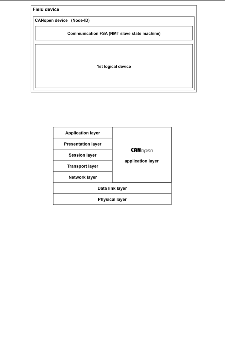
The field device shown in Figure 1 shall have at least one CANopen device. Each CANopen device
within the field device shall have at least one associated network interface comprising a data link layer
protocol (see clause 6) and a physical layer definition (see clause 5), one node-ID, and at least one
communication FSA. The first communication FSA contains the NMT slave state machine (see sub-
clause 7.3.2). Additional communication FSAs contain an emergency state machine (see sub-clause
7.2.7) and others. The definition of additional communication FSAs does not fall into the scope of this
specification. The definition is made in so-called frameworks. A CANopen device shall have at least
one and up to eight logical devices and shall not be distributed to several field devices. Each logical
device may contain a number of virtual devices and optionally a logical device FSA. A logical device
shall not be distributed to several CANopen devices. The definition of a logical device does not fall into
the scope of this specification. The definition is made in so-called device profiles (see sub-clause
4.5.1). A virtual device contains a virtual device FSA and is not distributed to several logical devices.
The definition of a virtual device does not fall into the scope of this specification. The definition is made
in so-called application profiles (see sub-clause 4.5.2). The minimum field device is shown in Figure 2.
Figure 1: Field device model
CANopen application layer and communication profile
© CiA 2011 – All rights reserved 17
Figure 2: Minimum field device
4.2 Communication reference model
4.2.1 General
Figure 3: Communication reference model
The communication concept conforms to the ISO-OSI reference model (left side of Figure 3; see
/ISO7498-1/).
4.2.2 CANopen application layer
4.2.2.1 General
The application layer describes a concept to configure and communicate real-time data as well as the
mechanisms for synchronization between CANopen devices. The functionality the application layer
offers to an application is logically divided over different service objects in the application layer. A
service object offers a specific functionality and all the related services. These services are described
in the service specification of that service object.
An application interacts by invoking services of a service object in the application layer. To realize
these services, this object exchanges data via the data link layer with (a) peer service object(s) via a
protocol. This protocol is described in the protocol specification of that service object.
4.2.2.2 Service primitives
Service primitives are the means by which the application and the application layer interact. There are
four different primitives:
• A request is issued by the application to the application layer to request a service.
• An indication is issued by the application layer to the application to report an internal event
detected by the application layer or indicate that a service is requested.
• A response is issued by the application to the application layer to respond to a previous received
indication.
CANopen application layer and communication profile
18 © CiA 2011 – All rights reserved
• A confirmation is issued by the application layer to the application to report the result of a
previously issued request.
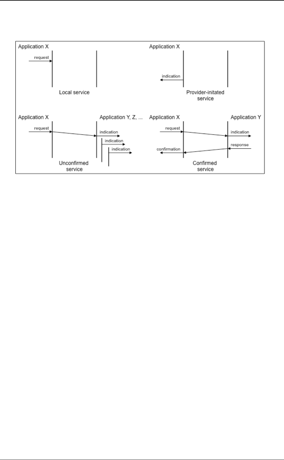
4.2.2.3 Application layer services
Figure 4: Application layer services
An application layer service defines the primitives that are exchanged between the application layer
and the co-operating applications for a particular service of a service object. The application layer
services supported by CANopen are shown in Figure 4.
• A local service involves only the local service object. The application issues a request to its local
service object that executes the requested service without communicating with (a) peer service
object(s).
• A provider-initiated service involves only the local service object. The service object (being the
service provider) detects an event not solicited by a requested service. This event is then
indicated to the application.
• An unconfirmed service involves one or more peer service objects. The application issues a
request to its local service object. This request is transferred to the peer service object(s) that
each passes it to their application as an indication. The result is not confirmed back.
• A confirmed service involves only one peer service object. The application issues a request to its
local service object. This request is transferred to the peer service object that passes it to the
other application as an indication. The other application issues a response that is transferred to
the originating service object that passes it as a confirmation to the requesting application.
Unconfirmed and confirmed services are collectively called remote services.
4.3 CANopen device model
4.3.1 General
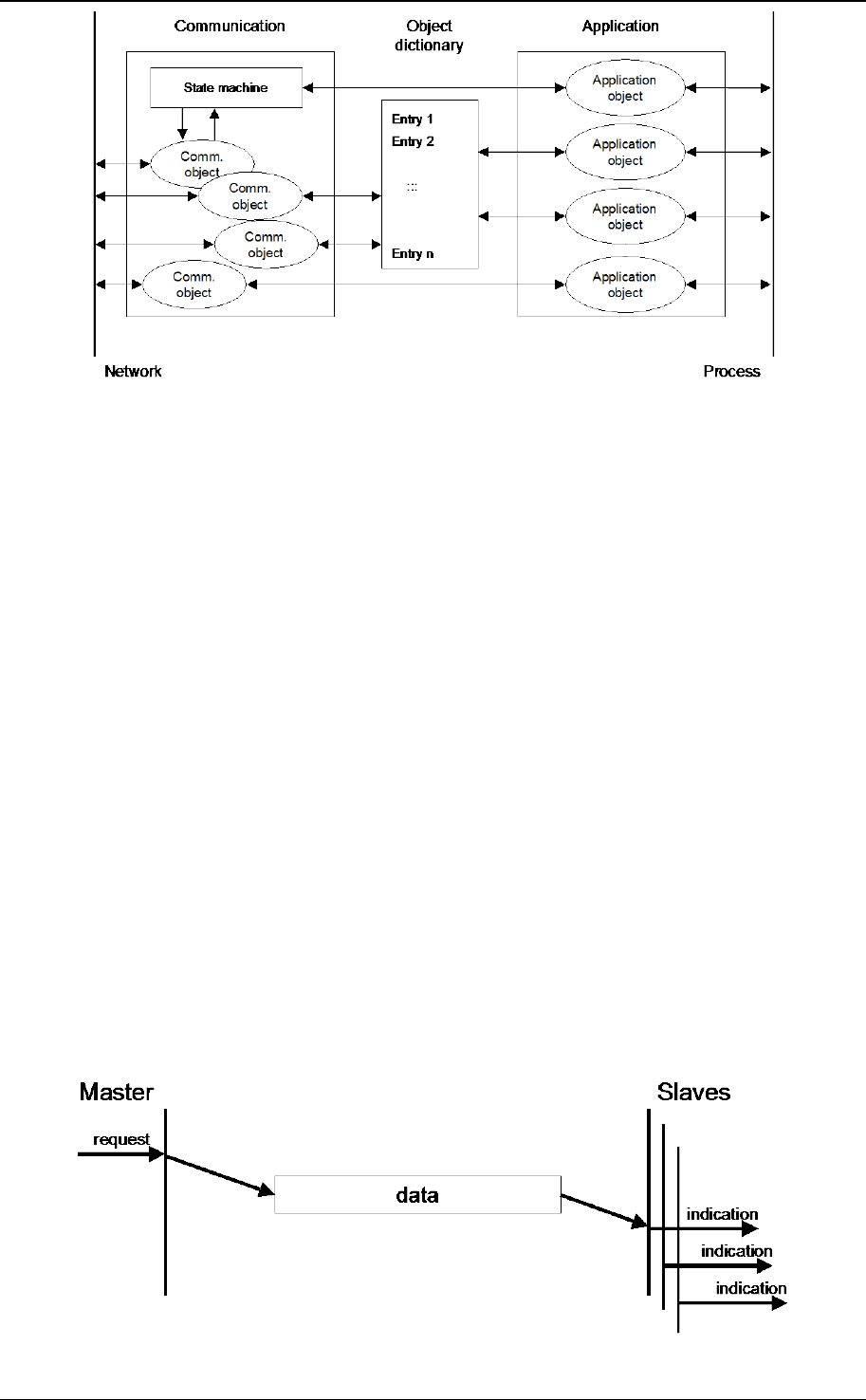
A CANopen device is structured like the following (shown in Figure 5):
• Communication – This function unit provides the communication objects and the appropriate
functionality to transport data items via the underlying network structure.
• Object dictionary – The object dictionary is a collection of all the data items which have an
influence on the behavior of the application objects, the communication objects and the state
machine used on this device.
• Application – The application comprises the functionality of the device with respect to the
interaction with the process environment.
Thus the object dictionary serves as an interface between the communication and the application.
CANopen application layer and communication profile
© CiA 2011 – All rights reserved 19
Figure 5: CANopen device model
4.4 Communication protocol sequences
4.4.1 General
The communication protocol sequences describe the different communication protocol principles and
the available modes of message transmission triggering.
The CANopen communication protocol sequences support the transmission of synchronous and
event-driven messages. By means of synchronous message transmission a network wide coordinated
data acquisition and actuation is possible. The synchronous transmission of messages is supported by
pre-defined communication objects. Synchronous messages are transmitted with respect to a pre-
defined synchronization message; event-driven messages are transmitted at any time.
Due to the event character of the underlying communication mechanism it is possible to define inhibit
times for the communication. To guarantee that no starvation on the network occurs for
communication objects with low priorities, it is possible to assign an inhibit time to the communication
object. The inhibit-time of a communication object defines the minimum time that elapses between two
consecutive invocations of a transmission service for that communication object.
With respect to their functionality, three types of communication protocol models are distinguished
• Master/Slave protocol (see sub-clause 4.4.2)
• Client/Server protocol (see sub-clause 4.4.3)
• Producer/Consumer protocol (see sub-clause 4.4.4)
4.4.2 Master/slave protocol
At any time there is exactly one CANopen device in the network serving as a master for a specific
functionality. All other CANopen devices in the network are considered as slaves. The master issues a
request and the addressed slave(s) responds(respond) if the protocol requires this behavior. Figure 6
defines the unconfirmed master/slave communication protocol. Figure 7 defines the confirmed
master/slave communication protocol.
Figure 6: Unconfirmed master/slave communication protocol

CANopen application layer and communication profile
20 © CiA 2011 – All rights reserved
Figure 7: Confirmed master/slave communication protocol
4.4.3 Client/server protocol
This is a communication protocol used between a single client and a single server. A client issues a
request (upload/download) thus triggering the server to perform a certain task. After finishing the task
the server answers the request. Figure 8 defines the client/server communication protocol.
Figure 8: Client/server communication protocol
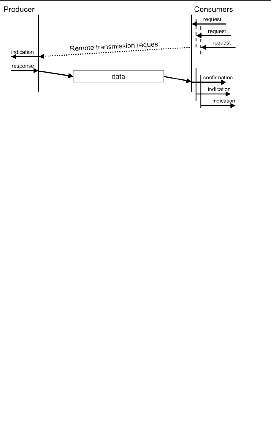
4.4.4 Producer/consumer protocol – pull/push model
The producer/consumer protocol involves a producer and zero or more consumer(s). The push model
as defined in Figure 9 is characterized by an unconfirmed protocol requested by the producer. The pull
model as defined in Figure 10 is characterized by a confirmed protocol requested by the consumer.
Figure 9: Push model
CANopen application layer and communication profile
© CiA 2011 – All rights reserved 21
Figure 10: Pull model
4.4.5 The object dictionary
The object dictionary is essentially a grouping of objects accessible via the network in an ordered pre-
defined fashion. Each object within the object dictionary is addressed using a 16-bit index and a 8-bit
sub-index.
4.5 Network system model
4.5.1 Device profile
A device profile is a description of the objects of the object dictionary of one logical device comprising
one virtual device. This description includes a functional description of the objects and a formal
description of the objects. The functional description defines the behavior of an object within the object
dictionary. The formal description defines whether an object shall be implemented or may be
implemented as well as the access from and to the CANopen network. The access depends on the
method on how an object is accessed.
4.5.2 Application profile
The application profile is a description of the objects of the object dictionary of one virtual device and
includes a network wide configuration of all CANopen devices. This description includes a functional
description of the objects and a formal description of the objects. The functional description defines
the behavior of an object within the object dictionary. The formal description defines whether an object
shall be implemented or may be implemented as well as the access from and to the network. The
access depends on the method on how an index and sub-index is accessed.

CANopen application layer and communication profile
22 © CiA 2011 – All rights reserved
5 Physical layer
5.1 Reference to OSI model
According to the OSI reference model the physical layer (shown in Figure 11) is divided into three sub-
layers:
• Medium dependent interface,
• Physical medium attachment, and
• Physical signaling.
Figure 11: Physical layer reference model
5.2 Medium dependent interface
The medium dependent interface does not fall within the scope of this specification.
5.3 Physical medium attachment
The physical medium for a CANopen device should be a differentially driven two-wire bus line with
common return according to high-speed transmission specification in /ISO11898-2/.
NOTE Other physical medium access technologies such as /ISO11898-3/ may be used.
Using the high-speed transceiver according to /ISO11898-2/ the maximum rating for V
CAN_H
and V
CAN_L
shall be +16V. Galvanic isolation between CANopen devices is optional. It is recommended to use a
transceiver that is capable of sustaining misconnection of any of the wires of the connector including
the optional V+ voltages of up to 30 V.
5.4 Physical signaling
The bit encoding/decoding and synchronization shall meet the requirements defined in /ISO11898-1/.
The bit timing shall meet the requirements defined in /ISO11898-1/ and it is recommended to follow
the definitions as given in Table 1 (the according bus length estimations are shown in Table 2). One of
these bit-rates shall be supported, additional bit-rates may be supported.
Table 1: Recommended bit timing settings
Bit rate
Nominal bit time
t
b
Valid range for
location of sample
point
Recommended
location of sample
point
1 Mbit/s 1 µs 75% to 90% 87,5%
800 kbit/s 1,25 µs 75% to 90% 87,5%
500 kbit/s 2 µs 85% to 90% 87,5%
250 kbit/s 4 µs 85% to 90% 87,5%
125 kbit/s 8 µs 85% to 90% 87,5%
50 kbit/s 20 µs 85% to 90% 87,5%
20 kbit/s 50 µs 85% to 90% 87,5%
10 kbit/s 100 µs 85% to 90% 87,5%

CANopen application layer and communication profile
© CiA 2011 – All rights reserved 23
Table 2: Estimated bus lengths
Bit rate Bus length
(1)
1 Mbit/s 25 m
800 kbit/s 50 m
500 kbit/s 100 m
250 kbit/s 250 m
125 kbit/s 500 m
50 kbit/s 1.000 m
20 kbit/s 2.500 m
10 kbit/s 5.000 m
Note 1: The bus length estimation is based on the recommended location of the sample
point.
The bus length estimation is based on a propagation delay of 5 ns/m. The delay
times of used CAN controllers, CAN transceivers, and optocouplers need to be
considered in addition.

CANopen application layer and communication profile
24 © CiA 2011 – All rights reserved
6 Data link layer
6.1 General
The described networks shall be based on a data link layer and its sub-layers according to /ISO11898-
1/.
6.2 CAN frame type
This specification is based on the CAN base frames with 11-bit CAN-ID. It is not required to support
the CAN extended frame with 29-bit identifier field.
NOTE: However, as certain applications require the usage of the CAN extended frame with 29-bit
CAN-ID the network is operated in this mode as well if it is supported at all CANopen devices.

CANopen application layer and communication profile
© CiA 2011 – All rights reserved 25
7 Application layer
7.1 Data types and encoding rules
7.1.1 General description of data types and encoding rules
To be able to exchange meaningful data across the network, it is necessary that the format of this data
and it's meaning is known by the producer and consumer(s). This specification models this by the
concept of data types.
The encoding rules define the representation of values of data types and the transfer syntax for the
representations. Values are represented as bit sequences. Bit sequences are transferred in
sequences of octets (bytes). For numerical data types the encoding is little endian style.
Applications often require data types beyond the basic data types. Using the compound data type
mechanism, it is possible to extend the list of available data types. Some general extended data types
are defined as “Visible String” or “Time of Day” for example (see sub-clause 7.1.6.3 and sub-clause
7.1.6.5). Compound data types are a means to implement user defined “DEFTYPES” in the
terminology of this specification and not “DEFSTRUCTS”.
7.1.2 Data type definitions
A data type determines a relation between values and encoding for data of that type. Names are
assigned to data types in their type definitions. The syntax of data and data type definitions is as
follows (see /EN61131-3/).
data_definition ::= type_name data_name
type_definition ::= constructor type_name
constructor ::= compound_constructor |
basic_constructor
compound_constructor ::= array_constructor |
structure_constructor
array_constructor ::= ‘ARRAY’ ‘[‘ length ‘]’ ‘OF’ type_name
structure_constructor ::= ‘STRUCT’ ‘OF’ component_list
component_list ::= component
{ ‘,’ component }
component ::= type_name component_name
basic_constructor ::= ‘BOOLEAN’ |
‘VOID’ bit_size |
‘INTEGER’ bit_size |
‘UNSIGNED’ bit_size |
‘REAL32’ |
‘REAL64’ |
‘NIL’
bit_size ::= ‘1’ | ‘2’ | <...> | ‘64’
length ::= positive_integer
data_name ::= symbolic_name
type_name ::= symbolic_name
component_name ::= symbolic_name
symbolic_name ::= letter { [ ‘_’ ] ( letter | digit ) }
positive_integer ::= ( ‘1’ | ‘2’ | <...> | ‘9’ ) { digit }
letter ::= ‘A’ | ‘B’ | <...> | ‘Z’ | ‘a’ | ‘b’ | <...> | ‘z’
digit ::= ‘0’ | ‘1’ | <...> | ‘9’
Recursive definitions shall not be used.
The data type defined by type_definition is called basic (res.~compound) when the constructor is
basic_constructor (res. compound_constructor).

CANopen application layer and communication profile
26 © CiA 2011 – All rights reserved
7.1.3 Bit sequences
7.1.3.1 Definition of bit sequences
A bit shall take the values 0 or 1. A bit sequence b is an ordered set of 0 or more bits. If a bit sequence
b contains more than 0 bits, they are denoted as b
j
, j > 0. Let b
0
, ..., b
n-1
be bits, n a positive integer.
Then
b = b
0
b
1
... b
n-1
is called a bit sequence of length |b| = n. The empty bit sequence of length 0 is denoted ε.
Examples: 10110100
b
, 1
b
, 101
b
, etc. are bit sequences.
The inversion operator (¬) on bit sequences assigns to a bit sequence
b = b
0
b
1
... b
n-1
the bit sequence
¬b = ¬b
0
¬b
1
... ¬b
n-1
Here ¬0 = 1 and ¬1 = 0 on bits.
The basic operation on bit sequences is concatenation.
Let a = a
0
... a
m-1
and b = b
0
... b
n-1
be bit sequences. Then the concatenation of a and b, denoted
ab, is
ab = a
0
... a
m-1
b
0
... b
n-1
Example: (10)(111) = 10111 is the concatenation of 10 and 111.
The following holds for arbitrary bit sequences a and b:
|ab| = |a| + |b|
and
ε
a = a
ε
= a
7.1.3.2 Transfer syntax for bit sequences
For transmission across the network a bit sequence is reordered into a sequence of octets. Here and
in the following hexadecimal notation is used for octets. Let b = b
0
...b
n-1
be a bit sequence with
n < 64. Denote k a non-negative integer such that 8(k - 1) < n < 8k. Then b is transferred in k octets
assembled as specified in Figure 12. The bits b
i
, i > n of the highest numbered octet are "do not care"
bits.
Octet 1 is transmitted first and octet k is transmitted last. Hence the bit sequence is transferred as
follows across the network:
b
7
, b
6
, ..., b
0
, b
15
, ..., b
8
, ...

CANopen application layer and communication profile
© CiA 2011 – All rights reserved 27
octet number 1. 2. k.
b
7
.. b
0
b
15
.. b
8
b
8k –1 ..
b
8k -8
Figure 12: Transfer syntax for bit sequences
Example:
Bit 9 ... Bit 0
10
b
0001
b
1100
b
2
h
1
h
C
h
= 21C
h
The bit sequence b = b
0
.. b
9
= 0011 1000 01
b
represents an UNSIGNED10 with the value
21C
h
and is transferred in two octets:
First 1C
h
and then 02
h
.
7.1.4 Basic data types
7.1.4.1 General
For basic data types “type_name” equals the literal string of the associated constructor (aka
symbolic_name), e.g.,
BOOLEAN BOOLEAN
is the type definition for the BOOLEAN data type.
7.1.4.2 NIL
Data of basic data type NIL is represented by ε.
7.1.4.3 Boolean
Data of basic data type BOOLEAN attains the values TRUE or FALSE. The values are represented as
bit sequences of length 1. The value TRUE (res. FALSE) is represented by the bit sequence 1 (res. 0).
7.1.4.4 Void
Data of basic data type VOIDn is represented as bit sequences of length n bit. The value of data of
type VOIDn is undefined. The bits in the sequence of data of type VOIDn shall either be specified
explicitly or else marked "do not care".
Data of type VOIDn is useful for reserved fields and for aligning components of compound values on
octet boundaries.
7.1.4.5 Unsigned Integer
Data of basic data type UNSIGNEDn has values in the non-negative integers. The value range is 0, ...,
2
n
-1. The data is represented as bit sequences of length n. The bit sequence
b = b
0
...b
n-1
is assigned the value
UNSIGNEDn(b) = b
n-1
2
n-1
+ ...+ b
1
2
1
+ b
0
2
0
Note that the bit sequence starts on the left with the least significant byte.
Example: The value 266 = 10A
h
with data type UNSIGNED16 is transferred in two octets
across the bus, first 0A
h
and then 01
h
.

CANopen application layer and communication profile
28 © CiA 2011 – All rights reserved
The UNSIGNEDn data types transferred are defined in Figure 13.
octet number 1. 2. 3. 4. 5. 6. 7. 8.
UNSIGNED8
b
7
..b
0
UNSIGNED16 b
7
..b
0
b
15
..b
8
UNSIGNED24 b
7
..b
0
b
15
..b
8
b
23
..b
16
UNSIGNED32 b
7
..b
0
b
15
..b
8
b
23
..b
16
b
31
..b
24
UNSIGNED40 b
7
..b
0
b
15
..b
8
b
23
..b
16
b
31
..b
24
b
39
..b
32
UNSIGNED48 b
7
..b
0
b
15
..b
8
b
23
..b
16
b
31
..b
24
b
39
..b
32
b
47
..b
40
UNSIGNED56 b
7
..b
0
b
15
..b
8
b
23
..b
16
b
31
..b
24
b
39
..b
32
b
47
..b
40
b
55
..b
48
UNSIGNED64 b
7
..b
0
b
15
..b
8
b
23
..b
16
b
31
..b
24
b
39
..b
32
b
47
..b
40
b
55
..b
48
b
63
..b
56
Figure 13: Transfer syntax for data type UNSIGNEDn
7.1.4.6 Signed Integer
Data of basic data type INTEGERn has values in the integers. The value range is from -2
n-1
to 2
n-1
-
1. The data is represented as bit sequences of length n. The bit sequence
b = b
0
.. b
n-1
is assigned the value
INTEGERn(b) = b
n-2
2
n-2
+ ...+ b
1
2
1
+ b
0
2
0
if b
n-1
= 0
and, performing two's complement arithmetic,
INTEGERn(b) = - INTEGERn(^b) - 1 if b
n-1
= 1
Note that the bit sequence starts on the left with the least significant bit.
Example: The value –266 = FEF6
h
with data type INTEGER16 is transferred in two octets
across the bus, first F6
h
and then FE
h
.
The INTEGERn data types transferred are defined in Figure 14.
octet number
1.
2.
3.
4.
5.
6.
7.
8.
INTEGER8 b
7
..b
0
INTEGER16 b
7
..b
0
b
15
..b
8
INTEGER24 b
7
..b
0
b
15
..b
8
b
23
..b
16
INTEGER32 b
7
..b
0
b
15
..b
8
b
23
..b
16
b
31
..b
24
INTEGER40 b
7
..b
0
b
15
..b
8
b
23
..b
16
b
31
..b
24
b
39
..b
32
INTEGER48 b
7
..b
0
b
15
..b
8
b
23
..b
16
b
31
..b
24
b
39
..b
32
b
47
..b
40
INTEGER56 b
7
..b
0
b
15
..b
8
b
23
..b
16
b
31
..b
24
b
39
..b
32
b
47
..b
40
b
55
..b
48
INTEGER64 b
7
..b
0
b
15
..b
8
b
23
..b
16
b
31
..b
24
b
39
..b
32
b
47
..b
40
b
55
..b
48
b
63
..b
56
Figure 14: Transfer syntax for data type INTEGERn
7.1.4.7 Floating-Point Numbers
Data of basic data types REAL32 and REAL64 have values in the real numbers.
The data type REAL32 is represented as bit sequence of length 32. The encoding of values follows
/IEEE754/. The transfer syntax is specified in Figure 15.
The data type REAL64 is represented as bit sequence of length 64. The encoding of values follows
/IEEE754/.

CANopen application layer and communication profile
© CiA 2011 – All rights reserved 29
A bit sequence of length 32 either has a value (finite non-zero real number,
+
0,
+
_) or is NaN (not-a-
number). The bit sequence
b = b
0
b
31
is assigned the value (finite non-zero number)
REAL32(b) = (-1)
S
2
E - 127
(1 + F)
Here
S = b
31
is the sign.
E = b
30
2
7
+ + b
23
2
0
, 0 < E < 255, is the un-biased exponent.
F = 2
-23
(b
22
2
22
+ + b
1
2
1
+ b
0
2
0
) is the fractional part of the number.
E = 0 is used to represent
+
0. E = 255 is used to represent infinities and NaN's.
Note that the bit sequence starts on the left with the least significant bit.
Example:
6,25 = 2
E -127
(1 + F) with
E =129 =2
7
+2
0
and
F = 2
-1
+2
-4
= 2
-23
(2
22
+2
19
) hence the number is represented as:
S E F
b
31
b
30
.. b
23
b
22
.. b
0
0 100 0000 1
b
100 1000 0000 0000 0000 0000
b
6,25 = b
0
.. b
31
= 0000 0000 0000 0000 0001 0011 0000 0010
b
It is transferred in the following order:
octet number 1. 2. 3. 4.
REAL32 00
h
00
h
C8
h
40
h
b
7
..b
0
b
15
..b
8
b
23
..b
16
b
31
..b
24
Figure 15: Transfer syntax of data type REAL32
7.1.5 Compound data types
Type definitions of compound data types expand to a unique list of type definitions involving only basic
data types. Correspondingly, data of compound type ´type_name´ are ordered lists of component data
named ´component_name_i´ of basic type ´basic_type_i´.
Compound data types constructors are ARRAY and STRUCT OF.
STRUCT OF
basic_type_1 component_name_1,
basic_type_2 component_name_2,
basic_type_N component_name_N
type_name
ARRAY [ length ] OF basic_type type_name
The bit sequence representing data of compound type is obtained by concatenating the bit sequences
representing the component data.

CANopen application layer and communication profile
30 © CiA 2011 – All rights reserved
Assume that the components ´component_name_i´ are represented by their bit sequences
b(i)
,
for i = 1, ,N
Then the compound data is represented by the concatenated sequence
b
0
(1) .. b
n-1
(1) .. b
n-1
(N).
Example:
Consider the data type
STRUCT OF
INTEGER10 x,
UNSIGNED5 u
NewData
Assume x = - 423 = 259
h
and u = 30 = 1E
h
. Let b(x) and b(u) denote the bit sequences
representing the values of x and u, respectively. Then:
b(x) = b
0
(x) .. b
9
(x) = 1001101001
b
b(u) = b
0
(u) .. b
4
(u) = 01111
b
b(xu) = b(x) b(u) = b
0
(xu) .. b
14
(xu) = 1001101001 01111
b
The value of the structure is transferred with two octets, first 59
h
and then 7A
h
.
7.1.6 Extended data types
7.1.6.1 General
The extended data types consist of the basic data types and the compound data types defined in the
following subsections.
7.1.6.2 Octet String
The data type OCTET_STRINGlength is defined below; length is the length of the octet string.
ARRAY [ length ] OF UNSIGNED8 OCTET_STRINGlength
7.1.6.3 Visible String
The data type VISIBLE_STRINGlength is defined below. The admissible values of data of type
VISIBLE_CHAR are 0
h
and the range from 20
h
to 7E
h
. The data are interpreted as ISO 646-1973(E) 7-
bit coded characters. length is the length of the visible string.
UNSIGNED8 VISIBLE_CHAR
ARRAY [ length ] OF VISIBLE_CHAR VISIBLE_STRINGlength
There is no 0
h
necessary to terminate the string.
7.1.6.4 Unicode String
The data type UNICODE_STRINGlength is defined below; length is the length of the unicode string.
ARRAY [ length ] OF UNSIGNED16 UNICODE_STRINGlength
7.1.6.5 Time of Day
The data type TIME_OF_DAY represents absolute time. It follows from the definition and the encoding
rules that TIME_OF_DAY is represented as bit sequence of length 48.
Component ms is the time in milliseconds after midnight. Component days is the number of days since
January 1, 1984.
STRUCT OF
UNSIGNED28 ms,
VOID4 reserved,
UNSIGNED16 days
TIME_OF_DAY
7.1.6.6 Time Difference
The data type TIME_DIFFERENCE represents a time difference. It follows from the definition and the
encoding rules that TIME_DIFFERENCE is represented as bit sequence of length 48.

CANopen application layer and communication profile
© CiA 2011 – All rights reserved 31
Time differences are sums of numbers of days and milliseconds. Component ms is the number
milliseconds. Component days is the number of days.
STRUCT OF
UNSIGNED28 ms,
VOID4 reserved,
UNSIGNED16 days
TIME_DIFFERENCE
7.1.6.7 Domain
Domains are used to transfer an arbitrary large block of data from a client to a server and vice versa.
The content of a data block is application specific and does not fall within the scope of this
specification.
7.2 Communication objects
7.2.1 General
The communication objects are described by the services and protocols.
All services are described in a tabular form that contains the parameters of each service primitive that
is defined for that service. The primitives that are defined for a particular service determine the service
type (e.g. unconfirmed, confirmed, etc.).
All services assume that no failures occur in the data link layer and physical layer of CAN. These
failures are resolved by the application and fall not in the scope of this specification.
7.2.2 Process data object (PDO)
7.2.2.1 General
The real-time data transfer is performed by means of "Process Data Objects (PDO)". The transfer of
PDO is performed with no protocol overhead.
The PDO correspond to objects in the object dictionary and provide the interface to the application
objects. Data type and mapping of application objects into a PDO is determined by a corresponding
default PDO mapping structure within the object dictionary. If variable PDO mapping is supported the
number of PDO and the mapping of application objects into a PDO may be transmitted to a CANopen
device during the configuration process (see clause 7.3.1) by applying the SDO services to the
corresponding objects of the object dictionary.
Number and length of PDO of a CANopen device is application specific and may be specified within
the device profile or application profile.
There are two kinds of use for PDO. The first is data transmission and the second data reception. It is
distinguished in Transmit-PDO (TPDO) and Receive-PDO (RPDO). CANopen devices supporting
TPDO are PDO producer and CANopen devices supporting RPDO are called PDO consumer. PDO
are described by the PDO communication parameter and the PDO mapping parameter. The structure
of these data types is explained in clause 7.4.8. The PDO communication parameter describes the
communication capabilities of the PDO. The PDO mapping parameter contains information about the
contents of the PDO.
For each PDO the pair of communication and mapping parameter is mandatory. The objects
introduced above are described in clause 7.4.
The definition of PDO within a device profile always refers to the 1
st
logical device within a CANopen
device. If the definitions are used for the 2
nd
logical device the PDO number in the CANopen device
used shall be the PDO number as defined in the device profile increased by the value of 64 (40
h
) as
defined in Table 3.
NOTE: The number of PDOs is not limited for a logical device, for example a CANopen device with
only one logical device may have 512 PDOs.

CANopen application layer and communication profile
32 © CiA 2011 – All rights reserved
Table 3: Example PDO number calculation
Logical device in
CANopen device
PDO number in CANopen device PDO number in device profile
1
st
logical device
PDO number + 0
(PDO1to PDO64)
PDO number
(PDO1 to PDO64)
2
nd
logical device
PDO number + 64
(PDO65 to PDO128)
PDO number
(PDO1 to PDO64)
3
rd
logical device
PDO number + 128
(PDO129 to PDO192)
PDO number
(PDO1 to PDO64)
4
th
logical device
PDO number + 192
(PDO193 to PDO256)
PDO number
(PDO1 to PDO64)
5
th
logical device
PDO number + 256
(PDO257 to PDO320)
PDO number
(PDO1 to PDO64)
6
th
logical device
PDO number + 320
(PDO321 to PDO384)
PDO number
(PDO1 to PDO64)
7
th
logical device
PDO number + 384
(PDO385 to PDO448)
PDO number
(PDO1 to PDO64)
8
th
logical device
PDO number + 448
(PDO449 to PDO512)
PDO number
(PDO1 to PDO64)
7.2.2.2 Transmission modes
The following PDO transmission modes are distinguished:
• Synchronous transmission
• Event-driven transmission
In order to synchronize CANopen devices a synchronization object (SYNC object) is transmitted
periodically by a synchronization application. The SYNC object is represented by a pre-defined
communication object (see sub-clause 7.2.5). In Figure 16 the principle of synchronous and event-
driven transmission is shown. Synchronous PDOs are transmitted within a pre-defined time-window
immediately after the SYNC object.
Figure 16: Synchronous and event-driven transmission
The transmission type parameter of a PDO specifies the transmission mode as well as the triggering
mode.
For synchronous TPDOs the transmission type also specifies the transmission rate in form of a factor
based on the basic SYNC object transmission period. A transmission type of 0 means that the
message shall be transmitted after occurrence of the SYNC but acyclic (not periodically), only if an
event occurred before the SYNC. The transmission type 1 means that the message shall be
transmitted with every SYNC object. A transmission type of n means that the message shall be
transmitted with every n-th SYNC object. Event-driven TPDOs are transmitted without any relation to
the SYNC object.

CANopen application layer and communication profile
© CiA 2011 – All rights reserved 33
The data of synchronous RPDOs received after the occurrence of the SYNC object is passed to the
application with the occurrence of the following SYNC, independent of the transmission rate specified
by the transmission type. The data of event-driven RPDOs is passed directly to the application.
7.2.2.3 Triggering modes
Three message-triggering modes are distinguished:
- Event- and timer-driven
Message transmission is either triggered by the occurrence of an application-specific event
specified in the device profile, application profile or manufacturer-specific, or if a specified time
(event-time) has elapsed without occurrence of an event.
- Remotely requested
The transmission of an event-driven PDO is initiated on receipt of a RTR initiated by a PDO
consumer.
- Synchronously triggered
Message transmission is triggered by the occurrence of the SYNC object. The trigger condition
is the number of Sync and optionally an internal event.
7.2.2.4 PDO services
7.2.2.4.1 General
PDO transmission follows the producer/consumer relationship as described in sub-clause 4.4.4.
Attributes:
- PDO number: PDO number [1..512] for every user type on the local device
- user type: one of the values {consumer, producer}
- data type: according to the PDO mapping
- inhibit-time: n*100 µs, n > 0
7.2.2.4.2 Service PDO write
The service PDO write is according to the push model. There are zero or more consumers of the PDO.
The PDO shall have exactly one producer.
Through this service the producer of the PDO sends the data of the mapped application objects to the
consumer(s). The parameters for this service are defined in Table 4.
Table 4: Service PDO write
Parameter Request / Indication
Argument
PDO number
Data
Mandatory
mandatory
mandatory

CANopen application layer and communication profile
34 © CiA 2011 – All rights reserved
7.2.2.4.3 Service PDO read
The service PDO read is according to the pull model. There are one or more consumers of the PDO.
The PDO shall have exactly one producer.
Through this service the consumer of the PDO requests the producer to supply the data of the
mapped application objects. The service is confirmed. The remote result parameter will confirm the
value. The parameters for this service are defined in Table 5.
Table 5: Service PDO read
Parameter Request / Indication Response / Confirm
Argument
PDO number
Remote result
Data
Mandatory
mandatory
Mandatory
mandatory
7.2.2.5 PDO protocol
7.2.2.5.1 Protocol PDO write
The request for the service PDO write is unconfirmed. The PDO producer shall send the process data
within a PDO to the network. There may be 0 to n PDO consumers. At the PDO consumer(s) the
reception of a valid PDO is indicated. Figure 17 defines the PDO write protocol.
Process data: L bytes of application data
Figure 17: Protocol PDO write

CANopen application layer and communication profile
© CiA 2011 – All rights reserved 35
7.2.2.5.2 Protocol PDO read
The service for a PDO read request is confirmed. One or more PDO consumer shall transmit a RTR to
the network. At the reception of the RTR the PDO producer for the requested PDO shall transmit the
PDO. At all PDO consumers for this PDO the reception shall be indicated. There may be 1 to n PDO
consumers. The read service is optional and depends on the hardware capabilities. Figure 18
specifies the PDO read protocol.
Process data: L bytes of application data
Figure 18: Protocol PDO read
7.2.3 Multiplex PDO (MPDO)
7.2.3.1 General
An MPDO provides direct write access to objects of a CANopen device's object dictionary. The size of
the data of these objects is limited to a maximum of 4 bytes.
There are two kinds of use for the MPDO. The first is the destination address mode (DAM) MPDO and
the second is the source address mode (SAM) MPDO. CANopen devices supporting to receipt
MPDOs are MPDO consumers and CANopen devices supporting to transmit MPDOs are MPDO
producers.
The MPDOs correspond to objects in the object dictionary and provide the interface to the application
objects.
7.2.3.2 MPDO address modes
7.2.3.2.1 Destination address mode (DAM)
A multiplexer (see 7.2.3.4.1) identifies the object in the MPDO consumer’s object dictionary. A DAM-
MPDO may be received either by all consumers of this MPDO simultaneously or by a single consumer
. Since the used write service is unconfirmed, an EMCY message is generated if the object does not
exist.
The transmission of an MPDO at the MPDO producer shall be event-driven and shall not be timer-
driven, remotely requested, synchronously triggered.
7.2.3.2.2 Source address mode (SAM)
A multiplexer of the MPDO refer to the MPDO producer. Only one MPDO producer of this type is
allowed for each CANopen device. The transmission shall be event-driven and shall not be timer-
driven, remotely requested, synchronously triggered. The MPDO producer may use a scanner list in
order to know which object shall be send. The MPDO consumers may use a dispatcher list in order to
know which source multiplexer references to what destination multiplexer.

CANopen application layer and communication profile
36 © CiA 2011 – All rights reserved
7.2.3.3 MPDO service
7.2.3.3.1 General
MPDO transmission follows the producer/consumer relationship as described in sub-clause 4.4.4.
Attributes:
- PDO number: PDO number [1..512] for every user type on the local device
- user type: one of the values {consumer, producer}
- multiplexer: containing index and sub-index of type STRUCTURE OF
UNSIGNED16, UNSIGNED8, with index specifying an object of the
CANopen device's object dictionary and sub-index specifying a
component of a CANopen device's object dictionary object
- address type: one of the values {source, destination}
- Node-ID of the consumer or producer
- inhibit-time: n*100 µs, n > 0
7.2.3.3.2 Service MPDO write
The service MPDO write is according to the push model. There are zero or more consumers of the
MPDO. The MPDO shall have exactly one producer.
The parameters for this service are defined in Table 6.
Table 6: Service MPDO write
Parameter Request / Indication
Argument
PDO number
Address type
Node-ID
Multiplexer
Data
Mandatory
mandatory
mandatory
mandatory
mandatory
mandatory
7.2.3.4 MPDO protocol
7.2.3.4.1 Protocol MPDO write
The request for the service MPDO write is unconfirmed. The MPDO producer shall send the process
data within a MPDO to the network. There may be 0 to n MPDO consumers, depending on the given
node-ID. At the MPDO consumer(s) the reception of a valid PDO shall be indicated. Figure 19
specifies the MPDO write protocol.

CANopen application layer and communication profile
© CiA 2011 – All rights reserved 37
• f: address type
0: Source addressing
1: Destination addressing
• addr: node-ID of the MPDO consumer in destination addressing or MPDO producer in source
addressing.
0: Shall be reserved in source addressing mode. Shall address all CANopen devices in the
network that are configured for MPDO reception in destination addressing mode.
1..127: Shall address the CANopen device in the network with the very same node-ID.
• m: multiplexer. It represents the index/sub-index of the process data to be transferred by the
MPDO. Depending on the address type the index/sub-index shall be used to identify the data from
the transmitting CANopen device (source addressing) or to identify the data on the receiving
CANopen device (destination addressing).
• d: process data. Data length lower than 4 bytes is filled up to fit 32-bit.
Figure 19: Protocol MPDO write
7.2.4 Service data object (SDO)
7.2.4.1 General
A SDO is providing direct access to object entries of a CANopen device's object dictionary. As these
object entries may contain data of arbitrary size and data type. SDOs may be used to transfer multiple
data sets (each containing an arbitrary large block of data) from a client to a server and vice versa.
The client shall control via a multiplexer (index and sub-index of the object dictionary) which data set
shall be transferred. The content of the data set is defined within the object dictionary.
Basically an SDO is transferred as a sequence of segments. Prior to transferring the segments there is
an initialization phase where client and server prepare themselves for transferring the segments. For
SDOs, it is also possible to transfer a data set of up to four bytes during the initialization phase. This
mechanism is called SDO expedited transfer.
Optionally an SDO may be transferred as a sequence of blocks where each block may consist of a
sequence of up to 127 segments containing a sequence number and the data. Prior to transferring the
blocks there shall be an initialization phase where client and server may prepare themselves for
transferring the blocks and negotiating the number of segments in one block. After transferring the
blocks there shall be a finalization phase where client and server may verify the correctness of the
previous data transfer by comparing checksums derived from the data set. The transfer type
mentioned above is called SDO block transfer, which is faster than the segmented transfer for a large
set of data.
In SDO block upload it is possible that the size of the data set does not justify the use of a block
transfer because of the implied protocol overhead. In these cases a support for a fallback to the SDO
normal (segmented) or SDO expedited transfer in initialization phase may be implemented. As the
assumption of the minimal data set size for which an SDO block transfer outperforms the other
transfer types depends on various parameters the client indicates this threshold value in bytes to the
server in initialization phase.
For the SDO block transfer a Go-Back-n ARQ scheme is used to confirm each block:
• After SDO block download the server indicates the client the last successfully received segment of
this SDO block transfer by acknowledging this segment sequence number. Doing this the server
implicitly acknowledges all segments preceding this segment. The client shall start the following

CANopen application layer and communication profile
38 © CiA 2011 – All rights reserved
SDO block transfer with the retransmission of all not acknowledged data. Additionally the server
shall indicate the number of segments per SDO block for the next SDO block transfer.
• After SDO block upload the client indicates the server the last successfully received segment of
the SDO block transfer by acknowledging this segment sequence number. Doing this the client
implicitly acknowledges all segments preceding this segment. The server shall start the following
SDO block transfer with the retransmission of all not acknowledged data. Additionally the client
shall indicate the number of segments per SDO block for the next SDO block transfer.
Always the client initiates an SDO transfer for any type of transfer. The owner of the accessed object
dictionary is the server of the SDO. Either the client or the server may take the initiative to abort the
transfer of an SDO.
By means of an SDO a peer-to-peer communication channel between two CANopen devices is
established. A CANopen device may support more than one SDO. One supported Server-SDO is the
default case (Default SDO).
SDOs are described by the SDO communication parameter record. The structure of this data type is
explained in sub-clause 7.4.8. The SDO communication parameter describes the communication
capabilities of the SSDO and CSDO.
For each SDO the communication parameters are mandatory. If only one SSDO exist the
communication parameters may be omitted. The objects mentioned above are described in sub-
clause 7.4.
7.2.4.2 SDO services
7.2.4.2.1 General
The model for the SDO communication is the Client/Server model as described in sub-clause 4.4.3.
Attributes:
- SDO number: SDO number [1..128] for every user type on the local device
- user type: one of the values {client, server}
- mux data type: multiplexer containing index and sub-index of type STRUCTURE OF
UNSIGNED16, UNSIGNED8, with index specifying an object of the
CANopen device's object dictionary and sub-index specifying a
component of a CANopen device's object dictionary object
- transfer type: depends on the length of data to transfer: expedited, normal
(segmented) or block for up to 4 data bytes; normal (segmented) or
block for more than 4 data bytes
- data type: according to the referenced index and sub-index
The following services may be applied onto an SDO depending on the application requirements:
• SDO download, which is subdivided into
- SDO download initiate
- SDO download segment
• SDO upload, which is subdivided into
- SDO upload initiate
- SDO upload segment
• SDO abort transfer
When using the SDO normal (segmented) download and SDO normal (segmented) upload services,
the communication software will be responsible for transferring the SDO as a sequence of segments.
SDO expedited transfer shall be supported. SDO segmented transfer shall be supported if objects
larger than 4 Bytes are supported. Optionally the following SDO services for doing an SDO block
transfer with higher bus utilization and performance for a large data set size may be implemented:
• SDO block download, which is subdivided into
- SDO block download initiate
- SDO block download block
- SDO block download end

CANopen application layer and communication profile
© CiA 2011 – All rights reserved 39
• SDO block upload, which is subdivided into
- SDO block upload initiate
- SDO block upload block
- SDO block upload end
When using the SDO block download and SDO block upload services, the communication software
will be responsible for transferring the data as a sequence of blocks.
In SDO block upload protocol a support for a switch to SDO upload protocol in SDO block upload
initiate may be implemented to increase transfer performance for data which size does not justify
using the protocol overhead of the SDO block upload protocol.
To abort an SDO block transfer the SDO abort transfer service is used.
7.2.4.2.2 Service SDO download
The client is using the service SDO download for transferring data from the client to the server (owner
of the object dictionary). The data, the multiplexer (index and sub-index) of the data set, and its size
are indicated to the server. The parameters for this service are defined in Table 7.
The service is confirmed. The remote result parameter will indicate the success or failure of the
request. In case of a failure, optionally the reason is confirmed.
The SDO download consists of at least the SDO download initiate service and optionally of the SDO
download segment services (data length > 4 bytes).
Table 7: Service SDO download
Parameter Request / Indication Response / Confirm
Argument
SDO number
Multiplexer
Size
Data
Remote result
Success
Failure
Reason
Mandatory
mandatory
mandatory
optional
mandatory
Mandatory
selection
selection
optional
7.2.4.2.3 Service SDO download initiate
The client requests the server to prepare downloading of data by using the SDO download initiate
service. Optionally the size of the data to be downloaded is indicated to the server. The parameters for
this service are defined in Table 8.
The multiplexer of the data set and the transfer type are indicated to the server. In case of an SDO
expedited download, the data of the data set identified by the multiplexer and size is indicated to the
server.

CANopen application layer and communication profile
40 © CiA 2011 – All rights reserved
Table 8: Service SDO download initiate
Parameter Request / Indication Response / Confirm
Argument
SDO number
Multiplexer
Transfer type
Normal
Expedited
Size
Data
Remote result
Success
Mandatory
mandatory
mandatory
mandatory
selection
selection
optional
mandatory
Mandatory
mandatory
The service is confirmed. The remote result parameter will indicate the success of the request. In case
of a failure, an SDO abort transfer request shall be initiated. In the case of a successful SDO
expedited download of a multiplexed DOMAIN, this service concludes the download of the data set
identified by multiplexer.
7.2.4.2.4 Service SDO download segment
The client transfers the segmented data to the server by using the SDO download service. The
segment data and optionally its size are indicated to the server. The continue parameter indicates the
server whether there are still more segments to be downloaded or that this was the last segment to be
downloaded. The parameters for this service are defined in Table 9.
Table 9: Service SDO download segment
Parameter Request / Indication Response / Confirm
Argument
SDO number
Continue
More
Last
Size
Data
Remote result
Success
Mandatory
mandatory
mandatory
selection
selection
mandatory
mandatory
Mandatory
mandatory
The service is confirmed. The remote result parameter will indicate the success of the request. In case
of a failure, an SDO abort transfer request shall be initiated. In case of success, the server has
accepted the segment data and is ready to accept the next segment. There shall be at most one SDO
download segment service outstanding for an SDO transfer.
A successful SDO download initiate service with segmented transfer type shall have been executed
prior to this service.

CANopen application layer and communication profile
© CiA 2011 – All rights reserved 41
7.2.4.2.5 Service SDO upload
The client is using the service SDO upload for transferring the data from the server (owner of the
object dictionary) to the client. The multiplexer (index and sub-index) of the data set is indicated to the
server. The parameters for this service are defined in Table 10.
The SDO upload consists of at least the SDO upload initiate service and optional of SDO upload
segment services (data length > 4 bytes).
Table 10: Service SDO upload
Parameter Request / Indication Response / Confirm
Argument
SDO number
Multiplexer
Remote result
Success
Size
Data
Failure
Reason
Mandatory
mandatory
mandatory
Mandatory
selection
optional
mandatory
selection
optional
The service is confirmed. The remote result parameter will indicate the success or failure of the
request. In case of a failure, optionally the reason is confirmed. In case of success, the data and its
size are confirmed.
7.2.4.2.6 Service SDO upload initiate
The client requests the server to prepare the data for uploading by using the SDO upload initiate
service. The multiplexer (index and sub-index) of the data set whose upload is initiated is indicated to
the server. The parameters for this service are defined in Table 11.
The service is confirmed. The remote result parameter will indicate the success of the request. In case
of a failure, an SDO abort transfer request shall be executed. In the case of success, the size of the
data is confirmed. In case of successful SDO expedited upload, this service concludes the upload of
the data set identified by multiplexer and the corresponding data is confirmed.

CANopen application layer and communication profile
42 © CiA 2011 – All rights reserved
Table 11: Service SDO upload initiate
Parameter Request / Indication Response / Confirm
Argument
SDO number
Multiplexer
Remote result
Success
Multiplexer
Transfer type
Normal
Expedited
Size
Data
Mandatory
mandatory
mandatory
Mandatory
mandatory
mandatory
mandatory
selection
selection
optional
mandatory
7.2.4.2.7 Service SDO upload segment
The client requests the server to supply the data of the next segment by using the SDO upload
segment service. The continue parameter indicates the client whether there are still more segments to
be uploaded or that this was the last segment to be uploaded. There shall be at most one SDO upload
segment service outstanding for an SDO. The parameters for this service are defined in Table 12.
The service is confirmed. The remote result parameter will indicate the success of the request. In case
of a failure, an SDO abort transfer request shall be initiated. In case of success, the segment data and
optionally its size are confirmed.
A successful SDO upload initiate service with normal (segmented) transfer type shall be executed
prior to this service.
Table 12: Service SDO upload segment
Parameter Request / Indication Response / Confirm
Argument
SDO number
Remote result
Success
Continue
More
Last
Size
Data
Mandatory
mandatory
Mandatory
mandatory
mandatory
selection
selection
mandatory
mandatory

CANopen application layer and communication profile
© CiA 2011 – All rights reserved 43
7.2.4.2.8 Service SDO block download
The client is using the service SDO block download for transferring the data from the client to the
server (owner of the object dictionary). The data, the multiplexer (index and sub-index) of the data set
and optionally its size is indicated to the server. The parameters for this service are defined in Table
13.
The service is confirmed. The remote result parameter will indicate the success or failure of the
request. In case of a failure, optionally the reason is confirmed.
Table 13: Service SDO block download
Parameter Request / Indication Response / Confirm
Argument
SDO number
Multiplexer
Size
Data
Remote result
Success
Failure
Reason
Mandatory
mandatory
mandatory
optional
mandatory
Mandatory
selection
selection
optional
7.2.4.2.9 Service SDO block download initiate
The client requests the server to prepare for download by using the SDO block download initiate
service. The parameters for this service are defined in Table 14.
The multiplexer of the data set and optionally the size are indicated to the server.
Both the client and the server are indicating their ability and demand to verify the complete transfer
with a checksum in SDO block download end.
Table 14: Service SDO block download initiate
Parameter Request / Indication Response / Confirm
Argument
SDO number
CRC ability
yes
no
Multiplexer
Size
Remote result
Success
CRC ability
yes
no
Blksize
Mandatory
mandatory
mandatory
selection
selection
mandatory
optional
Mandatory
mandatory
mandatory
selection
selection
mandatory

CANopen application layer and communication profile
44 © CiA 2011 – All rights reserved
The service is confirmed. The remote result parameter will indicate the success of the request, the
number of segments per block the server is able to receive and its ability and demand to verify the
complete transfer with a checksum. In case of a failure, an SDO abort transfer service shall be
initiated.
7.2.4.2.10 Service SDO block download sub-block
The client transfers the data of the next block to the server by using the SDO block download sub-
block service. The block data is transferred to the server by a sequence of segments. Each segment
consists of the data and a sequence number starting by 1, which is increased for each segment by 1
up to blksize. The parameter blksize is negotiated between server and client in the SDO block
download initiate service and may be changed by the server with each confirmation for a block
transfer. The continue parameter indicates the server whether to stay in the SDO block download sub-
block phase or to change in the SDO block download end phase. The parameters for this service are
defined in Table 15.
Table 15: Service SDO block download sub-block
Parameter Request / Indication Response / Confirm
Argument
SDO number
Continue
More
Last
Data
Remote result
Success
Ackseq
Blksize
Mandatory
mandatory
mandatory
selection
selection
mandatory
Mandatory
mandatory
mandatory
mandatory
The service is confirmed. The remote result parameter will indicate the success of the request. In case
of a success the ackseq parameter indicates the sequence number of the last segment the server has
received successfully. If this number does not correspond with the sequence number of the last
segment sent by the client during this block transfer the client shall retransmit all segments discarded
by the server within the next block transfer. In case of a fatal failure, an SDO abort transfer service
shall be initiated. In case of success, the server has accepted all acknowledged segment data and is
ready to accept the next block. There shall be at most one SDO block download sub-block service
outstanding for an SDO transfer.
A successful SDO block download initiate service shall be executed prior to this service.
7.2.4.2.11 Service SDO block download end
The client indicates the end of the transfer to the server by using the SDO block download end
service. The number of bytes not containing valid data in the last transmitted segments is indicated to
the server. The parameters for this service are defined in Table 16.
If both the server and the client have indicated their ability and demand to check the complete transfer
with a checksum in SDO block download initiate the client indicates the checksum of the transferred
data to the server. The server also shall generate the checksum which shall be compared with the one
generated by the client.

CANopen application layer and communication profile
© CiA 2011 – All rights reserved 45
Table 16: Service SDO block download end
Parameter Request / Indication Response / Confirm
Argument
SDO number
Valid_data
Checksum
Remote result
Success
Mandatory
mandatory
mandatory
conditional,
mandatory if negotiated
Mandatory
mandatory
The service is confirmed. The remote result parameter will indicate the success of the request
(matching checksums between client and server if negotiated) and concludes the download of the
data set. In case of a failure, an SDO abort transfer service shall be initiated.
7.2.4.2.12 Service SDO block upload
The client is using the service SDO block upload to transfer the data from the server (owner of the
object dictionary) to the client. The multiplexer (index and sub-index) of the data set requested is
indicated to the server. The parameters for this service are defined in Table 17.
The service is confirmed. The remote result parameter will indicate the success or failure of the
request. In case of a failure, optionally the reason is confirmed. In case of a success, the data and
optionally its size is confirmed.
Table 17: Service SDO block upload
Parameter Request / Indication Response / Confirm
Argument
SDO number
Multiplexer
Remote result
Success
Size
Data
Failure
Reason
Mandatory
mandatory
mandatory
Mandatory
selection
optional
mandatory
selection
optional
7.2.4.2.13 Service SDO block upload initiate
The client requests the server to prepare for uploading data by using the SDO block upload initiate
service. The multiplexer of the data set whose upload is initiated and the number of segments the
client is able to receive are indicated to the server. The parameters for this service are defined in
Table 18.
A protocol switch threshold value is indicated to the server. If the number of bytes that shall be
uploaded is less or equal this value the server may confirm this data transfer with the SDO upload
service as described in sub-clause 7.2.4.2.5. Both the client and the server are indicating their ability
and demand to verify the complete transfer by use of a checksum. Optionally the size of the uploaded
data is indicated to the client.

CANopen application layer and communication profile
46 © CiA 2011 – All rights reserved
Table 18: Service SDO block upload initiate
Parameter Request / Indication Response / Confirm
Argument
SDO number
Blksize
CRC ability
Yes
No
Multiplexer
Threshold
Remote result
Success
CRC ability
Yes
No
Size
Mandatory
mandatory
mandatory
mandatory
selection
selection
mandatory
mandatory
Mandatory
mandatory
mandatory
selection
selection
optional
The service is confirmed. In case of a failure, an SDO abort transfer service shall be initiated. In case
of success the size of the data is optionally indicated to the client.
7.2.4.2.14 Service SDO block upload sub-block
This service is initiated by the client with the previous SDO upload initiate service or the previous SDO
block upload sub-block service. The server transfers the data of the next block to the client by using
the SDO block upload sub-block service. The block data is indicated to the client by a sequence of
segments. Each segment consists of the segment data and a sequence number starting by 1, which is
increased for each segment by 1 up to blksize. The parameter blksize is indicated by the client to the
server during the SDO block upload initiate service and may be changed by the client with each
confirmation for a block transfer. The continue parameter indicates the client whether to stay in the
SDO block upload phase or to change in the SDO block upload end phase. The parameters for this
service are defined in Table 19.
Table 19: Service SDO block upload sub-block
Parameter Request / Indication Response / Confirm
Argument
SDO number
Continue
More
Last
Data
Remote result
Success
Ackseq
Blksize
Mandatory
mandatory
mandatory
selection
selection
mandatory
Mandatory
mandatory
mandatory
mandatory

CANopen application layer and communication profile
© CiA 2011 – All rights reserved 47
The service is confirmed. The remote result parameter will indicate the success of the request. In case
of a success the ackseq parameter indicates the sequence number of the last segment the client has
received successfully. If this number does not correspond with the sequence number of the last
segment sent by the server during this block transfer the server shall retransmit all segments
discarded by the client with the next block transfer. In case of a fatal failure, an SDO abort transfer
service shall be initiated. In case of success, the client has accepted all acknowledged segment data
and is ready to accept the next block. There shall be at most one SDO block upload sub-block service
outstanding for an SDO transfer.
A successful SDO block upload initiate service shall be executed prior to this service.
7.2.4.2.15 Service SDO block upload end
The server indicates the end of the transfer to the client by using the SDO block upload end service.
The number of bytes not containing valid data in the last transmitted segments is indicated to the
client. The parameters for this service are defined in Table 20.
If both the server and the client have indicated their ability and demand to check the complete transfer
by using checksum during SDO block upload initiate this checksum is indicated to the client by the
server. The client also shall generate the checksum which shall be compared with the one generated
by the server.
Table 20: Service SDO block upload end
Parameter Request / Indication Response / Confirm
Argument
SDO number
Valid_data
Checksum
Remote result
Success
Mandatory
mandatory
mandatory
mandatory
if negotiated
Mandatory
mandatory
The service is confirmed. The remote result parameter will indicate the success of the request
(matching checksums between client and server if negotiated) and concludes the download of the
data set. In case of a failure, an SDO abort transfer service shall be initiated.
7.2.4.2.16 Service SDO abort transfer
The SDO abort transfer service aborts the SDO upload service or SDO download service of an SDO
referenced by its number. The reason is indicated. The service is unconfirmed. Both the client and the
server of an SDO may execute the service at any time. If the client of an SDO has a confirmed service
outstanding, the indication of the abort is taken to be the confirmation of that service. The parameters
for this service are defined in Table 21.
Table 21: Service SDO abort transfer
Parameter Request / Indication
Argument
SDO number
Multiplexer
Reason
Mandatory
mandatory
mandatory
mandatory

CANopen application layer and communication profile
48 © CiA 2011 – All rights reserved
7.2.4.3 SDO protocols
7.2.4.3.1 General
Six confirmed services (SDO download, SDO upload, SDO upload initiate, SDO download initiate,
SDO download segment, and SDO upload segment) and one unconfirmed service (SDO abort
transfer) are defined for SDOs doing the SDO normal (segmented) and SDO expedited transfer.
Eight confirmed services (SDO block download, SDO block upload, SDO block upload initiate, SDO
block download initiate, SDO block download sub-block, SDO block upload sub-block, SDO block
upload end, and SDO block download end) and one unconfirmed service (SDO abort transfer) are
defined for SDOs doing the optional SDO block transfer.
7.2.4.3.2 Protocol SDO download
Figure 20: Protocol SDO download
This protocol (specified in Figure 20) shall be used to implement the SDO download service. SDOs
are downloaded as a sequence of zero or more SDO download segment services preceded by an
SDO download initiate service. The sequence is terminated by:
• An SDO download initiate request/indication with the e-bit set to 1 followed by an SDO download
initiate response/confirm, indicating the successful completion of an expedited download
sequence.
• An SDO download segment response/confirm with the c-bit set to 1, indicating the successful
completion of a normal download sequence.
• An SDO abort transfer request/indication, indicating the unsuccessful completion of the download
sequence.
• A new SDO download initiate request/indication, indicating the unsuccessful completion of the
download sequence and the start of a new SDO download sequence.
If in the download of two consecutive segments the toggle bit does not alter, the content of the last
segment shall be ignored. If such an error is reported to the application, the application may decide to
abort the download.

CANopen application layer and communication profile
© CiA 2011 – All rights reserved 49
7.2.4.3.3 Protocol SDO download initiate
The protocol as defined in Figure 21 shall be used to implement the SDO download initiate service.
• ccs: client command specifier
1: initiate download request
• scs: server command specifier
3: initiate download response
• n: Only valid if e = 1 and s = 1, otherwise 0. If valid it indicates the number of bytes in d that do not
contain data. Bytes [8-n, 7] do not contain data.
• e: transfer type
0: normal transfer
1: expedited transfer
• s: size indicator
0: data set size is not indicated
1: data set size is indicated
• m: multiplexer. It represents the index/sub-index of the data to be transfer by the SDO.
• d: data
e = 0, s = 0: d is reserved for further use.
e = 0, s = 1: d contains the number of bytes to be downloaded.
Byte 4 contains the LSB and byte 7 contains the MSB.
e = 1, s = 1: d contains the data of length 4-n to be downloaded,
the encoding depends on the type of the data referenced by index and sub-
index
e = 1, s = 0: d contains unspecified number of bytes to be downloaded
• x: not used, always 0
• reserved: reserved for further use, always 0
Figure 21: Protocol SDO download initiate

CANopen application layer and communication profile
50 © CiA 2011 – All rights reserved
7.2.4.3.4 Protocol SDO download segment
The protocol as defined in Figure 22 shall be used to implement the SDO download segment service.
• ccs: client command specifier
0: download segment request
• scs: server command specifier
1: download segment response
• seg-data: at most 7 bytes of segment data to be downloaded. The encoding depends on the type
of the data referenced by index and sub-index
• n: indicates the number of bytes in seg-data that do not contain segment data. Bytes [8-n, 7] do
not contain segment data. If n = 0 bytes 1 to 7 shall contain segment data.
NOTE: If the size in the initiation is indicated this applies to the overall data transferred.
• c: indicates whether there are still more segments to be downloaded.
0 more segments to be downloaded
1: no more segments to be downloaded
• t: toggle bit. This bit shall alternate for each subsequent segment that is downloaded. The first
segment shall have the toggle-bit set to 0. The toggle bit shall be equal for the request and the
response message.
• X: not used, always 0
• reserved: reserved for further use, always 0
Figure 22: Protocol SDO segment download
7.2.4.3.5 Protocol SDO upload
Figure 23: Protocol SDO upload
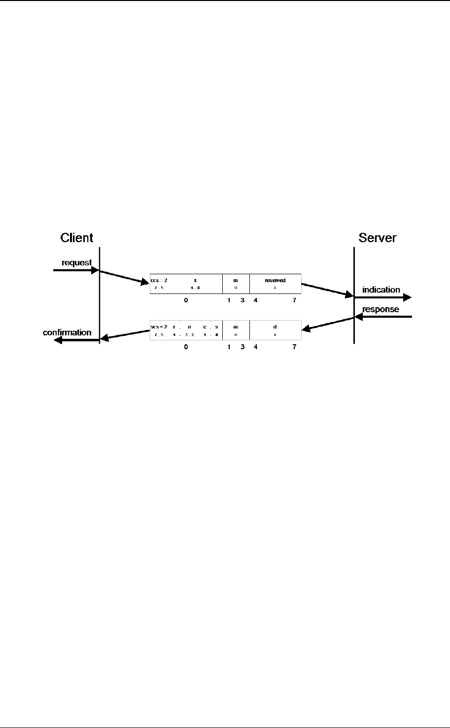
CANopen application layer and communication profile
© CiA 2011 – All rights reserved 51
This protocol (specified in Figure 23) shall be used to implement the SDO upload service. SDOs are
uploaded as a sequence of zero or more SDO upload segment services preceded by an SDO upload
initiate service. The sequence is terminated by:
• An SDO upload initiate response/confirm with the e-bit set to 1, indicating the successful
completion of an expedited upload sequence.
• An SDO upload segment response/confirm with the c-bit set to 1, indicating the successful
completion of a normal upload sequence.
• An SDO abort transfer request/indication, indicating the unsuccessful completion of the upload
sequence.
• A new SDO upload initiate request/indication, indicating the unsuccessful completion of the upload
sequence and the start of a new sequence.
If in the upload of two consecutive segments the toggle bit does not alter, the content of the last
segment shall be ignored. If such an error is reported to the application, the application may decide to
abort the upload.
7.2.4.3.6 Protocol SDO upload initiate
The protocol as defined in Figure 24 shall be used to implement the SDO upload initiate service.
• ccs: client command specifier
2: initiate upload request
• scs: server command specifier
2: initiate upload response
• n: Only valid if e = 1 and s = 1, otherwise 0. If valid it indicates the number of bytes in d that do not
contain data. Bytes [8-n, 7] do not contain segment data.
• e: transfer type
0: normal transfer
1: expedited transfer
• s: size indicator
0: data set size is not indicated
1: data set size is indicated
• m: multiplexer. It represents the index/sub-index of the data to be transfer by the SDO.
• d: data
e = 0, s = 0: d is reserved for further use.
e = 0, s = 1: d contains the number of bytes to be uploaded.
Byte 4 contains the lsb and byte 7 contains the msb.
e = 1, s = 1: d contains the data of length 4-n to be uploaded,
the encoding depends on the type of the data referenced by index and sub-
index
e = 1, s = 0: d contains unspecified number of bytes to be uploaded.
• X: not used, always 0
• reserved: reserved for further use , always 0
Figure 24: Protocol SDO upload initiate
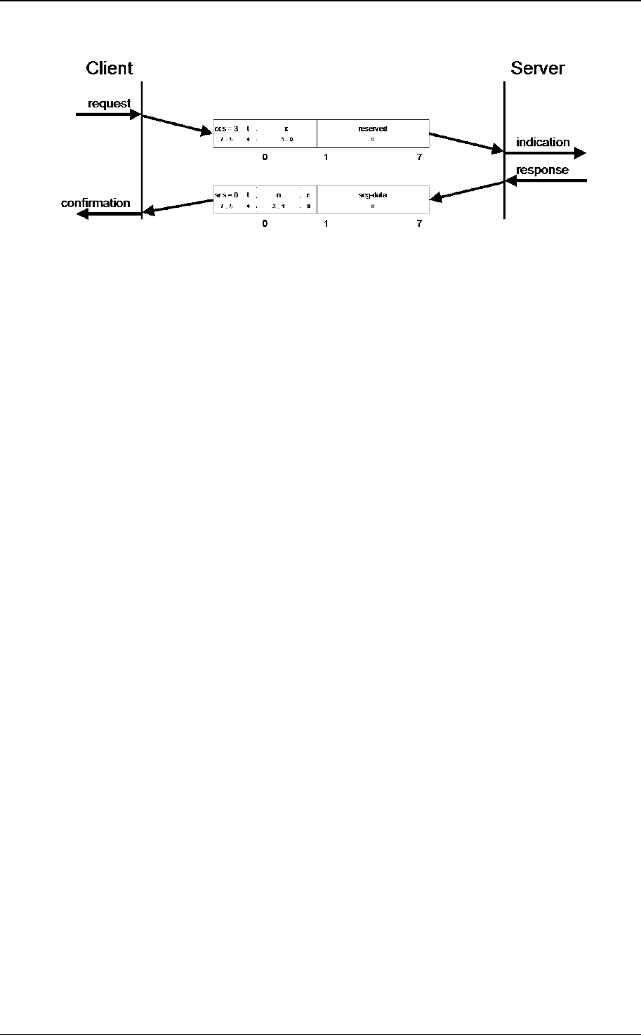
CANopen application layer and communication profile
52 © CiA 2011 – All rights reserved
7.2.4.3.7 Protocol SDO upload segment
The protocol as defined in Figure 25 shall be used to implement the SDO upload segment service.
• ccs: client command specifier
3: upload segment request
• scs: server command specifier
0: upload segment response
• t: toggle bit. This bit shall alternate for each subsequent segment that is uploaded. The first
segment shall have the toggle-bit set to 0. The toggle bit shall be equal for the request and the
response message.
• c: indicates whether there are still more segments to be uploaded.
0: more segments to be uploaded
1: no more segments to be uploaded
• seg-data: at most 7 bytes of segment data to be uploaded. The encoding depends on the type of
the data referenced by index and sub-index
• n: indicates the number of bytes in seg-data that do not contain segment data. Bytes [8-n, 7] do
not contain segment data. If n = 0 bytes 1 to 7 shall contain segment data.
NOTE: If the size in the initiation is indicated this applies to the overall data transferred.
• X: not used, always 0
• reserved: reserved for further use, always 0
Figure 25: Protocol SDO segment upload

CANopen application layer and communication profile
© CiA 2011 – All rights reserved 53
7.2.4.3.8 Protocol SDO block download
Figure 26: Protocol SDO block download
This protocol (specified in Figure 26) shall be used to implement an SDO block download service.
SDOs are downloaded as a sequence of SDO block download sub-block services preceded by an
SDO block download initiate service. The SDO block download sub-block sequence is terminated by:
• A downloaded segment within a block with the c-bit set to 1, indicating the completion of the
SDO block download sequence.
• An SDO abort transfer request/indication, indicating the unsuccessful completion of the
download sequence.
The SDO block download service is terminated with the SDO block download end service. If both the
client and the server have indicated the ability to generate a CRC during the SDO block download
initiate service the server shall generate the CRC on the received data. If this CRC differs from the
CRC generated by the client the server shall indicate this with an SDO abort transfer indication.
7.2.4.3.9 Protocol SDO block download initiate
The protocol as defined in Figure 27 shall be used to implement the SDO block download initiate
service.
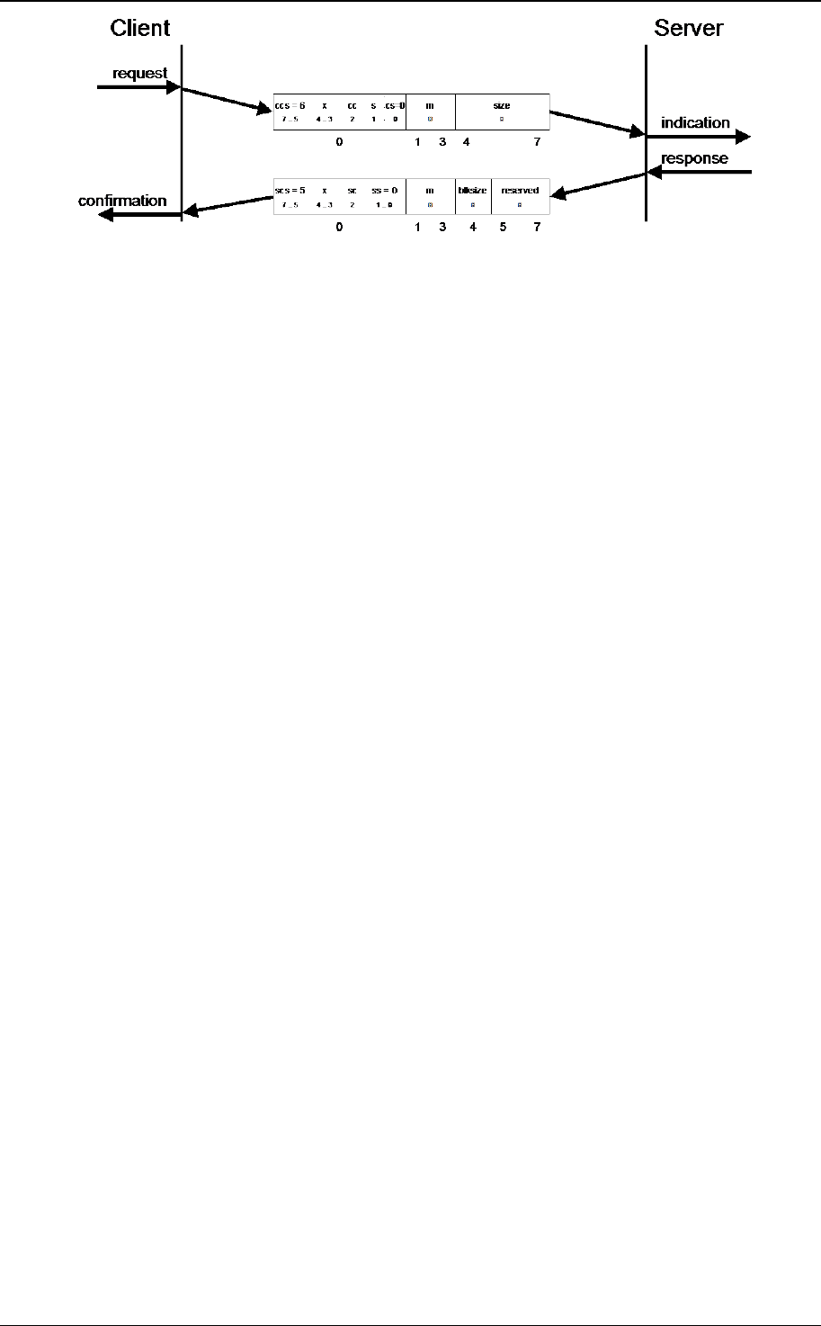
CANopen application layer and communication profile
54 © CiA 2011 – All rights reserved
• ccs: client command specifier
6: block download
• scs: server command specifier
5: block download
• s: size indicator
0: data set size is not indicated
1: data set size is indicated
• cs: client subcommand
0: initiate download request
• ss: server subcommand
0: initiate download response
• cc: client CRC support
cc = 0: Client does not support generating CRC on data
cc = 1: Client supports generating CRC on data
• sc: server CRC support
sc = 0: Server does not support generating CRC on data
sc = 1: Server supports generating CRC on data
• m: multiplexer. It represents the index/sub-index of the data to be transfer by the SDO.
• size: download size in bytes
s = 0: size is reserved for further use, always 0
s = 1: size contains the number of bytes to be downloaded
Byte 4 contains the LSB and byte 7 the MSB
• blksize: Number of segments per block that shall be used by the client for the following block
download with 0 < blksize < 128
• X: not used, always 0
• reserved: reserved for further use, always 0
Figure 27: Protocol SDO block download initiate
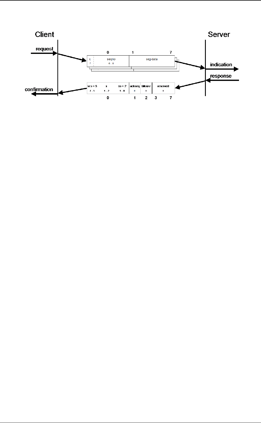
CANopen application layer and communication profile
© CiA 2011 – All rights reserved 55
7.2.4.3.10 Protocol SDO block download sub-block
The protocol as defined in Figure 28 shall be used to implement the SDO block download sub-block
service.
scs: server command specifier
5: block download
ss: server subcommand
2: block download response
• c: indicates whether there are still more segments to be downloaded
0: more segments to be downloaded
1: no more segments to be downloaded, enter SDO block download end phase
seqno: sequence number of segment 0 < seqno < 128.
seg-data: at most 7 bytes of segment data to be downloaded.
ackseq: sequence number of last segment that was received successfully during the last block
download. If ackseq is set to 0 the server indicates the client that the segment with the sequence
number 1 was not received correctly and all segments shall be retransmitted by the client.
• blksize: Number of segments per block that shall be used by the client for the following block
download with 0 < blksize < 128.
• X: not used, always 0
• reserved: reserved for further use, always 0
Figure 28: Protocol SDO block download sub-block

CANopen application layer and communication profile
56 © CiA 2011 – All rights reserved
7.2.4.3.11 Protocol SDO block download end
The protocol as defined in Figure 29 shall be used to implement the SDO block download end service.
ccs: client command specifier
6: block download
scs: server command specifier
5: block download
cs: client subcommand
1: end block download request
ss: server subcommand
1: end block download response
n: indicates the number of bytes in the last segment of the last block that do not contain data. Bytes
[8-n, 7] do not contain segment data.
crc: 16 bit cyclic redundancy checksum (CRC) for the data set. The algorithm for generating the CRC
is described in sub-clause 7.2.4.3.16. CRC is only valid if in SDO block download initiate cc and sc are
set to 1 otherwise CRC shall be set to 0.
X: not used, always 0
reserved: reserved for further use, always 0
Figure 29: Protocol SDO block download end
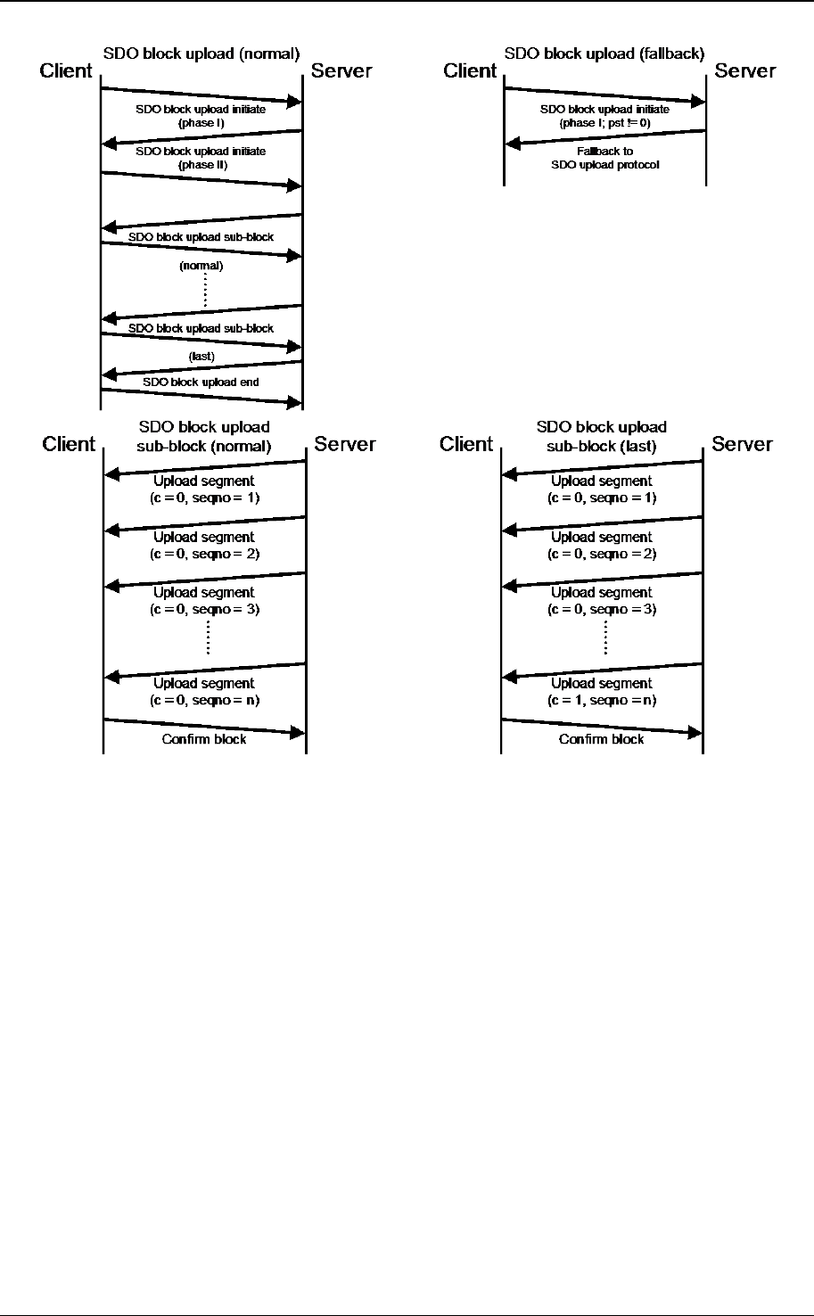
CANopen application layer and communication profile
© CiA 2011 – All rights reserved 57
7.2.4.3.12 Protocol SDO block upload
Figure 30: Protocol SDO block upload
This protocol (specified in Figure 30) shall be used to implement an SDO block upload service which
starts with the SDO block upload initiate service. The client may indicate a threshold value to the
server which is the minimum value in bytes to increase transfer performance using the SDO block
upload protocol instead of the SDO upload protocol. If the data set size is less or equal this value the
server may continue with the normal or expedited transfer of the SDO block upload protocol.
Otherwise SDOs are uploaded as a sequence of SDO block upload sub-block services. The SDO
block upload sub-block sequence is terminated by:
• An uploaded segment within a block with the c-bit set to 1, indicating the completion of the SDO
block upload sub-block sequence.
• AN SDO abort transfer request/indication is indicating the unsuccessful completion of the uploaded
sequence.
The SDO block upload service is terminated with the SDO block upload end service. If both the client
and the server have indicated the ability to generate a CRC during the SDO block upload initiate
service the client shall generate the CRC on the received data. If this CRC differs from the CRC
generated by the server the client shall indicate this with an SDO abort transfer indication.

CANopen application layer and communication profile
58 © CiA 2011 – All rights reserved
7.2.4.3.13 Protocol SDO block upload initiate
The protocol as defined in Figure 31 shall be used to implement the SDO block upload initiate service.
If the value of the protocol switch threshold parameter indicated by the client in the first request is less
or equal the data set size to be uploaded the server may continue with the protocol SDO upload as
described in sub-clause 7.2.4.3.5.
• ccs: client command specifier
5: block upload
• scs: server command specifier
6: block upload
• cs: client subcommand
0: initiate upload request
3: start upload
• ss: server subcommand
0: initiate upload response
• m: multiplexer. It represents the index/sub-index of the data to be transfer by the SDO.
• cc: client CRC support
cc = 0: Client does not support generating CRC on data
cc = 1: Client supports generating CRC on data
• sc: server CRC support
sc = 0: Server does not support generating CRC on data
sc = 1: Server supports generating CRC on data
• pst: protocol switch threshold in bytes to change the SDO transfer protocol
pst = 0: Change of transfer protocol not allowed.
pst > 0: If the size of the data in bytes is less or equal pst the server may switch to the SDO
upload protocol by transmitting the server response of the protocol SDO upload as
described in sub-clause 7.2.4.3.5.
• s: size indicator
0: data set size is not indicated
1: data set size is indicated
size: upload size in bytes
s = 0: size is reserved for further use, always 0
s = 1: size contains the number of bytes to be downloaded
Byte 4 contains the lsb and byte 7 the msb
• blksize: Number of segments per block with 0 < blksize < 128.
• X: not used, always 0
• reserved: reserved for further use, always 0
Figure 31: Protocol SDO block upload initiate
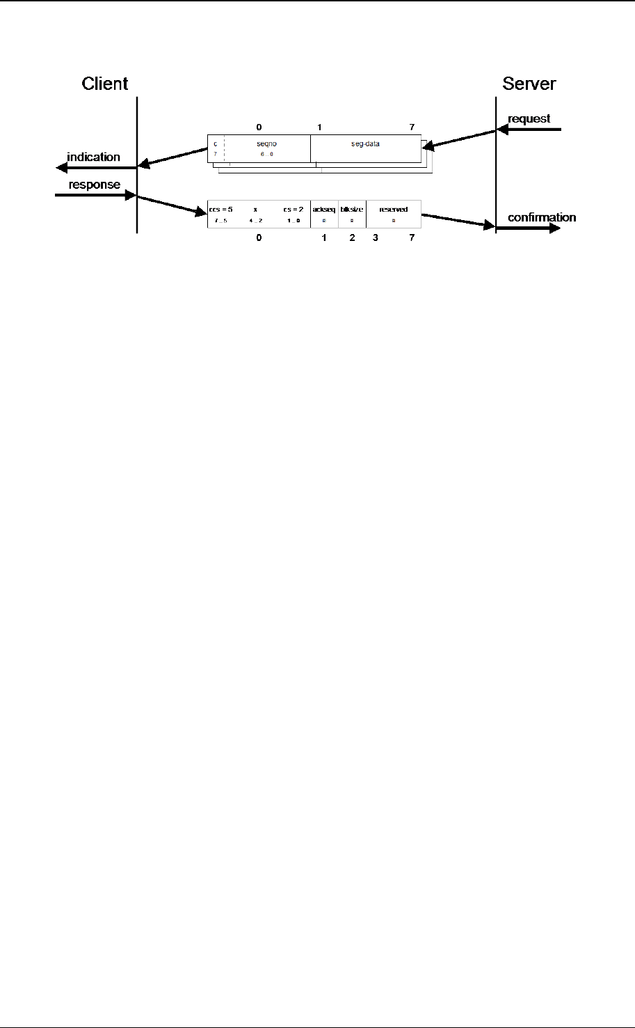
CANopen application layer and communication profile
© CiA 2011 – All rights reserved 59
7.2.4.3.14 Protocol SDO block upload sub-block
The protocol as defined in Figure 32 shall be used to implement the SDO block upload sub-block
service.
• ccs: client command specifier
5: block upload
cs: client subcommand
2: block upload response
• c: indicates whether there are still more segments to be downloaded
0: more segments to be uploaded
1: no more segments to be uploaded, enter ‘End block upload’ phase
seqno: sequence number of segment 0 < seqno < 128.
• seg-data: at most 7 bytes of segment data to be uploaded.
• ackseq: sequence number of last segment that was received successfully during the last block
upload. If ackseq is set to 0 the client indicates the server that the segment with the sequence
number 1 was not received correctly and all segments shall be retransmitted by the server.
• blksize: Number of segments per block that shall be used by server for the following block upload
with 0 < blksize < 128.
• X: not used, always 0
• reserved: reserved for further use, always 0
Figure 32: Protocol SDO block upload sub-block
7.2.4.3.15 Protocol SDO block upload end
The protocol as defined in Figure 33 shall be used to implement the SDO block upload end service.

CANopen application layer and communication profile
60 © CiA 2011 – All rights reserved
ccs: client command specifier
5: block upload
• scs: server command specifier
6: block upload
• cs: client subcommand
1: end block upload request
• ss: server subcommand
1: end block upload response
• n: indicates the number of bytes in the last segment of the last block that do not contain data.
Bytes [8-n, 7] do not contain segment data.
crc: 16 bit cyclic redundancy checksum (CRC) of the data set. The algorithm for generating the CRC
is described in clause 7.2.4.3.16. CRC is only valid if in SDO block upload initiate cc and sc are set to
1 otherwise crc shall be set to 0.
• X: not used, always 0
• reserved: reserved for further use, always 0
Figure 33: Protocol SDO block upload end
7.2.4.3.16 CRC calculation algorithm to verify SDO block transfer
To verify the correctness of an SDO block upload and SDO block download client and server
calculating a CRC that is exchanged and verified during SDO block download end and SDO block
upload end protocol. The CRC shall have the following parameters:
— CRC polynomial: x
16
+ x
12
+ x
5
+ 1
— CRC width: 16 bit
— initial value: 0000
h
— CRC check (result for CRC of 123456789): 31C3
h

CANopen application layer and communication profile
© CiA 2011 – All rights reserved 61
7.2.4.3.17 Protocol SDO abort transfer
The protocol as defined in Figure 34 shall be used to implement the SDO abort transfer service.
• cs: command specifier
4: abort transfer request
• X: not used, always 0
• m: multiplexer. It represents index and sub-index of the SDO.
• d: contains a 4 byte abort code about the reason for the abort.
Figure 34: Protocol SDO abort transfer
The abort code as defined in Table 22 is encoded as UNSIGNED32 value.
Table 22: SDO abort codes
Abort code Description
0503 0000
h
Toggle bit not alternated.
0504 0000
h
SDO protocol timed out.
0504 0001
h
Client/server command specifier not valid or unknown.
0504 0002
h
Invalid block size (block mode only).
0504 0003
h
Invalid sequence number (block mode only).
0504 0004
h
CRC error (block mode only).
0504 0005
h
Out of memory.
0601 0000
h
Unsupported access to an object.
0601 0001
h
Attempt to read a write only object.
0601 0002
h
Attempt to write a read only object.
0602 0000
h
Object does not exist in the object dictionary.
0604 0041
h
Object cannot be mapped to the PDO.
0604 0042
h
The number and length of the objects to be mapped would exceed PDO length.
0604 0043
h
General parameter incompatibility reason.
0604 0047
h
General internal incompatibility in the device.
0606 0000
h
Access failed due to an hardware error.
0607 0010
h
Data type does not match, length of service parameter does not match
0607 0012
h
Data type does not match, length of service parameter too high
0607 0013
h
Data type does not match, length of service parameter too low
0609 0011
h
Sub-index does not exist.

CANopen application layer and communication profile
62 © CiA 2011 – All rights reserved
Abort code Description
0609 0030
h
Invalid value for parameter (download only).
0609 0031
h
Value of parameter written too high (download only).
0609 0032
h
Value of parameter written too low (download only).
0609 0036
h
Maximum value is less than minimum value.
060A 0023
h
Resource not available: SDO connection
0800 0000
h
General error
0800 0020
h
Data cannot be transferred or stored to the application.
0800 0021
h
Data cannot be transferred or stored to the application because of local control.
0800 0022
h
Data cannot be transferred or stored to the application because of the present
device state.
0800 0023
h
Object dictionary dynamic generation fails or no object dictionary is present (e.g.
object dictionary is generated from file and generation fails because of an file error).
0800 0024
h
No data available
The abort codes not listed shall be reserved.
7.2.5 Synchronization object (SYNC)
7.2.5.1 General
The SYNC producer broadcasts the synchronization object periodically. This SYNC provides the basic
network synchronization mechanism. The time period between the SYNCs is specified by the standard
parameter communication cycle period (see sub-clause 7.5.2.6), which may be written by a
configuration tool to the CANopen devices during the boot-up process. There may be a time jitter in
transmission by the SYNC producer corresponding approximately to the latency due to some other
message being transmitted just before the SYNC. The SYNC consumer may use the communication
cycle period manufacturer specific.
The optional parameter counter is used to define an explicit relationship between the current SYNC
cycle and PDO transmission (see PDO communication parameter SYNC start value at sub-clause
7.5.2.37).
In order to guarantee timely access to the network the SYNC is given a very high priority CAN-ID (see
sub-clause 7.5.2.5). CANopen devices that operate synchronously may use the SYNC object to
synchronize their own timing with that of the synchronization object producer. The details of this
synchronization are application-specific and do not fall within the scope of this specification.
7.2.5.2 SYNC services
7.2.5.2.1 General
The SYNC transmission follows the producer/consumer push model as described in clause 4.4.4. The
service is unconfirmed.
Attributes:
- user type: one of the values {consumer, producer}
- data type: UNSIGNED8
7.2.5.2.2 Service SYNC write
For the SYNC write service the push model is valid. There are zero or more consumers for SYNC. The
SYNC has exactly one producer. The parameter for this service is defined in Table 23.
Through this service the producer of the SYNC sends a trigger event to the consumer(s).

CANopen application layer and communication profile
© CiA 2011 – All rights reserved 63
Table 23: Service SYNC write
Parameter Request / Indication
Argument
counter
Mandatory
optional
The service is unconfirmed. The optional parameter counter shall be incremented by 1 with every
transmission. The maximum value shall be the current value as defined in the synchronous counter
overflow value (see sub-clause 7.5.2.22). In case the maximum value is reached the counter shall be
set to 1 with the next transmission. The initial value of the counter after the NMT service boot-up shall
be 1. The value of the counter shall be reset to 1 if the CANopen device transits from the NMT state
stopped into the NMT state pre-operational or into the NMT state operational.
7.2.5.3 SYNC protocol
7.2.5.3.1 Protocol SYNC write
This protocol as defined in Figure 35 shall be used to implement the service SYNC write.
• Counter: 1 byte of a counter
Figure 35: Protocol SYNC write
7.2.6 Time stamp object (TIME)
7.2.6.1 General
The TIME producer broadcasts the time stamp object. This TIME provides the simple network clock.
There may be a time jitter in transmission by the TIME producer corresponding approximately to the
latency due to some other message being transmitted just before the TIME.
In order to guarantee timely access to the network the TIME is given a very high priority CAN-ID (see
sub-clause 7.5.2.15). CANopen devices that operate a local clock may use the TIME object to adjust
their own time base to that of the time stamp object producer. The details of this mechanism are
implementation specific and do not fall within the scope of this specification.
7.2.6.2 TIME services
7.2.6.2.1 General
The time stamp object transmission follows the producer/consumer as described in sub-clause 4.4.4.
The service is unconfirmed.
Attributes:
- user type: one of the values {consumer, producer}
- data type: TIME_OF_DAY
7.2.6.2.2 Service TIME write
For the TIME write service the push model is valid. There are zero or more consumers of a TIME. A
TIME has exactly one producer. The parameter for this service is defined in Table 24.
Through this service the producer of a TIME sends the current time to the consumer(s).
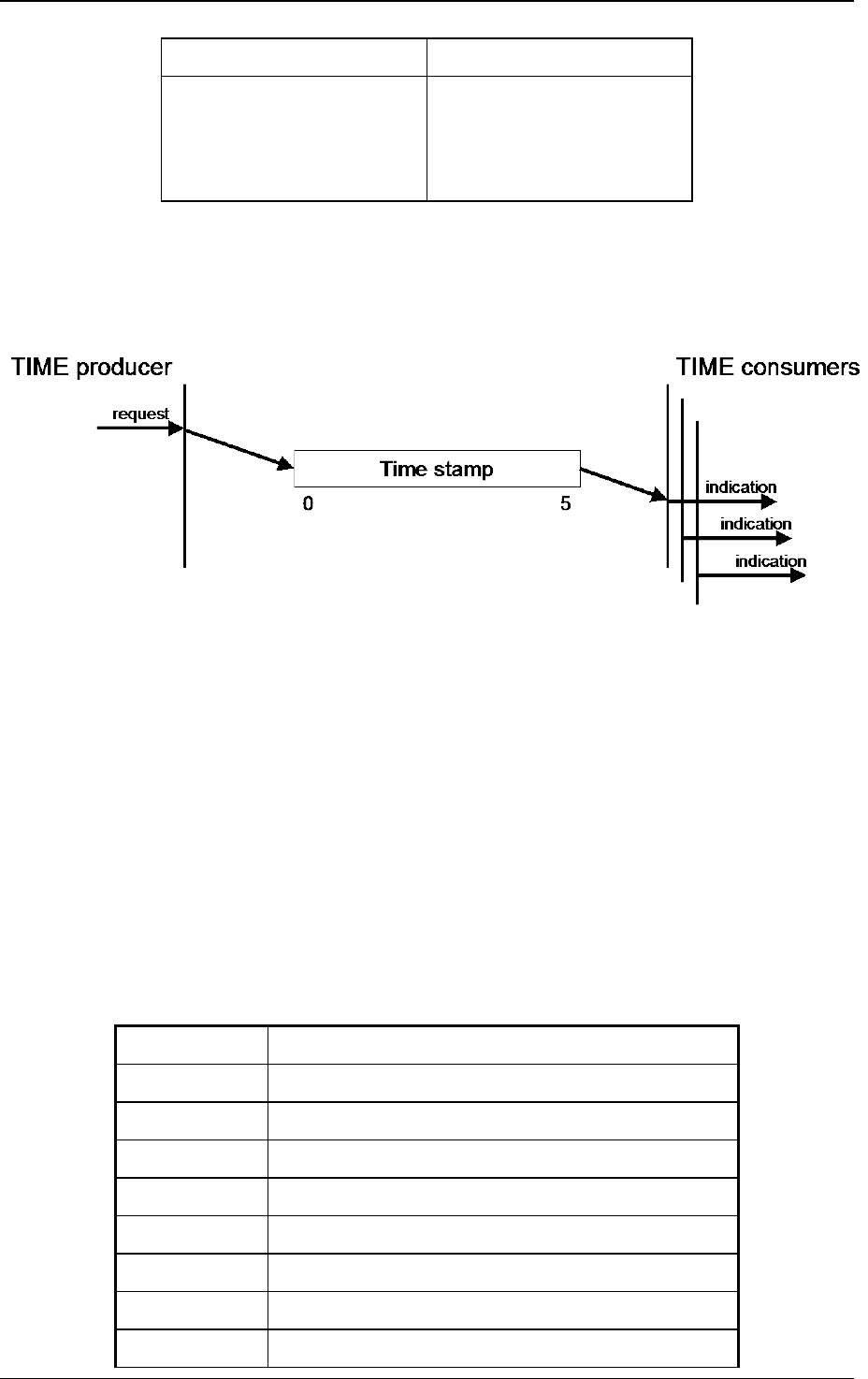
CANopen application layer and communication profile
64 © CiA 2011 – All rights reserved
Table 24: Service TIME write
Parameter Request / Indication
Argument
Data
Mandatory
mandatory
The service is unconfirmed.
7.2.6.3 TIME protocol
7.2.6.3.1 Protocol TIME write
This protocol as defined in Figure 36 shall be used to implement the service TIME write.
• Time stamp: 6 bytes of the time stamp object
Figure 36: Protocol TIME write
7.2.7 Emergency object (EMCY)
7.2.7.1 Emergency object usage
Emergency objects are triggered by the occurrence of a CANopen device internal error situation and
are transmitted from an emergency producer on the CANopen device. Emergency objects are suitable
for interrupt type error alerts. An emergency object is transmitted only once per 'error event'. No further
emergency objects shall be transmitted as long as no new errors occur on a CANopen device.
Zero or more emergency consumers may receive the emergency object. The reaction on the
emergency consumer(s) is not specified and does not fall in the scope of this specification.
By means of this specification emergency error code classes (Table 25), emergency error codes
(Table 26) and the error register (see sub-clause 7.5.2.2) are specified. Application-specific additional
information in the lower byte of the emergency error code and the emergency condition do not fall into
the scope of this specification. Additional error codes are defined by other profile specifications.
Table 25: Emergency error code classes
Error code Description
00xx
h
Error reset or no error
10xx
h
Generic error
20xx
h
Current
21xx
h
Current, CANopen device input side
22xx
h
Current inside the CANopen device
23xx
h
Current, CANopen device output side
30xx
h
Voltage
31xx
h
Mains voltage

CANopen application layer and communication profile
© CiA 2011 – All rights reserved 65
Error code Description
32xx
h
Voltage inside the CANopen device
33xx
h
Output voltage
40xx
h
Temperature
41xx
h
Ambient temperature
42xx
h
CANopen device temperature
50xx
h
CANopen device hardware
60xx
h
CANopen device software
61xx
h
Internal software
62xx
h
User software
63xx
h
Data set
70xx
h
Additional modules
80xx
h
Monitoring
81xx
h
Communication
82xx
h
Protocol error
90xx
h
External error
F0xx
h
Additional functions
FFxx
h
CANopen device specific
Table 26: Emergency error codes
Error code Description
0000
h
Error reset or no error
1000
h
Generic error
2000
h
Current – generic error
2100
h
Current, CANopen device input side – generic
2200
h
Current inside the CANopen device – generic
2300
h
Current, CANopen device output side – generic
3000
h
Voltage – generic error
3100
h
Mains voltage – generic
3200
h
Voltage inside the CANopen device – generic
3300
h
Output voltage – generic
4000
h
Temperature – generic error
4100
h
Ambient temperature – generic
4200
h
Device temperature – generic
5000
h
CANopen device hardware – generic error
6000
h
CANopen device software – generic error

CANopen application layer and communication profile
66 © CiA 2011 – All rights reserved
Error code Description
6100
h
Internal software – generic
6200
h
User software – generic
6300
h
Data set – generic
7000
h
Additional modules – generic error
8000
h
Monitoring – generic error
8100
h
Communication – generic
8110
h
CAN overrun (objects lost)
8120
h
CAN in error passive mode
8130
h
Life guard error or heartbeat error
8140
h
recovered from bus off
8150
h
CAN-ID collision
8200
h
Protocol error - generic
8210
h
PDO not processed due to length error
8220
h
PDO length exceeded
8230
h
DAM MPDO not processed, destination
object not available
8240
h
Unexpected SYNC data length
8250
h
RPDO timeout
9000
h
External error – generic error
F000
h
Additional functions – generic error
FF00
h
Device specific – generic error
The emergency object is optional. If a CANopen device supports the emergency object, it shall
support at least the two error codes 0000
h
and 1000
h
. All other error codes are optional.
A CANopen device shall be in one of two emergency states (Figure 37). Dependent on the transitions
emergency objects shall be transmitted. Links between the error state machine and the NMT state
machine are defined by object 1029
h
(see sub-clause 7.5.2.32).
0. After initialization the CANopen device enters the error free state if no error is detected. No
error message is sent.
1. The CANopen device detects an internal error indicated in the first three bytes of the
emergency message (error code and error register). The CANopen device enters the error
state. An emergency object with the appropriate error code and error register is transmitted.
The error code is filled in at the location of object 1003
h
(pre-defined error field).
2. One, but not all error reasons are gone. An emergency message containing error code 0000
h
(Error reset) may be transmitted together with the remaining errors in the error register and in
the manufacturer-specific error field.
3. A new error occurs on the CANopen device. The CANopen device remains in error state and
transmits an emergency object with the appropriate error code. The new error code is filled in
at the top of the array of error codes (1003
h
). It shall be guaranteed that the error codes are
sorted in a timely manner (oldest error - highest sub-index, see object 1003
h
).
4. All errors are repaired. The CANopen device enters the error free state and transmits an
emergency object with the error code ‘reset error / no error'.
5. Reset or power-off.

CANopen application layer and communication profile
© CiA 2011 – All rights reserved 67
Figure 37: Emergency state transition diagram
7.2.7.2 Emergency object services
7.2.7.2.1 General
The emergency object transmission follows the producer/consumer as described in sub-clause 4.4.4.
The service is unconfirmed.
The following object attributes are specified for emergency objects:
- user type: one of the values {consumer, producer}
- data type: STRUCTURE OF
UNSIGNED16 emergency_error_code,
UNSIGNED8 error_register,
ARRAY (5) of UNSIGNED8 manufacturer_specific_error_field
- inhibit-time: n*100 µs, n > 0
7.2.7.2.2 Service EMCY write
For the EMCY write service the push model is valid. There are zero or more consumers for EMCY.
EMCY has exactly one producer. The parameter for this service is defined in Table 27.
Through this service the producer of EMCY sends the current emergency data to the consumer(s).
Table 27: Service EMCY write
Parameter Request / Indication
Argument
Data
Mandatory
mandatory
The service is unconfirmed.
7.2.7.3 Emergency object protocol
7.2.7.3.1 Protocol EMCY write
This protocol as defined in Figure 38 shall be used to implement the service EMCY write.
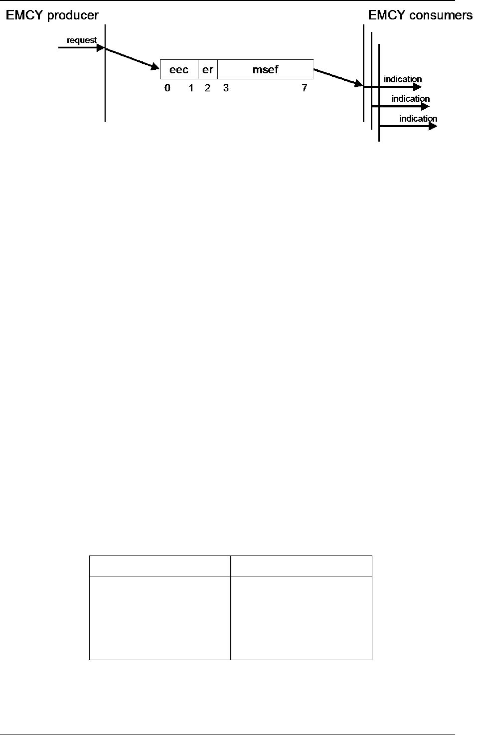
CANopen application layer and communication profile
68 © CiA 2011 – All rights reserved
• eec: Emergency error code (see Table 26)
• er: Error register (see object 1001
h
)
• msef: Manufacturer-specific error code
Figure 38: Protocol EMCY write
A RTR is not allowed to inquire for an emergency transmission. A received RTR shall not be
answered.
7.2.8 Network management
7.2.8.1 General
The network management (NMT) is CANopen device oriented and follows a master-slave structure.
NMT objects are used for executing NMT services. Through NMT services, CANopen devices are
initialized, started, monitored, reset or stopped. All CANopen devices are regarded as NMT slaves. An
NMT slave is uniquely identified in the network by its node-ID, a value in the range of [1..127].
NMT requires that one CANopen device in the network fulfils the function of the NMT master.
7.2.8.2 NMT services
7.2.8.2.1 Node control services
7.2.8.2.1.1 General
Through node control services, the NMT master controls the NMT state of the NMT slaves. The NMT
state attribute is one of the values {Stopped, Pre-operational, Operational, Initialisation}. The node
control services may be performed with a certain CANopen device or with all CANopen devices
simultaneously. The NMT master controls its own NMT state machine via local services, which are
implementation dependent. The node control services may be initiated by the local application.
7.2.8.2.1.2 Service start remote node
The NMT master uses the NMT service start remote node to change the NMT state of the selected
NMT slaves. The new NMT state shall be the NMT state operational. The parameters for this service
are defined in Table 28.
Table 28: Service start remote node
Parameter Indication/Request
Argument
Node-ID
All
Mandatory
selection
selection
The service is unconfirmed and mandatory.

CANopen application layer and communication profile
© CiA 2011 – All rights reserved 69
7.2.8.2.1.3 Service stop remote node
The NMT master uses the NMT service stop remote node to change the NMT state of the selected
NMT slaves. The new NMT state shall be the NMT state stopped. The parameters for this service are
defined in Table 29.
Table 29: Service stop remote node
Parameter Request/Indication
Argument
Node-ID
All
Mandatory
selection
selection
The service is unconfirmed and mandatory.
7.2.8.2.1.4 Service enter pre-operational
The NMT master uses the NMT service enter pre-operational to change the NMT state of the selected
NMT slaves. The new NMT state shall be the NMT state pre-operational. The parameters for this
service are defined in Table 30.
Table 30: Service enter pre-operational
Parameter Request/Indication
Argument
Node-ID
All
Mandatory
selection
selection
The service is unconfirmed and mandatory.
7.2.8.2.1.5 Service reset node
The NMT master uses the NMT service reset node to change the NMT state of the selected NMT
slaves. The new NMT state shall be the NMT sub-state reset application. The parameters for this
service are defined in Table 31.
Table 31: Service reset node
Parameter Request/Indication
Argument
Node-ID
All
Mandatory
selection
selection
The service is unconfirmed and mandatory.
7.2.8.2.1.6 Service reset communication
The NMT master uses the NMT service reset communication to change the NMT state of the selected
NMT slaves. The new NMT state shall be the NMT sub-state reset communication. The parameters for
this service are defined in Table 32.

CANopen application layer and communication profile
70 © CiA 2011 – All rights reserved
Table 32: Service reset communication
Parameter Request/Indication
Argument
Node-ID
All
Mandatory
selection
selection
The service is unconfirmed and mandatory.
7.2.8.2.2 Error control services
The error control services are used to detect failures within a CAN-based network.
Local errors in a CANopen device may e.g. lead to a reset or change of state. The definition of these
local errors does not fall into the scope of this specification.
Error control services are achieved principally through periodically transmitting of messages by a
CANopen device. There exist two possibilities to perform error control.
The guarding is achieved by transmitting guarding requests (node guarding protocol) by the NMT
master. If a NMT slave has not responded within a defined span of time (node life time) or if the NMT
slave’s communication status has changed, the NMT master informs its NMT master application about
that event.
If life guarding (the NMT slave guarding the NMT master) is supported, the NMT slave uses the guard
time and life time factor from its object dictionary to determine its node lifetime. If the NMT slave is not
guarded within its lifetime, the NMT slave informs its local application about that event. If guard time
and life time factor are 0 (default values), the NMT slave does not guard the NMT master.
Guarding starts for the NMT slave when the first RTR for its guarding CAN-ID is received. This may be
during the boot-up phase or later.
The heartbeat mechanism for a CANopen device is established by cyclically transmitting the heartbeat
message by the heartbeat producer. One or more CANopen devices in the network are aware of this
heartbeat message. If the heartbeat cycle fails for the heartbeat producer the local application on the
heartbeat consumer will be informed about that event.
The implementation of either guarding or heartbeat is mandatory.
NOTE: Even though both Heartbeat and Guarding are disabled by default, it is recommended to use
error control mechanisms.
7.2.8.2.2.1 Service node guarding event
Through this service, the NMT service provider on the NMT master indicates that a remote error is
occurred or is resolved for the remote CANopen device identified by node-ID. The parameters for this
service are defined in Table 33.
The event resolved is indicated
• when after the event occurred with the reason state change the expected state is received, or
• when after the event occurred with the reason time out one of the subsequent remote indications
is confirmed.

CANopen application layer and communication profile
© CiA 2011 – All rights reserved 71
Table 33: Service node guarding event
Parameter Indication
Argument
Node-ID
State
Occurred
Resolved
Reason
Time out
State change
Mandatory
mandatory
mandatory
selection
selection
optional
selection
selection
The service is provider initiated and optional.
7.2.8.2.2.2 Service life guarding event
Through this service, the NMT service provider on an NMT slave indicates that a remote error
occurred or has been resolved. The parameters for this service are defined in Table 34.
The event resolved is indicated when after the event occurred a subsequent remote request is
received.
Table 34: Service life guarding event
Parameter Indication
Argument
State
Occurred
Resolved
Mandatory
mandatory
selection
selection
The service is provider initiated and optional.
7.2.8.2.2.3 Service heartbeat event
Through this service, the heartbeat consumer shall indicate that a heartbeat error occurred or has
been resolved or a NMT state change has occurred for the CANopen device identified by node-ID.
The parameters for this service are defined in Table 35.
The event resolved is indicated when after the event occurred a subsequent remote indication is
received.
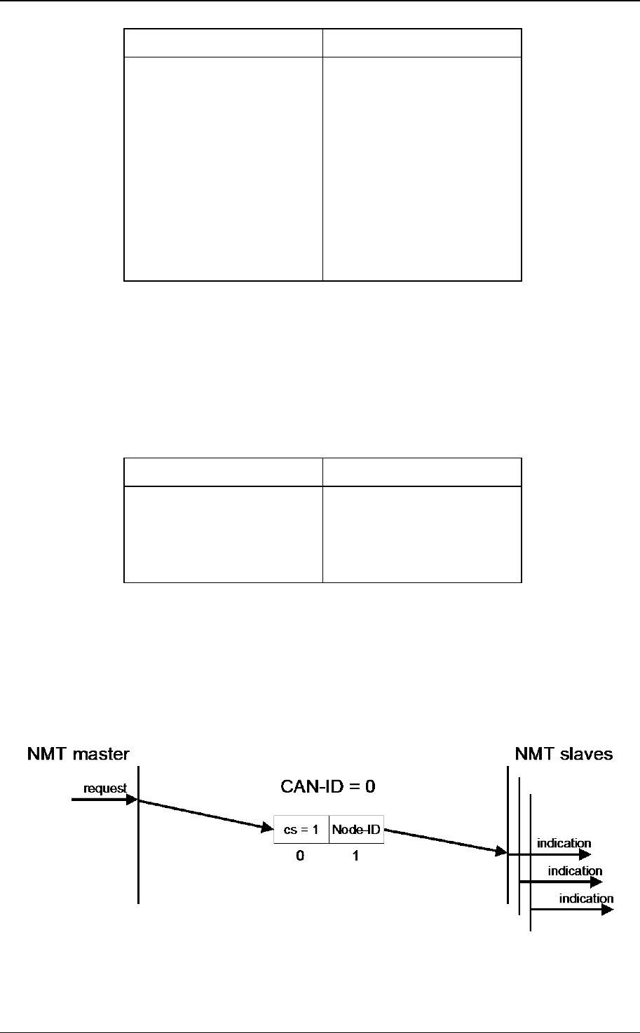
CANopen application layer and communication profile
72 © CiA 2011 – All rights reserved
Table 35: Service heartbeat event
Parameter Indication
Argument
Node-ID
State
Occurred
Resolved
Reason
Time out
State change
Mandatory
mandatory
mandatory
selection
selection
mandatory
selection
selection
The service is consumer initiated and optional.
7.2.8.2.3 Boot-up service
7.2.8.2.3.1 Service boot-up Event
Through this service, the NMT slave indicates that a local state transition occurred from the NMT state
Initialisation to the NMT state Pre-operational. The parameter for this service is defined in Table 36.
Table 36: Service boot-up event
Parameter Indication
Argument
Node-ID
Mandatory
mandatory
The service is provider initiated and mandatory.
7.2.8.3 NMT protocols
7.2.8.3.1 Node control protocols
7.2.8.3.1.1 Protocol start remote node
The protocol as defined in Figure 39 shall be used to implement the NMT service start remote node.
cs: NMT command specifier
1: start
Figure 39: Protocol start remote node

CANopen application layer and communication profile
© CiA 2011 – All rights reserved 73
7.2.8.3.1.2 Protocol stop remote node
The protocol as defined in Figure 40 shall be used to implement the NMT service stop remote node.
cs: NMT command specifier
2: stop
Figure 40: Protocol stop remote node
7.2.8.3.1.3 Protocol enter pre-operational
The protocol as defined in Figure 41 shall be used to implement the NMT service enter pre-
operational.
cs: NMT command specifier
128: enter pre-operational
Figure 41: Protocol enter pre-operational
7.2.8.3.1.4 Protocol reset node
The protocol as defined in Figure 42 shall be used to implement the NMT service reset node.
cs: NMT command specifier
129: reset node
Figure 42: Protocol reset node
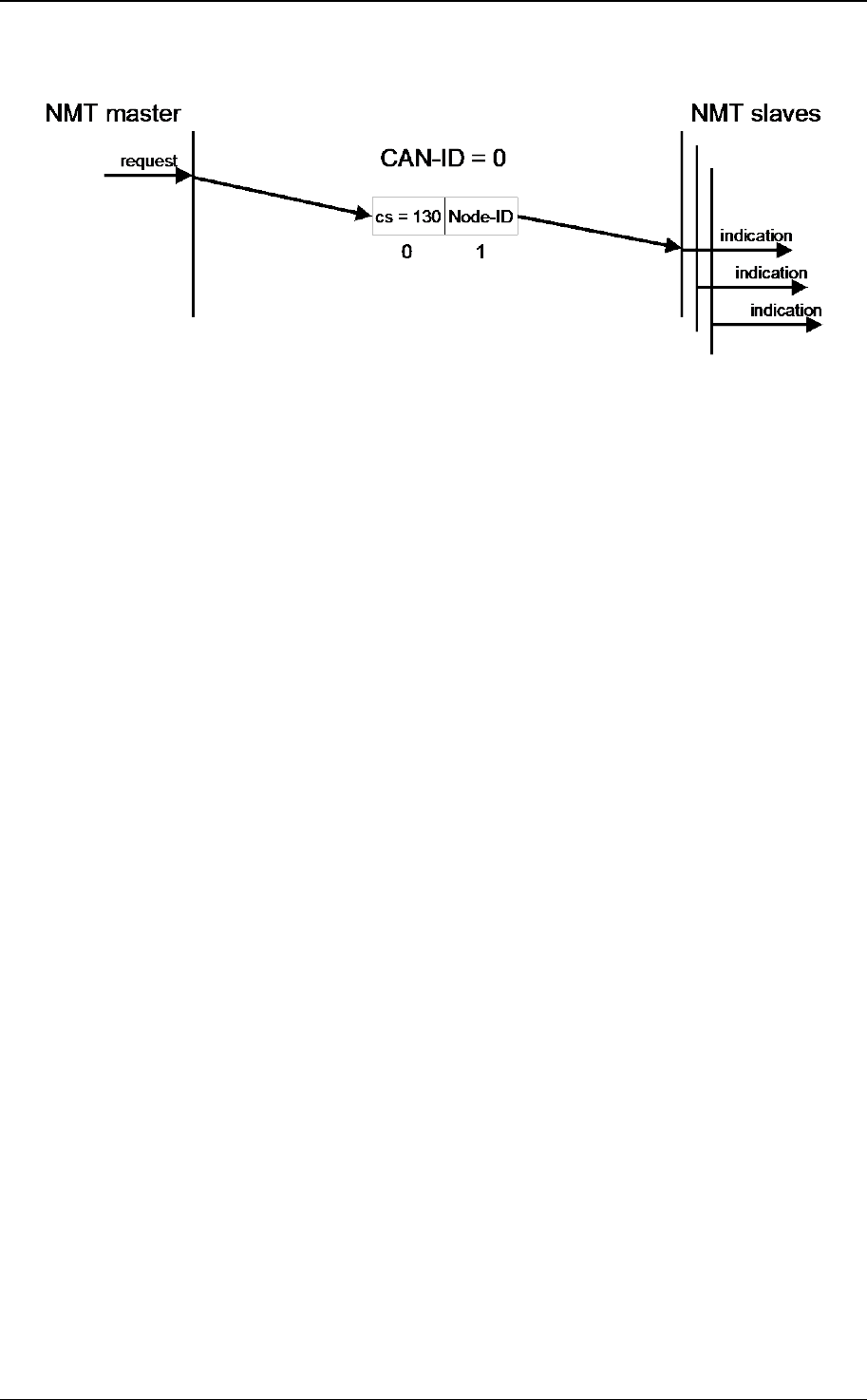
CANopen application layer and communication profile
74 © CiA 2011 – All rights reserved
7.2.8.3.1.5 Protocol reset communication
The protocol as defined in Figure 43 shall be used to implement the NMT service reset
communication.
cs: NMT command specifier
130: reset communication
Figure 43: Protocol reset communication
7.2.8.3.2 Error Control Protocols
7.2.8.3.2.1 Protocol node guarding
The protocol as defined in Figure 44 shall be used to detect remote errors in the network. Each NMT
slave serves one RTR for the node guarding protocol. This protocol implements the provider initiated
error control services.

CANopen application layer and communication profile
© CiA 2011 – All rights reserved 75
s: the state of the NMT slave
4: Stopped
5: Operational
127: Pre-operational
t: toggle bit. The value of this bit shall alternate between two consecutive responses from the NMT
slave. The value of the toggle-bit of the first response after the guarding protocol becomes active
shall be 0. The toggle bit in the guarding protocol shall be reset to 0 when the NMT sub-state reset
communication is passed (no other change of NMT state resets the toggle bit). If a response is
received with the same value of the toggle-bit as in the preceding response then the new
response is handled as if it was not received.
Figure 44: Protocol node guarding
The NMT master polls each NMT slave at regular time intervals. This time-interval is called the guard
time and may be different for each NMT slave. The response of the NMT slave contains the NMT state
of that NMT slave. The node lifetime is given by the guard time multiplied by the lifetime factor. The
node lifetime may be different for each NMT slave. If the NMT slave has not been polled during its
lifetime, a remote node error is indicated through the NMT service life guarding event.
A remote node error is indicated through the NMT service node guarding event if
• The RTR is not confirmed within the node life time
• The reported NMT slave state does not match the expected state
If it has been indicated that a remote error has occurred and the errors in the guarding protocol have
disappeared, it will be indicated that the remote error has been resolved through the NMT service
node guarding event and the NMT service life guarding event.
For the guard time, and the life time factor there are default values specified at the appropriate object
dictionary objects.

CANopen application layer and communication profile
76 © CiA 2011 – All rights reserved
7.2.8.3.2.2 Protocol heartbeat
The heartbeat protocol as defined in Figure 45 defines an error control service without need for RTRs.
A heartbeat producer transmits a heartbeat message cyclically. One or more heartbeat consumer
receives the indication. The relationship between producer and consumer is configurable via the
object dictionary. The heartbeat consumer guards the reception of the heartbeat within the heartbeat
consumer time. If the heartbeat is not received within the heartbeat consumer time a heartbeat event
will be generated.
• r: reserved (always 0)
• s: the state of the heartbeat producer
0: Boot-up
4: Stopped
5: Operational
127: Pre-operational
Figure 45: Protocol heartbeat
If the heartbeat producer time is configured on a CANopen device the heartbeat protocol begins
immediately. If a CANopen device starts with a value for the heartbeat producer time unequal to 0 the
heartbeat protocol starts on the transition from the NMT state Initialisation to the NMT state Pre-
operational. In this case the boot-up message is regarded as first heartbeat message. It is not allowed
to use both error control mechanisms guarding protocol and heartbeat protocol on one NMT slave at
the same time. If the heartbeat producer time is unequal 0 the heartbeat protocol is used.

CANopen application layer and communication profile
© CiA 2011 – All rights reserved 77
7.2.8.3.3 Protocol boot-up
The protocol as defined in Figure 46 shall be used to signal that a NMT slave has entered the NMT
state Pre-operational after the NMT state Initialising. The protocol uses the same CAN-ID as the error
control protocols.
One data byte is transmitted with value 0.
Figure 46: Protocol boot-up
7.3 Network initialization and system boot-up
7.3.1 Simplified NMT startup
An example of a simplified NMT startup is shown in Figure 47. The definition of the process NMT
startup does not fall into the scope of this specification.
Figure 47: NMT startup simple
7.3.2 NMT state machine
7.3.2.1 Overview
In Figure 48 the NMT state diagram of a CANopen device is specified. CANopen devices enter the
NMT state Pre-operational directly after finishing the CANopen devices initialization. During this NMT
state CANopen device parameterization and CAN-ID-allocation via SDO (e.g. using a configuration
tool) is possible. Then the CANopen devices may be switched directly into the NMT state Operational.
The NMT state machine determines the behavior of the communication function unit (see sub-clause
4.3). The coupling of the application state machine to the NMT state machine is CANopen device
dependent and falls into the scope of device profiles and application profiles.
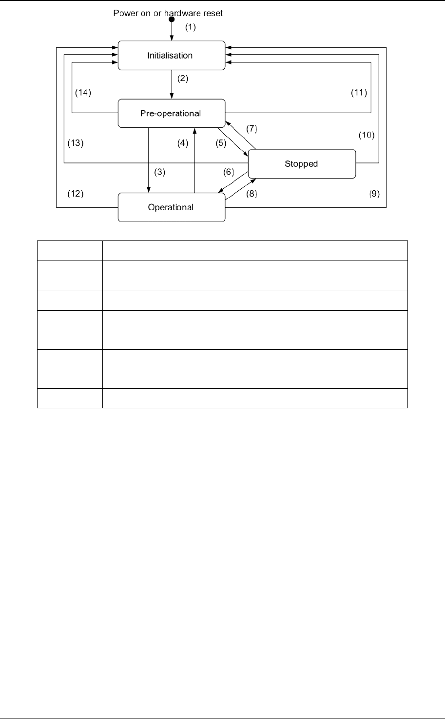
CANopen application layer and communication profile
78 © CiA 2011 – All rights reserved
(1) At Power on the NMT state initialisation is entered autonomously
(2) NMT state Initialisation finished - enter NMT state Pre-operational
automatically
(3) NMT service start remote node indication or by local control
(4),(7) NMT service enter pre-operational indication
(5),(8) NMT service stop remote node indication
(6) NMT service start remote node indication
(9),(10),(11) NMT service reset node indication
(12),(13),(14) NMT service reset communication indication
Figure 48: NMT state diagram of a CANopen device
7.3.2.2 NMT states
7.3.2.2.1 NMT state Initialisation
The NMT state initialisation shall be divided into three NMT sub-states (specified in Figure 49) in order
to enable a complete or partial reset of a CANopen device.
1. Initialising: This is the first NMT sub-state the CANopen device enters after power-on or hardware
reset. After finishing the basic CANopen device initialisation the CANopen device enters
autonomously into the NMT sub-state reset application.
2. Reset application: In this NMT sub-state the parameters of the manufacturer-specific profile area
and of the standardized device profile area are set to their power-on values. After setting of the
power-on values the NMT sub-state reset communication is entered autonomously.
3. Reset communication: In this NMT sub-state the parameters of the communication profile area
are set to their power-on values. After this the NMT state Initialisation is finished and the CANopen
device executes the NMT service boot-up write and enters the NMT state Pre-operational.
Power-on values are the last stored parameters. If storing is not supported or has not been executed
or if the reset was preceded by the command restore defaults (see clause 7.5.2.14), the power-on
values are the default values according to the communication and device profile specifications.

CANopen application layer and communication profile
© CiA 2011 – All rights reserved 79
(1) At power on the NMT state initialisation is entered autonomously
(2) NMT state Initialisation finished - enter NMT state Pre-operational automatically
(12), (13), (14) NMT service reset communication indication
(9), (10), (11) NMT service reset node indication
(15) NMT sub-state Initialization finished – NMT sub-state reset application is entered
autonomously
(16) NMT sub-state reset application is finished – NMT sub-state reset communication
is entered autonomously
Figure 49: Structure of the NMT state Initialization
7.3.2.2.2 NMT state Pre-operational
In the NMT state Pre-operational, communication via SDOs is possible. PDOs do not exist, so PDO
communication is not allowed. Configuration of PDOs, parameters and also the allocation of
application objects (PDO mapping) may be performed by a configuration application.
The CANopen device may be switched into the NMT state Operational directly by sending the NMT
service start remote node or by means of local control.
7.3.2.2.3 NMT state Operational
In the NMT state Operational all communication objects are active. Transitioning to the NMT state
Operational creates all PDOs; the constructor uses the parameters as described in the object
dictionary. Object dictionary access via SDO is possible. Implementation aspects or the application
state machine however may require to limit the access to certain objects whilst being in the NMT state
Operational, e.g. an object may contain the application program which cannot be changed during
execution.
7.3.2.2.4 NMT state Stopped
By switching a CANopen device into the NMT state Stopped it is forced to stop the communication
altogether (except node guarding and heartbeat, if active). Furthermore, this NMT state may be used
to achieve certain application behavior. The definition of this behavior falls into the scope of device
profiles and application profiles.
If there are EMCY messages triggered in this NMT state they are pending. The most recent active
EMCY reason may be transmitted after the CANopen device transits into another NMT state.
NOTE: The error history may be read by accessing the object 1003
h
, if implemented.

CANopen application layer and communication profile
80 © CiA 2011 – All rights reserved
7.3.2.2.5 NMT states and communication object relation
Table 37 specifies the relation between NMT states and communication objects. Services on the listed
communication objects may only be executed if the CANopen devices involved in the communication
are in the appropriate NMT states.
Table 37: NMT states and communication objects
Pre-operational Operational Stopped
PDO X
SDO X X
SYNC X X
TIME X X
EMCY X X
Node control and
error control
X X X
7.3.2.3 NMT state transitions
NMT state transitions are caused by
• reception of an NMT service used for node control services,
• hardware reset, or
• node control services locally initiated by application events, defined by device profiles and
application profiles
7.3.3 Generic pre-defined connection set
In order to reduce configuration effort for simple networks a CAN-ID allocation scheme is defined.
These CAN-IDs shall be available in the NMT state Pre-operational directly after the NMT state
Initialization (if no modifications have been stored). The objects SYNC, TIME, EMCY write and PDO
may be deleted and re-created with new CAN-IDs by means of dynamic distribution. A CANopen
device shall provide the corresponding CAN-IDs only for the supported communication objects.
The CAN-ID-allocation scheme (defined in Table 38 and Table 39) consists of a functional part, which
determines the object priority and a node-ID part, which allows to distinguish between CANopen
devices of the same functionality. This allows a peer-to-peer communication between a single master
CANopen device and up to 127 NMT slave CANopen devices. It also supports the broadcasting of
non-confirmed NMT, SYNC and TIME messages. Broadcasting is indicated by a node-ID of zero.
The generic pre-defined connection set supports one emergency object, one SDO, at maximum
4 RPDOs and 4 TPDOs and the NMT objects.
10 9 8 7 6 5 4 3 2 1 0
CAN-ID
Function code Node-ID
MSB LSB
Figure 50: CAN-ID-allocation scheme for the generic pre-defined connection
set
Table 38 and Table 39 show the supported objects and their allocated CAN-IDs.

CANopen application layer and communication profile
© CiA 2011 – All rights reserved 81
Table 38: Broadcast objects of the generic pre-defined connection set
COB
Function
code
resulting CAN-ID
NMT
0000
b
0 (000
h
)
SYNC
0001
b
128 (080
h
)
TIME
0010
b
256 (100
h
)
Table 39: Peer-to-peer objects of the generic pre-defined connection set
COB
Function
code
Resulting CAN-IDs
EMCY 0001
b
129 (081
h
) – 255 (0FF
h
)
PDO1 (tx) 0011
b
385 (181
h
) – 511 (1FF
h
)
PDO1 (rx)
0100
b
513 (201
h
) – 639 (27F
h
)
PDO2 (tx)
0101
b
641 (281
h
) – 767 (2FF
h
)
PDO2 (rx) 0110
b
769 (301
h
) – 895 (37F
h
)
PDO3 (tx) 0111
b
897 (381
h
) – 1023 (3FF
h
)
PDO3 (rx)
1000
b
1025 (401
h
) – 1151 (47F
h
)
PDO4 (tx)
1001
b
1153 (481
h
) – 1279 (4FF
h
)
PDO4 (rx) 1010
b
1281 (501
h
) – 1407 (57F
h
)
SDO (tx) 1011
b
1409 (581
h
) – 1535 (5FF
h
)
SDO (rx)
1100
b
1537 (601
h
) – 1663 (67F
h
)
NMT error control
1110
b
1793 (701
h
) – 1919 (77F
h
)
Table 39 is seen from the CANopen devices point of view.
The generic pre-defined connection set always applies to the CAN base frame with 11-bit CAN-ID,
even if CAN extended frames are present in the network.
The generic pre-defined connection set shall apply for all CANopen devices that follow a certain
device profile and do not follow any application profile.
7.3.4 Specific pre-defined connection set
The specific pre-defined connection set shall replace the generic pre-defined connection set for
CANopen devices that follow an application profile. The definition of the specific pre-defined
connection set does not fall into the scope of this specification; it falls into the scope of the appropriate
application profile.
7.3.5 Restricted CAN-IDs
Any CAN-ID listed in Table 40 is of restricted use. Such a restricted CAN-ID shall not be used as a
CAN-ID by any configurable communication object, neither for SYNC, TIME, EMCY, PDO, and SDO.

CANopen application layer and communication profile
82 © CiA 2011 – All rights reserved
Table 40: Restricted CAN-IDs
CAN-ID used by COB
0 (000
h
) NMT
1 (001
h
) – 127 (07F
h
) reserved
257 (101
h
) – 384 (180
h
) reserved
1409 (581
h
) – 1535 (5FF
h
) default SDO (tx)
1537 (601
h
) – 1663 (67F
h
) default SDO (rx)
1760 (6E0
h
) – 1791 (6FF
h
) reserved
1793 (701
h
) – 1919 (77F
h
) NMT Error Control
2020 (780
h
) – 2047 (7FF
h
) reserved
7.4 Object dictionary
7.4.1 General structure
The overall layout of the standard object dictionary is specified in Table 41.
Table 41: Object dictionary structure
Index Object
0000
h
not used
0001
h
– 001F
h
Static data types
0020
h
– 003F
h
Complex data types
0040
h
– 005F
h
Manufacturer-specific complex data types
0060
h
– 025F
h
Device profile specific data types
0260
h
– 03FF
h
reserved
0400
h
– 0FFF
h
reserved
1000
h
– 1FFF
h
Communication profile area
2000
h
– 5FFF
h
Manufacturer-specific profile area
6000
h
– 67FF
h
Standardized profile area 1
st
logical device
6800
h
– 6FFF
h
Standardized profile area 2
nd
logical device
7000
h
– 77FF
h
Standardized profile area 3
rd
logical device
7800
h
– 7FFF
h
Standardized profile area 4
th
logical device
8000
h
– 87FF
h
Standardized profile area 5
th
logical device
8800
h
– 8FFF
h
Standardized profile area 6
th
logical device
9000
h
– 97FF
h
Standardized profile area 7
th
logical device
9800
h
– 9FFF
h
Standardized profile area 8
th
logical device
A000
h
– AFFF
h
Standardized network variable area
B000
h
– BFFF
h
Standardized system variable area
C000
h
– FFFF
h
reserved

CANopen application layer and communication profile
© CiA 2011 – All rights reserved 83
The object dictionary contains a maximum of 65.536 objects that shall be addressed through a 16-bit
index and up to 256 sub-indices per object, which shall be addressed through an 8-bit sub-index.
The static data types at indices from 0001
h
to 001F
h
shall contain type definitions for standard data
types like BOOLEAN, INTEGER, UNSIGNED, floating point, string, etc.
Complex data types at indices from 0020
h
to 003F
h
shall be pre-defined structures that are composed
of standard data types and are common to all CANopen devices.
Manufacturer-specific complex data types at indices from 0040
h
to 005F
h
shall be structures
composed of standard data types but are specific to a particular CANopen device.
Device profiles may define additional data types specific to their device type. The static data types and
the complex data types defined by the device profile shall be listed at indices from 0060
h
to 025F
h
.
A CANopen device may optionally provide the structure of the supported complex data types (indices
from 0020
h
to 005F
h
and from 0060
h
to 025F
h
) at read access to the corresponding index. Sub-index 0
then shall provide the highest sub-index supported at this index, and the following sub-indices shall
contain the data type encoded as UNSIGNED16 according to Table 44.
The communication profile area at indices from 1000
h
to 1FFF
h
shall contain the communication
specific parameters. These objects are common to all CANopen devices.
The standardized profile area at indices from 6000
h
to 9FFF
h
shall contain all data objects common to
a class of CANopen devices that may be read or written via the network. The device profiles may use
objects from 6000
h
to 9FFF
h
to describe parameters and functionality.
The object dictionary concept caters for optional features, which means a manufacturer may not
provide certain extended functionality on his CANopen devices but if he wishes to do so he shall do it
in a pre-defined fashion. Space is left in the object dictionary at indices from 2000
h
to 5FFF
h
for truly
manufacturer-specific functionality.
The network variables at indices from A000
h
to AFFF
h
shall contain input variables and output
variables, which are part of a programmable CANopen device. The definition of these network
variables does not fall into the scope of this document and are part of future profiles and frameworks.
The system variables at indices from B000
h
to BFFF
h
shall contain input variables and output
variables, which are part of an underlying CANopen network in a hierarchical sense. The definition of
these system variables does not fall into the scope of this document and are part of future profiles and
frameworks.
7.4.2 Index and sub-index usage
A 16-bit index is used to address all objects within the object dictionary. In case of a simple variable
the index references the value of this variable directly. In case of records and arrays however, the
index addresses the whole data structure.
To allow individual elements of structures of data to be accessed via the network a sub-index is
defined. For single object dictionary objects such as an UNSIGNED8, BOOLEAN, INTEGER32 etc.
the value for the sub-index is always 00
h
. For complex object dictionary objects such as arrays or
records with multiple data fields the sub-index references fields within a data-structure pointed to by
the main index. The fields accessed by the sub-index may be of differing data types.

CANopen application layer and communication profile
84 © CiA 2011 – All rights reserved
7.4.3 Object code usage
The object code shall denote what kind of object is at that particular index within the object dictionary.
The following definitions are used:
Table 42: Object Dictionary object definitions
Object name
Comments
Object
code
NULL An object with no data fields 00
h
DOMAIN Large variable amount of data e.g.
executable program code
02
h
DEFTYPE Denotes a type definition such as a
BOOLEAN, UNSIGNED16, FLOAT
and so on
05
h
DEFSTRUCT Defines a new record type e.g. the
PDO mapping structure at 21
h
06
h
VAR A single value such as an
UNSIGNED8, BOOLEAN, FLOAT,
INTEGER16, VISIBLE STRING etc.
07
h
ARRAY A multiple data field object where
each data field is a simple variable of
the SAME basic data type e.g. array
of UNSIGNED16 etc. Sub-index 0 is
of UNSIGNED8 and therefore not part
of the ARRAY data
08
h
RECORD A multiple data field object where the
data fields may be any combination of
simple variables. Sub-index 0 is of
UNSIGNED8 and sub-index 255 is of
UNSIGNED32 and therefore not part
of the RECORD data
09
h
7.4.4 Data type usage
The data type information of an object includes the following pre-defined types: BOOLEAN, FLOAT,
UNSIGNED, INTEGER, VISIBLE/OCTET STRING, TIME_OF_DAY, TIME_DIFFERENCE and
DOMAIN (see sub-clause 7.1). It also includes the pre-defined complex data type PDO mapping and
may also include others that are either manufacturer-specific, device profile specific or application
profile specific. It is not possible to define records of records, arrays of records or records with arrays
as fields of that record. In the case where an object is an array or a record the sub-index is used to
reference one data field within the object.

CANopen application layer and communication profile
© CiA 2011 – All rights reserved 85
7.4.5 Access usage
The Attribute defines the access rights for a particular object. The viewpoint is from the network into
the CANopen device.
It shall be one of the following:
Table 43: Access attributes for data objects
Attribute
Description
rw read and write access
wo write only access
ro read only access
const read only access, value is constant
The value may change in NMT state Initialisation.
The value shall not change in the NMT states pre-
operation, operational and stopped.
7.4.6 Category and entry category usage
The category and entry category defines whether the object is mandatory, optional or conditional. A
mandatory object shall be implemented on a CANopen device. An optional object may be
implemented on a CANopen device. The support of certain objects or features however may require
the implementation of related objects. In this case, the relations are described in the detailed object
specification and the object is defined as a conditional object.
7.4.7 Data type entry usage
7.4.7.1 General
The static data types are placed in the object dictionary for definition purposes only. Indices in the
range from 0001
h
to 0007
h
, 0010
h
, from 0012
h
to 0016
h
, and from 0018
h
to 001B
h
may be mapped in
order to define the appropriate space in the RPDO as not being used by this CANopen device (do not
care). Other objects of the object code DEFTYPE and DEFSTRUCT shall not be mapped into
RPDOs.
The order of the data types is as follows:
Table 44: Object dictionary data types
Index
Object Name
0001
h
DEFTYPE BOOLEAN
0002
h
DEFTYPE INTEGER8
0003
h
DEFTYPE INTEGER16
0004
h
DEFTYPE INTEGER32
0005
h
DEFTYPE UNSIGNED8
0006
h
DEFTYPE UNSIGNED16
0007
h
DEFTYPE UNSIGNED32
0008
h
DEFTYPE REAL32
0009
h
DEFTYPE VISIBLE_STRING
000A
h
DEFTYPE OCTET_STRING
000B
h
DEFTYPE UNICODE_STRING

CANopen application layer and communication profile
86 © CiA 2011 – All rights reserved
Index
Object Name
000C
h
DEFTYPE TIME_OF_DAY
000D
h
DEFTYPE TIME_DIFFERENCE
000E
h
reserved
000F
h
DEFTYPE DOMAIN
0010
h
DEFTYPE INTEGER24
0011
h
DEFTYPE REAL64
0012
h
DEFTYPE INTEGER40
0013
h
DEFTYPE INTEGER48
0014
h
DEFTYPE INTEGER56
0015
h
DEFTYPE INTEGER64
0016
h
DEFTYPE UNSIGNED24
0017
h
reserved
0018
h
DEFTYPE UNSIGNED40
0019
h
DEFTYPE UNSIGNED48
001A
h
DEFTYPE UNSIGNED56
001B
h
DEFTYPE UNSIGNED64
001C
h
– 001F
h
reserved
0020
h
DEFSTRUCT PDO_COMMUNICATION_PARAMETER
0021
h
DEFSTRUCT PDO_MAPPING
0022
h
DEFSTRUCT SDO_PARAMETER
0023
h
DEFSTRUCT IDENTITY
0024
h
– 003F
h
reserved
0040
h
– 005F
h
DEFSTRUCT Manufacturer-specific Complex Data types
0060
h
– 007F
h
DEFTYPE
Device profile specific Standard Data types 1
st
logical device
0080
h
– 009F
h
DEFSTRUCT
Device profile specific Complex Data types 1
st
logical device
00A0
h
– 00BF
h
DEFTYPE
Device profile specific Standard Data types 2
nd
logical device
00C0
h
– 00DF
h
DEFSTRUCT
Device profile specific Complex Data types 2
nd
logical device
00E0
h
– 00FF
h
DEFTYPE
Device profile specific Standard Data types 3
rd
logical device
0100
h
– 011F
h
DEFSTRUCT
Device profile specific Complex Data types 3
rd
logical device
0120
h
– 013F
h
DEFTYPE
Device profile specific Standard Data types 4
th
logical device
0140
h
– 015F
h
DEFSTRUCT
Device profile specific Complex Data types 4
th
logical device
0160
h
– 017F
h
DEFTYPE
Device profile specific Standard Data types 5
th
logical device
0180
h
– 019F
h
DEFSTRUCT
Device profile specific Complex Data types 5
th
logical device
01A0
h
– 01BF
h
DEFTYPE
Device profile specific Standard Data types 6
th
logical device

CANopen application layer and communication profile
© CiA 2011 – All rights reserved 87
Index
Object Name
01C0
h
– 01DF
h
DEFSTRUCT
Device profile specific Complex Data types 6
th
logical device
01E0
h
– 01FF
h
DEFTYPE
Device profile specific Standard Data types 7
th
logical device
0200
h
– 021F
h
DEFSTRUCT
Device profile specific Complex Data types 7
th
logical device
0220
h
– 023F
h
DEFTYPE
Device profile specific Standard Data types 8
th
logical device
0240
h
– 025F
h
DEFSTRUCT
Device profile specific Complex Data types 8
th
logical device
The data type representations used is detailed in sub-clause 7.1. Every CANopen device does not
need to support all the defined data types. A CANopen device may only support the data types it uses
with the objects in the range from 1000
h
to AFFF
h
.
The pre-defined complex data types are placed after the standard data types. These pre-defined
complex data types are defined in sub-clause 7.4.8.
A CANopen device may optionally provide the length of the standard data types encoded as
UNSIGNED32 at read access to the object entry that refers to the data type. E.g. index 000C
h
(TIME_OF_DAY) contains the value 0000 0030
h
= 48
d
as the data type TIME_OF_DAY is encoded
using a bit sequence of 48 bit. If the length is variable (e.g. 000F
h
= Domain), the object entry contains
0000 0000
h
.
For the supported complex data types a CANopen device may optionally provide the structure of that
data type at read access to the corresponding data type index. Sub-index 00
h
then provides the
highest sub-index supported at this index not counting sub-indices 00
h
and FF
h
and the following sub-
indices contain the data type according to Table 44 encoded as UNSIGNED16 (UNSIGNED8 is used
by old implementations). The object at index 0020
h
describing the structure of the PDO communication
parameter then looks as follows (see also objects from 1400
h
to 15FF
h
):
Table 45: complex data type example
Sub-index Value (Description)
00
h
04
h
(4 sub indices follow)
01
h
0007
h
(UNSIGNED32)
02
h
0005
h
(UNSIGNED8)
03
h
0006
h
(UNSIGNED16)
04
h
0005
h
(UNSIGNED8)
Standard (simple) and complex manufacturer-specific data types may be distinguished by attempting
to read sub-index 01
h
: At a complex data type the device returns a value and sub-index 00
h
contains
the number of sub-indices that follow, at a standard data type the device aborts the SDO transfer as
no sub-index 01
h
available.
Note that some object entries of data type UNSIGNED32 have the character of a structure (e.g. PDO
COB-ID, see Figure 67).

CANopen application layer and communication profile
88 © CiA 2011 – All rights reserved
7.4.7.2 Organization of structured object dictionary entries
If an object dictionary object contains several sub-indices, then sub-index 00
h
describes the highest
available sub-index that follows, not considering FF
h
. This object entry is encoded as UNSIGNED8.
Sub-index FF
h
describes the structure of the object by providing the data type and the object type of
the object. It is encoded as UNSIGNED32 and organized as follows:
31 24 23 16 15 8 7 0
reserved
(00
h
)
Data type
(see Table 44)
Object code
(see Table 42)
Unsigned16 Unsigned8
MSB LSB
Figure 51: Structure sub-index FF
h
It is optional to support sub-index FF
h
. If it is supported throughout the object dictionary and the
structure of the complex data types is provided as well, it enables one to upload the entire structure of
the object dictionary.
7.4.8 Specification of pre-defined complex data types
This section describes the structure of the pre-defined complex data types used for communication.
The value range and the meaning are explained at the detailed description of the objects using these
types.
7.4.8.1 PDO communication parameter record specification
Table 46 specifies the PDO communication parameter record.
Table 46: PDO communication parameter record
Index Sub-index
Name Data type
0020
h
00
h
Highest sub-index supported UNSIGNED8
01
h
COB-ID UNSIGNED32
02
h
Transmission type UNSIGNED8
03
h
Inhibit time UNSIGNED16
04
h
reserved UNSIGNED8
05
h
Event timer UNSIGNED16
06
h
SYNC start value UNSIGNED8
7.4.8.2 PDO mapping parameter record specification
Table 47 specifies the PDO mapping parameter record.
Table 47: PDO mapping parameter record
Index Sub-index
Name
Data type
0021
h
00
h
Number of mapped objects in PDO UNSIGNED8
01
h
1st object to be mapped UNSIGNED32
02
h
2
nd
object to be mapped UNSIGNED32
: : : : : : : : : : : : : : : : : : : :
40
h
64
th
object to be mapped UNSIGNED32

CANopen application layer and communication profile
© CiA 2011 – All rights reserved 89
7.4.8.3 SDO parameter record specification
Table 48 specifies the SDO parameter record.
Table 48: SDO parameter record
Index Sub-index
Name
Data type
0022
h
00
h
Highest sub-index supported UNSIGNED8
01
h
COB-ID client -> server UNSIGNED32
02
h
COB-ID server -> client UNSIGNED32
03
h
Node-ID of SDO’s client resp. server UNSIGNED8
7.4.8.4 Identity record specification
Table 49 specifies the identity record.
Table 49: Identity record
Index Sub-index
Name
Data type
0023
h
00
h
Highest sub-index supported UNSIGNED8
01
h
Vendor-ID UNSIGNED32
02
h
Product code UNSIGNED32
03
h
Revision number UNSIGNED32
04
h
Serial number UNSIGNED32
7.4.8.5 OS debug record specification
Table 50 specifies the OS debug record.
Table 50: OS debug record
Index Sub-index
Name
Data type
0024
h
00
h
Highest sub-index supported UNSIGNED8
01
h
Command OCTET_STRING
02
h
Status
00
h
- Command completed – no error
01
h
- Command completed – error
02
h
- reserved
: : : : :
FE
h
- reserved
FF
h
- Command executing
UNSIGNED8
03
h
Reply OCTET_STRING

CANopen application layer and communication profile
90 © CiA 2011 – All rights reserved
7.4.8.6 OS Command record specification
Table 51 specifies the OS command record.
Table 51: OS command record
Index Sub-index
Name
Data type
0025
h
00
h
Highest sub-index supported UNSIGNED8
01
h
Command OCTET_STRING
02
h
Status
00
h
- Command completed – no error – no reply
01
h
- Command completed – no error – reply
02
h
- Command completed – error – no reply
03
h
- Command completed – error – reply
04
h
- reserved
: : : : :
FE
h
- reserved
FF
h
- Command executing
UNSIGNED8
03
h
Reply OCTET_STRING
7.5 Communication profile specification
7.5.1 Object and entry description specification
The structure of the object dictionary object entries is described in the following manner: All device
profiles, interface profiles and application profiles based on this communication profile uses the object
and entry description as specified in Table 52 and Table 53.
Table 52: Format of an object description
OBJECT DESCRIPTION
Index Profile index number
Name Name of parameter
Object code Variable classification
Data type Data type classification
Category Optional or Mandatory
The object code shall be one of those defined in object description Table 52 above. For better
readability, the object description additionally contains the symbolic object name.

CANopen application layer and communication profile
© CiA 2011 – All rights reserved 91
Table 53: Object value description format
ENTRY DESCRIPTION
Sub-index Number of the sub- being described
Description Descriptive name of the sub-index (field only used for arrays,
records and structures)
Data type Data type classification (field only used for records and structures)
Entry category Specifies if the object entry is optional or mandatory or conditional
in case the object is present
Access Read only (ro) or read/write (rw) or write only (wo) or const
PDO mapping Shall define if this object shall be mapped to a PDO. Description:
Optional: Object may be mapped into a PDO
Default: Object is part of the default mapping (see device profile or
application profile)
TPDO: Object may be mapped into a TPDO and shall not be
mapped into a RPDO
RPDO: Object may be mapped into a RPDO and shall not be
mapped into a TPDO
No: Object shall not be mapped into a PDO
Value range range of possible values, or name of data type for full range
Default value No: no default value applicable.
Profile-specific: default value of an object shall be defined
in a profile.
Manufacturer-specific: default value of an object shall be defined
by the manufacturer of the CANopen
device.
Value default value of an object after CANopen
device initialisation
For simple variables the Value definition appears once without entry category. For complex data types
the Value definition shall be defined for each element (sub-index).
7.5.2 Detailed specification of communication profile specific objects
7.5.2.1 Object 1000
h
: Device type
This object shall provide information about the device type. The object describes the type of the logical
device and its functionality. It shall be composed of a 16-bit field that describes the device profile or
the application profile that is used and a second 16-bit field, which gives additional information about
optional functionality of the logical device. The additional information parameter is device profile
specific and application profile specific. Its specification does not fall within the scope of this
specification; it is defined in the appropriate device profile and application profile.
VALUE DEFINITION
The value 0000
h
for the device profile number shall indicate a logical device that does not follow a
standardized profile. In this case the additional information shall be 0000
h
(if no further logical
device is implemented) or FFFF
h
(if a further logical device is implemented).
For multiple logical device modules the additional information parameter shall be FFFF
h
and the
device profile number referenced by object 1000
h
shall be the profile of the first logical device in
the object dictionary. All other profiles of a multiple logical device module shall identify their
profiles at objects 67FF
h
+ x * 800
h
with x = internal number of the logical device (from 1 to 8)
minus 1. These objects shall describe the device type of the preceding logical device, having the
very same value definition as object 1000
h
.

CANopen application layer and communication profile
92 © CiA 2011 – All rights reserved
32 16 15 0
Additional information Device profile number
MSB LSB
Figure 52: Structure of the device type parameter
OBJECT DESCRIPTION
Index
1000
h
Name Device type
Object code VAR
Data type UNSIGNED32
Category Mandatory
ENTRY DESCRIPTION
Sub-index 00
h
Access ro
PDO mapping No
Value range
See value definition
Default value Profile- or manufacturer-specific
7.5.2.2 Object 1001
h
: Error register
This object shall provide error information. The CANopen device maps internal errors into this object. It
is a part of an emergency object.
VALUE DEFINITION
Table 54: Structure of the error register
Bit M/O Meaning
0 M Generic error
1 O Current
2 O Voltage
3 O Temperature
4 O Communication error (overrun, error state)
5 O Device profile specific
6 O
reserved (always 0
b
)
7 O manufacturer-specific
If a specific error occurs the corresponding bit shall be set to 1
b
. The generic error bit shall be
supported. The other bits may be supported. The generic error shall be signaled at any error
situation.

CANopen application layer and communication profile
© CiA 2011 – All rights reserved 93
OBJECT DESCRIPTION
Index 1001
h
Name Error register
Object code
VAR
Data type UNSIGNED8
Category Mandatory
ENTRY DESCRIPTION
Sub-index 00
h
Access ro
PDO mapping Optional
Value range
See value definition
Default value No
7.5.2.3 Object 1002
h
: Manufacturer status register
This object shall provide a common status register for manufacturer-specific purposes. In this
specification only the size and the location of this object are defined.
OBJECT DESCRIPTION
Index 1002
h
Name
Manufacturer status register
Object code VAR
Data type UNSIGNED32
Category Optional
ENTRY DESCRIPTION
Sub-index 00
h
Access ro
PDO mapping Optional
Value range UNSIGNED32
Default value No
7.5.2.4 Object 1003
h
: Pre-defined error field
This object shall provide the errors that occurred on the CANopen device and were signaled via the
emergency object. In doing so it provides an error history.
VALUE DEFINITION
• The object entry at sub-index 00
h
shall contain the number of actual errors that are recorded in
the array starting at sub-index 01
h
.
NOTE: If no error is present the value of sub-index 00
h
is 00
h
and a read access to sub-index
01
h
is responded with an SDO abort message (abort code: 0800 0024
h
or 0800 0000
h
).
• Every new error shall be stored at sub-index 01
h
; older errors shall be moved to the next
higher sub-index.
• Writing 00
h
to sub-index 00
h
shall delete the entire error history (empties the array). Other
values than 00
h
are not allowed and shall lead to an abort message (error code: 0609 0030
h
).

CANopen application layer and communication profile
94 © CiA 2011 – All rights reserved
• The error numbers are of type UNSIGNED32 (see Table 26) and are composed of a 16-bit
error code and a 16-bit additional error information field, which is manufacturer-specific. The
error code shall be contained in the lower 2 bytes (LSB) and the additional information shall be
included in the upper 2 bytes (MSB). If this object is supported it shall consist of two object
entries at least. The length entry on sub-index 00
h
and at least one error entry at sub-index
01
h
.
32 16 15 0
Additional information Error code
MSB LSB
Figure 53: Structure of the pre-defined error field
OBJECT DESCRIPTION
Index 1003
h
Name
Pre-defined error field
Object code ARRAY
Data type UNSIGNED32
Category Optional
ENTRY DESCRIPTION
Sub-index 00
h
Description Number of errors
Entry category Mandatory
Access rw
PDO mapping No
Value range
00
h
to FE
h
Default value 00
h
Sub-index 01
h
Description Standard error field
Entry category Mandatory
Access ro
PDO mapping No
Value range UNSIGNED32
Default value No

CANopen application layer and communication profile
© CiA 2011 – All rights reserved 95
Sub-index 02
h
to FE
h
Description Standard error field
Entry category Optional
Access ro
PDO mapping No
Value range UNSIGNED32
Default value No
7.5.2.5 Object 1005
h
: COB-ID SYNC message
This object shall indicate the configured COB-ID of the synchronization object (SYNC). Further, it
defines whether the CANopen device generates the SYNC. The structure of this object is specified in
Figure 54 and Table 55.
VALUE DEFINITION
31 30 29 28 11 10 0
x gen.
frame
0 0000
h
11-bit CAN-ID
29-bit CAN-ID
MSB LSB
Figure 54: Structure of SYNC COB-ID
Table 55: Description of SYNC COB-ID
Bit(s) Value
Description
x x do not care
gen. 0
b
CANopen device does not generate SYNC message
1
b
CANopen device generates SYNC message
frame 0
b
11-bit CAN-ID valid (CAN base frame)
1
b
29-bit CAN-ID valid (CAN extended frame)
29-bit CAN-ID x 29-bit CAN-ID of the CAN extended frame
11-bit CAN-ID x 11-bit CAN-ID of the CAN base frame
Bits 29 (frame) and bit 30 (gen.) may be static (not changeable). If a CANopen device is not able
to generate SYNC messages, an attempt to set bit 30 (gen.) to 1
b
is responded with the SDO
abort transfer service (abort code: 0609 0030
h
). CANopen devices supporting the CAN base
frame type only, an attempt to set bit 29 (frame) to 1
b
is responded with the SDO abort transfer
service (abort code: 0609 0030
h
). The first transmission of SYNC object starts within 1 sync cycle
after setting bit 30 to 1
b
. By setting bit 30 to 1
b
while the synchronous counter overflow value is
greater than 0 the first SYNC message shall start with the counter reset to 1. It is not allowed to
change bits 0 to 29, while the object exists (bit 30 = 1
b
).

CANopen application layer and communication profile
96 © CiA 2011 – All rights reserved
OBJECT DESCRIPTION
Index 1005
h
Name COB-ID SYNC
Object code
VAR
Data type UNSIGNED32
Category Conditional;
Mandatory, if PDO communication on a synchronous base is
supported
ENTRY DESCRIPTION
Sub-index 00
h
Access rw;
const, if the COB-ID is not changeable
PDO mapping No
Value range
See value definition
Default value 0000 0080
h
or 8000 0080
h
7.5.2.6 Object 1006
h
: Communication cycle period
This object shall provide the communication cycle period. This period defines the SYNC interval.
VALUE DEFINITION
The value shall be given in multiple of µs. If the value is set to 0000 0000
h
the transmission of
SYNC messages shall be disabled. By changing the value from 0000 0000
h
and the synchronous
counter overflow value is greater than 0 the first SYNC message shall start with the counter value
reset to 1.
The transmission of SYNC messages shall start within one communication cycle period as given
by the value after it is set to the new value.
OBJECT DESCRIPTION
Index 1006
h
Name
Communication cycle period
Object code VAR
Data type UNSIGNED32
Category Conditional;
Mandatory for SYNC producers
ENTRY DESCRIPTION
Sub-index 00
h
Access rw
PDO mapping No
Value range UNSIGNED32
Default value 0000 0000
h

CANopen application layer and communication profile
© CiA 2011 – All rights reserved 97
7.5.2.7 Object 1007
h
: Synchronous window length
This object shall indicate the configured the length of the time window for synchronous PDOs.
If the synchronous window length expires all synchronous TPDOs may be discarded and an EMCY
message may be transmitted; all synchronous RPDOs may be discarded until the next SYNC
message is received. Synchronous RPDO processing is resumed with the next SYNC message.
VALUE DEFINITION
The value is given in multiple of µs. If the value is set to 0000 0000
h
the synchronous window
shall be disabled.
OBJECT DESCRIPTION
Index 1007
h
Name Synchronous window length
Object code VAR
Data type UNSIGNED32
Category Optional
ENTRY DESCRIPTION
Sub-index 00
h
Access rw
PDO mapping No
Value range UNSIGNED32
Default value 0000 0000
h
7.5.2.8 Object 1008
h
: Manufacturer device name
This object shall provide the name of the device as given by the manufacturer.
OBJECT DESCRIPTION
Index 1008
h
Name Manufacturer device name
Object code
VAR
Data type VISIBLE_STRING
Category Optional
ENTRY DESCRIPTION
Sub-index 00
h
Access const
PDO mapping No
Value range VISIBLE_STRING
Default value Manufacturer-specific

CANopen application layer and communication profile
98 © CiA 2011 – All rights reserved
7.5.2.9 Object 1009
h
: Manufacturer hardware version
This object shall provide the manufacturer hardware version description.
OBJECT DESCRIPTION
Index 1009
h
Name Manufacturer hardware version
Object code VAR
Data type VISIBLE_STRING
Category Optional
ENTRY DESCRIPTION
Sub-index 00
h
Access const
PDO mapping No
Value range VISIBLE_STRING
Default value Manufacturer-specific
7.5.2.10 Object 100A
h
: Manufacturer software version
This object shall provide the manufacturer software version description.
OBJECT DESCRIPTION
Index 100A
h
Name
Manufacturer software version
Object code VAR
Data type VISIBLE_STRING
Category Optional
ENTRY DESCRIPTION
Sub-index 00
h
Access const
PDO mapping No
Value range VISIBLE_STRING
Default value Manufacturer-specific
7.5.2.11 Object 100C
h
: Guard time
The objects at index 100C
h
and 100D
h
shall indicate the configured guard time respectively the life
time factor. The life time factor multiplied with the guard time gives the life time for the life guarding
protocol.
VALUE DEFINITION
The value shall be given in multiple of ms. The value of 0000
h
shall disable the life guarding.

CANopen application layer and communication profile
© CiA 2011 – All rights reserved 99
OBJECT DESCRIPTION
Index 100C
h
Name
Guard time
Object code VAR
Data type UNSIGNED16
Category Conditional;
Mandatory, if node guarding is supported
ENTRY DESCRIPTION
Sub-index 00
h
Access rw;
ro, if life guarding is not supported
PDO mapping No
Value range UNSIGNED16
Default value 0000
h
7.5.2.12 Object 100D
h
: Life time factor
The life time factor multiplied with the guard time gives the life time for the life guarding protocol.
VALUE DEFINITION
The value of 00
h
shall disable the life guarding.
OBJECT DESCRIPTION
Index 100D
h
Name Life time factor
Object code
VAR
Data type UNSIGNED8
Category Conditional;
Mandatory, if node guarding is supported
ENTRY DESCRIPTION
Sub-index 00
h
Access rw;
ro, if life guarding is not supported
PDO mapping No
Value range UNSIGNED8
Default value 00
h

CANopen application layer and communication profile
100 © CiA 2011 – All rights reserved
7.5.2.13 Object 1010
h
: Store parameters
This object shall control the saving of parameters in non-volatile memory.
VALUE DEFINITION
By read access the CANopen device shall provide information about its saving capabilities.
Several parameter groups are distinguished:
• Sub-index 00
h
contains the highest sub-index that is supported.
• Sub-index 01
h
refers to all parameters that may be stored on the CANopen device.
• Sub-index 02
h
refers to communication related parameters (index from 1000
h
to 1FFF
h
).
• Sub-index 03
h
refers to application related parameters (index from 6000
h
to 9FFF
h
).
• Sub-index from 04
h
to 7F
h
manufacturers may store their choice of parameters individually.
• Sub-index from 80
h
to FE
h
are reserved for future use.
In order to avoid storage of parameters by mistake, storage shall be only executed when a
specific signature is written to the appropriate sub-index. The signature that shall be written is
"save":
Signature MSB LSB
/ISO8859/ character
e v a s
hex 65
h
76
h
61
h
73
h
Figure 55: Storage write access signature
On reception of the correct signature in the appropriate sub-index the CANopen device shall store
the parameter and then it shall confirm the SDO transmission (SDO download initiate response).
If the storing failed, the CANopen device shall respond with the SDO abort transfer service (abort
code: 0606 0000
h
).
If a wrong signature is written, the CANopen device shall refuse to store and it shall respond with
the SDO abort transfer service (abort code: 0800 002x
h
).
On read access to the appropriate sub-index the CANopen device shall provide information about
its storage functionality with the following format:
31 2 1 0
reserved
(00 0000 0000 0000 0000 0000 0000 0000
b
)
auto cmd
MSB LSB
Figure 56: Storage read access structure
Table 56: Structure of read access
Bit Value Description
auto 0
b
CANopen device does not save parameters autonomously
1
b
CANopen device saves parameters autonomously
cmd 0
b
CANopen device does not save parameters on command
1
b
CANopen device saves parameters on command
Autonomous saving means that a CANopen device stores the storable parameters in a non-
volatile manner without user request.

CANopen application layer and communication profile
© CiA 2011 – All rights reserved 101
OBJECT DESCRIPTION
Index 1010
h
Name store parameters
Object code ARRAY
Data type UNSIGNED32
Category Optional
ENTRY DESCRIPTION
Sub-index 00
h
Description highest sub-index supported
Entry category Mandatory
Access const
PDO mapping No
Value range 01
h
to 7F
h
Default value profile- or manufacturer-specific
Sub-index 01
h
Description save all parameters
Entry category Mandatory
Access rw
ro, if autonomous storing is supported
PDO mapping No
Value range
see value definition
(Figure 55 for write access; Figure 56 for read access)
Default value
profile- or manufacturer specific
Sub-index 02
h
Description save communication parameters
Entry category Optional
Access rw
ro, if autonomous storing is supported
PDO mapping No
Value range
see value definition
(Figure 55 for write access; Figure 56 for read access)
Default value profile- or manufacturer-specific

CANopen application layer and communication profile
102 © CiA 2011 – All rights reserved
Sub-index 03
h
Description save application parameters
Entry category Optional
Access rw
ro, if autonomous storing is supported
PDO mapping No
Value range
see value definition
(Figure 55 for write access; Figure 56 for read access)
Default value
profile- or manufacturer-specific
Sub-index 04
h
to 7F
h
Description save manufacturer defined parameters
Entry category Optional
Access rw
ro, if autonomous storing is supported
PDO mapping No
Value range
see value definition
(Figure 55 for write access; Figure 56 for read access)
Default value
profile- or manufacturer-specific
7.5.2.14 Object 1011
h
: Restore default parameters
With this object the default values of parameters according to the communication profile, device
profile, and application profile are restored.
VALUE DEFINITION
By read access the CANopen device shall provide information about its capabilities to restore
these values. Several parameter groups are distinguished:
• Sub-index 00
h
contains the highest sub-index that is supported.
• Sub-index 01
h
refers to all parameters that may be restored.
• Sub-index 02
h
refers to communication related parameters (Index from 1000
h
to 1FFF
h
).
• Sub-index 03
h
refers to application related parameters (Index from 6000
h
to 9FFF
h
).
• Sub-index from 04
h
to 7F
h
manufacturers may restore their individual choice of parameters.
• Sub-index from 80
h
to FE
h
are reserved for future use.
In order to avoid the restoring of default parameters by mistake, restoring shall be only executed
when a specific signature is written to the appropriate sub-index. The signature that shall be
written is "load":
Signature MSB LSB
/ISO8859/ character d a o l
hex 64
h
61
h
6F
h
6C
h
Figure 57: Restore default write access signature
On reception of the correct signature in the appropriate sub-index the CANopen device shall
restore the default parameters and then it shall confirm the SDO transmission (SDO download
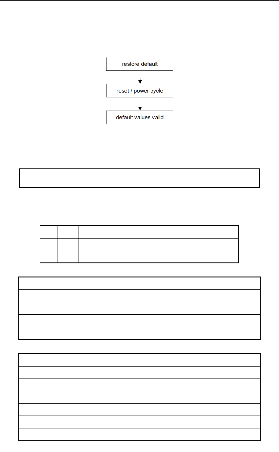
CANopen application layer and communication profile
© CiA 2011 – All rights reserved 103
initiate response). If the restoring failed, the CANopen device shall respond with the SDO abort
transfer service (abort code: 0606 0000
h
). If a wrong signature is written, the CANopen device
shall refuse to restore the defaults and shall respond with the SDO abort transfer service (abort
code: 0800 002x
h
).
The default values shall be set valid after the CANopen device is reset (NMT service reset node
for sub-index from 01
h
to 7F
h
, NMT service reset communication for sub-index 02
h
) or power
cycled.
Figure 58: Restore procedure
On read access to the appropriate sub-index the CANopen device shall provide information about
its default parameter restoring capability with the following format:
31 1 0
reserved
(000 0000 0000 0000 0000 0000 0000 0000
b
)
cmd
MSB LSB
Figure 59: Restore default read access structure
Table 57: Structure of restore read access
Bit Value Description
cmd 0
b
CANopen device does not restore default parameters
1
b
CANopen device restores parameters
OBJECT DESCRIPTION
Index 1011
h
Name restore default parameters
Object code ARRAY
Data type UNSIGNED32
Category Optional
ENTRY DESCRIPTION
Sub-index 00
h
Description highest sub-index supported
Entry category Mandatory
Access const
PDO mapping No
Value range 01
h
to 7F
h
Default value profile- or manufacturer-specific

CANopen application layer and communication profile
104 © CiA 2011 – All rights reserved
Sub-index 01
h
Description restore all default parameters
Entry category Mandatory
Access rw
PDO mapping No
Value range
see value definition
(Figure 57 for write access; Figure 59 for read access)
Default value
profile- or manufacturer-specific
Sub-index 02
h
Description restore communication default parameters
Entry category Optional
Access rw
PDO mapping No
Value range
see value definition
(Figure 57 for write access; Figure 59 for read access)
Default value
profile- or manufacturer-specific
Sub-index 03
h
Description restore application default parameters
Entry category Optional
Access rw
PDO mapping No
Value range
see value definition
(Figure 57 for write access; Figure 59 for read access)
Default value profile- or manufacturer-specific
Sub-index 04
h
to 7F
h
Description restore manufacturer defined default parameters
Entry category Optional
PDO mapping No
Value range
see value definition
(Figure 57 for write access; Figure 59 for read access)
Default value profile- or manufacturer-specific

CANopen application layer and communication profile
© CiA 2011 – All rights reserved 105
7.5.2.15 Object 1012
h
: COB-ID time stamp object
This object shall indicate the configured COB-ID of the Time-Stamp Object (TIME). Further, it defines
whether the CANopen device consumes the TIME or whether the CANopen device generates the
TIME. The structure of this object is specified in Figure 60 and Table 58.
VALUE DEFINITION
31 30 29 28 11 10 0
consume produce frame
0 0000
h
11-bit CAN-ID
29-bit CAN-ID
MSB LSB
Figure 60: Structure of TIME COB-ID
Table 58: Description of TIME COB-ID
Bit(s)
Value
Description
consume 0
b
CANopen device does not consume TIME message
1
b
CANopen device consumes TIME message
produce 0
b
CANopen device does not produce TIME message
1
b
CANopen device produces TIME message
frame 0
b
11-bit CAN-ID valid (CAN base frame)
1
b
29-bit CAN-ID valid (CAN extended frame)
29-bit CAN-ID x 29-bit CAN-ID of the CAN extended frame
11-bit CAN-ID x 11-bit CAN-ID of the CAN base frame
Bits 29 (frame), 30 (produce) may be static (not changeable). If a CANopen device is not able to
generate TIME messages, an attempt to set bit 30 (produce) to 1
b
shall be responded with the
SDO abort transfer service (abort code: 0609 0030
h
). CANopen devices supporting the CAN base
frame type only, an attempt to set bit 29 (frame) to 1
b
shall be responded with the SDO abort
transfer service (abort code: 0609 0030
h
). The bits 0 to 29 shall not be changed, while the object
exists (bit 30 = 1
b
or bit 31 = 1
b
).
OBJECT DESCRIPTION
Index 1012
h
Name COB-ID time stamp message
Object code VAR
Data type UNSIGNED32
Category Optional
ENTRY DESCRIPTION
Sub-index 00
h
Access rw
PDO mapping
No
Value range UNSIGNED32
Default value CAN-ID: 100
h
frame: 0
b
valid: profile- or manufacturer-specific

CANopen application layer and communication profile
106 © CiA 2011 – All rights reserved
7.5.2.16 Object 1013
h
: High resolution time stamp
This object shall indicate the configured high resolution time stamp. It may be mapped into a PDO in
order to exchange a high resolution time stamp message. Further application specific use is
encouraged.
VALUE DEFINITION
The value is given in multiples of 1 µs.
OBJECT DESCRIPTION
Index 1013
h
Name high resolution time stamp
Object code VAR
Data type UNSIGNED32
Category Optional
ENTRY DESCRIPTION
Sub-index 00
h
Access rw;
ro, if only high resolution time stamp producer is supported
rw or wo, if only high resolution time stamp consumer is supported
PDO mapping Optional
Value range UNSIGNED32
Default value 0
7.5.2.17 Object 1014
h
: COB-ID EMCY
This object shall indicate the configured COB-ID for the EMCY write service.
VALUE DEFINITION
31 30 29 28 11 10 0
valid
0
b
frame
0 0000
h
11-bit CAN-ID
29-bit CAN-ID
MSB LSB
Figure 61: Structure of the EMCY Identifier
Table 59: Description of EMCY COB-ID
Bit(s) Value Description
valid
0
b
EMCY exists / is valid
1
b
EMCY does not exist / is not valid
30 0
b
reserved (always 0
b
)
frame 0
b
11-bit CAN-ID valid (CAN base frame)
1
b
29-bit CAN-ID valid (CAN extended frame)
29-bit CAN-ID x 29-bit CAN-ID of the CAN extended frame
11-bit CAN-ID x 11-bit CAN-ID of the CAN base frame

CANopen application layer and communication profile
© CiA 2011 – All rights reserved 107
CANopen devices supporting the CAN base frame type only shall respond with the SDO abort
transfer service (abort code: 0609 0030
h
) in the case of an attempt to set bit 29 (frame) to 1
b
. The
bits 0 to 29 shall not be changed, while the object exists and is valid (bit 31 = 0
b
).
OBJECT DESCRIPTION
Index 1014
h
Name COB-ID emergency message
Object code VAR
Data type UNSIGNED32
Category Conditional;
Mandatory, if Emergency is supported
ENTRY DESCRIPTION
Sub-index 00
h
Access rw;
const, if COB-ID is not changeable
PDO mapping No
Value range UNSIGNED32
Default value CAN-ID: 80
h
+ Node-ID
frame: 0
b
valid: profile- or manufacturer-specific
7.5.2.18 Object 1015
h
: Inhibit time EMCY
This object shall indicate the configured inhibit time for the EMCY message.
VALUE DEFINITION
The value shall be given in multiples of 100 µs. The value 0 shall disable the inhibit time.
OBJECT DESCRIPTION
Index 1015
h
Name inhibit time EMCY
Object code VAR
Data type UNSIGNED16
Category Optional
ENTRY DESCRIPTION
Sub-index 00
h
Access rw
PDO mapping No
Value range UNSIGNED16
Default value 0
7.5.2.19 Object 1016
h
: Consumer heartbeat time
The consumer heartbeat time object shall indicate the expected heartbeat cycle times. Monitoring of
the heartbeat producer shall start after the reception of the first heartbeat.

CANopen application layer and communication profile
108 © CiA 2011 – All rights reserved
NOTE: The consumer heartbeat time should be higher than the corresponding producer heartbeat
time.
NOTE: Before the reception of the first heartbeat the status of the heartbeat producer is unknown.
VALUE DEFINITION
31 24 23 16 15 0
reserved
(00
h
)
Node-ID Heartbeat time
MSB LSB
Figure 62: Structure of Consumer heartbeat time
If the heartbeat time is 0 or the node-ID is 0 or greater than 127 the corresponding object entry
shall be not used. The heartbeat time shall be given in multiples of 1ms.
An attempt to configure several heartbeat times unequal 0 for the same node-ID the CANopen
device shall be responded with the SDO abort transfer service (abort code: 0604 0043
h
).
OBJECT DESCRIPTION
Index 1016
h
Name Consumer heartbeat time
Object code ARRAY
Data type UNSIGNED32
Category Optional
ENTRY DESCRIPTION
Sub-index 00
h
Description Highest sub-index supported
Entry category Mandatory
Access const
PDO mapping No
Value range 01
h
to 7F
h
Default value profile- or manufacturer-specific
Sub-index 01
h
Description Consumer heartbeat time
Entry category Mandatory
Access rw
PDO mapping No
Value range UNSIGNED32 (Figure 62)
Default value 0000 0000
h

CANopen application layer and communication profile
© CiA 2011 – All rights reserved 109
Sub-index 02
h
to 7F
h
Description Consumer heartbeat time
Entry category Optional
Access rw
PDO mapping No
Value range UNSIGNED32 (Figure 62)
Default value 0000 0000
h
7.5.2.20 Object 1017
h
: Producer heartbeat time
The producer heartbeat time shall indicate the configured cycle time of the heartbeat.
VALUE DEFINITION
The value shall be given in multiples of 1 ms. The value 0 shall disable the producer heartbeat.
OBJECT DESCRIPTION
Index 1017
h
Name Producer heartbeat time
Object code VAR
Data type UNSIGNED16
Category Conditional;
Mandatory, if guarding not supported
ENTRY DESCRIPTION
Sub-index 00
h
Access rw
const, if default value is profile-specific and not changeable
PDO mapping No
Value range UNSIGNED16
Default value 0 or profile-specific
7.5.2.21 Object 1018
h
: Identity object
This object shall provide general identification information of the CANopen device.
VALUE DEFINITION
Sub-index 01
h
shall contain the unique value
1
that is allocated uniquely to each vendor of a
CANopen device. The value 0000 0000
h
shall indicate an invalid vendor-ID.
Sub-index 02
h
shall contain the unique value that identifies a specific type of CANopen devices.
The value of 0000 0000
h
shall be reserved.
Sub-index 03
h
shall contain the major revision number and the minor revision number of the
revision of the CANopen device (see Figure 63). The major revision number shall identify a
specific CANopen behavior. That means if the CANopen functionality is different, the major
revision number shall be incremented. The minor revision number shall identify different versions
of CANopen device with the same CANopen behavior. The value of 0000 0000
h
shall be
reserved.
1
The value is assigned uniquely by CAN in Automation (CiA).

CANopen application layer and communication profile
110 © CiA 2011 – All rights reserved
31 16 15 0
Major revision number Minor revision number
MSB LSB
Figure 63: Structure of revision number
Sub-index 04
h
shall contain the serial number that identifies uniquely a CANopen device within a
product group and a specific revision. The value of 0000 0000
h
shall be reserved.
OBJECT DESCRIPTION
Index 1018
h
Name Identity object
Object code RECORD
Data type Identity
Category Mandatory
ENTRY DESCRIPTION
Sub-index 00
h
Description Highest sub-index supported
Entry category Mandatory
Access const
PDO mapping No
Value range 01
h
to 04
h
Default value profile- or manufacturer-specific
Sub-index 01
h
Description Vendor-ID
Entry category Mandatory
Access ro
PDO mapping No
Value range UNSIGNED32
Default value Assigned uniquely to manufacturers by CiA

CANopen application layer and communication profile
© CiA 2011 – All rights reserved 111
Sub-index 02
h
Description Product code
Entry category Optional
Access ro
PDO mapping No
Value range UNSIGNED32
Default value
Profile- or manufacturer-specific
Sub-index 03
h
Description Revision number
Entry category Optional
Access ro
PDO mapping No
Value range UNSIGNED32
Default value
Profile- or manufacturer-specific
Sub-index 04
h
Description Serial number
Entry category Optional
Access ro
PDO mapping No
Value range UNSIGNED32
Default value
Profile- or manufacturer-specific
7.5.2.22 Object 1019
h
: Synchronous counter overflow value
This object shall indicate the configured highest value the synchronous counter supports. This object
shall be implemented by the producer and the consumer, if the synchronous counter is supported by
the CANopen device. If the value is greater than 1, the SYNC message shall have a data length of 1
byte. The SYNC consumer shall ignore the value itself. An EMCY message (error code: 8240
h
–
unexpected SYNC data length) may be transmitted by a SYNC consumer in the case the configured
data length of the SYNC message does not meet the data length of a received SYNC message.

CANopen application layer and communication profile
112 © CiA 2011 – All rights reserved
VALUE DEFINITION
Value
Description
0
The SYNC message shall be transmitted as a CAN message
of data length 0.
1
reserved
2 to 240
The SYNC message shall be transmitted as a CAN message
of data length 1. The first data byte contains the counter.
241 to 255
reserved
The value used shall be the least common multiple of all the TPDO transmission types
(1 < n <= 240) used. This ensures that periodic SYNC events always happen in the SYNC cycles
with the same counter value.
A change of the value shall be responded with a SDO abort (abort code: 0800 0022
h
or
0800 0000
h
) in case the sync cycle period is unequal to 0.
OBJECT DESCRIPTION
Index 1019
h
Name Synchronous counter overflow value
Object code VAR
Data type UNSIGNED8
Category Optional
ENTRY DESCRIPTION
Sub-index 00
h
Access rw;
const, if default value is profile-specific and not changeable
PDO mapping No
Value range UNSIGNED8
Default value 0 or profile-specific
7.5.2.23 Object 1020
h
: Verify configuration
This object shall indicate the downloaded configuration date and time. If a CANopen device supports
the saving of parameters in non-volatile memory, a network configuration tool or a CANopen manager
uses this object to verify the configuration after a CANopen device reset and to check if a
reconfiguration is necessary. The configuration tool stores the date and time in that object and stores
the same values in the DCF. Now the configuration tool lets the CANopen device save its
configuration by writing to index 1010
h
sub-index 01
h
the signature "save". After a reset the CANopen
device shall restore the last configuration and the signature automatically or by request. If any other
command changes boot-up configuration values, the CANopen device shall reset the object Verify
Configuration to 0.
The Configuration Manager compares signature and configuration with the value from the DCF and
decides if a reconfiguration is necessary or not.
Note: The usage of this object allows a significant speed-up of the boot-up process. If it is used, the
system integrator considers that an user changes a configuration value and afterwards activate
the command store configuration 1010
h
without changing the value of 1020
h
. So the system
integrator ensures a 100% consequent usage of this feature.

CANopen application layer and communication profile
© CiA 2011 – All rights reserved 113
VALUE DEFINITION
Sub-index 01
h
(configuration date) shall contain the number of days since January 1, 1984.
Sub-index 02
h
(configuration time) shall be the number of ms after midnight.
OBJECT DESCRIPTION
Index 1020
h
Name Verify configuration
Object code ARRAY
Data type UNSIGNED32
Category Optional
ENTRY DESCRIPTION
Sub-index 00
h
Description Highest sub-index supported
Entry category Mandatory
Access const
PDO mapping No
Value range 02
h
Default value 02
h
Sub-index 01
h
Description Configuration date
Entry category Mandatory
Access rw
PDO mapping No
Value range UNSIGNED32
Default value Manufacturer-specific
Sub-index 02
h
Description Configuration time
Entry category Mandatory
Access rw
PDO mapping No
Value range UNSIGNED32
Default value Manufacturer-specific

CANopen application layer and communication profile
114 © CiA 2011 – All rights reserved
7.5.2.24 Object 1021
h
: Store EDS
This object shall indicate the downloaded EDS. The storage of EDS files in the CANopen device has
some advantages:
• The manufacturer has not the problem of distributing the EDS via disks
• Management of different EDS versions for different software versions is less error prone, if
they are stored together
• The complete network settings is stored in the network. This makes the task of analyzing or
reconfiguring a network easier for tools and more transparent for the users.
VALUE DEFINITION
The filename does not need to be stored since every EDS contains its own filename.
OBJECT DESCRIPTION
Index 1021
h
Name Store EDS
Object code VAR
Data type DOMAIN
Category Optional
ENTRY DESCRIPTION
Sub-index 00
h
Access ro
PDO mapping No
Value range Manufacturer-specific
Default value No
7.5.2.25 Object 1022
h
: Store format
The object shall indicate the format of the storage. This allows the usage of compressed formats. The
object describes the external behavior only.

CANopen application layer and communication profile
© CiA 2011 – All rights reserved 115
VALUE DEFINITION
Table 60: Values for EDS store formats
Value Description
00
h
/ISO10646/, not compressed
01
h
reserved
::::: :::::
7F
h
reserved
80
h
manufacturer-specific
::::: :::::
FF
h
manufacturer-specific
OBJECT DESCRIPTION
Index 1022
h
Name Store format
Object code VAR
Data type UNSIGNED16
Category Conditional;
Mandatory if store EDS is supported
ENTRY DESCRIPTION
Sub-index 00
h
Access ro
PDO mapping No
Value range UNSIGNED8
Default value No

CANopen application layer and communication profile
116 © CiA 2011 – All rights reserved
7.5.2.26 Object 1023
h
: OS command
The OS Command object shall be used as a command driven interface to programmable devices. The
contents of the command are /ISO8859/ characters or binary and are completely manufacturer-
specific. The host system puts the command into the object OS command.
VALUE DEFINITION
If a CANopen device implements this function, all sub-indices are mandatory, additional object
entries are manufacturer-specific. A new command may be entered, if status is in the range from
0 to 3: The command and all parameters shall be transmitted in one block to sub-index 01
h
. The
execution of the command shall start immediately after the completion of the transfer. The host
polls sub-index 02
h
, until it is a value from 0 to 3. It may then transfer the reply, if status is a value
of 1 or 3. The CANopen device shall return the same reply, if reply is requested more then one
time, or may change status from 1 to 0 or 3 to 2, if it is not able to buffer the reply.
OBJECT DESCRIPTION
Index 1023
h
Name OS command
Object code RECORD
Data type OS command record
Category Optional
ENTRY DESCRIPTION
Sub-index 00
h
Description Highest sub-index supported
Entry category Mandatory
Access const
PDO mapping No
Value range 03
h
Default value 03
h
Sub-index 01
h
Description Command
Entry category Mandatory
Access rw;
wo, if only writing is supported
PDO mapping No
Value range No
Default value Manufacturer-specific

CANopen application layer and communication profile
© CiA 2011 – All rights reserved 117
Sub-index 02
h
Description Status
Entry category Mandatory
Access ro
PDO mapping No
Value range UNSIGNED8
Default value No
Sub-index 03
h
Description Reply
Entry category Mandatory
Access ro
PDO mapping No
Value range No
Default value No
7.5.2.27 Object 1024
h
: OS command mode
This object shall control the command execution in the application specific queue. It is intended that
this object represent the most recent command of an application program specific queue.
VALUE DEFINITION
Table 61: OS command mode values
Value Description
00
h
Execute the next command immediately
01
h
Buffer the next command
02
h
Execute the commands in the buffer
03
h
Abort the current command and all commands in the buffer
04
h
Manufacturer-specific
::::: :::::
FF
h
Manufacturer-specific
OBJECT DESCRIPTION
Index 1024
h
Name OS command mode
Object code VAR
Data type UNSIGNED8
Category Optional

CANopen application layer and communication profile
118 © CiA 2011 – All rights reserved
ENTRY DESCRIPTION
Sub-index 00
h
Access wo
PDO mapping No
Value range
UNSIGNED8
Default value Manufacturer-specific
7.5.2.28 Object 1025
h
: OS debugger interface
This object shall provide the OS debugger interface. It is the binary command interface to the
debugger agents of the programmable CANopen device. The contents of the commands are
manufacturer-specific. This object enables the user to connect with a remote debugger.
VALUE DEFINITION
see OS command
OBJECT DESCRIPTION
Index 1025
h
Name OS debugger interface
Object code RECORD
Data type OS debug record
Category Optional
ENTRY DESCRIPTION
Sub-index 00
h
Description Highest sub-index supported
Entry category Mandatory
Access const
PDO mapping No
Value range 03
h
Default value 03
h
Sub-index 01
h
Description Command
Entry category Mandatory
Access rw;
wo, if only writing is supported
PDO mapping No
Value range No
Default value Manufacturer-specific

CANopen application layer and communication profile
© CiA 2011 – All rights reserved 119
Sub-index 02
h
Description Status
Entry category Mandatory
Access ro
PDO mapping No
Value range UNSIGNED8
Default value No
Sub-index 03
h
Description Reply
Entry category Mandatory
Access ro
PDO mapping No
Value range No
Default value No
7.5.2.29 Object 1026
h
: OS prompt
The OS prompt object is a character driven command interface to programmable CANopen devices.
The contents of the commands are manufacturer-specific. This object enables the user to have remote
keyboard control.
VALUE DEFINITION
Sub-index 01
h
StdIn is used to transmit single characters to the CANopen device by SDO or
PDO. Each new character shall be appended to the internal input queue. Answers of the
CANopen device shall be output on sub-index 02
h
StdOut. This object is mappable to an event-
driven PDO or polled by SDO. Sub-index 03
h
StdErr is used for error output. This object is
mappable to an event-driven PDO or polled by SDO.
OBJECT DESCRIPTION
Index 1026
h
Name OS prompt
Object code ARRAY
Data type UNSIGNED8
Category Optional

CANopen application layer and communication profile
120 © CiA 2011 – All rights reserved
ENTRY DESCRIPTION
Sub-index 00
h
Description Highest sub-index supported
Entry category Mandatory
Access const
PDO mapping No
Value range 02
h
to 03
h
Default value No
Sub-index 01
h
Description StdIn
Entry category Mandatory
Access wo
PDO mapping Optional
Value range UNSIGNED8
Default value Manufacturer-specific
Sub-index 02
h
Description StdOut
Entry category Mandatory
Access ro
PDO mapping Optional
Value range UNSIGNED8
Default value No
Sub-index 03
h
Description StdErr
Entry category Optional
Access ro
PDO mapping Optional
Value range UNSIGNED8
Default value No
7.5.2.30 Object 1027
h
: Module list
A common method to provide modular CANopen devices is the usage of a bus coupler that allows
connecting several combinations of modules. The object shall provide information on the currently
attached modules.

CANopen application layer and communication profile
© CiA 2011 – All rights reserved 121
VALUE DEFINITION
The consecutive sub-indexes (1 ≤ N ≤ 254) describe the corresponding modules in the order they
are attached. Each object entry shall contain a number that identifies the module. For this the
number shall be unique within all module types that are attached to this bus coupler device type.
The object entry at sub-index 00
h
shall contain the actual number of modules that are connected
to the bus coupler.
NOTE: If no module is present the value of sub-index 00
h
is 00
h
and a read access to sub-index
01
h
is responded with an SDO abort message (abort code: 0800 0024
h
or 0800 0000
h
).
OBJECT DESCRIPTION
Index 1027
h
Name Module list
Object code ARRAY
Data type UNSIGNED16
Category Conditional;
Mandatory, if modular devices supported
ENTRY DESCRIPTION
Sub-index 00
h
Description number of connected modules
Entry category Mandatory
Access const
PDO mapping No
Value range 01
h
to FE
h
Default value No
Sub-index 01
h
Description Module 1
Entry category Mandatory
Access ro
PDO mapping No
Value range UNSIGNED16
Default value No

CANopen application layer and communication profile
122 © CiA 2011 – All rights reserved
Sub-index 02
h
to FE
h
Description Module 2 to Module 254
Entry category Optional
Access ro
PDO mapping No
Value range UNSIGNED16
Default value No
7.5.2.31 Object 1028
h
: Emergency consumer object
This objects shall indicate the configured COB-IDs for the EMCY objects that the CANopen device is
consuming.
VALUE DEFINITION
31 30 29 28 11 10 0
valid res frame
0 0000
h
11-bit CAN-ID
29-bit CAN-ID
MSB LSB
Figure 64: Structure of EMCY COB-ID
Table 62: Description of EMCY COB-ID
Bit(s)
Value
Description
valid
0
b
EMCY consumer exists / is valid
1
b
EMCY consumer does not exist / is not valid
res 0
b
reserved (always 0
b
)
frame 0
b
11-bit CAN-ID valid (CAN base frame)
1
b
29-bit CAN-ID valid (CAN extended frame)
29-bit CAN-ID x 29-bit CAN-ID of the CAN extended frame
11-bit CAN-ID x 11-bit CAN-ID of the CAN base frame
CANopen devices supporting the CAN base frame type only, an attempt to set bit 29 (frame) to 1
b
shall be responded with the SDO abort transfer service (abort code: 0609 0030
h
). The bits 0 to 29
shall not be changed, while the object exists and is valid (bit 31 = 0
b
).
The Sub-index shall refer to the related node-ID.
OBJECT DESCRIPTION
Index 1028
h
Name Emergency consumer
Object code
ARRAY
Data type
UNSIGNED32
Category Optional

CANopen application layer and communication profile
© CiA 2011 – All rights reserved 123
ENTRY DESCRIPTION
Sub-index 00
h
Description Highest sub-index supported
Entry category Mandatory
Access const
PDO mapping No
Value range 01
h
to 7F
h
Default value profile- or manufacturer-specific
Sub-index 01
h
Description Emergency consumer 1
Entry category Mandatory
Access rw;
const, if emergency consumer value is not changeable
PDO mapping No
Value range
see value definition
Default value profile- or manufacturer-specific
Sub-index 02
h
to 7F
h
Description Emergency consumer 2 to 127
Entry category Optional
Access rw;
const, if emergency consumer value is not changeable
PDO mapping No
Value range
see value definition
Default value profile- or manufacturer-specific
7.5.2.32 Object 1029
h
: Error behavior object
If a serious CANopen device failure is detected in NMT state Operational, the CANopen device shall
enter by default autonomously the NMT state Pre-operational. If the object is implemented, the
CANopen device is configurable to enter alternatively the NMT state Stopped or remain in the current
NMT state. CANopen device failures shall include the following communication errors:
• Bus-off conditions of the CAN interface
• Life guarding event with the state ‘occurred’ and the reason 'time out'
• Heartbeat event with state ‘occurred’ and the reason 'time out"
Severe CANopen device errors also may be caused by CANopen device internal failures.

CANopen application layer and communication profile
124 © CiA 2011 – All rights reserved
VALUE DEFINITION
Table 63: Error class values
Value Description
00
h
Change to NMT state Pre-operational
(only if currently in NMT state Operational)
01
h
No change of the NMT state
02
h
Change to NMT state Stopped
03
h
reserved
::::: :::::
7F
h
reserved
80
h
Manufacturer-specific
::::: :::::
FF
h
Manufacturer-specific
OBJECT DESCRIPTION
Index 1029
h
Name Error behavior
Object code ARRAY
Data type UNSIGNED8
Category Optional
ENTRY DESCRIPTION
Sub-index 00
h
Description Highest sub-index supported
Entry category Mandatory
Access const
PDO mapping No
Value range 01
h
to FE
h
Default value profile- or manufacturer-specific
Sub-index 01
h
Description Communication error
Entry category Mandatory
Access rw;
const, if error behavior for communication errors is not changeable
PDO mapping No
Value range UNSIGNED8
Default value 00
h

CANopen application layer and communication profile
© CiA 2011 – All rights reserved 125
Sub-index 02
h
to FE
h
Description profile- or manufacturer-specific error
Entry category Optional
Access rw;
const, if error behavior is not changeable
PDO mapping No
Value range
see value definition
Default value profile or manufacturer-specific
7.5.2.33 Object 1200
h
to 127F
h
: SDO server parameter
In order to describe the SDOs used on a CANopen device the data type SDO Parameter is
introduced. The data type has the index 22
h
in the object dictionary. The structure is defined in clause
7.4.8.
VALUE DEFINITION
The number of supported object entries in the SDO object record is specified at sub-index 00
h
.
The values at sub-index 01
h
and sub-index 02
h
specify the COB-ID for this SDO. Sub-index 03
h
is
the node-ID of the SDO client associated to this CANopen device.
31 30 29 28 11 10 0
valid dyn frame
0 0000
h
11-bit CAN-ID
29-bit CAN-ID
MSB LSB
Figure 65: Structure of SDO server COB-ID
Table 64: Description of SDO server COB-ID
Bit(s) Value Description
valid 0
b
SDO exists / is valid
1
b
SDO does not exist / is not valid
dyn 0
b
Value is assigned statically
1
b
Value is assigned dynamically
frame 0
b
11-bit CAN-ID valid (CAN base frame)
1
b
29-bit CAN-ID valid (CAN extended frame)
29-bit CAN-ID x 29-bit CAN-ID of the CAN extended frame
11-bit CAN-ID x 11-bit CAN-ID of the CAN base frame
An SDO exists only if at both sub-index 01
h
and sub-index 02
h
the bit valid (bit 31) is set to 0
b
.
CANopen devices supporting the CAN base frame type only, an attempt to set bit 29 (frame) to 1
b
is responded with the SDO abort transfer service (abort code: 0609 0030
h
). It is not allowed to
change bits 0 to 29 while the object exists and is valid (bit 31 = 0
b
).
If the bit dyn (bit 30) of sub-index 01
h
or sub-index 02
h
is set to 1
b
the values of all sub-indices of
this object shall not be stored in non-volatile memory. The bit dyn may be used to mark dynamic
SDO connections between CANopen devices. Dynamic SDO connections are temporarily
configured. Static SDO connections are configured non-temporarily and may be saved in non-

CANopen application layer and communication profile
126 © CiA 2011 – All rights reserved
volatile memory. The CANopen manager may use the dyn bit to detect temporarily configured
SDO connections.
OBJECT DESCRIPTION
Index 1200
h
to 127F
h
Name SDO server parameter
Object code RECORD
Data type SDO parameter record
Category Conditional
Index 1200
h
: Optional
Index 1201
h
to 127F
h
: Mandatory for each additionally
supported SDO server
ENTRY DESCRIPTION
Sub-index 00
h
Description Highest sub-index supported
Entry category Mandatory
Access const
PDO mapping No
Value range Index 1200
h
: 02
h
Index 1201
h
to 127F
h
: 02
h
to 03
h
Default value profile or manufacturer-specific
Sub-index 01
h
Description COB-ID client -> server (rx)
Entry category Mandatory
Access Index 1200
h
: const
Index 1201
h
to 127F
h
: rw;
const, if defined by application profile
PDO mapping Optional
Value range
see value definition
Default value Index 1200
h
: CAN-ID: 600
h
+ Node-ID
frame: 0
b
dyn: 0
b
valid: 0
b
Index 1201
h
to 127F
h
: CAN-ID: manufacturer-specific (see clause
7.3.5)
frame: manufacturer-specific
dyn: 0
b
valid: 1
b
or defined by application profile

CANopen application layer and communication profile
© CiA 2011 – All rights reserved 127
Sub-index 02
h
Description COB-ID server -> client (tx)
Entry category Mandatory
Access Index 1200
h
: ro
Index 1201
h
to 127F
h
: rw;
const, if defined by application profile
PDO mapping Optional
Value range
see value definition
Default value Index 1200
h
: CAN-ID: 580
h
+ Node-ID
frame: 0
b
dyn: 0
b
valid: 0
b
Index 1201
h
to 127F
h
: CAN-ID: manufacturer-specific (see clause
7.3.5)
frame: manufacturer-specific
dyn: 0
b
valid: 1
b
or defined by application profile
Sub-index 03
h
Description Node-ID of the SDO client
Entry category Optional
Access rw
PDO mapping No
Value range 01
h
to 7F
h
Default value manufacturer-specific
7.5.2.34 Object 1280
h
to 12FF
h
: SDO client parameter
These objects contain the parameters for the SDOs for which the CANopen device is the SDO client. If
the object is supported, all sub-indices shall be available. Starting at index 1280
h
and subsequent
indices.
VALUE DEFINITION
The number of supported object entries in the SDO object record is specified at sub-index 00
h
.
The values at sub-index 01
h
and sub-index 02
h
specify the COB-ID for this SDO. Sub-index 03
h
is
the node-ID of the SDO server associated to this CANopen device.
31 30 29 28 11 10 0
valid dyn frame
0 0000
h
11-bit CAN-ID
29-bit CAN-ID
MSB LSB
Figure 66: Structure of SDO client COB-ID

CANopen application layer and communication profile
128 © CiA 2011 – All rights reserved
Table 65: Description of SDO client COB-ID
Bit(s) Value Description
valid 0
b
SDO exists / is valid
1
b
SDO does not exist / is not valid
dyn 0
b
Value is assigned statically
1
b
Value is assigned dynamically
frame 0
b
11-bit CAN-ID valid (CAN base frame)
1
b
29-bit CAN-ID valid (CAN extended frame)
29-bit CAN-ID x 29-bit CAN-ID of the CAN extended frame
11-bit CAN-ID x 11-bit CAN-ID of the CAN base frame
An SDO exists only if at both sub-index 01
h
and sub-index 02
h
the bit valid (bit 31) is set to 0
b
.
CANopen devices supporting the CAN base frame type only, an attempt to set bit 29 (frame) to 1
b
is responded with the SDO abort transfer service (abort code: 0609 0030
h
). It is not allowed to
change bits 0 to 29 while the object exists and is valid (bit 31 = 0
b
). CANopen devices supporting
the enabling (bit 31 = 0
b
) and disabling (bit 31 = 1
b
) of the SDO client only shall respond with the
SDO abort transfer service (abort code: 0609 0030
h
or 0800 000
h
) on an attempt to change the
values from bit 0 to bit 30.
If the bit dyn (bit 30) of sub-index 01
h
or sub-index 02
h
is set to 1
b
the values of all sub-indices of
this object shall not be stored in non-volatile memory. The bit dyn may be used to mark dynamic
SDO connections between CANopen devices. Dynamic SDO connections are temporarily
configured. Static SDO connections are configured non-temporarily and may be saved in non-
volatile memory. The CANopen manager may use the dyn bit to detect temporarily configured
SDO connections.
OBJECT DESCRIPTION
Index 1280
h
to 12FF
h
Name SDO client parameter
Object code RECORD
Data type SDO Parameter
Category Conditional;
Mandatory for each supported SDO client
ENTRY DESCRIPTION
Sub-index 00
h
Description Highest sub-index supported
Entry category Mandatory
Access const
PDO mapping No
Value range 03
h
Default value 03
h

CANopen application layer and communication profile
© CiA 2011 – All rights reserved 129
Sub-index 01
h
Description COB-ID client -> server (tx)
Entry category Mandatory
Access rw;
const, if defined by application profile
PDO mapping Optional
Value range
see value definition
Default value CAN-ID: manufacturer-specific (see clause 7.3.5)
frame: manufacturer-specific
dyn: 0
b
valid: 1
b
or defined by application profile
Sub-index 02
h
Description COB-ID server -> client (rx)
Entry category Mandatory
Access rw;
const, if defined by application profile
PDO mapping Optional
Value range
see value definition
Default value CAN-ID: manufacturer-specific (see clause 7.3.5)
frame: manufacturer-specific
dyn: 0
b
valid: 1
b
or defined by application profile
Sub-index 03
h
Description Node-ID of the SDO server
Entry category Mandatory
Access rw;
const, if value is not changeable
PDO mapping No
Value range 01
h
to 7F
h
Default value manufacturer-specific
7.5.2.35 Object 1400
h
to 15FF
h
: RPDO communication parameter
This object contains the communication parameters for the PDOs the CANopen device is able to
receive.
VALUE DEFINITION
Sub-index 00
h
contains the number of valid object entries within the record. Its value is at least
02
h
. If inhibit time supported the value is 03
h
and if event timer is supported the value is 05
h
.
Sub-index 01
h
contains the COB-ID of the RPDO (see Figure 67 and Table 66).

CANopen application layer and communication profile
130 © CiA 2011 – All rights reserved
31 30 29 28 11 10 0
valid reserved frame
0 0000
h
11-bit CAN-ID
29-bit CAN-ID
MSB LSB
Figure 67: Structure of RPDO COB-ID
Table 66: Description of RPDO COB-ID
Bit(s) Value Description
valid
0
b
PDO exists / is valid
1
b
PDO does not exist / is not valid
reserved x
do not care
frame 0
b
11-bit CAN-ID valid (CAN base frame)
1
b
29-bit CAN-ID valid (CAN extended frame)
29-bit CAN-ID x 29-bit CAN-ID of the CAN extended frame
11-bit CAN-ID x 11-bit CAN-ID of the CAN base frame
The bit valid (bit 31) allows selecting which RPDOs are used in the NMT state Operational.
There may be PDOs fully configured (e.g. by default) but not used, and therefore set to "not
valid" (deleted). The feature is necessary for CANopen devices supporting more than
4 RPDOs, because each CANopen device has only default CAN-IDs for the first four RPDOs
in the generic pre-defined connection set. CANopen devices supporting the CAN base frame
type only an attempt to set bit 29 (frame) to 1
b
is responded with the SDO abort transfer
service (abort code: 0609 0030
h
). It is not allowed to change bit 0 to 29 while the PDO exists
and is valid (bit 31 = 0
b
). CANopen devices supporting the enabling (bit 31 = 0
b
) and
disabling (bit 31 = 1
b
) of an RPDO only shall respond with the SDO abort transfer service
(abort code: 0609 0030
h
or 0800 000
h
) on an attempt to change the values from bit 0 to bit
30.
If the CANopen device has implemented one or more device profiles the generic pre-defined
connection set shall apply (see Table 67).
Table 67: Generic pre-defined connection set for RPDO
Index Default value
1400
h
CAN-ID: 200
h
+ Node-ID
frame: 0
b
reserved: manufacturer-specific
valid: profile or manufacturer-specific
1401
h
CAN-ID: 300
h
+ Node-ID
29-bit: 0
b
reserved: manufacturer-specific
valid: profile or manufacturer-specific
1402
h
CAN-ID: 400
h
+ Node-ID
frame: 0
b
reserved: manufacturer-specific
valid: profile- or manufacturer-specific
1403
h
CAN-ID: 500
h
+ Node-ID
frame: 0
b
reserved: manufacturer-specific
valid: profile- or manufacturer-specific

CANopen application layer and communication profile
© CiA 2011 – All rights reserved 131
Index Default value
1404
h
to
15FF
h
CAN-ID: profile- or manufacturer-specific (see clause 7.3.5)
frame: profile- or manufacturer-specific
reserved: manufacturer-specific
valid: 1
b
or defined by application proflie
If the CANopen device has implemented an application profile the specific pre-defined
connection set of that application profile shall apply.
Sub-index 02
h
defines the reception character of the RPDO (see Table 68). An attempt to change
the value of the transmission type to any not supported value shall be responded with the SDO
abort transfer service (abort code: 0609 0030
h
).
Table 68: Description of RPDO transmission type
Value
Description
00
h
synchronous
:::::
:::::
F0
h
synchronous
F1
h
reserved
:::::
:::::
FD
h
reserved
FE
h
event-driven (manufacturer-specific)
FF
h
event-driven (device profile and application profile specific)
• Synchronous means that the CANopen device shall actuate the received data with the
reception of the next SYNC (see Figure 68).
• Event-driven means that the PDO may be received at any time. The CANopen device
will actualize the data immediately.
•
Figure 68: Bus synchronization and actuation
Sub-index 03
h
contains the inhibit time. The value is defined as multiple of 100 µs. The value of 0
shall disable the inhibit time. It is not allowed to change the value while the PDO exists (bit 31 of
sub-index 01
h
is set to 0
b
). The RPDO may use the time implementation specific.
Sub-index 04
h
is reserved. It shall not be implemented; in this case read or write access leads to
the SDO abort transfer service (abort code: 0609 0011
h
).

CANopen application layer and communication profile
132 © CiA 2011 – All rights reserved
Sub-index 05
h
contains the event-timer. The value is defined as multiple of 1 ms. The value of 0
shall disable the event-timer. The RPDO may use the time for deadline monitoring. The deadline
monitoring is activated within the next reception of an RPDO after configuring the event-timer. A
timeout results in an indication to the local application.
Sub-index 06
h
contains the SYNC start value. This is not used by RPDOs. It shall not be
implemented; in this case read or write access shall lead to the SDO abort transfer service (abort
code: 0609 0011
h
).
OBJECT DESCRIPTION
Index 1400
h
to 15FF
h
Name RPDO communication parameter
Object code RECORD
Data type PDO communication parameter record
Category Conditional;
Mandatory for each supported RPDO
ENTRY DESCRIPTION
Sub-index 00
h
Description highest sub-index supported
Entry category Mandatory
Access const
PDO mapping No
Value range 02
h
to 06
h
Default value
No
Sub-index 01
h
Description COB-ID used by RPDO
Entry category Mandatory
Access rw;
const, if COB-ID is not changeable
PDO mapping No
Value range
see value definition
Default value
see value definition

CANopen application layer and communication profile
© CiA 2011 – All rights reserved 133
Sub-index 02
h
Description transmission type
Entry category Mandatory
Access rw;
const, if transmission type is not changeable
PDO mapping No
Value range
see value definition
Default value
Profile- or manufacturer specific
Sub-index 03
h
Description inhibit time
Entry category Optional
Access rw;
const, if inhibit time is not changeable
PDO mapping No
Value range
see value definition
Default value Profile- or manufacturer specific
Sub-index 04
h
Description compatibility entry
Entry category Optional
Access rw
PDO mapping No
Value range UNSIGNED8
Default value Manufacturer specific
Sub-index 05
h
Description event-timer
Entry category Optional
Access rw;
const, if event timer is not changeable
PDO mapping No
Value range
see value definition
Default value
Profile- or manufacturer specific

CANopen application layer and communication profile
134 © CiA 2011 – All rights reserved
Sub-index 06
h
Description SYNC start value
Entry category Optional
Access rw
const, if SYNC start value is not changeable
PDO mapping No
Value range UNSIGNED8
Default value Profile- or manufacturer specific
7.5.2.36 Object 1600
h
to 17FF
h
: RPDO mapping parameter
This object contains the mapping parameters for the PDOs the CANopen device is able to receive.
VALUE DEFINITION
Sub-index 00
h
contains the number of valid object entries within the mapping record or a specific
value (see Table 69), e.g. if MPDO is supported. The number of valid object entries shall be the
number of the application objects that shall be received with the corresponding RPDO.
Table 69: RPDO mapping values
Value Description
00
h
Mapping disabled
01
h
Sub-index 01
h
valid
02
h
Sub-index 01
h
and 02
h
valid
03
h
Sub-index from 01
h
to 03
h
valid
04
h
Sub-index from 01
h
to 04
h
valid
::::: :::::
40
h
Sub-index from 01
h
to 40
h
valid
41
h
reserved
::::: :::::
FD
h
reserved
FE
h
SAM-MPDO
FF
h
DAM-MPDO
Sub-index from 01
h
to 40
h
contains the information of the mapped application objects. The object
describes the content of the PDO by their index, sub-index and length (see Figure 69 and Figure 70).
The length contains the length of the application object in bit. This may be used to verify the mapping.
31 16 15 8 7 0
Index Sub-index Length
MSB LSB
Figure 69: Structure of RPDO mapping
An attempt to change the value of an object entry to any value that is not supported shall be
responded with the SDO abort transfer service. The cause for a not supported value could be the
mapping (index and sub-index) of a non-existing application object, a wrong length for the
mapped application object, or a wrong length for the PDO at all. The index and sub-index may

CANopen application layer and communication profile
© CiA 2011 – All rights reserved 135
reference a simple data type (see Table 44) for the so-called dummy mapping. This may be used
if no appropriate application object is available and to fill up the length of the RPDO to fit the
length to the according TPDO.
The following procedure shall be used for re-mapping, which may take place during the NMT
state Pre-operational and during the NMT state Operational, if supported:
1. Destroy RPDO by setting bit valid to 1
b
of sub-index 01
h
of the according RPDO
communication parameter.
2. Disable mapping by setting sub-index 00
h
to 00
h
.
3. Modify mapping by changing the values of the corresponding sub-indices.
4. Enable mapping by setting sub-index 00
h
to the number of mapped objects.
5. Create RPDO by setting bit valid to 0
b
of sub-index 01
h
of the according RPDO
communication parameter.
If during step 3 the CANopen device detects that index and sub-index of the mapped object does
not exist or the object cannot be mapped the CANopen device shall respond with the SDO abort
transfer service (abort code: 0602 0000
h
or 0604 0041
h
).
If during step 4 the CANopen device detects that the RPDO mapping is not valid or not possible
the CANopen device shall respond with the SDO abort transfer service (abort code: 0602 0000
h
or 0604 0042
h
).
If the CANopen device receives a PDO that is having more data bytes than the number of
mapped data bytes is (length), then the CANopen device shall use the first data bytes up to the
length and may be initiate the EMCY write service, if supported.
If a CANopen device receives a PDO that is having less data bytes than the number of mapped data
bytes (length), then the CANopen device shall initiate the EMCY write service, if supported, with the
error code 8210
h
.
Figure 70: Principle of RPDO mapping
OBJECT DESCRIPTION
Index 1600
h
to 17FF
h
Name RPDO mapping parameter
Object code RECORD
Data type PDO mapping parameter record
Category Conditional;
Mandatory for each supported PDO

CANopen application layer and communication profile
136 © CiA 2011 – All rights reserved
ENTRY DESCRIPTION
Sub-index 00
h
Description number of mapped application objects in PDO
Entry category Mandatory
Access rw;
const, if mapping is not changeable
PDO mapping No
Value range
see value definition
Default value
profile- or manufacturer-specific
Sub-index 01
h
Description 1
st
application object
Entry category Mandatory
Access rw;
const, if mapping entry is not changeable
PDO mapping No
Value range
see value definition
Default value profile- or manufacturer-specific
Sub-index 02
h
to 40
h
Description 2
nd
application object to 64
th
application object
Entry category Optional
Access rw;
const, if mapping entry is not changeable
PDO mapping No
Value range
see value definition
Default value profile- or manufacturer-specific
7.5.2.37 Object 1800
h
to 19FF
h
: TPDO communication parameter
This object contains the communication parameters for the PDOs the CANopen device is able to
transmit.
VALUE DEFINITION
Sub-index 00
h
contains the number of valid object entries within the record. Its value is at least
02
h
. If inhibit time supported the value is 03
h
and if event timer is supported the value is 05
h
.
Sub-index 01
h
contains the COB-ID of the TPDO (see Figure 71 and Table 70).

CANopen application layer and communication profile
© CiA 2011 – All rights reserved 137
31 30 29 28 11 10 0
valid RTR frame
0 0000
h
11-bit CAN-ID
29-bit CAN-ID
MSB LSB
Figure 71: Structure of TPDO COB-ID
Table 70: Description of TPDO COB-ID
Bit(s) Value Description
valid
0
b
PDO exists / is valid
1
b
PDO does not exist / is not valid
RTR 0
b
RTR allowed on this PDO
1
b
no RTR allowed on this PDO
frame 0
b
11-bit CAN-ID valid (CAN base frame)
1
b
29-bit CAN-ID valid (CAN extended frame)
29-bit CAN-ID x 29-bit CAN-ID of the CAN extended frame
11-bit CAN-ID x 11-bit CAN-ID of the CAN base frame
The bit valid (bit 31) allows selecting which TPDOs are used in the NMT state Operational.
There may be PDOs fully configured (e.g. by default) but not used, and therefore set to "not
valid" (deleted). The feature is necessary for CANopen devices supporting more than
4 TPDOs, because each CANopen device has only default CAN-IDs for the first four TPDOs
in the generic pre-defined connection set. CANopen devices supporting the CAN base frame
type only or do not support RTRs, an attempt to set bit 29 (frame) to 1
b
or bit 30 (RTR) to 0
b
is responded with the SDO abort transfer service (abort code: 0609 0030
h
). It is not allowed
to change bit from 0 to 29 while the PDO exists and is valid (bit 31 = 0
b
). CANopen devices
supporting the enabling (bit 31 = 0
b
) and disabling (bit 31 = 1
b
) of a TPDO only shall respond
with the SDO abort transfer service (abort code: 0609 0030
h
or 0800 000
h
) on an attempt to
change the values from bit 0 to bit 30.
If the CANopen device has implemented one or more device profiles the generic pre-defined
connection set shall apply (see Table 67).
Table 71: Generic pre-defined connection set for TPDO
Index Default value
1800
h
CAN-ID: 180
h
+ Node-ID
frame: 0
b
RTR: profile- or manufacturer-specific
valid: profile- or manufacturer-specific
1801
h
CAN-ID: 280
h
+ Node-ID
frame: 0
b
RTR: profile- or manufacturer-specific
valid: profile- or manufacturer-specific
1802
h
CAN-ID: 380
h
+ Node-ID
frame: 0
b
RTR: profile- or manufacturer-specific
valid: profile- or manufacturer-specific

CANopen application layer and communication profile
138 © CiA 2011 – All rights reserved
Index Default value
1803
h
CAN-ID: 480
h
+ Node-ID
frame: 0
b
RTR: profile- or manufacturer-specific
valid: profile- or manufacturer-specific
1804
h
to
19FF
h
CAN-ID: profile- or manufacturer-specific (see clause 7.3.5)
frame: profile- or manufacturer-specific
RTR: profile- or manufacturer-specific
valid: 1
b
or defined by application profile
If the CANopen device has implemented an application profile the specific pre-defined
connection set of that application profile shall apply.
Sub-index 02
h
defines the transmission character of the TPDO (see Table 72). An attempt to
change the value of the transmission type to any not supported value shall be responded with the
SDO abort transfer service (abort code: 0609 0030
h
).
Table 72: Description of TPDO transmission type
Value
Description
00
h
synchronous (acyclic)
01
h
synchronous (cyclic every sync)
02
h
synchronous (cyclic every 2
nd
SYNC)
03
h
synchronous (cyclic every 3
rd
SYNC)
04
h
synchronous (cyclic every 4
th
SYNC)
:::::
:::::
F0
h
synchronous (cyclic every 240
th
SYNC)
F1
h
reserved
:::::
:::::
FB
h
reserved
FC
h
RTR-only (synchronous)
FD
h
RTR-only (event-driven)
FE
h
event-driven (manufacturer-specific)
FF
h
event-driven (device profile and application profile specific)
• Synchronous means that the PDO is transmitted after the SYNC. The CANopen device
will start sampling of the data with the reception of the SYNC (see Figure 72). In case it
is acyclic the CANopen device internal event is given and with the next SYNC the
sampling is started and the PDO is transmitted afterwards. In case it is cyclic the
sampling is started with the reception of every SYNC, every 2
nd
SYNC, every 3
rd
SYNC,
and s.o. depending on the given value and the PDO is transmitted afterwards.

CANopen application layer and communication profile
© CiA 2011 – All rights reserved 139
• RTR-only means that the PDO is not transmitted normally it shall be requested via RTR.
In case it is synchronous the CANopen device will start sampling with the reception of
every SYNC and then will buffer the PDO (see Figure 72). In case it is event-driven the
CANopen device will start sampling with the reception of the RTR and will transmit the
PDO immediately.
• Event-driven means that the PDO may be transmitted at any time based on the
occurrence of a CANopen device internal event. The definition of the event does not fall
into the scope of this specification and may be specified in device profiles and
application profiles..
•
Figure 72: Bus synchronization and sampling
Sub-index 03
h
contains the inhibit time. The time is the minimum interval for PDO transmission if
the transmission type is set to FE
h
and FF
h
. The value is defined as multiple of 100 µs. The value
of 0 shall disable the inhibit time. The value shall not be changed while the PDO exists (bit 31 of
sub-index 01
h
is set to 0
b
).
Sub-index 04
h
is reserved. It does shall not be implemented; in this case read or write access
leads to the SDO abort transfer service (abort code: 0609 0011
h
).
Sub-index 05
h
contains the event-timer. The time is the maximum interval for PDO transmission if
the transmission type is set to FE
h
and FF
h
. The value is defined as multiple of 1 ms. The value of
0 shall disable the event-timer.
Sub-index 06
h
contains the SYNC start value. The SYNC start value of 0 shall indicate that the
counter of the SYNC message shall not be processed for this PDO. The SYNC start value 1 to
240 shall indicate that the counter of the SYNC message shall be processed for this PDO. In
case the counter of the SYNC message is not enabled (see 7.5.2.22) sub-index 06
h
shall be
ignored. The SYNC message of which the counter value equals the SYNC start value shall be
regarded as the first received SYNC message. The value shall not be changed while the PDO
exists (bit 31 of sub-index 01
h
is set to 0
b
).
NOTE if the CANopen device detects on switch into the NMT state operational that the SYNC
counter value received is higher than the SYNC start value, then the CANopen device has to wait
a full cycle until the correct SYNC counter is received.
OBJECT DESCRIPTION
Index 1800
h
to 19FF
h
Name TPDO communication parameter
Object code RECORD
Data type PDO communication parameter record
Category Conditional;
Mandatory for each supported TPDO

CANopen application layer and communication profile
140 © CiA 2011 – All rights reserved
ENTRY DESCRIPTION
Sub-index 00
h
Description highest sub-index supported
Entry category Mandatory
Access const
PDO mapping No
Value range 02
h
to 05
h
Sub-index 01
h
Description COB-ID used by TPDO
Entry category Mandatory
Access rw;
const, if COB-ID is not changeable
PDO mapping No
Value range
see value definition
Default value see value definition
Sub-index 02
h
Description transmission type
Entry category Mandatory
Access rw;
const, if transmission type is not changeable
PDO mapping No
Value range
see value definition
Default value
profile- or manufacturer-specific
Sub-index 03
h
Description inhibit time
Entry category Optional
Access rw;
const, if inhibit time is not changeable
PDO mapping No
Value range
see value definition
Default value profile- or manufacturer-specific

CANopen application layer and communication profile
© CiA 2011 – All rights reserved 141
Sub-index 04
h
Description reserved
Entry category Optional
Access rw
PDO mapping No
Value range UNSIGNED8
Default value manufacturer-specific
Sub-index 05
h
Description event timer
Entry category Optional
Access rw;
const, if event timer is not changeable
PDO mapping No
Value range
see value definition
Default value
profile- or manufacturer-specific
Sub-index 06
h
Description SYNC start value
Entry category Optional
Access rw;
const, if SYNC start value is not changeable
PDO mapping No
Value range UNSIGNED8
Default value profile- or manufacturer-specific
7.5.2.38 Object 1A00
h
to 1BFF
h
: TPDO mapping parameter
This object contains the mapping for the PDOs the device is able to transmit.
VALUE DEFINITION
Sub-index 00
h
contains the number of valid object entries within the mapping record or a specific
value (see Table 73), e.g. if MPDO is supported. The number of valid object entries shall be the
number of the application objects that shall be transmitted with the corresponding TPDO.
Table 73: TPDO mapping values
Value Description
00
h
Mapping disabled
01
h
Sub-index 01
h
valid
02
h
Sub-index 01
h
and 02
h
valid
03
h
Sub-index from 01
h
to 03
h
valid

CANopen application layer and communication profile
142 © CiA 2011 – All rights reserved
Value Description
04
h
Sub-index from 01
h
to 04
h
valid
::::: :::::
40
h
Sub-index from 01
h
to 40
h
valid
41
h
reserved
::::: :::::
FD
h
reserved
FE
h
SAM-MPDO
FF
h
DAM-MPDO
Sub-index from 01
h
to 40
h
contains the information of the mapped application objects. The object
describes the content of the PDO by their index, sub-index and length (see Figure 73 and Figure 74).
The length contains the length of the application object in bit. This may be used to verify the mapping.
31 16 15 8 7 0
Index Sub-index Length
MSB LSB
Figure 73: Structure of TPDO mapping
An attempt to change the value of an object entry to any value that is not supported shall be
responded with the SDO abort transfer service. The cause for a not supported value could be the
mapping (index and sub-index) of a non-existing application object, a wrong length for the
mapped application object, or a wrong length for the PDO at all.
The following procedure shall be used for re-mapping, which may take place during the NMT
state Pre-operational and during the NMT state Operational, if supported:
1. Destroy TPDO by setting bit valid to 1
b
of sub-index 01
h
of the according TPDO
communication parameter.
2. Disable mapping by setting sub-index 00
h
to 00
h
.
3. Modify mapping by changing the values of the corresponding sub-indices.
4. Enable mapping by setting sub-index 00
h
to the number mapped objects.
5. Create TPDO by setting bit valid to 0
b
of sub-index 01
h
of the according TPDO
communication parameter.
If during step 3 the CANopen device detects that index and sub-index of the mapped object does
not exist or the object cannot be mapped the CANopen device shall respond with the SDO abort
transfer service (abort code: 0602 0000
h
or 0604 0041
h
).
If during step 4 the CANopen device detects that the RPDO mapping is not valid or not possible
the CANopen device shall respond with the SDO abort transfer service (abort code: 0602 0000
h
or 0604 0042
h
).

CANopen application layer and communication profile
© CiA 2011 – All rights reserved 143
Figure 74: Principle of TPDO mapping
OBJECT DESCRIPTION
Index 1A00
h
to 1BFF
h
Name TPDO mapping
Object code RECORD
Data type PDO mapping parameter record
Category Conditional;
Mandatory for each supported PDO
ENTRY DESCRIPTION
Sub-index 00
h
Description number of mapped application objects in TPDO
Entry category Mandatory
Access rw;
const, if PDO mapping is not changeable
PDO mapping No
Value range
see value definition
Default value profile- or manufacturer-specific

CANopen application layer and communication profile
144 © CiA 2011 – All rights reserved
Sub-index 01
h
Description 1
st
application object
Entry category Mandatory
Access rw;
const, if PDO mapping entry is not changeable
PDO mapping No
Value range
see value definition
Default value profile- or manufacturer-specific
Sub-index 02
h
to 40
h
Description 2
nd
application object to 64
th
application object
Entry category Optional
Access rw;
const, if PDO mapping entry is not changeable
PDO mapping No
Value range
see value definition
Default value
profile- or manufacturer-specific
7.5.2.39 Object 1FA0
h
to 1FCF
h
: Object scanner list
The producer of an SAM-MPDO uses the object scanner list to configure, which objects shall be
transmitted.
VALUE DEFINITION
Each object entry describes an object that may be sent via the MPDO. It is possible to describe
consecutive sub-indexes by setting the parameter block size to the number of sub-indexes that
shall follow.
Object entries that are not configured shall have the value 0.
Figure 75: Object scanner list object entry
OBJECT DESCRIPTION
Index 1FA0
h
to 1FCF
h
Name Object scanner list
Object code ARRAY
Data type UNSIGNED32
Category Optional
31 24 23 16 15 8 7 0
Block size Index Sub-index
MSB LSB

CANopen application layer and communication profile
© CiA 2011 – All rights reserved 145
ENTRY DESCRIPTION
Sub-index 00
h
Description Highest sub-index supported
Entry category Mandatory
Access const
PDO mapping No
Value range 01
h
to FE
h
Default value profile- or manufacturer-specific
Sub-index 01
h
Description Scan 1
Entry category Mandatory
Access rw;
ro or const, if Scan entry is not changeable
PDO mapping No
Value range
see value definition
Default value profile- or manufacturer-specific
Sub-index 02
h
to FE
h
Description Scan 2 to Scan 254
Entry category Optional
Access rw;
ro or const, if Scan entry is not changeable
PDO mapping No
Value range
see value definition
Default value profile- or manufacturer-specific
7.5.2.40 Object 1FD0
h
to 1FFF
h
: Object dispatching list
The consumer of an SAM-MPDO uses the object dispatching list as a cross reference between the
remote object of the producer and local object dictionary.
VALUE DEFINITION
63 56 55 40 39 32 31 16 15 8 7 0
Block size Local index
Local sub-
index
Sender index
Sender
sub-index
Sender
node-ID
MSB LSB
Figure 76: Object dispatching list object entry
Each object entry describes how the data of a received MPDO is transferred to the local object
dictionary. If the flag field is 0 and the producer node-ID, the producer Index and producer sub-

CANopen application layer and communication profile
146 © CiA 2011 – All rights reserved
index fit to the object entry, and then the data shall be written to the local object addressed by the
values local index and local sub-index of that object entry.
The parameter block size allows the description of consecutive sub-indexes to be used. Example:
if sub-index 1-9 of the sender shall be mapped to sub-index 11-19 of the receiver, this range is
defined by
Sender Sub-index = 1
Local Sub-index = 11
Block Size = 9
Object entries that are not configured shall have the value 0.
OBJECT DESCRIPTION
Index 1FD0
h
to 1FFF
h
Name Object dispatching list
Object code ARRAY
Data type UNSIGNED64
Category Optional
ENTRY DESCRIPTION
Sub-index 00
h
Description Highest sub-index support
Entry category Mandatory
Access const
PDO mapping No
Value range 01
h
to FE
h
Default value
profile- or manufacturer-specific
Sub-index 01
h
Description Dispatch 1
Entry category Mandatory
Access rw;
ro or const, if dispatch entry is not changeable
PDO mapping No
Value range UNSIGNED64
Default value profile- or manufacturer-specific

CANopen application layer and communication profile
© CiA 2011 – All rights reserved 147
Sub-index 02
h
to FE
h
Description Dispatch 2 to Dispatch 254
Entry category Optional
Access rw;
ro or const, if dispatch entry is not changeable
PDO mapping No
Value range UNSIGNED64
Default value profile- or manufacturer-specific

CANopen application layer and communication profile
148 © CiA 2011 – All rights reserved
Annex A (informative)
Implementation Recommendations
When implementing the protocols, the following rules shall be obeyed to guarantee interoperability.
These rules deal with the following implementation aspects:
Invalid COB's
A COB is invalid if it has a COB-ID that is used by the specified protocols, but it contains invalid
parameter values according to the protocol specification. This may only be caused by errors in the
lower layers or implementation errors. Invalid COB's shall be handled locally in an implementation
specific way that does not fall within the scope of this specification. As far as the protocol is
concerned, an invalid COB shall be ignored.
Time-out's
Since COB's may be ignored, the response of a confirmed service may never arrive. To resolve this
situation, an implementation may, after a certain amount of time, indicate this to the service user
(time-out). A time-out is not a confirmation of that service. A time-out indicates that the service has not
completed yet. The application may deal with this situation. Time-out values are considered to be
implementation specific and do not fall within the scope of this specification. However, it is
recommended that an implementation provides facilities to adjust these time-out values to the
requirements of the application.
PDO Transmission Type 0, 254, 255
Transmit PDOs with these transmission types may be sent immediately for transmission type 254 and
255 or with the first Sync for transmission type 0 after entering the operational state, if not specified
differently in the corresponding profiles.
Overview object dictionary objects for communication
Table 74: Standard objects
Index Object Name Data type Acc.
2
M/O
1000
h
VAR device type UNSIGNED32 ro M
1001
h
VAR error register UNSIGNED8 ro M
1002
h
VAR manufacturer status register UNSIGNED32 ro O
1003
h
ARRAY pre-defined error field UNSIGNED32 ro O
1004
h
reserved for compatibility reasons
1005
h
VAR COB-ID SYNC UNSIGNED32 rw O
1006
h
VAR communication cycle period UNSIGNED32 rw O
1007
h
VAR synchronous window length UNSIGNED32 rw O
1008
h
VAR manufacturer device name VIS-STRING const O
1009
h
VAR manufacturer hardware version VIS-STRING const O
100A
h
VAR manufacturer software version VIS-STRING const O
100B
h
reserved for compatibility reasons
100C
h
VAR guard time UNSIGNED16 rw O
100D
h
VAR life time factor UNSIGNED8 rw O
2
Access type listed here may vary for certain sub-indices. See detailed object specification.

CANopen application layer and communication profile
© CiA 2007 – All rights reserved 149
100E
h
reserved for compatibility reasons
100F
h
reserved for compatibility reasons
1010
h
ARRAY store parameters UNSIGNED32 rw O
1011
h
ARRAY restore default parameters UNSIGNED32 rw O
1012
h
VAR COB-ID TIME UNSIGNED32 rw O
1013
h
VAR high resolution time stamp UNSIGNED32 rw O
1014
h
VAR COB-ID EMCY UNSIGNED32 rw O
1015
h
VAR Inhibit Time EMCY UNSIGNED16 rw O
1016
h
ARRAY Consumer heartbeat time UNSIGNED32 rw O
1017
h
VAR Producer heartbeat time UNSIGNED16 rw O
1018
h
RECORD Identity Object IDENTITY (23
h
) ro M
1019
h
VAR Synchronous counter overflow value UNSIGNED8 rw O
Device configuration
1020
h
ARRAY Verify configuration UNSIGNED32 rw O
EDS storage
1021
h
VAR Store EDS DOMAIN rw O
1022
h
VAR Storage format UNSIGNED8 rw O
OS command and prompt
1023
h
RECORD OS command COMMANDPAR (25
h
) rw O
1024
h
VAR OS command mode UNSIGNED8 wo O
1025
h
RECORD OS debugger interface OS DEBUG (24
h
) rw O
1026
h
ARRAY OS prompt UNSIGNED8 rw O
Modular devices
1027
h
ARRAY Module list UNSIGNED16 ro M/O***
Emergency and error behavior
1028
h
ARRAY Emergency consumer UNSIGNED32 rw O
1029
h
ARRAY Error behavior UNSIGNED8 rw O
102A
h
reserved
::::: ::::: ::::: ::::: ::::: :::::
11FF
h
reserved
Server SDO parameter
1200
h
RECORD 1
st
SDO server parameter SDO PARAM (22
h
) ro O
1201
h
RECORD 2
nd
SDO server parameter SDO PARAM (22
h
) rw M/O**
::::: ::::: ::::: ::::: ::::: :::::
127F
h
RECORD 128
th
SDO server parameter SDO PARAM (22
h
) rw M/O**
Client SDO parameter
1280
h
RECORD 1
st
SDO client parameter SDO PARAM (22
h
) rw M/O**

CANopen application layer and communication profile
150 © CiA 2011 – All rights reserved
1281
h
RECORD 2
nd
SDO client parameter SDO PARAM (22
h
) rw M/O**
::::: ::::: ::::: ::::: ::::: :::::
12FF
h
RECORD 128
th
SDO client parameter SDO PARAM (22
h
) rw M/O**
1300
h
reserved
::::: ::::: ::::: ::::: ::::: :::::
13FF
h
reserved
RPDO communication parameter
1400
h
RECORD 1
st
RPDO communication parameter PDO COMMPAR (20
h
) rw M/O*
1401
h
RECORD 2
nd
RPDO communication parameter PDO COMMPAR (20
h
) M/O*
::::: ::::: ::::: ::::: ::::: :::::
15FF
h
RECORD 512
th
RPDO communication parameter PDO COMMPAR (20
h
) rw M/O*
RPDO mapping parameter
1600
h
RECORD 1
st
RPDO mapping parameter PDO MAPPING (21
h
) rw M/O*
1601
h
RECORD 2
nd
RPDO mapping parameter PDO MAPPING (21
h
) rw M/O*
::::: ::::: ::::: ::::: ::::: :::::
17FF
h
RECORD 512
th
RPDO mapping parameter PDO MAPPING (21
h
) rw M/O*
TPDO communication parameter
1800
h
RECORD 1
st
TPDO communication parameter PDO COMMPAR (20
h
) rw M/O*
1801
h
RECORD 2
nd
TPDO communication parameter PDO COMMPAR (20
h
) rw M/O*
::::: ::::: ::::: ::::: ::::: ::::
19FF
h
RECORD 512
th
TPDO communication parameter PDO COMMPAR (20
h
) rw M/O*
TPDO mapping parameter
1A00
h
RECORD 1
st
TPDO mapping parameter PDO MAPPING (21
h
) rw M/O*
1A01
h
RECORD 2
nd
TPDO mapping parameter PDO MAPPING (21
h
) rw M/O*
::::: ::::: ::::: ::::: ::::: :::::
1BFF
h
RECORD 512
th
TPDO mapping parameter PDO MAPPING (21
h
) rw M/O*
Multiplex PDO
1FA0
h
ARRAY Object scanner list UNSIGNED32 rw O
::::: ::::: ::::: ::::: ::::: :::::
1FCF
h
ARRAY Object scanner list UNSIGNED32 rw O
1FD0
h
ARRAY Object dispatching list UNSIGNED64 rw O
:::::
::::: ::::: ::::: ::::: :::::
1FFF
h
ARRAY Object dispatching list UNSIGNED64 rw O
* If a CANopen device supports PDOs, the according PDO communication parameter and PDO
mapping object entries in the object dictionary are mandatory. These may be ro.
** If a CANopen device supports SDOs, the according SDO parameters in the object dictionary are
mandatory.
*** see object definition.

CiA
®
301 version 4.2
Application layer and communication profile
CORRIGENDUM 1
11 August 2010
CAN in Automation (CiA) e. V.

Application layer and communication profile –
2 CiA 2010 – All rights reserved
Page 68, Figure 35:
Add the following definition in the figure’s legend (directly after the drawing):
L: Data Length Code of the related CAN data frame
Page 72, Figure 38:
Add in the figure’s legend in the third bullet after “Manufacturer-“:
or profile-
Page 77, Figure 39, Figure 40; page 78, Figure 41, Figure, 42, Figure 43:
Add the following definition in the figure’s legend (directly after the drawing):
Node-ID:
0: all devices shall perform the commended transition
1 to 127: only the device with this node-ID shall perform the commended transition
Page 84, 7.3.2.2.1:
Add to second bullet "Reset application" in between the first and the second sentence the
following:
The node-ID and bit-rate settings are set to their power-on values.
Page 91, Table 44:
Add the following lines after “Index 0023
h
”:
0024
h
DEFSTRUCT OS debug record
0025
h
DEFSTRUCT OS command record
Page 91, Table 44:
Replace the “0024
h
– 003F
h
“ by:
0026
h
– 003F
h
Page 96, Figure 52; page 97, Figure 53:
Remove MSB value “32” by:
31
Page 97, 7.5.3.4:
Add in the NOTE in the first bullet after “01
h
”:
to FE
h
Page 103, 7.5.2.13; page 106, 7.5.2.14:
Replace “abort code: 0800 002x
h
“ by:
abort code: 0800 0020
h
, 0609 0030
h
, or 0800 0000
h
Page 126, 7.5.2.32:
Add in the ENTRY DESCRIPTION table for sub-index 01
h
in the Default value line after 00
h
:
or profile-specific
Page 121, 7.5.2.29; page 123, 75.2.30:

Application layer and communication profile –
CiA 2010 – All rights reserved 3
Replace in the ENTRY DESCRIPTION table for sub-index 00
h
in the Default value line “No”
by:
Manufacturer-specific
Page 133, 7.5.2.35:
Replace in the ENTRY DESCRIPTION table for sub-index 00
h
in the Default value line “No”
by:
Profile- or manufacturer-specific
Page 140, 7.5.2.37:
Add in the ENTRY DESCRIPTION table for sub-index 00
h
the Default value line:
Default value Profile- or manufacturer-specific

CiA
®
301 version 4.2
Application layer and communication profile
CORRIGENDUM 2
21 February 2011
CAN in Automation (CiA) e. V.

Application layer and communication profile
2 CiA 2011– All rights reserved
Page 89, Table 42:
Change heading of the second column from “Comments” to:
Description
Page 89, Table 42:
Change in 4
th
row and second column the word “FLOAT” to:
REAL32
Page 89, Table 42:
Change in 6
th
row and second column the word “FLOAT” to:
REAL32
Page 89, 7.4.4:
Change the word “FLOAT” to:
REAL32

CiA
®
301 version 4.2
Application layer and communication profile
CORRIGENDUM 3
15 July 2011
CAN in Automation (CiA) e. V.

Application layer and communication profile –
2 CiA 2011 – All rights reserved
Page 70, Table 26:
Add the following Emergency error codes:
8F01
h
to
8F7F
h
Life guard error or heartbeat error caused by node-ID 1
to
Life guard error or heartbeat error caused by node-ID 7F
Page 71, 7.2.7.1:
Replace in the numbered list in the first entry (“0.”) “After initialization” by:
After NMT state INITIALISATION
Delete in the numbered list in the first entry (“0.”) “if no error is detected. No error message is
sent”
Page 83, 7.3.2.1:
Add the following NOTE after Figure 48:
NOTE An NMT state transition is also triggered locally depending on the configuration of
error behavior object (for details see 7.5.2.32).
Page 85, 7.3.2.2.4:
Add after the first paragraph the following paragraph:
The device transiting into NMT state Stopped shall not transmit an SDO abort transfer
protocol.
Add to the NOTE after “1003
h
”:
(this is possible only in NMT state Pre-operational or NMT state operational)
Page 95, 7.5.1:
Add after the ENTRY DESCRIPTION table:
A parameter with an access attribute of “wo” shall not be mapped into TPDOs; a parameter
with an access attribute of “ro” shall not be mapped into RPDOs.
Page 98, 7.5. 2.4:
Replace the Default value of sub-index 00
h
in the ENTRY DESCRIPTION table by:
No
Page 116, 7.5.2.24:
Replace in the third bullet “settings is” by:
settings are
Page 117, 7.5.2.25:
Replace in the Table OBJECT DESCRIPTION the Data type attribute by:
UNSIGNED8
Replace in the Table ENTRY DESCRIPTION the Value range attribute by:
See Table 60
Page 118, 7.5.2.26:

Application layer and communication profile –
CiA 2011 – All rights reserved 3
Replace in the Table ENTRY DESCRIPTION the Value range attribute for sub-index 01
h
and
03
h
by:
Manufacturer-specific
Page 120, 7.5.2.28:
Replace in the Table ENTRY DESCRIPTION the Value range attribute for sub-index 01
h
and
03
h
by:
Manufacturer-specific
Page 126, 7.5.2.32:
Replace in the Table ENTRY DESCRIPTION the last sub-table by:
Sub-index
02
h
to 7E
h
Description
Profile-specific error 1 to 125
Entry category
Optional
Access
rw;
const, if error behavior is not changeable
PDO mapping
No
Value range
see value definition
Default value
Profile-specific
Sub-index
80
h
to FE
h
Description
Manufacturer-specific error 1 to 127
Entry category
Optional
Access
rw;
const, if error behavior is not changeable
PDO mapping
No
Value range
see value definition
Default value
Manufacturer-specific
