
INTRODUCTION
The Indian government is introducing Bharat Stage VI (BS-VI)
emissions standards (equivalent to Euro VI standards) from 2020,
completely by-passing Stage V standards. For commercial vehicles
with diesel engines, these standards will reduce the NOx emissions
by 88% and Particulate Matter (PM) emissions by 66% from current
BS IV standards. Table 1 shows tailpipe emissions and test cycles for
BS IV and BS VI emissions standards [1].
Table 1. Tailpipe emissions standards for India.
Achieving Bharat Stage VI Emissions Regulations While Improving Fuel
Economy with the Opposed-Piston Engine
Suramya Naik, David Johnson, Laurence Fromm, John Koszewnik, Fabien Redon,
Gerhard Regner, and Neerav Abani
Achates Power, Inc.
ABSTRACT
The government of India has decided to implement Bharat Stage VI (BS-VI) emissions standards from April 2020. This requires OEMs
to equip their diesel engines with costly after-treatment, EGR systems and higher rail pressure fuel systems. By one estimate, BS-VI
engines are expected to be 15 to 20% more expensive than BS-IV engines, while also suffering with 2 to 3 % lower fuel economy.
OEMs are looking for solutions to meet the BS-VI emissions standards while still keeping the upfront and operating costs low enough
for their products to attract customers; however traditional engine technologies seem to have exhausted the possibilities. Fuel economy
improvement technologies applied to traditional 4-stroke engines bring small benets with large cost penalties.
One promising solution to meet both current, and future, emissions standards with much improved fuel economy at lower cost is
the Opposed Piston (OP) engine. Recently, there has been surge in developing highly efcient OP engine architecture to
modernize it using today’s analytical tools, high pressure fuel system and manufacturing technologies to meet emissions, while
reaping the fuel economy advantage.
As the company pioneering the OP engine technology, Achates Power Inc. (API) has been publishing technical papers in recent years,
including a paper describing inherent efciency benets of OP engines, multi-cylinder steady state and transient results for medium
duty truck and light duty applications. This technical paper provides detailed performance and emissions results measured on API’s
4.9L multi-cylinder OP 2-stroke diesel engine congured specically to meet BS-VI emissions standards for commercial truck
application. The results include:
• Measured performance and emissions data for emissions test cycles.
• After-treatment details and conrmation to meet tailpipe emissions for BS-VI standards.
• Details of API’s multi-cylinder test engine’s indicated thermal efciency, friction and pumping losses.
• Comparison with 4-stroke diesel engine.
CITATION: Naik, S., Johnson, D., Fromm, L., Koszewnik, J. et al., "Achieving Bharat Stage VI Emissions Regulations While Improving
Fuel Economy with the Opposed-Piston Engine," SAE Int. J. Engines 10(1):2017, doi:10.4271/2017-26-0056.
2017-26-0056
Published 01/10/2017
Copyright © 2017 SAE International
doi:10.4271/2017-26-0056
saeeng.saejournals.org
17
Downloaded from SAE International by Suramya Naik, Thursday, July 06, 2017

While these steps will help reducing pollution from vehicles, it will
require costly additional after-treatment devices such as Diesel
Particulate Filters (DPF) for trapping exhaust particulate matters and
Selective Catalytic Reduction (SCR) for treating engine-out NOx
with aqueous urea solution. Additionally, the engine will require
Exhaust Gas Recirculation (EGR) system (EGR valve, cooler etc.)
for reducing engine-out NOx with upgraded turbocharger. The Diesel
fuel system will also have to be upgraded for higher injection
pressures to reduce engine out particulates. As per one estimate done
by International Council for Clean Transportation, the additional
hardware required to upgrade 2.5 L 4-cylinder light duty diesel
engines from Euro IV to Euro VI is expected to increase the cost of
the engine by $1134 [2]. For 12 L truck engine, this expected cost is
$2740 [3]. Even with all cost cutting measures, this increased cost
translates into 15 to 20% more expensive engines for BS VI vehicles.
Not only the costs of the engines will increase signicantly for
meeting BS VI emissions, the fuel consumption will also get
adversely affected because of the following reasons:
• Increased exhaust back pressure resulting from more restrictive
after-treatment system together with high intake manifold
pressure requirements for BS VI engine increase pumping losses.
• Higher EGR requirements also increase pumping losses
especially as the recirculated exhaust gas has to pass through
restrictive coolers.
• Higher fuel injection pressure requirements result in increased
power loss to the fuel pump.
• Increased Peak Cylinder Pressures (PCP) due to higher air and
EGR requirements increase friction penalties.
Because of the above mentioned reasons, the BSFC is expected to
increase at least 2 to 3% without using additional fuel-saving
technologies for BS VI engines in comparison to BS IV engines [4].
With 4-stroke fuel saving technologies proving to be less cost effective
in providing improved fuel economy [3][4], there is a serious need for
the industry to search for fundamentally better engines. Opposed
Piston (OP) engines have been historically more fuel efcient and
have potential for reducing engine cost because of simpler architecture
and less number of parts [5][8]. These engines are now being
investigated by major OEMs around the world as a solution for
reducing fuel consumption at lower cost for modern vehicles [6].
Achates Power, Inc. (API), a US based company has been working
since 2004 towards developing OP engine technology using today’s
analytical and manufacturing technologies. Through numerous
technical papers, API has explained advantages of its OP engines
such as reduced heat losses; leaner, faster and earlier combustion; and
higher turbulent kinetic energy at the start of injection with its
proprietary piston bowl and two opposing injectors in each cylinder
[7][8][10]. API has also explained practical considerations for various
applications [8] and demonstrated improved fuel economy while
meeting strict engine-out emissions on steady state basis on its
multi-cylinder OP 2-stroke research engine [9][10]. This paper
describes further investigations on API’s multi-cylinder research
engine for BS VI emission standards.
MULTI-CYLINDER OP 2-STROKE
RESEARCH ENGINE
Details of API’s 4.9 L 3-cylinder OP 2-Stroke engine are shown in
Table 2 below.
Table 2. Multi-cylinder Achates Power OP 2-Stroke engine specification.
API’s 4.9 L 3-cylinder engine has been designed and developed
internally for carrying out research and developing OP engine
technology before developing production engines with customers.
Therefore, it is designed with higher safety margin components to
allow investigations for different applications. It is also designed to
disassemble quickly and is built with modular components that are
switchable. Moreover, this engine has off-the-shelf components
without customization, primarily because this engine is not
production intent and parts customization costs were unnecessary. All
of these factors however, result in higher friction and pumping loss
penalties than will be measured on optimized and customized
production OP engines.
The air system layout together with on-engine measurement sensors
for this particular conguration of the API multi-cylinder engine is
described in gure 1.
Figure 1. API 4.9L research engine air system configuration & sensor layout.
As seen from the gure 1, API’s 3-cylinder inline OP 2-Stroke engine
research has turbocharger and a supercharger. It has high pressure
EGR system with one intercooler between turbo and supercharger,
Naik et al / SAE Int. J. Engines / Volume 10, Issue 1 (February 2017)
18
Downloaded from SAE International by Suramya Naik, Thursday, July 06, 2017

and two small air coolers downstream of supercharger. There are also
provisions for supercharger recirculation, 2-speed supercharger drive
and wastegate for the xed geometry turbocharger. Main advantage
of this air system include lower pumping losses, faster transient
response and improved cold start & warm-up performance [8][10].
Figure 2. Rear view of API 4.9L research engine on cart.
Figure 2 shows the rear view of API’s 4.9 L research engine on the
cart ready to be tested on engine dynamometer. More details of the
API OP research engine hardware and test cell conguration has been
published before in literature [9].
A standard diesel after-treatment system for heavy duty engine with
Diesel Oxidation Catalyst (DOC), Diesel Particulate Filters (DPF),
Selective Catalytic Reduction (SCR) and Ammonia Slip Catalyst
(ASC) has been assumed for meeting BSVI emissions standards. The
SCR is assumed to have NOx conversion efciency of 90% and
therefore the engine out NOx target for WHSC is less than 4 g/kWh.
The engine out soot target for WHSC cycle is set to be less than
0.025 g/kWh to allow for passive regen of particulate lter during
real world driving with low pressure drop. It is assumed that BSIV
engine may only have Particulate Oxidation Catalyst (POC) like
device in the after-treatment and therefore the engine out NOx for
ESC cycle is same as vehicle out (less than 3.5 g/kWh) - which turns
out to be only slightly lower to engine out NOx requirements for
BSVI engine with full after-treatment.
STEADY STATE TEST RESULTS
The API 3-cylinder research engine torque curve for truck application
together with ESC and WHSC points are shown in the gure 3.
Figure 3. API 4.9L research engine torque curve for truck application with
ESC and WHSC points.
As seen from gure 3, the WHSC cycle points are heavily weighted
in the low speed and low load region of the torque curve compared to
the ESC points. This justies using of different turbocharger to
improve BSFC at lower load and lower speed region for BS VI
emissions. However, the engine data was measured for both ESC 13
mode and WHSC points on same air system described earlier.
API has developed control strategy for addressing the challenges of
the OP 2-stroke engines. As seen from gure 1, supercharger 2-speed
drive and supercharger recirculation valve are two main actuators for
controlling air ow; while EGR valve is used for controlling EGR
ow. Air massow is accurately measured with MAF sensor located
upstream of the compressor, while EGR massow is measured with
venturi and deltaP sensor in the EGR path. The M470 rapid
prototyping open ECU from Pi Innovo has been programmed to
allow for ring two injectors simultaneously in one cylinder.
The detailed results of the steady state measurements are shown in
the Appendix A. The results show OP engine’s high indicated thermal
efciency over the entire engine map. The friction loss for the 4.9L
research engine is higher than production version engines as
explained earlier. Pumping losses over the engine map are reasonable
even with off-the-shelf air system components.
Summary of steady state cycle averaged results are shown in table 3
below. With optimized air system for better BSFC at lower load and
speed operating conditions - as required for the WHSC cycle - the
cycle averaged BSFC can be reduced about 2 to 4 g/kWh.
Table 3. Summary of ESC and WHSC cycle results.
Naik et al / SAE Int. J. Engines / Volume 10, Issue 1 (February 2017)
19
Downloaded from SAE International by Suramya Naik, Thursday, July 06, 2017
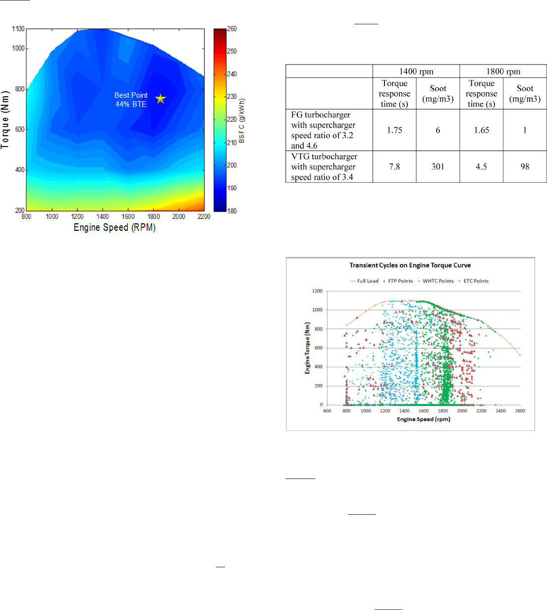
Figure 4 shows BSFC map of API’s 4.9 L research engine from these
steady state measured results.
Figure 4. BSFC map from steady state measured data on API research engine.
TRANSIENT CONTROLS AND TEST RESULTS
Compared to the controls software for steady state calibration, the
transient operation of the engine need strategy for limiting smoke
during acceleration; and for faster actuator response for driving air
and EGR. The 4.9L research engine controls strategy was improved
with a smoke limiter algorithm and feed-forward controllers for air
and EGR actuators.
The smoke limiter algorithm essentially is limiting the amount of fuel
that can be injected in the cylinder during acceleration as the air
handling devices (turbocharger and supercharger) respond slower
than the fuel system. Rail pressure modier was also implemented for
increasing rail pressure during transient.
For increasing airow during acceleration, EGR valve is closed to
allow for more massow through turbine for reducing turbo lag. For
supercharger, rst the recirculation valve is closed; if the airow
demand is still not met (or in conditions where the recirculation valve
is already fully closed for the starting point), the supercharger
2-speed drive is switched to higher drive ratio. With smoke limiter
implemented and higher supercharger drive ratio, the engine was able
to achieve the full load torque from 25% load at constant speed
within 1.5 seconds with minimal NOx and soot spikes. The torque
response time and emissions results for different supercharger drive
ratios for OP engine have been discussed in detailed earlier [13].
The 4.9 L research engine was also investigated for transient response
with Variable Turbine Geometry (VTG) turbocharger and single gear
ratio supercharger. A comparison of VTG turbo with single drive
supercharger and xed geometry turbo with 2-speed supercharger for
transient response for 1 second torque ramps at two different engine
speeds is shown in table 4 below.
Table 4. Transient response comparison of VTG turbocharger and single speed
supercharger Vs FG turbocharger and 2-speed supercharger.
As seen from the results, the supercharger 2-speed drive is improving
the transient response of the OP 2-stroke engine signicantly. With
developed transient controls, the 4.9 L research engine was put on
test for transient emissions cycle.
Figure 5. US heavy-duty FTP together with European ETC and WHTC cycles
operating points on API 4.9L research engine torque curve.
Figure 5 shows engine operating conditions for three transient cycles
- US heavy duty FTP, WHTC and ETC plotted with the torque curve.
As seen from the gure 5, the ETC cycle operates heavily around
1800 rpm for API 4.9L engine (on the higher engine speed region
similar to ESC cycle), while the WHTC cycle is weighted more in the
region of 1500 rpm (relatively lower engine speed region similar to
WHSC cycle). Though the engine operates more in the speed range
of 1700 to 2200 rpm for the heavy duty FTP cycle for US 2010
emissions, this transient cycle has wider speed range and larger speed
gradients. Also, it is designed for both city as well as highway driving
conditions as seen in the gure 6 with New-York Non-Freeway
(NYNF), Los Angeles Non-Freeway (LANF) and Los Angeles
Freeway (LAFY) segments. Therefore heavy duty FTP was selected
for testing transient capabilities of the 4.9 L research engine.
Naik et al / SAE Int. J. Engines / Volume 10, Issue 1 (February 2017)
20
Downloaded from SAE International by Suramya Naik, Thursday, July 06, 2017

Figure 6. US heavy-duty FTP cycle with NYNF, LANF and LAFY segments [16].
During the transient testing, engine speed, torque and power
requirements were appropriately matched with the targets to meet the
heavy duty FTP cycle requirements. Statistically, the R
2
values of the
measured speed, torque and power compared to the targets were 0.97,
0.94 and 0.98 respectively - within the range specied by the
regulations. The heavy duty transient cycle averaged values of BSFC,
BSNOx and BSSoot were measured to be 217.3 g/kWh, 4.3 g/kWh and
0.056 g/kWh respectively. When compared with the BSFC map data
generated from the steady state measurements, the transient BSFC is
only 2.1 g/kWh higher - suggesting that the controls strategies are
working decently as required for such application. Detailed description
and results of the US 2010 heavy duty transient test for API’s 4.9L
engine have been published in 2016 SAE paper [11].
Additional to transient controls, API has also developed warm-up
strategies for catalyst light off, details of which have been published
in other papers [10][13].
CONFIRMING TAILPIPE EMISSIONS
API teamed up with Johnson Matthey - a leading after-treatment
supplier to check if the tailpipe emissions of its 4.9L OP engine meet
stringent BSVI standards. Johnson Matthey has developed a patented
SCRT
®
aftertreatment system (ATS) which allows for passive
regeneration of particulate lter using higher engine out NOx, and
SCR to reduce the NOx [12].
The system has DOC with platinum group metals (PGM) as rst
component to oxidize HC and CO, also to convert NO to NO
2
that
helps with passive regen of particulate lter. Second component is
Catalyst Soot Filter (CSF) for removing PM. Urea is injected after
CSF and before SCR to remove NOx emissions. And nally, ASC is
used to oxidize access NH
3
. Figure 7 shows schematic of Johnson
Matthey’s patented SCRT
®
aftertreatment system.
Figure 7. Johnson Matthey’s SCRT
®
aftertreatment system [12].
This system was sized for reasonable space velocities through its
components and simulated with chemistry models by Johnson
Matthey engineers to check its performance for 13 mode steady state
engine out exhaust from API’s 4.9L research engine. Full details of
the study have been published in 2016 emissions conference paper
[12]. The details of the various ATS components size and structure
are shown below in gure 8.
Figure 8. Simulated ATS components volume, CPSI/wall thickness and PGM
loading [12].
To check for possibilities of passive regeneration of CSF, the DOC
was simulated for two cases -
Case 1. Low Pt:Pd (2:1) ratio aged at 780
0
C/10h and
Case 2. High Pt:Pd (5:1) ratio aged at 780
0
C/100h [12].
The 100 repetitions of 13 mode steady state cycle results show that
for case 2, the DOC would remove THC and CO 92 and 100%
respectively [12]. CSF would go through sufcient passive
regeneration to stabilize at 1.3 g/L soot loading after 100 ESC tests
[12]. The NOx conversion efciency of 96% can be achieved with
the SCR [12]. The maximum pressure drop through this ATS for the
steady state cycle simulations is 15 kPa for 0 g/l soot in CSF and 16.5
kPa for 3 g/l soot loading in CSF. Table 5 below show cycle averaged
tailpipe emissions for 13 points of the ESC test [12].
Naik et al / SAE Int. J. Engines / Volume 10, Issue 1 (February 2017)
21
Downloaded from SAE International by Suramya Naik, Thursday, July 06, 2017

Table 5. Summary of Johnson Matthey ATS simulation results on API’s 4.9L
engine out cycle-averaged emissions for 13 points of ESC cycle [12].
Results of steady state cycles operating points listed in Appendix A
show that the turbine out temperatures of the exhaust for all of the
WHSC points except idle range between 250 to 368
0
C which is
similar to the range of 236 to 357
0
C seen on the ESC cycle points.
Therefore, even though the aftertreatment simulations were carried
out on 100 cycles of the 13-modes of ESC test, simulating the WHSC
operating points with after-treatment should also be able to meet the
tailpipe emissions targets.
The same aftertreatment system was also simulated by Johnson
Matthey engineers for heavy-duty transient FTP cycle data measured
on 4.9 L research engine. Figure 9 below show space velocities
through different ATS components and inlet temperature for the
heavy-duty FTP cycle.
Figure 9. Space velocities through different ATS components and inlet
temperature for the heavy-duty FTP cycle.
As seen from gure 9, the ATS inlet gas temperature varies between
160 to 300
0
C. The maximum pressure drop of the entire ATS for the
heavy-duty FTP cycle simulation was 10.4 kPa for 0 g/l soot
loading and 12.1 kPa for 3 g/l soot loading. Table 6 below show
emissions conversion efciencies achieved during the heavy-duty
FTP cycle simulations.
Table 6. Summary of Johnson Matthey aftertreatment system simulation
results on API’s 4.9L engine out exhaust for heavy-duty FTP transient cycle.
These ATS system simulations for steady state and transient cycles
with measured engine out emissions and exhaust temperatures
conrm that API’s 4.9 L engine will meet BSVI tailpipe emissions.
COMPARISON WITH 4-STROKE DIESEL
ENGINE
The data published in this paper so far is with API’s 4.9 L research
engine that has high friction penalties as seen in the data table in
Appendix A. When the design is optimized for production, API’s 4.9 L
year 2020 engine has been predicted to achieve best BTE of 48.5% and
ESC 12 mode cycle average BTE of 46.6% (180 g/kWh cycle averaged
BSFC) [9] while meeting US 2010 emissions (comparable to BSVI
emissions standards). These data can be compared with 6.7 L Ford
Power-stroke V8 engine [14] and 6.7 L inline 6 Cummins ISB engine
(data published in one report by the International Council of Clean
Transportation (ICCT) [15] and in another by SouthWest Research
Institute (SWRI) [17]). Table 7 below shows comparison of API’s 4.9L
OP engine with Ford Power-stroke and Cummins ISB specications.
Table 7. Specifications of comparable 2-stroke OP and 4-stroke engines
meeting US 2010 emissions standards (comparable to BSVI) .
The SAE paper with Ford Power-stroke [14] and SWRI report [17]
have full steady state BSFC data allowing comparison for steady state
cycles. The SWRI report has also predicted the BSFC of improved
Cummins ISB engine in year 2019 with reduced friction, improved
turbocharger and reduced combustion duration [17]. This data can be
compared with API’s 4.9L production engine for 2020.
Figure 10 show comparison between various medium duty
application engines that meet US 2010 emissions - which are similar
to BSVI emissions standards. As seen from the gure 10, API’s 4.9 L
research engine measured data show 20.7% and 10.7% fuel economy
advantage over 2010 Ford Power-stroke and 2012 Cummins ISB
engines respectively when compared for 12 operating modes of the
ESC cycle excluding idle. With at fuel map for API’s OP engine [8]
[9], higher available torque at lower speeds and improved part load
fuel economy over 4-stroke engines, the vehicle fuel economy
advantage of OP engine in real world driving can be signicantly
Naik et al / SAE Int. J. Engines / Volume 10, Issue 1 (February 2017)
22
Downloaded from SAE International by Suramya Naik, Thursday, July 06, 2017

higher. When API’s production 4.9L engine predicted performance is
compared with 2019 Cummins ISB predicted by SWRI [17], the OP
engine show 16.2% fuel economy advantage.
Figure 10. 12 mode cycle averaged BTE results comparison shown together
with % improvement with API’s OP engines.
The ICCT has published transient heavy duty FTP data for Cummins
ISB (year 2011) with calibration that allows for slightly higher torque
(1016 Nm) and power (242.5 kW) [15]. The table below show
comparison of measured heavy-duty FTP cycle averaged data on
API’s 4.9L research engine with Cummins ISB MY 2011.
Table 8. Hot start heavy duty FTP cycle results comparison between API’s OP
engine and Cummins ISB.
As seen from table 8, API’s 4.9L OP engine measured data is showing
21.9% fuel economy improvement over Cummins ISB for the
heavy-duty FTP cycle. This is substantially higher than 10.7%
improvement seen from comparing the steady state data in gure 10.
This dataset proves that the at BSFC map of OP engine helps
improve the real world fuel economy almost twice compared to what
can be calculated from steady state BSFC map comparison.
SUMMARY
Opposed piston engines have signicant fuel economy advantage and
potential for lower cost over 4-stroke conventional engines. Achates
Power Inc. has pioneered OP engine technology and shown with
measured data on its 4.9L research engine that -
• API has successfully developed and implemented controls
strategies for the engine to run it effectively on steady state and
transient emission cycles.
• When simulated with Johnson Matthey sized conventional
diesel after-treatment system, API’s OP engine can meet Bharat
Stage VI tailpipe emissions standards.
• API’s current 4.9L research engine is showing 10 to 21% fuel
economy improvement over comparable conventional medium-
duty 4-stroke engine. This fuel economy advantage is expected to
increase with API’s lower friction optimized production engine.
Thus, Opposed Piston engines are capable to address the challenges
faced by Indian OEMs to meet Bharat Stage VI emissions standards
with reduced cost and offer improved fuel economy to the end users.
REFERENCES
1. Heavy-Duty emissions standards for India; Retrieved from Dieselnet
weblink- https://www.dieselnet.com/standards/in/hd.php.
2. Sanchez, F., Bandivadekar, A., German, J., “Estimated Cost of
Emissions Reduction Technologies for Light-Duty Vehicles”, The
International Council on Clean Transportation, 2002. http://www.theicct.
org/sites/default/files/publications/ICCT_LDVcostsreport_2012.pdf
3. Posada, F., Chambliss, S., and Blumberg, K., “Costs of Emissions
Reduction Technologies for Heavy-Duty Vehicles”, The International
Council on Clean Transportation, 2016. http://www.theicct.org/
sites/default/files/publications/ICCT_costs-emission-reduction-tech-
HDV_20160229.pdf
4. Kromer, M., Bockholt, W., Jackson, M., “Assessment of Fuel-Economy
Technologies for Medium - and Heavy-Duty Vehicles”, TIAX LLC.,
Final report to National Academy of Sciences, 2009.
5. Flint, M. and Pirault, J.P., “Opposed Piston Engines: Evolution, Use, and
Future Applications”, SAE International, Warrendale, PA ISBN 978-0-
7680-1800-4, 2009.
6. Warey, A., Gopalakrishnan, V., Potter, M., Mattarelli, E. et al.,
"An Analytical Assessment of the CO
2
Emissions Benefit of Two-
Stroke Diesel Engines," SAE Technical Paper 2016-01-0659, 2016,
doi:10.4271/2016-01-0659.
7. Herold, R., Wahl, M., Regner, G., Lemke, J., and Foster, D.,
“Thermodynamic Benefits of Opposed-Piston Two-Stroke Engines,”
SAE Technical Paper 2011-01-2216, 2011, doi: 10.4271/2011-01-2216.
8. Naik, S., Johnson, D., Fromm, L., Koszewnik, J. et al., "Practical
Applications of Opposed-Piston Engine Technology to Reduce Fuel
Consumption and Emissions," SAE Technical Paper 2013-01-2754.
9. Naik, S., Redon, F., Regner, G., and Koszewnik, J., "Opposed-Piston
2-Stroke Multi-Cylinder Engine Dynamometer Demonstration," SAE
Technical Paper 2015-26-0038, 2015, doi:10.4271/2015-26-0038.
10. Redon, F., Kalebjian, C., Kessler, J., Rakovec, N. et al., "Meeting
Stringent 2025 Emissions and Fuel Efficiency Regulations with an
Opposed-Piston, Light-Duty Diesel Engine," SAE Technical Paper
2014-01-1187, 2014, doi:10.4271/2014-01-1187.
11. Sharma, A., Redon, F., “Multi-Cylinder Opposed-Piston Engine
Results on Transient Test Cycle,” SAE Technical Paper 2016-01-1019,
doi:10.4271/2016-01-1019.
12. Nagar, N., Sharma, A., Redon, F., “Simulation and Analysis of After-
Treatment Systems (ATS) for Opposed-Piston 2 stroke Engine,”
Emissions 2016 Conference.
13. Redon, F., Sharma, A., and Headley, J.,”Multi-Cylinder Opposed Piston
Transient and Exhaust Temperature Management Test Results,” SAE
Technical Paper 2015-01-1251, doi:10.4271/2015-01-1251.
14. DeRaad, S., Fulton, B., Gryglak, A., Hallgren, B., Hudson, A., Ives, D.,
Morgan, P., Styron, J., Waszczenko, E., Cattermole, I., “The New Ford
6.7L V-8 Turbocharged Diesel Engine”, SAE International Technical
Paper 2010-01-1101, 2012.
15. Thiruvengadam, A., Pradhan, S., Thiruvengadam, P., Besch, M., Carder,
D., Delgado, O., “Heavy-Duty Vehicle Diesel Engine Efficiency and
Energy Audit”, http://www.theicct.org/heavy-duty-vehicle-diesel-engine-
efficiency-evaluation-and-energy-audit ,10/12/2014.
16. Heavy-Duty FTP Transient Cycle retrieved from Dieselnet weblink -
https://www.dieselnet.com/standards/cycles/ftp_trans.php
Naik et al / SAE Int. J. Engines / Volume 10, Issue 1 (February 2017)
23
Downloaded from SAE International by Suramya Naik, Thursday, July 06, 2017

17. Reinhart, T. E., “Commercial medium- and heavy-duty truck fuel
efficiency technology study - Report #2’ (Report No. DOT HS 812 194).
National Highway Traffic Safety Administration. http://www.nhtsa.gov/
Laws-&-Regulations/
CONTACT INFORMATION
Suramya Naik
Chief Engineer and Program Manager
Achates Power, Inc.
naik@achatespower.com
ACKNOWLEDGMENTS
We acknowledge and thank Johnson Matthey for carrying out
after-treatment sizing and simulation activities and for allowing us to
publish the results.
DEFINITIONS/ABBREVIATIONS
API - Achates Power Inc.
OP - Opposed-Piston.
BSFC - Brake Specic Fuel Consumption
BSNOx - Brake Specic Nitrogen Oxides
BSHC - Brake Specic Hydrocarbons
BSCO - Brake Specic Carbon Monoxide
PM - Particulate Matter
THC - Total Hydrocarbon
ESC - European Steady-state Cycle
ETC - European Transient Cycle
WHSC - World Harmonized Steady-state Cycle
WHTC - World Harmonized Transient Cycle
BTE - Brake Thermal Efciency
VTG - Variable Turbine Geometry
ATS - After-treatment System
DOC - Diesel Oxidation Catalyst
DPF - Diesel Particulate Filter
SCR - Selective Catalyst Reduction
ASC - Ammonia Slip Catalyst
CSF - Catalyst Soot Filter
PGM - Platinum Group Metals
CPSI - Cells per square inch
Naik et al / SAE Int. J. Engines / Volume 10, Issue 1 (February 2017)
24
Downloaded from SAE International by Suramya Naik, Thursday, July 06, 2017

APPENDIX
Appendix A: Measured steady state data on API’s 4.9L OP 2-Stroke research engine
ESC Cycle
Naik et al / SAE Int. J. Engines / Volume 10, Issue 1 (February 2017)
25
Downloaded from SAE International by Suramya Naik, Thursday, July 06, 2017

WHSC Cycle
All rights reserved. No part of this publication may be reproduced, stored in a retrieval system, or transmitted, in any form or by any means, electronic, mechanical, photocopying, recording, or
otherwise, without the prior written permission of SAE International.
Positions and opinions advanced in this paper are those of the author(s) and not necessarily those of SAE International. The author is solely responsible for the content of the paper.
Naik et al / SAE Int. J. Engines / Volume 10, Issue 1 (February 2017)
26
Downloaded from SAE International by Suramya Naik, Thursday, July 06, 2017
