
Copyright © 2017 Water Environment Federation. All Rights Reserved.
WSEC-2017-TR-002, RBC Bioenergy Technology Subcommittee, CHP Task Force 1
INTERNAL
COMBUSTION
ENGINES
Combined Heat and Power

Copyright © 2017 Water Environment Federation. All Rights Reserved.
WSEC-2017-TR-002, RBC Bioenergy Technology Subcommittee, CHP Task Force 2
Acknowledgments
Principal Authors
Matthew T. Goss, P.E., CEM, CEA, CDSM, LEED® AP (BD+C), CDM Smith
Glynn MacKenzie, P.E. Mechanical Engineer
Jason Wiser, P.E. Brown and Caldwell
Patrick Wootton, Business Development Manager, Nixon Energy Solutions
Myron Bachman, Plant Superintendent, North Davis Sewer District
Final Reviewers
Kevin R Cowan P.E., District Manager, North Davis Sewer District
Tom Phelps, Principal, Stantec
David Wrightsman, PE, Business Development Manager, Energy Systems Group
Water Environment Federation Residuals and Biosolids Committee,
Bioenergy Technology Subcommittee
Dru Whitlock, P.E., Vice President, Environmental Engineer, CDM Smith (Subcommittee Chair)
Jeffrey Layne, P.E., HRSD (Subcommittee Vice Chair)

Copyright © 2017 Water Environment Federation. All Rights Reserved.
WSEC-2017-TR-002, RBC Bioenergy Technology Subcommittee, CHP Task Force 3
Table of Contents
Acknowledgments .............................................................................................................................................................. 2
Table of Contents ................................................................................................................................................................ 3
Executive Summary ............................................................................................................................................................. 4
Combined Heat & Power................................................................................................................................................... 6
Introduction .......................................................................................................................................................................... 6
Fundamentals ....................................................................................................................................................................... 7
Fundamentals & Summary ................................................................................................................................................. 8
Characteristics / Applicability ........................................................................................................................................... 9
Gas Treatment and Appurtenances ............................................................................................................................. 10
Hydrogen Sulfide ................................................................................................................................................................ 10
Siloxanes .............................................................................................................................................................................. 11
Moisture ............................................................................................................................................................................... 13
Fuel Pressurization .............................................................................................................................................................. 13
Fuel Blending ...................................................................................................................................................................... 13
Support Systems & Temperature Control ...................................................................................................................... 15
Heat Recovery ................................................................................................................................................................... 15
Internal Combustion Engine Operations ....................................................................................................................... 17
Case Study 1 ....................................................................................................................................................................... 19
Technical Specifications of Facility ................................................................................................................................ 19
Case Study 2 ....................................................................................................................................................................... 20
Digester Gas Treatment .................................................................................................................................................... 20
Power Generation .............................................................................................................................................................. 20
Heat Recovery .................................................................................................................................................................... 20
Operation and Maintenance .......................................................................................................................................... 21
Special Considerations ..................................................................................................................................................... 21
Gas-Fueled Internal Combustion Engine Criticalities .................................................................................................. 21
Support System Requirements ......................................................................................................................................... 21
Engine Container Solutions .............................................................................................................................................. 22
Rules of Thumb/Considerations ...................................................................................................................................... 22
Additional Resources ........................................................................................................................................................ 24

Copyright © 2017 Water Environment Federation. All Rights Reserved.
WSEC-2017-TR-002, RBC Bioenergy Technology Subcommittee, CHP Task Force 4
Executive Summary
COMBINED HEAT AND POWER
INTERNAL COMBUSTION ENGINE TECHNOLOGY
Reciprocating Internal combustion engine (ICE) technology has been around since the 19
th
century. There
are other types of combined heat and power technologies (CHP) in use at water resource recovery facilities, such
as gas turbines, micro-turbines, and fuel cells. However, as of 2011, 50% of the U.S. water resource recovery
facilities sites with CHP use ICE technology (US EPA Combined Heat & Power Partnership (2011)
Opportunities for Combined Heat and Power at Wastewater Treatment Facilities, Web,
https://www.epa.gov/chp/opportunities-combined-heat-and-power-wastewater-treatment-facilities-market-analysis-and).
CHP is the simultaneous generation of electricity (power), and useful heat (thermal energy) using fuel
energy supplied to the engine-generator ICE technology is an economical option
for
engine-generator
sizes from 200 kW through 2,000 kW, with unit sizes up to 9,000 kW available. There are more than 50 sites
within the US water resource recovery industry demonstrating this reliable technology and
its economic
benefits. In addition, the US Department of Energy (DOE) has been supporting the ARES
(Advanced
Reciprocating Engine Systems) program to develop higher efficiency, lower cost CHP engine
solutions.
ARES has helped produce ICEs with emissions reduced to 0.5
grams/brake horsepower hour of oxides of
nitrogen (NOx), and 2.5 grams/brake horsepower hour of carbon monoxide (CO). These lower emission
limits
allow the ICE technology to meet some of the more stringent emissions required in many jurisdictions.
One of the most important considerations in choosing ICE technology is proper sizing, to match both the
facility’s ‘steady’ electrical load and the available fuel (digester gas). Because ICE CHP systems are
capital-intensive, oversizing the equipment usually results in poor economics due to higher fixed costs and
the associated lower equipment load factor.
Care
also must be used to provide the appropriate fuel treatment system to meet the ICE manufacturer’s
requirements
. Hydrogen sulfide (H
2
S), siloxanes, and water condensation are common digester gas contaminants
which ICEs do not tolerate well, so gas conditioning to remove these is typical to most installations. The degree of
contaminant removal required varies with the digester gas composition and with the specific ICE manufacturer’s
requirements. In some instances, plant owner/operators may decide to reduce or eliminate some gas conditioning
equipment to reduce initial cost, expecting more frequent engine servicing, higher repair costs, and reduced reliability
as a result. However, operating outside the manufacturer’s fuel contaminant limits is likely to adversely affect the
equipment warranty coverage.
Most ICE generators can run on either digester gas, natural gas, or a mixture of the
two. However, it may not be possible to switch between fuels without an engine shut-down, and fuel blending can
be cumbersome. However, because digester gas production rates often vary considerably, providing natural gas as
a supplemental or standby fuel is common. Storage is another way to improve digester gas utilization while better
matching the generator electrical loads.
In addition to
proper fuel treatment ICE generators using primarily digester gas fuel require more
maintenance compared to diesel or natural gas fueled engines. Consequently, engine service contracts
with the engine manufacturer are commonly used. These contracts can cover all routine servicing as
well as major repairs, or routine servicing can be performed by the owner-operator. Remote engine
monitoring is typical and is often required by the manufacturer as a condition of the equipment
warranty.

Copyright © 2017 Water Environment Federation. All Rights Reserved.
WSEC-2017-TR-002, RBC Bioenergy Technology Subcommittee, CHP Task Force 5
ICE generators can operate in several different modes to provide electricity to the water treatment facility
and, in some cases, to the electric utility grid. Options include ‘base load’, ‘peak shaving’, and ‘island’
modes, where all generated power is consumed ‘behind the meter’ by the water treatment facility. Island
mode means that the ICE equipment is isolated from the electric utility and serves specific on-site loads. In
island mode, an ICE CHP system can provide emergency power for some portions of the plant. ‘Base
load’ and ‘peak shaving’ are usually most effective when operating in parallel with the electric utility.
However, electric utility interconnection requirements may make parallel operation impractical. In some
cases, the ‘renewable power’ generated can be sold to the electric utility grid at a premium price,
though this is rarely the most cost-effective approach, due to low export prices most electric utilities offer.
Typically, one third of the total energy cost savings from CHP systems is due to the ‘free’ useful heat
produced as a byproduct of power generation, with power cost savings being the remainder. To ensure
that potential heating savings are realized in practice, CHP heat recovery systems and controls must be
closely integrated with the existing plant heating systems. Providing heat to the anaerobic digesters is
usually more important than space heat because the digester heating loads are more continuous
throughout the year and better match generator operating hours.
CHP systems using ICE technology are commonly available in factory-assembled, modular, weather-proof
enclosures. Many manufacturers provide modular CHP systems with unit ratings up to 2,000 kW, and some
provide larger systems. Modular construction simplifies field installation work, and may save on first cost
when no interior space is otherwise available for the equipment. Reduced equipment access for servicing,
especially for major repairs, is one drawback. For example, if you have to remove the engine from the
container to change the heads it can prove to be a costly O&M challenge. Some containers offer fully
removable sides solving this problem.

Copyright © 2017 Water Environment Federation. All Rights Reserved.
WSEC-2017-TR-002, RBC Bioenergy Technology Subcommittee, CHP Task Force 6
Combined Heat & Power
Introduction
This document provides a status review of combined heat & power (CHP) technologies applicable for
implementation at water resource recovery facilities. Combined Heat & Power (CHP), also called
‘cogeneration’, is defined as the concurrent or simultaneous production of electricity and thermal energy
from a power generating device. Reciprocating Internal Combustion Engines (ICE) provide nearly 2.3 GW
of power capacity in CHP installations. This report describes the technology, theory, and operation of such
facilities, as well as providing technical data from available manufacturers.
The original ICE was created in 1859 as a means of converting chemical energy (fuel), typically in the form
of gasoline or diesel, into mechanical energy. As the fuel is burned in the combustion chamber in the
presence of high pressure air, a controlled explosion results in a force that drives the piston (or in the case of
a gas turbine, the turbine blades) creating mechanical energy.
Technological improvements have increased the ICE’s efficiency, largely by decreasing frictional losses in
moving parts and improving the precision timing in the combustion process, where the air/fuel mixture is
drawn into the chamber before being compressed, ignited, and exhausted (Figure 1). In addition, ICEs
remain a common power source in the 21st century because of their adaptability, whether in the form of a
reciprocating piston engine for automobiles and ships, or stationary applications in power plants where the
engine’s mechanical energy is converted to electrical energy through a generator.
Figure 1: The Four Stages of Combustion in a Four Stroke Reciprocating Engine
(Source: Urone, Paul Peter, and Roger Hinrichs. "College Physics." Chapter 15, Thermodynamics, p. 587;
OpenStax. Creative Commons Attribution License V4.0, 21 June 2012. Web. 06 July 2017.)
Copyright © 2017 Water Environment Federation. All Rights Reserved.
WSEC-2017-TR-002, RBC Bioenergy Technology Subcommittee, CHP Task Force 7
Fundamentals
Although the majority of ICE’s are used for transportation purposes in motor vehicles, this document is
focused on stationary engine/generator applications for power production. Internal combustion engines
and heat recovery methods are the cornerstones of Combined Heat and Power systems at all scales. For
universities, hospitals, data centers, and municipal utilities, ICE technology is the most common way to
provide standby power should the electric utility fail. At some sites, adding heat recovery to create a CHP
system allows the facility to provide its own power more economically that purchasing power from the grid.
The combustion process for reciprocating engines can vary widely stemming from the various manufactures
trying to match their engines to the specific needs of various customers. Applications like lawnmowers and
outboard motors require less precision and reliability, and many of those use simpler two-stroke engines.
Reciprocating engines with high power to weight ratios were preferred for use on World War II era aircraft
before being replaced by jet engines and turboprops in 1944. The higher electrical efficiency of these
reciprocating engine-generators, as well as their operational flexibility in ramping up and down for load
matching, led to their use in over 2,000 CHP facilities throughout the United States.
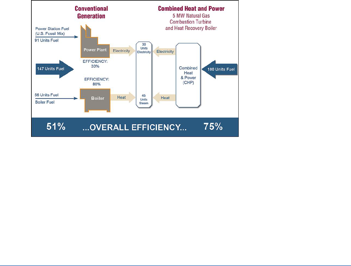
Figure 2: CHP vs. Conventional Generation
(Source: USEPA, Combined Heat and Power Partnership (2015) "Fuel and Carbon Dioxide Emissions Savings Calculation Methodology
for Combined Heat and Power Systems," Feb. 2015, p. 5. Web., https://www.epa.gov/sites/production/files/2015-
07/documents/fuel_and_carbon_dioxide_emissions_savings_calculation_methodology_for_combined_heat_and_power_systems.pdf)
The central theme of CHP applications is converting chemical energy from fuel into both electrical and
thermal energy. Shown in Figure 2, this simultaneous production of energy in two forms typically increases
overall efficiency from 45 percent to around 70 percent or more. Of paramount importance, however, is
matching the CHP capacity to the facility simultaneous thermal and electrical demand, because
recovered heat energy can only improve the efficiency if it is properly utilized. For example, a facility with
constant electrical and thermal demands of one megawatt electrical demand and three million BTU/hr
heat demand respectively, would be a great fit for CHP. However, should the one megawatt electrical and
three million BTU/hr heat load not coincide, the facility will lose the benefit of simultaneous production.
Therefore, load matching and its seasonal fluctuations play a large role in assessing the ‘real world’
economic viability of a CHP plant.
The potential for efficiency improvements has received a renewed focus in recent years, as a result of rising
costs of energy, environmental concerns over reducing fossil fuel use, and emissions impacts. CHP presents
an economical existing technology to meet the country's rising energy demands without fundamentally

Copyright © 2017 Water Environment Federation. All Rights Reserved.
WSEC-2017-TR-002, RBC Bioenergy Technology Subcommittee, CHP Task Force 8
changing the infrastructure. This renewed focus is driving the US Department of Energy's effort to provide 20
percent of all electric generation through CHP by 2030, up from 8% in 1978 (U.S. Department of Energy,
Powering Progress in Combined Heat and Power (CHP) (2008) Web.,
https://www1.eere.energy.gov/manufacturing/distributedenergy/pdfs/itp_chp.pdf).
Fundamentals & Summary
While all reciprocating internal combustion engines units use the same basic operating principles, there are
various technology differentiators. Specifically, for “spark ignition” reciprocating internal combustion
engines, there are:
High Speed
(1000-3600 rpm)
Medium Speed
(275-1000 rpm)
Rich Burn
0.01 – 1.5 MW
Lean Burn
0.15 – 3.0 MW
1.0 – 18 MW
Source: Data from U.S. EPA
Technological improvements since the development of the first ICEs have enhanced the
combustion
control systems, resulting in increased efficiencies and reduced emissions. While rich
burn engines operate
at a near stoichiometric air to fuel ratio (AFR), lean burn engines essentially
flood the combustion chamber
with air, nearly doubling the amount of air for fuel combustion. The
more diluted mixture reduces peak
combustion temperatures, reducing oxides of nitrogen (NOx)
emissions which are primary contributors to the formation of
ozone and other health problems. The
lean burn engine's lower NOx levels, at five to ten percent of the rich burn
engine's, provide the
highest possible efficiency level for moderate emissions limits of 250-500 mg/Nm
3
NOx
(at 5 percent
O
2
in the exhaust gas).
However, when more stringent emissions limits are required, as in most of the Northeast United States,
both
lean burn engines and rich burn engines require exhaust gas treatment through a catalyst. The
rich burn
engine's near stoichiometric exhaust gas composition and high combustion temperatures
allow the use of a
simple three way catalyst, similar to those utilized in automobile exhaust systems, to
reduce NOx, Carbon
Monoxide, hydrocarbons, and other harmful air pollutants. Unfortunately, the
simple three-way catalyst
used in rich burn engines requires clean fuels like natural gas. Biogas,
digester gas, and landfill gases cannot
be used due to their potential for "poisoning" the catalyst.
The lean burn engine, on the other hand, requires selective catalytic converters with Urea
(Ammonia) injection, which adds expense and other
toxicity and exposure concerns when stored in
large quantities on site.
The US Department of Energy (DOE) has been supporting the ARES (Advanced Reciprocating
Engine
Systems) program to develop higher efficiency, lower cost CHP engine solutions. Through this
program engine efficiency (without heat recovery) has been increased to as high as 43.5%.

Copyright © 2017 Water Environment Federation. All Rights Reserved.
WSEC-2017-TR-002, RBC Bioenergy Technology Subcommittee, CHP Task Force 9
Characteristics / Applicability
When considering the potential for employing gas-fueled reciprocating engines to operate on
digester gas, there
are a significant number of available manufacturers of reliable equipment.
The process of combusting digester gas for the
purposes of combined heat and power (CHP) has
been executed successfully at a large number of
facilities both globally and within the United
States. Numerous manufacturers of gas reciprocating engines
have demonstrated product
competence in this arena. This section of the paper discusses these proven
manufacturers, engine
performance, and emission performance as they apply to operations on digester gas.
Several years ago, the gas reciprocating engine market experienced a consolidation in
competing brands
offered. General Electric (GE), the owner of Jenbacher gas engines,
purchased Waukesha gas engines,
and Caterpillar, at about the same time, purchased the
MWM gas engine brand. While Cummins also
offered high quality engines. This market
consolidation may have seemed to reduce the competitive
nature and technological
advancement of the engine market, but the acquired brands are still offered in the market
through their new parent companies. All three gas engine
manufacturers, Caterpillar, Cummins,
and GE have continued to invest in their product offerings. Additionally, reputable European gas
reciprocating engine manufacturers such as MTU, Siemens (who acquired Dresser and Guascor)
Liebherr, and MAN have entered the US market for digester gas applications.
When evaluating the potential for generating electrical energy from digester gas, the first
consideration for
the project owner is to match the size of the reciprocating engine to the process
flows and electrical loads. Gas reciprocating engines
range in size from 140 kW
el
to over 9,000
kW
el
. A rough rule of thumb is that a 10-MGD average flow plant would
produce enough
digester gas to power 330 kW
el
, while a 25-30 MGD average flow plant would produce
enough
gas to generate up to about 1,000 kW
el
. It is a rare occasion that a digester gas facility would not
be able to find an ICE generator size that could efficiently accommodate its gas production rate.
Performance of gas engines is based upon the efficiency of the engine in converting chemical
energy from
the digester gas to electricity and heat. Gas reciprocating engines consist of an
alternator (electrical power generator) and an engine
component. The engine component
combusts the digester gas thereby producing mechanical energy. This mechanical energy is then
converted to electricity by the alternator. Heat is recovered from the engine component as a
byproduct of power generation. In the recent past significant improvements in power generation
efficiency have been achieved by most of the ICE manufacturers. Programs, such as the
Advanced Reciprocating Engine System (ARES) funded by the United States Department of
Energy, have
supported these technological advancements. In the case of the ARES program
specifically, it produced
improvements to American manufactured gas engines and responses in
kind from European and other
manufacturers. Overall engine performance is rated on electrical
efficiency, thermal efficiency, and
overall combined efficiency (a summation of thermal and
electrical efficiency). A typical range of fuel-to-electrical power efficiencies is from 35% to 45%
based upon the Lower Heating Value (LHV) of the digester gas. Thermal efficiency is a measure of
the heat recovered from the engine during combustion compared to
the energy input of the
digester gas. Typical thermal efficiencies range from 40% to 50%. As a rule of
thumb, gas
reciprocating engine’s heat is recovered from the engine lube oil, engine jacket water, engine
intercooler, and exhaust. Approximately half of the heat is high temperature heat (700
o
F – 950
o
F)
recovered from the exhaust with the remainder recovered from the lower grade temperature
elements
made up by the combined lube oil, jacket water, and intercooler, (180
o
F – 230
o
F).
Finally, the total
efficiency of a CHP system is the summation of the electrical and thermal

Copyright © 2017 Water Environment Federation. All Rights Reserved.
WSEC-2017-TR-002, RBC Bioenergy Technology Subcommittee, CHP Task Force 10
efficiencies of the engine. Total
engine efficiency ranges from 75% to 90%. The more electrically
efficient engines have lower thermal
performance whereas higher thermally performing engines
have a lower electrical efficiency.
The future for digester gas-fueled CHP projects using gas reciprocating engines will likely see
greater
importance placed on engine emissions. Currently, the two most significant emissions in
terms of air
permitting are NO
x
and CO. Either of these emissions, or both, can be limiting factors
when permitting gas
engines. It is common for engine manufacturers to set their engine emissions
performance based upon NOx output. The most efficient engines will emit NOx in a range of 0.5 –
0.6 g NOx/bhp-hr. In locations
where less stringent NO
x
standards exist, manufacturers provide a
1.0 – 1.1 g NO
x
/bhp-hr. The typical range
for CO emissions is 2.5 - 3.0 g CO/bhp-hr. Additional
emissions performance requirements such as
formaldehydes, VOC, and SO
x,
may also be
included in the air quality permit in certain locations. Engine
emission ratings for all parameters
often depend upon the condition and relative cleanliness of the digester
gas.
Gas Treatment and Appurtenances
Digester gas contains impurities that can shorten the life and degrade performance of all types of
CHP
prime movers, including internal combustion engines. Therefore, fuel pretreatment is required
for nearly all
digester-gas-fueled CHP applications. Hydrogen sulfide (H
2
S), liquid moisture, and
siloxanes are of particular concern and
should be controlled to meet the CHP system’s prime
mover fuel specifications.
Hydrogen Sulfide
Hydrogen sulfide, (H
2
S), is oxidized during combustion leading to the formation of acidic sulfur
dioxide, (SO
2
)
which can be extremely corrosive to internal combustion engine components. High
H
2
S concentrations in
digester gas can turn engine and compressor oil acidic, resulting in more
frequent oil changes and
increased maintenance. Unless removed from digester gas fuel, H
2
S
can lead to equipment corrosion,
increased maintenance and associated maintenance costs,
and a shorter equipment lifespan. Most ICE manufacturers limit H2S in the fuel to 100 ppm, but H2S
levels in digester gas are frequently 1,000 ppm or more. There many techniques commercially
available for H2S removal, and many are proprietary. In this section, we touch on only a few of
these removal techniques.
The presence of H
2
S in digester gas adversely affects the quality of combustion emissions. As
stated above,
the combustion of H
2
S produces sulfur dioxide (SO
2
), which is the most common
source of SOx (oxides of
sulfur). Therefore, the removal of H
2
S and other sulfur species from the
digester gas fuel causes an
equivalent reduction in SOx emissions. This is an important air
permitting consideration because air permits
often limit SOx.

Copyright © 2017 Water Environment Federation. All Rights Reserved.
WSEC-2017-TR-002, RBC Bioenergy Technology Subcommittee, CHP Task Force 11
Iron sponge treatment is commonly used at WRRFs to remove H
2
S from digester gas. In this
process, the
saturated digester gas flows through process vessels containing wood chips
impregnated with hydrated
ferric oxide (Fe
2
O
3
· H
2
O). The H
2
S reacts with the ferric oxide to
form iron sulfide (Fe
2
S
3
) according to the
following equation:
Fe
2
O
3
· H
2
O + 3H
2
S Fe
2
S
3
+ 4H
2
O
This process requires the digester gas to be saturated with water vapor and is therefore typically
the first
step in the fuel treatment process, before moisture is removed. Certain iron sponge
systems are capable of
media regeneration. The addition of oxygen and water to the iron sulfide,
in the absence of digester gas,
produces hydrated ferric oxide and elemental sulfur, and thus
partially regenerates the iron sponge media.
Eventually the iron sponge media will become
exhausted and regeneration is no longer an option. Once
exhausted, the nonhazardous, iron
sulfide laden, wood chips can be safely disposed of at most municipal
landfills.
Media removal and replacement is maintenance intensive. Also, iron sponge media has been
known to
smolder when exposed to oxygen or even spontaneously combust. Therefore, the
operation of an iron
sponge system requires careful process control. Access to the vessel can be
difficult, especially if inside a building; therefore, careful consideration of media change out is
essential.
Other H
2
S removal alternatives feature proprietary iron oxide sorbents. These systems include
SULFATREAT
®
,
Sulfur-Rite®, and SULFA-BIND®, all of which feature an inorganic substrate to which
the proprietary sorbent adheres. Like the iron sponge, these alternative media can typically be
regenerated and once exhausted
can be safely disposed of at most landfills. Also like the iron
sponge, these alternative media often perform
best with water-saturated digester gas.
Biological reactors are sometimes used in larger applications. These consist of an enclosed tower
where digester gas passes upward through a wetted packed tower containing microbes which
capture H2S and convert it to elemental sulfur, which is removed by periodic washing. The
advantage is that there is no absorbent or media requiring regular replacement. One drawback is
that the microbe colonies thrive best in a stable environment, which is not always easy to maintain
or re-establish after a shut-down for maintenance.
Siloxanes
In recent years siloxanes have become a growing problem for digester-gas-fueled CHP systems.
Siloxanes
are silicon-based, man-made, volatile compounds that make their way into domestic
wastewater via
personal care products such as soaps, shampoos, sunscreen, lotions and
deodorant. Siloxanes are also
prevalent in dry cleaning agents, paper coatings, and textiles, all of
which may reach WRRFs as a result of
industrial discharges. The word “siloxane” is derived from:
silicon, oxygen, and
alkane. In actuality, siloxanes are large organic molecules consisting of a
silicon atom, to which an oxygen
atom and two hydrocarbon groups are attached. During the
wastewater treatment process siloxanes
become entrained in sewage sludge and are
subsequently released into digester gas during the digestion
process. Siloxanes are gases that are
released from solution in proportion to their vapor pressure and thus in
direct proportion to the
sludge temperature. This is the reason digester gas produced under thermophilic
conditions has
higher levels of siloxanes than digester gas produced by mesophilic digesters. While siloxane
concentrations are generally very low, typically only a few parts per million or less, their presence in
digester
gas can have debilitating effects on combustion equipment and CHP system
components. If not removed
from digester gas to appropriate levels, siloxanes may manifest
themselves as hard, abrasive deposits on
combustion components. Siloxane deposits have been

Copyright © 2017 Water Environment Federation. All Rights Reserved.
WSEC-2017-TR-002, RBC Bioenergy Technology Subcommittee, CHP Task Force 12
known to clog engine heads and fuel injectors, foul
exhaust intake valves, and coat combustors,
and turbochargers. These deposits are often friable, but are abrasive when introduced into
moving parts.
One of the more common approaches to siloxane removal at WRRFs is adsorption with an
activated
carbon media. With this approach digester gas flows through vessels containing the
activated carbon
media, which adsorbs siloxanes and other large molecular contaminants.
Upstream removal of H
2
S and
water is important to achieving optimal siloxane removal. If not
removed, H
2
S and water can limit the
effectiveness of the activated carbon. In contrast to iron
sponge, activated carbon performs best with
drier digester gas. Therefore, activated carbon
vessels should be placed downstream of moisture removal
equipment. Digester gas temperature
also influences activated carbon performance.
In recent years several siloxane removal systems with on-site media regeneration capabilities have
been
marketed. Some of these systems employ activated carbon for siloxane removal while others
use a
proprietary blend of silica gel-based media. Most media regeneration systems are based on
a temperature
swing adsorption (TSA) process. TSA systems adsorb siloxanes at low temperatures
and desorb the captured
siloxanes at high temperatures. Captured siloxanes are removed from
the system by passing small amounts
of hot air over the siloxane laden media. Recovered siloxanes
are eliminated by combusting the
regeneration air in a dedicated flare. These proprietary systems
are continually evolving and improving and seem to have potential as a viable alternative to
traditional activated carbon.
In the case of adsorbing media based systems, siloxane breakthrough can be detected by frequent
digester gas sampling and laboratory analysis. The drawback to this approach is that it can be
prohibitively
expensive. In the case of internal combustion engines, siloxane breakthrough can be
detected by regular
lube oil sampling and analysis. The drawback of this approach is that siloxane
breakthrough cannot be
definitively determined until after the contaminated fuel has passed
through the prime mover. Many WRRFs
change out adsorbing media by predicting siloxane
breakthrough based on past operating experience. In
these cases, adsorbing media is usually
changed out at regularly scheduled time intervals or after a certain
volume of digester gas has
been treated. Often siloxane removal media change outs occur during regularly scheduled
maintenance on the prime mover to minimize the downtime of the overall CHP system. Pressure
swing adsorption (PSA) systems are similar in concept to TSA systems. In the case of PSA systems
siloxanes are adsorbed at high pressures and desorbed at low pressures. One of the drawbacks of
the
regeneration process is that usually up to 10 percent of the digester gas methane is lost in the
process. With
the proper media and pressures, PSA systems can be configured to selectively
capture and remove other
digester gas contaminants such as CO
2
and H
2
S. Other less frequently
used options for siloxane removal
from digester gas include refrigeration and deep refrigeration.
Refrigeration systems are characterized by chilling the digester gas down to about 40 degrees
Fahrenheit. This process is thought to dissolve siloxanes
into the condensate stream, as opposed to
the siloxane compounds condensing out of the gas. In contrast, deep refrigeration, or cryogenic
refrigeration, processes cool the digester gas to below freezing
temperatures. Alternating the flow
of digester gas between refrigerant and gas heat exchangers prevents
the system from freezing.
Siloxane removal occurs as a consequence of the condensed water. Reheating
of the purified
and cold digester gas is required prior to combustion. Reheating the cold digester can
usually be
accomplished as a consequence of compressing the gas, which is often necessary to
compensate
for pressure losses in downstream treatment systems and to meet fuel pressure requirements at
the
prime mover.

Copyright © 2017 Water Environment Federation. All Rights Reserved.
WSEC-2017-TR-002, RBC Bioenergy Technology Subcommittee, CHP Task Force 13
Moisture
Digester gas is fully saturated with water as it is produced within anaerobic digesters. A
consequence of
saturation is that liquid water will condense out of the digester gas with any
reduction in gas temperature. If
not properly controlled, the presence of condensate can restrict
digester gas flow through piping and
treatment equipment, limit effectiveness of siloxane treatment
media, and cause corrosion due to the
presence of H
2
S. Liquid water introduced into a
reciprocating engine can also cause mechanical problems, particularly by dislodging siloxane
deposits which may be present. Certain digester gas treatment processes and some types of
digester gas treatment
equipment function best when the digester gas is dry. Moisture can be easily
removed from digester gas by
cooling the gas below its dew point and condensing the liquid water
out of the gas. Mechanical gas dryers
or heat exchangers coupled with water chillers are
commonly used for this purpose. Desiccant driers and
coalescing filters can also be used for
moisture removal. Desiccant dryers can produce exceptionally dry
gas but must be regenerated,
while coalescing filters can only remove liquid water droplets.
Fuel Pressurization
Most anaerobic digesters operate at a pressure from 4 to 18 inches WC. These low pressures must
be
increased in order to convey gas to the prime mover while overcoming pressure losses through
the
conveyance and treatment system. Most lean burn
internal combustion engines require
digester gas fuel to be delivered at 2 to 6 psig. Certain lean burn
engines include a pre-chamber,
which requires a small amount of the digester gas fuel to be pressurized up
to 80 psig.
Placement of digester gas pressurization equipment within the overall fuel treatment process is an
important
consideration. When possible, it is good engineering practice to locate digester gas
pressurization
equipment downstream of the H
2
S and moisture removal processes to ensure that it
handles only dry, acid-
free gas. Another advantage of this design approach is that the heat of
compression increases the gas
temperature above the dew point thus limiting further
condensation from occurring in downstream piping
and processes. Pressure losses caused by
digester gas treatment processes, equipment, and piping is
another important consideration when
locating pressurization equipment and should be minimized
wherever possible.
Fuel Blending
Fuel blending is another viable tool for increasing the operational benefits of ICE technology. Fuel
blending is the addition of natural gas and/or natural gas and air to maintain a constant and
consistent quantity and
quality of fuel. The first blending is the addition of natural gas only to
provide a consistent quantity of fuel to
the engine. This can greatly increase the methane content
of the fuel and may also be used to sweeten
the methane content of the fuel in times of plant
digester gas upsets. When using this option controls must
be provided to measure and transmit the
heat value of the fuel to the engine controls, or provide a way
that the engine fuel controls can
not only measure the heat value to meet required emission limits, but also
to protect the engine
from detonation. The second mode is blending natural gas with air to match the heat
value of the
facilities digester gas. This mode removes the requirement of an online methane analyzer or
more
sophisticated engine fuel controls and has over 20 years of reliable operation in multiple facilities.

Copyright © 2017 Water Environment Federation. All Rights Reserved.
WSEC-2017-TR-002, RBC Bioenergy Technology Subcommittee, CHP Task Force 14
Figure 3 depicts a fairly common digester gas fuel conditioning schematic used for CHP systems

Copyright © 2017 Water Environment Federation. All Rights Reserved.
WSEC-2017-TR-002, RBC Bioenergy Technology Subcommittee, CHP Task Force 15
Support Systems & Temperature Control
Often overlooked in considering ICE cogeneration systems are the support systems that are required for a
successful installation, which include mechanical systems for engine cooling and ventilation, exhaust
treatment systems, and fuel treatment systems. In addition, upgrades to the electrical, structural, and noise
attenuation systems should also be expected.
Proper engine temperature control is essential to ensure consistent and efficient operation of ICE engines. It
is for this reason that “heat recovery” systems should be carefully designed and integrated with CHP
equipment, support systems, and the structures where it will be located. Regardless of what heat recovery
needs may exist within the overall CHP system, the engine itself must be provided a continuous,
dependable source of cooling water with proper temperature, pressure, and quality. Because of this
requirement, CHP installations must include a “heat dump” (radiators, heat exchangers, etc.) and control
valves to ensure consistent engine operating temperatures are maintained. A decoupling heat exchanger
is often used to separate the engine’s “cooling” water loop from the facilities “heating” water loop.
Sometimes treated effluent water is used for rejecting excess heat, but this introduces problems with heat
exchanger fouling, which can affect CHP system reliability.
Control of the engine cooling system can be relatively simple: cool the engine with relatively cold water
available from the facility, and harness the heat of combustion in the cooling loop and exhaust for heating
anaerobic digesters, building space, or other needs which also acts as the systems heat dump. If the need
for heat is not adequate to provide sufficient cooling of the cooling loop, which often occurs during periods
of reduced heating demands in the summer, the controls shall energize the heat dump radiators or heat
exchangers, and reject the heat to the atmosphere or waste cooling loop, therefore maintaining engine
temperature. However, this results in a reduction in recovered thermal energy, and decreases the total
system efficiency, which then more closely resembles conventional generation without heat recovery.
Temperature control of the engine’s intake air is also critical to maintain the engine’s higher efficiency, and
maintain the lower emission requirements. Since the intake air temperature window width is relatively
narrow, around 20°F, a facility may need to provide both cooling and heating of the intake air, depending
on the regions temperature swings during different seasons.
Heat Recovery
As discussed previously, an essential principle of CHP systems is "load matching," wherein the CHP's energy
production is sized to fit the energy demands of the facility it supplies energy to. While the electricity is
always fed to the system through the engine's generator, the thermal energy available from the CHP Heat
Recovery System often comes in a couple of forms that can be used for different purposes. These forms are
classified as "Low Grade Heat" or "High Grade Heat."
Low grade heat refers to heat recovery at lower temperatures, generally at or below 200 degrees F, which
can provide hot water or hot glycol to facility processes. With temperatures below the saturation
temperature where water vaporizes, low grade heat cannot be used for steam production. Typical ICE’s
provide low grade heat, which can account for nearly half of the thermal energy available from CHP. This
low-grade heat comes from the engines jacket water, turbochargers, and lube oil coolers.
High grade heat is recovered from higher temperature sources, reaching up to 1,000 degrees F, and, it may
be used for generating hot water, or for generating steam. This steam may be used for building heating, but
with recent wastewater treatment developments in thermal hydrolysis, it may be better to utilize high

Copyright © 2017 Water Environment Federation. All Rights Reserved.
WSEC-2017-TR-002, RBC Bioenergy Technology Subcommittee, CHP Task Force 16
pressure steam from CHP equipment to further break down the organic products at the digester and
generate more digester gas for use at the facility. However, bear in mind producing higher pressure steam
means that less exhaust heat is recoverable.
Exhaust gas heat recovery is the most common form of high grade heat derived from CHP engines. The
exhaust gas heat accounts for the other half of thermal energy available from CHP. However, a
reciprocating engine has reduced levels of high grade heat recovery when compared to other CHP
technologies such as gas turbines, which are less electrically efficient but provide recovered heat as high-
grade heat. The heat recovery system must be tailored specifically for the application, with the load
matching in both quantity and form to be fully utilized.
Figure 4 depicts a fairly common digester gas fuel conditioning schematic used for CHP systems

Copyright © 2017 Water Environment Federation. All Rights Reserved.
WSEC-2017-TR-002, RBC Bioenergy Technology Subcommittee, CHP Task Force 17
Internal Combustion Engine Operations
Internal combustion engine facility operations can be broken down into three primary modes of operation:
Peak Shaving, Base Loading, and Island.
Peak Shaving Mode: Running engines to reduce utility electrical demand during facility peak electrical
usage period is ‘peak shaving’. Most electrical utilities charge a premium for on-peak power demands,
during specified time periods during weekdays, usually from 7:00am until 11:00pm. Off-peak usually has
lower demand and kilowatt-hour charges. Usually, a set utility KW limit is programmed and the engines will
ramp up or down to maintain this value. If a facility has multiple engines, additional options are available.
Base Load Mode: This involves setting the engine at a fixed load, usually at about 75% to 100% output, to
maximize efficiency, or to match and utilize all digester gas being produced. Most internal combustion
engines have a narrow turn down range and to maintain efficiency they must stay within that range. Turn
down ratio refers to the minimum to maximum range over which the engine can meet both its published
emissions and efficiency.
Island Mode: This means powering the facility by the engines while operating independently from the utility.
Facilities may wish to use this mode during times of high utility demands or during times when high demands
during the summer season, or when the utility is unstable or unreliable. Some utilities may offer a very
attractive incentive to larger facilities that have the ability to drop off the grid during high utility demands.
One factor that may affect how engines are operated is the quantity of digester gas a facility produces
over a 24-hour period. Some facilities may have a way of storing gas which may allow them to utilize more
engines or run at higher loads during peak hours. Other facilities may have the ability to blend natural gas
to subsidize digester gas. In this case the cost of natural gas will enter into the decision-making process. The
cost of utility power also plays a large role in these decisions. Another factor influencing how the system is
best operated would be the ability to implement co-digestion thereby increasing the quantity of digester
gas available.
For the plant operators, operation of an internal combustion engine CHP system can be very challenging,
but also can be simplified through training and operator buy-in to the system and the increased value it
brings to their facility. Generally, all that is required to simplify operations and maintenance of a CHP system
is a simple check sheet to guide the operators through what is necessary to inspect during one of their
regular rounds, very similar to checking any other piece of plant equipment. This type of inspection should
be conducted daily. Things such as checking oil level, draining fuel system condensate traps, checking for
both coolant and oil leaks, unusual noises, belts and other predetermined gauges is all that is required of
the operators. Offsite electronic monitoring may be available and might be a good option for some smaller
facilities. Verifying functionality of all support equipment is also very important and usually the role of the
operator. Systems such as HVAC, fuel system, and cooling systems may require visual inspection and
occasional testing of current conditions. Facilities who have succeeded in operating a CHP have usually
invested heavily into the training of their operational staff.
Operations and maintenance of an internal combustion engine CHP system requires a very large
commitment. Maintenance can be broken down into several categories, routine, quarterly, annual, and
scheduled.
• Routine maintenance includes things such as oil sampling, oil changes, spark plug replacement, oil
and air filter replacement, cooling system testing, battery maintenance and etc. All of these services
can very easily be performed by the facilities maintenance staff with very minor training. This is

Copyright © 2017 Water Environment Federation. All Rights Reserved.
WSEC-2017-TR-002, RBC Bioenergy Technology Subcommittee, CHP Task Force 18
usually performed every 750 to 1500 hours of engine operation depending on level of gas treatment
and oil sampling results.
• Quarterly inspections include valve adjustment, monitoring valve recession, and depending on air
quality requirements, emission monitoring to verify compliance. Quarterly inspections may also
include bore scoping cylinders, but this level of service requires a larger level of technical skill.
• Annual inspections may include block alignment, bearing inspections, engine protective shutdown
verification, and general overall performance review.
• Other scheduled maintenance could include top end overhaul, cylinder inspection, complete
engine overhaul, and should only be completed by a trained mechanic for that engine type.
Facilities may desire to contract out all maintenance of their CHP engine, or, depending on their staff skill
level, maintenance abilities, and circumstances they may choose to perform some or all of the
maintenance in-house. Due to modern engine technologies and the required maintenance of these
technologies, more specialized technician skills, smaller facilities may benefit more by outsourcing all or
most of their maintenance. Facilities with a larger maintenance staff may choose to complete most
maintenance tasks in-house. Factors to consider when making this decision include closeness of the facility
to an authorized repair facility, ability of the service technicians, response time, the facility’s back-up, and
process vulnerability, and costs if the system is down for an extended period of time. In any case the
maintenance of the internal combustion engine CHP is the largest contributor to the success of its overall
reliability.
Regardless of the facility’s decision to complete maintenance in-house or outsource, there is still a large
amount of training recommended for all staff members on the CHP unit and its support equipment. Heat
exchangers, oil make-up system, fuel treatment systems, and air quality monitoring, are all standard
operating requirements that will require training and general review of standard operating procedures,
especially if these types of services are not completed routinely. It may be required for air quality emission
inventories to be reported every other year, but a staff member will have to know how to complete
emission inventory reports.
One of the largest factors influencing a facility’s decision on whether to outsource their maintenance or not
is their ability to obtain local product support. Does the local vendor have a competent service and parts
staff? Do they have a long-term commitment to the facility? Do they stock sufficient parts to cover the most
common failures? Qualifying the support is an important component of selection. Careful evaluation of the
part stocked versus ordered, distance technicians must travel, response time, and references all must be
evaluated as much as the cost of service.

Copyright © 2017 Water Environment Federation. All Rights Reserved.
WSEC-2017-TR-002, RBC Bioenergy Technology Subcommittee, CHP Task Force 19
Case Study 1
The North Davis Sewer District in Syracuse, Utah installed their first cogeneration facility in 1972. The system
consisted of two 250 kW Caterpillar powered generators, heat was only recovered from the engine
coolant, and used to heat their 1 million gallon anaerobic digester. The installation also included two
digester gas fired boilers. The fuel supply system consisted of floating gas storage digester lids, a Nash liquid
ring compressor, and a four-inch flare. Generator controls allowed for operation on total generator power,
split power between utility and generator on isolated busses, or total utility power.
In the 1980’s, two new 1 million gallon primary digesters were constructed, two Waukesha 513 kW dual fuel
rich burn engines were installed and replaced the Caterpillar generators along with the outdated boilers.
The system had full heat recovery. In 1999, a completely new fuel train was installed as well as a 923 kW
Waukesha lean burn engine. The gas train consisted of new stainless steel piping, safety controls, low
horsepower multistage digester gas blowers, a gas mixing system that blended natural gas and air, to
maintain 600 BTU’s, that maintained a constant digester lid pressure, and a 6” candlestick flare. In 2004, the
facility completed an electrical upgrade that included the addition of a 2 megawatt Caterpillar diesel
powered emergency standby generator along with paralleling controls that allow paralleling all engines to
the utility and to each other, thereby providing excellent reliability and flexibility.
Technical Specifications of Facility
• Treatment Facility Location: Syracuse Utah
• Treatment Facility: 34 MGD Trickling Filter / Solids Contact Hybrid Plant
• Digester Capacity: 4-1Million Gallon Primary Digesters
• Power Generation Ability: 1,950 kW Digester/Natural Gas, 2,000 kW Diesel Back-up
• Heat Recovery Per Engine at Full Load: 2.4 Million BTU’s/Hour
• Digester Gas Produced: 320,000 Ft
3
/Day
• Treatment Facility power Demand: Winter 1,000 kW, Summer 1300 kW
• Treatment Facility Demand Costs: Winter $16.00/ kW, Summer $20.00/ kW
• Treatment Facility Energy Costs: Winter $.040/ kWh, Summer $.05/ kWh
• Annual Cogeneration Operational Maintenance Costs: $85,000.00
• Annual Cogeneration Maintenance Labor Costs: $50,000.00

Copyright © 2017 Water Environment Federation. All Rights Reserved.
WSEC-2017-TR-002, RBC Bioenergy Technology Subcommittee, CHP Task Force 20
Case Study 2
The Point Loma Wastewater Treatment Plant (WWTP) San Diego, California provides primary treatment for
approximately 160 million gallons of domestic sewage sludge per day. As part of the overall treatment
process, the plant operates an anaerobic digestion system, which includes 8 digesters. The anaerobic
digesters produce approximately 3 million cubic feet of digester gas per day. Installed in 1999, the CHP
system at the Point Loma WWTP consists of two Caterpillar 3612 internal combustion engines. Each engine
has an electrical generation capacity of 2,300 kW. The engines operate at about 36% electrical efficiency
and together are capable of producing up to about 4.6 MW of electrical power. At full output, the
engines convert about 1.8 million cubic feet per day of digester gas to energy. Strict air regulations in
southern California prevent the Point Loma WWTP from installing additional cogeneration engines. Plans
are underway to transport and use the excess digester gas offsite. In the interim, the current practice of
dealing with the excess digester gas to burn it in onsite flares.
Digester Gas Treatment
The Point Loma CHP system includes a gas treatment system that converts the raw digester gas into a
suitable fuel for the cogeneration engines. The treatment system consists primarily of particulate and
moisture removal equipment and compressors. The digester gas treatment and handling system provides
the engines with 50 psig fuel that is of adequate quality for combustion and conversion to useful energy.
Normal operation of the Point Loma WWTP includes the addition of iron salts to the plant’s influent flow
and also to the solids feed to the anaerobic digesters. The addition of iron salts to the plant process
limits the concentration of hydrogen sulfide in the digester gas to acceptable levels specified by the
engine manufacturer.
Power Generation
The engine installation and the digester gas treatment system include several items of ancillary equipment
which impact the overall net electrical efficiency of the CHP system. Parasitic loads observed at the Point
Loma WWTP were evaluated on a per engine basis and include gas compressors, gas chillers, chiller
pumps, effluent cooling pumps, and engine auxiliary systems. The total parasitic load attributable to each
engine was about 330 kW. Thus, the net power production observed at the Point Loma WWTP was nearly
4 MW. Accounting for the observed parasitic loads, engine net electrical efficiency was calculated to be
about 30%.
Heat Recovery
The CHP system recovers heat from the engines for use in heating the anaerobic digesters. Sources of
engine heat recovery include engine exhaust, jacket water, and lube oil. According to data provided by
Point Loma WWTP staff, engine exhaust heat recovery silencers provide about 6.1 million Btu/hr per engine,
which is used for digester heating. Jacket water and lube oil heat recovery systems provide about 2.3
million and 2.0 million Btu/hr per engine, respectively, of additional digester heat. Total heat recovered
from each engine and used to maintain digester temperatures is about 10.4 million Btu/hr. The digester gas
fuel energy, based on historic source test data, is about 21.5 million Btu/hr per engine. Therefore, the total
heat recovered translates into a thermal efficiency of about 49% for each engine.

Copyright © 2017 Water Environment Federation. All Rights Reserved.
WSEC-2017-TR-002, RBC Bioenergy Technology Subcommittee, CHP Task Force 21
A cooling system provides effluent water to the engines to prevent them from overheating. The cooling
system consists of a shell-and-tube heat exchanger and a 25 HP pump that supplies effluent cooling
water, at about 90 degrees F, to the engines.
Operation and Maintenance
Plant staff provides routine maintenance for the engines, including regular oil and spark plug changes
and cleaning of the pre-combustion chambers. An outside contractor handles any major maintenance
issues, including top end overhauls which occur at 10,000 to 12,000 hour run time intervals.
Special Considerations
Gas-Fueled Internal Combustion Engine Criticalities
Gas-fueled, Reciprocating Internal Combustion Engines (ICE) have relatively unique requirements
compared to many other types of rotating mechanical equipment. In order to meet these requirements,
gas-fueled ICE must be installed in an engineered structure. One of the most critical elements to gas-fueled
ICE operation is ventilation and airflow. Gas-fueled ICE’s are dependent upon air-cooling of the engine and
the generator. Without proper ventilation, the ICE will not receive the proper amount of air to properly cool
components. This environmental and installation requirement is a significant differentiating factor of gas-
fueled ICE compared to diesel engines, which use simpler, drop-over enclosures. Additionally, gas-fueled
ICE’s installed in CHP facilities require a significant amount of support systems and equipment to operate.
These support systems and equipment further add to the advisability of designing an engineered structure
to house the CHP facility. In order to maintain the higher efficiencies and lower emissions, control of the
intake air temperature is also required.
Support System Requirements
The support system and equipment required for gas-fueled internal combustion engines include the design
and installation of the engine cooling system, exhaust system, lube oil system, electrical components, room
ventilation, and fuel gas trains. A list of specific components within each support system is shown below:
• Cooling System – radiator, pumps, valves, plumbing, and heat exchangers.
• Exhaust System – exhaust boiler, silencers, insulation wraps, expansion tanks, and associated
plumbing.
Exhaust boilers may require a special operation licenses depending on location.
• Lube Oil System – fresh and waste oil tanks, pumps, piping, valves, flow meter.
If buried tanks are used, special regulations will apply.
• Electrical – motor control center (MCC), switchgear, controls, wiring, generator controls.
• Ventilation – fans, louvers, controls, cooling system, heating system.
• Gas Trains – structural support, valves, meters, plumbing.
The above list includes equipment for engine operation only. Most CHP facilities also include equipment for
heat recovery, and may require emissions control and/or gas cleaning equipment to meet all the ICE
manufactures requirements as well as requirements of local regulatory jurisdiction.

Copyright © 2017 Water Environment Federation. All Rights Reserved.
WSEC-2017-TR-002, RBC Bioenergy Technology Subcommittee, CHP Task Force 22
Engine Container Solutions
Many manufacturers provide factory supplied all inclusive, self-contained containers for their ICE’s. The
containers arrive fully-equipped with the above listed support system components needed to operate the
engine installed within the metal container structure. The physical footprint for these container solutions
generally measure 8 – 10 feet in width, 35 – 50 feet in length, and 8 – 9 feet in height. The container
solutions are constructed on a reinforced metal frame and fully-assembled for delivery to the project site. In
addition to the support systems, these enclosed solutions often have a wall-separated control room, engine
room access doors, and easy, end access to allow for generator set removal during overhauls and
significant maintenance tasks. As mentioned above, this manufacturer supplied solution provides the
benefit of a fully-assembled solution to the end user. The manufacturer possesses the expertise and
experience to coordinate and assemble all of the necessary primary and support system complexities, such
as electrical wiring, mechanical piping and valving, engine room controls, and fluid storage tanks, all in
proper coordination with the operational requirements for the engine-generator set. Another option is to
have a third-party construct a container for the engine. This solution is certainly suitable for experienced,
third-party vendors with the proven capability and expertise to manufacture a full container solution.
However, due diligence is required to determine the vendor’s experience and expertise in assembling all
components for this type of solution, including structural, mechanical, electrical, and ventilation expertise.
The gas-fueled ICE container is much more robust than the typical diesel enclosure.
Rules of Thumb/Considerations
When should an owner decide to choose a container solution? When is it appropriate to install a loose
engine-generator set in a dedicated building? There are several factors to consider. Below is a list of
factors and rules of thumb to assist in determining the best application for your facility.
• Building Space – Is there existing building space suitable for installation of a loose engine-generator
set and the support systems and equipment? If yes, then strong consideration should be given to
purchasing a loose engine-generator set for installation in the building.
• Quantity of Engines - Generally, engine-generator container solutions increase the cost to purchase
a similar sized, loose engine-generator set by approximately $250,000 - $350,000 per unit while new
building construction containing all of the balance of plant may cost $800,000 - $1,200,0000.
Applying these price ranges, the magic number is three. For projects involving less than three
engine-generators, strong consideration should be given to container solutions. For projects
involving three or more engine-generators, constructing a new engine building would be the more
cost-efficient solution. The building solution also allows for consolidation of balance of support
systems and equipment such as a single control room; single, large waste and fresh storage tanks; or
consolidated switchgear. It also offers a better solution to climates that encounter both hot and
cold temperature swings. Also, larger engines may be better suited for building solutions so as a
overhead crane may be utilized for even minor repairs.
• Location – There are two primary items to evaluate when considering location; proximity to
anaerobic digesters (heat demand and engine fuel source) and the electrical interconnection
point. When considering a CHP project, electricity and heat production are the system outputs. The
physical location of the electrical interconnection and digesters will dictate the best location for the
engine-generator installation. Even if existing building space exists, if this space is physically located
a great distance from either (or both) the digesters or electrical interconnection point, the flexibility
of locating a container solution, which only requires a structurally suitable, slab foundation may be
the best solution.

Copyright © 2017 Water Environment Federation. All Rights Reserved.
WSEC-2017-TR-002, RBC Bioenergy Technology Subcommittee, CHP Task Force 23
• Portability – Container solutions provide the benefit of an easier manner of transporting an engine-
generator set and with support systems. If you want the flexibility to consider relocating the unit to
another location or selling the unit after a certain number of operating hours, this portability may
provide a benefit. However, in general this benefit is typically secondary in nature.
• Plant Architecture – Some facilities have strict architectural plans and requirements for facilities. It is
common for plants to require all structures to be constructed of certain materials or display a certain
color. Architectural requirements can drive the purchase of loose units and support system
equipment to be installed in buildings.
• Structural Requirements - Some unique locations may have seismic or wind requirements that
dictate a more robust structure than provided by a container solution. These requirements would
drive installation of a loose engine in a dedicated building.
Both container and building installations can be successful for CHP projects using digester gas. It is critical
to understand that gas-fueled ICE have greater requirements than most rotating, mechanical equipment,
particularly compared to diesel engines. The container solutions can be very effective in providing a full-
assembled solution that provides everything needed as well as only requiring simple site preparation ahead
of installation. However, economic and other site-specific factors can make the installation of engine-
generators in a dedicated building the optimal choice.

Copyright © 2017 Water Environment Federation. All Rights Reserved.
WSEC-2017-TR-002, RBC Bioenergy Technology Subcommittee, CHP Task Force 24
Additional Resources
• National Biosolids Partnership
• Water Environment Federation
• Air Quality Permitting, WEF, 2015
• Enabling the Future: Advancing Resource Recovery from Biosolids, WEF, 2013.
• Solids Process Design and Management, WEF Press, 2012.
• Combined Heat and Power Installation Database, U.S. DOE
• CHP Deployment, U.S. DOE
• CHP Policies and incentives database (dCHPP), U.S. EPA
• CHP Resources, U.S. EPA
• Combined Heat and Power Partnership, U.S. EPA
For further Biosolids information, please see http://www.biosolids.org.
CONTACT:
Water Environment Federation
601 Wythe Street
Alexandria, VA 22314
703-684-2400
biosolids@wef.org
