
IS31FL3731 16x9 Charlieplexed PWM LED
Driver
Created by lady ada
https://learn.adafruit.com/i31fl3731-16x9-charliplexed-pwm-led-driver
Last updated on 2023-08-29 03:06:41 PM EDT
©Adafruit Industries Page 1 of 48

5
8
14
24
26
28
38
45
Table of Contents
Overview
Pinouts
• Power Pins
• I2C Data Pins
• Address Jumpers and Address Pin
• Other Control Pins
• LED Grid
Assembly
• Assemble the IS31 Driver Board
• Prepare the header strip:
• Add the breakout board:
• And Solder!
• Solder Driver Headers for LEDs
• Prepare the header strip:
• Add the breakout board face up:
• And Solder!
• Attach LED panel
Arduino Wiring & Test
• Wiring
• Download Libraries
• Load Demo
Library Reference
• Initialize
• Drawing
• Adafruit GFX
• Multiple Buffers
Python & CircuitPython
• CircuitPython Microcontroller Wiring
• Python Computer Wiring
• Python Installation of IS31FL3731 Library
• CircuitPython Installation of IS31FL3731 Library
• Full Example Code
• CircuitPython & Python Usage
• Text Scrolling Example
Python Examples
• Additional Setup
• DejaVu TTF Font
• Pillow Library
• Speeding up the Display on Raspberry Pi
• Scrolling Marquee Example
• Full Source Code
• Animated GIF Example
Python Docs
©Adafruit Industries Page 2 of 48

©Adafruit Industries Page 4 of 48

Overview
The IS31FL3731 will let you get back to that classic LED matrix look, with a nice
upgrade! This I2C LED driver chip has the ability to PWM each individual LED in a
16x9 grid so you can have beautiful LED lighting effects, without a lot of pin twiddling.
Simply tell the chip which LED on the grid you want lit, and what brightness and it's all
taken care of for you.
The IS31FL3731 is a nice little chip - it can use 2.7-5.5V power and logic so it's flexible
for use with any microcontroller. You can set the address so up to 4 matrices can
share an I2C bus. Inside is enough RAM for 8 separate frames of display memory, so
©Adafruit Industries Page 5 of 48

you can set up multiple frames of an animation and flip them to be displayed with a
single command.
This chip is great for making small LED displays, and we even designed the breakout
to match up with our ready-to-go LED grids in red, yellow, green, blue and white.
Sandwich the driver and matrix breakout, solder together for a compact setup. Or you
can DIY your own setup, just follow the LED grid schematic in the IS31FL3731
datasheet.
To get you going fast, we spun up a custom-made PCB in the STEMMA QT form
factor(), making it easy to interface with. The STEMMA QT connectors() are
compatible with the SparkFun Qwiic() I2C connectors. This allows you to make
©Adafruit Industries Page 6 of 48

solderless connections between your development board and the IS31FL3731 or to
chain it with a wide range of other sensors and accessories using a compatible cable(
). The IS31 is compatible with 3-5V power and logic, so it's ready to go with just about
any microcontroller or microcomputer board!
Please note this does not come with any LEDs, you can pick up a matching LED matrix
from us or DIY / do your own.
Pick up a driver board and your favorite color LEDs to match. You'll need to do some
basic soldering to attach the driver backpack and matrix together, and run wires to
your microcontroller, but its not too hard. Then install our Arduino or CircuitPython
libraries to get some LEDs blinking immediately. Our library is Adafruit_GFX
compatible so you can draw lines, circles, text, and small bitmaps if you want more
graphics control.
There are two versions of this board - the STEMMA QT version shown above, and
the original header-only version shown below. Code works the same on both!
©Adafruit Industries Page 7 of 48

Pinouts
The default I2C address is 0x74.
The IS31FL3731 has a lot of pins, and we wanted to make it easy to use with a
breadboard while sandwiched with an LED matrix. The easiest way we could figure
out to do this is make the board as large as our 0603-LED 16x9 matrix grids and have
a control header on one edge. That way you can solder the two long headers directly
to the matrix and still have access to pins for power and data.
©Adafruit Industries Page 8 of 48

Power Pins
You can power the IS31 from 2.7-5.5VDC, but note that the same voltage is used for
both power and logic.
If you are using a 5V logic device, just connect VCC to 5V.
If you are using a 3.3V logic, you can either power with 3.3V, which will work fine for
red, yellow or light green LEDs or you can power from 5V and then use ~2.2K
resistors from SDA and SCL to 3.3V to 'overpower' the built in 20K pullup resistors.
©Adafruit Industries Page 9 of 48

I2C Data Pins
This chip uses I2C for control, it does not use clock stretching or repeated start.
There are built in 20K pullups to VCC. You can run it as fast as 400KHz clock speed,
but you may need to add additional 2K pullups from SDA and SCL up to VCC for
higher speeds
SDA - I2C data line, connect to your microcontroller's I2C SDA pin.
SCL - I2C clock line, connect to your microcontroller's I2C SCL pin.
STEMMA QT() (on the STEMMA QT version only) -These connectors allow you
to connect to development boards withSTEMMA QTconnectors, or to other
things, withvarious associated accessories().
•
•
•
©Adafruit Industries Page 10 of 48

Address Jumpers and Address Pin
Address Jumpers (0x75, 0x76, 0x77) - There are three address jumpers on the
board, labeled 0x75, 0x76 and 0x77, belowtheI2C addrlabel on the board silk.
This jumpers allows you to chain up to 4 of these boards on the same pair of I2C
clock and data pins. To do so, you solder the jumper "closed" by connecting the
two pads. The default I2C address is 0x74. To select a new address, solder the
jumper labeled with the desired address closed. For example, to set the I2C
address to 0x76, solder the 0x76 jumper.
ADDR - I2C address selection pin. The IS31FL3731 has a base 7-bit I2C address
of 0x74 (1110100) and a clever addressing scheme that allows four different
addresses using just one address pin (named ADDR for ADDRess). To program
the address, connect the address pin as follows:
•
•
©Adafruit Industries Page 11 of 48

Other Control Pins
!SD or !SHUTD - Shutdown pin, default pulled up to VCC. Connect to ground to
put the chip in shutdown mode.
AUD or AUDIO - Audio input, can be used to modulate the entire display with
the amplitude of a line level audio signal. It has a series capacitor installed.
INTB - Output interrupt from chip when using the built in animation modes.
•
•
•
©Adafruit Industries Page 12 of 48

LED Grid
The LED Grid is much simpler, it just has 2 charlieplex grids, 16x9 total 0603 LEDs,
with the two grids broken out to side pins that line up with the driver
©Adafruit Industries Page 13 of 48

Assembly
Assemble the IS31 Driver Board
We'll start by soldering in the 7-pin 'control' header. Break the headers you received
so that you have a 7-pin piece and follow these steps.
Prepare the header strip:
Cut the strip to length if necessary. It will
be easier to solder if you insert it into a
breadboard - long pins down
©Adafruit Industries Page 14 of 48


OK the control port header is done.
Check your solder joints visually and
continue onto the next steps
Solder Driver Headers for LEDs
The two side strips are what are used to control the charlie-plexed LEDs
Prepare the header strip:
Cut the strip to length if necessary. It will
be easier to solder if you insert it into a
breadboard - long pins down
Add the breakout board face
up:
Place the breakout board over the pins so
that the short pins poke through the
breakout pads
©Adafruit Industries Page 17 of 48


OK now you have the control and LED
pads with headers.
Check your solder joints visually and
continue onto the next steps
Attach LED panel
Now we'll sandwich on the charlieplexed LED panel
The LEDs face out and connect to the two
side header strips.
The panel is symmetric - you can flip it
around either way and it will work fine
©Adafruit Industries Page 20 of 48


Arduino Wiring & Test
You can easily wire this breakout to any microcontroller, we'll be using an Arduino. For
another kind of microcontroller, as long as you have I2C pins available, just check out
the library, then port the code.
Wiring
Wire as shown for a5Vboard like an Uno. If you are using a3Vboard, like an Adafruit
Feather, wire the board's 3V pin to breakout VIN.
Here is an Adafruit Metro wired up to the LED driver using the STEMMA JST PH cable:
Board 5V to breakout VIN
Board GND to breakout GND
Board SCL to breakout SCL
Board SDA to breakout SDA
©Adafruit Industries Page 24 of 48

Download Libraries
To begin reading sensor data, you will need to dowload theAdafruit IS31FL3731librar
y from the Arduino library manager.
Open up the Arduino library manager:
Search for theAdafruit IS31FL3731library and install it
Search for theAdafruit GFXlibrary and install it
If using an older (pre-1.8.10) Arduino IDE, locate and install Adafruit_BusIO (newer
versions do this one automatically).
We also have a great tutorial on Arduino library installation at:
http://learn.adafruit.com/adafruit-all-about-arduino-libraries-install-use()
Load Demo
Open up File->Examples->Adafruit_IS31FL3731->swirldemo and upload to your
Arduino wired up to the driver & matrix
©Adafruit Industries Page 25 of 48

Upload to your Arduino, you'll see the LED display swirl different brightnesses!
Library Reference
Now that you have the demo working, you can control the matrix directly.
Initialize
Start by creating a new matrix object with something like:
Adafruit_IS31FL3731 ledmatrix = Adafruit_IS31FL3731();
There's no arguments to the constructor
©Adafruit Industries Page 26 of 48

Then in your setup, call begin(address) to initialize the driver. Begin() will return false if
the matrix was not found, and true if initialization worked out
if (! ledmatrix.begin()) {
Serial.println("IS31 not found");
while (1);
}
Serial.println("IS31 found!");
Drawing
You can then draw to the display. Note that since we write directly to the driver RAM,
any pixels 'drawn' will appear immediately.
You can start with drawPixel(x, y, brightness) where x ranges between 0 and 15
inclusive, and y ranges between0 and 8 inclusive. Brightness is the PWM of the LED,
0 is off, and 255 is all the way on.
This loop will light up every LED in increasing brightness:
int i = 0;
for (uint8_t x=0; x<16; x++) {
for (uint8_t y=0; y<9; y++) {
ledmatrix.drawPixel(x, y, i++);
}
}
Adafruit GFX
Once you get pixels drawing, you can use Adafruit GFX to draw lines, rectangles,
circles, text, etc.
The Adafruit_GFX library for Arduino provides a common syntax and set of graphics
functions for all of our LED, TFT, LCD and OLED displays. This allows Arduino
sketches to easily be adapted between display types with minimal fuss…and any new
features, performance improvements and bug fixes will immediately apply across our
complete offering of color displays.
Check out our detailed tutorial here http://learn.adafruit.com/adafruit-gfx-graphics-
library() It covers the latest and greatest of the GFX library!
©Adafruit Industries Page 27 of 48

Multiple Buffers
The IS31 has 8 full display frame buffers available. By default you draw and display to
frame buffer #0
But! If you want to flip thru different images quickly, you can double buffer by writing
to one buffer and then telling the IS31 to switch which one is visible.
To set which frame we are drawing to, use setFrame(n)
where n ranges from 0 to 7 inclusive
ledmatrix.setFrame(frame);
Then when you are ready to display it, to set which frame we are displaying to, use di
splayFrame(n)
where n ranges from 0 to 7 inclusive
ledmatrix.displayFrame(frame);
Python & CircuitPython
It's easy to use the IS31FL3731 Charlieplex breakout, the Charlieplex FeatherWing, and
the CharliePlex Bonnet with Python or CircuitPython and the Adafruit CircuitPython
IS31FL3731() module. This module allows you to easily write Python code that does
all sorts of fun things with the LED matrix.
You can use CharliePlex LED matrices with any CircuitPython microcontroller board or
with a computer that has GPIO and Python thanks to Adafruit_Blinka, our
CircuitPython-for-Python compatibility library().
CircuitPython Microcontroller Wiring
First wire up a IS31FL3731 breakout to your board exactly as shown on the previous
pages for Arduino.
For the FeatherWing, solder on the headers, and attach to the Feather.
Here is the CharlieWing on a Feather M4:
©Adafruit Industries Page 28 of 48
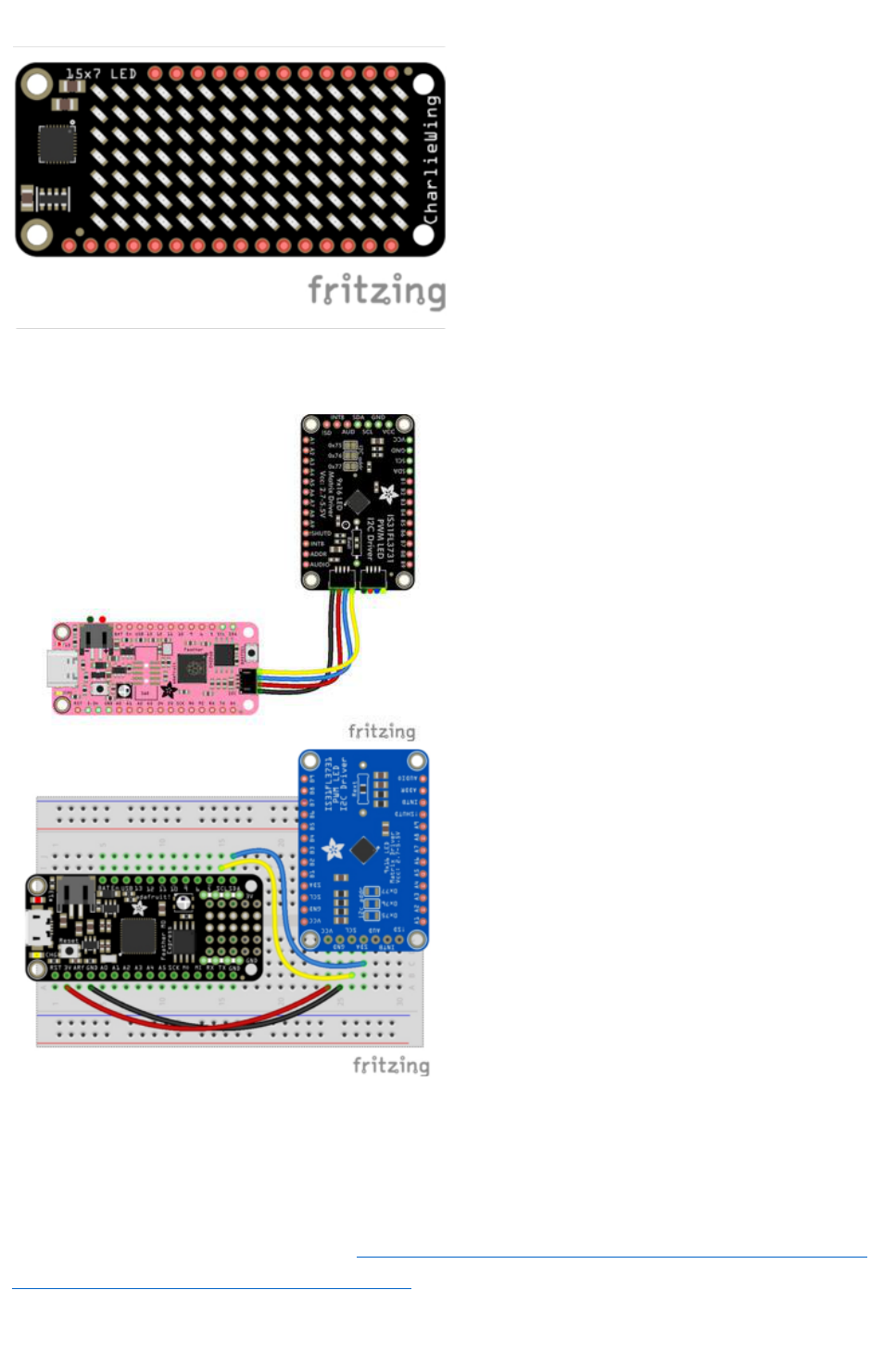
Assemble the CharlieWing by soldering
headers onto the board.
Once assembled, plug it into a Feather!
Here's an example of wiring a Feather to the breakout with I2C:
Board 3V to breakout VCC
Board GND to breakoutGND
Board SCL to breakoutSCL
Board SDA to breakoutSDA
Python Computer Wiring
Since there's dozens of Linux computers/boards you can use we will show wiring for
Raspberry Pi. For other platforms, please visit the guide for CircuitPython on Linux to
see whether your platform is supported().
©Adafruit Industries Page 29 of 48

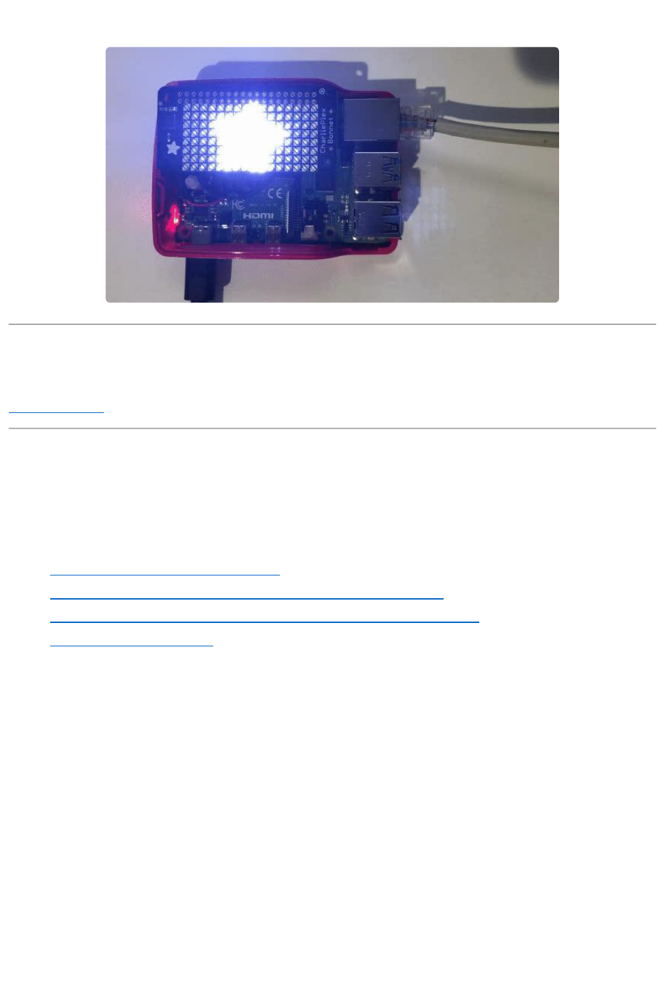
For the Bonnet, simply attach the Bonnet to your Raspberry Pi header.
Here is the CharliePlex Bonnet on a Raspberry Pi Zero:
The CharliePlex Bonnet comes fully
assembled. Simply plug it into your
Raspberry Pi!
Here's the Raspberry Pi wired to the breakout with I2C:
Pi 3V3 to breakoutVIN
Pi GND to breakoutGND
Pi SCL to breakoutSCL
Pi SDA to breakoutSDA
©Adafruit Industries Page 30 of 48

Python Installation of IS31FL3731 Library
You'll need to install the Adafruit_Blinka library that provides the CircuitPython
support in Python. This may also require enabling I2C on your platform and verifying
you are running Python 3. Since each platform is a little different, and Linux changes
often, please visit the CircuitPython on Linux guide to get your computer ready()!
Once that's done, from your command line run the following command:
sudo pip3 install adafruit-circuitpython-is31fl3731adafruit-
circuitpython-framebuf
If your default Python is version 3 you may need to run 'pip' instead. Just make sure
you aren't trying to use CircuitPython on Python 2.x, it isn't supported!
CircuitPython Installation of IS31FL3731 Library
You'll need to install theAdafruit CircuitPython IS31FL3731() library, and its
dependencies, into thelibfolder on yourCIRCUITPYdrive. Then you need to
updatecode.pywith the example script.
Thankfully, we can do this in one go. In the example below, click theDownload
Project Bundlebutton below to download the necessary libraries and thecode.pyfile
in a zip file. Extract the contents of the zip file, and copy theentirelibfolderand thec
ode.pyfile to yourCIRCUITPYdrive.
YourCIRCUITPY/libfolder should contain the following folders:
/adafruit_is31fl3731
/adafruit_bus_device
•
•
•
©Adafruit Industries Page 31 of 48

Full Example Code
# SPDX-FileCopyrightText: 2021 ladyada for Adafruit Industries
# SPDX-License-Identifier: MIT
import board
import busio
# uncomment next line if you are using Feather CharlieWing LED 15 x 7
from adafruit_is31fl3731.charlie_wing import CharlieWing as Display
# uncomment next line if you are using Adafruit 16x9 Charlieplexed PWM LED Matrix
# from adafruit_is31fl3731.matrix import Matrix as Display
# uncomment next line if you are using Adafruit 16x8 Charlieplexed Bonnet
# from adafruit_is31fl3731.charlie_bonnet import CharlieBonnet as Display
# uncomment next line if you are using Pimoroni Scroll Phat HD LED 17 x 7
# from adafruit_is31fl3731.scroll_phat_hd import ScrollPhatHD as Display
# uncomment next line if you are using Pimoroni 11x7 LED Matrix Breakout
# from adafruit_is31fl3731.matrix_11x7 import Matrix11x7 as Display
# uncomment this line if you use a Pico, here with SCL=GP21 and SDA=GP20.
# i2c = busio.I2C(board.GP21, board.GP20)
i2c = busio.I2C(board.SCL, board.SDA)
display = Display(i2c)
# draw a box on the display
# first draw the top and bottom edges
for x in range(display.width):
display.pixel(x, 0, 50)
display.pixel(x, display.height - 1, 50)
# now draw the left and right edges
for y in range(display.height):
display.pixel(0, y, 50)
display.pixel(display.width - 1, y, 50)
CircuitPython & Python Usage
To demonstrate the usage of the sensor we'll initialize it and manipulate the LED
matrix from the board's Python REPL.
To do this, connect to the board's serial REPL() so you are at the CircuitPython>>>pr
ompt.
NOTE: Due to size and design of each CharliePlex matrix form-factor, import and
initialisation is different for each. Make sure you're running the correct code for your
matrix!
First, run the following code to import the necessary modules:
import board
import busio
©Adafruit Industries Page 32 of 48

If you're using the CharliePlex breakout, initialise it by running the following code:
from adafruit_is31fl3731.matrix import Matrix as Display
If you're using the CharliePlex FeatherWing, run the following code:
from adafruit_is31fl3731.charlie_wing import CharlieWing as Display
If you're using the CharliePlex Bonnet, run the following code:
from adafruit_is31fl3731.charlie_bonnet import CharlieBonnet as Display
Now, no matter which board you are using, you'll create the I2C object and pass that
into Display .
i2c = busio.I2C(board.SCL, board.SDA)
display = Display(i2c)
When the display initializes it will go through and clear each frame (there are 8 frames
total) of the display. You might see the display momentarily flash and then turn off to a
clear no pixel lit image.
You can control all of the board's pixels using the fill function. Send to this function
a value from 0 to 255 where 0 is every LED pixel turned off and 255 is every LED
pixel turned on to maximum brightness. For example to set all the pixels to half their
brightness run:
display.fill(127)
You might notice some buzzing or ringing sounds from the display when all pixels are
lit, this is normal as the Charlieplex driver quickly switches LEDs on and off.
©Adafruit Industries Page 33 of 48

If you've used other displays like LED matrices you might notice the Charlieplex
module doesn't need to have a show function called to make the changes visible. As
soon as you call fill or other display functions the display will update!
You can turn all the pixels off with fill set to 0 :
display.fill(0)
Now for some fun! You can set any of the LED pixels using the pixel function. This
function takes the following parameters:
X position - The location of the horizontal / X pixel position.
Y position - The location of the vertical / Y pixel position.
Intensity- This is a value from 0 to 255 which specifies how bright the pixel
should be, 0 is off and 255 is maximum brightness. Use an in-between value to
show a less bright pixel.
For example to set pixel 0, 0 to full brightness run:
display.pixel(0, 0, 255)
Be careful setting all pixels to 255 maximum brightness! This might pull more
power than your computer's USB port can provide if you are powering your
board over USB. Use an external powers supply or battery when lighting lots of
LEDs to max brightness.
•
•
•
©Adafruit Industries Page 34 of 48

Or to set the pixel next to it horizontally to half brightness run:
display.pixel(1, 0, 127)
You can turn off individual pixels by setting them to an intensity of zero.
You can even make pixels blink! The board supports a fixed blink rate that you set
using the blink function. This function takes in the number of milliseconds to use
for the blink rate (but internally it can only blink in 270ms increments so you might not
get an exact match). For example to blink pixels about once every half second call:
display.blink(500)
You'll notice nothing actually changes on the board. This is because in addition to
intensity each LED pixel has a blink state which can be enabled and disabled. The fi
ll command can actually set all pixels and turn them on to blink:
display.fill(127, blink=True)
You can turn off the blinking by setting blink=False .
The pixel command supports the blink parameter too! You can turn on and off
blinking pixel by pixel as needed. For example to turn on blinking for pixel 0, 0 :
©Adafruit Industries Page 35 of 48

display.pixel(0, 0, 127, blink=True)
Currently the Charlieplex module is very simple and only exposes pixel set
commands. In the future more advanced graphics commands like line drawing, text
display, etc. might be implemented but for now you'll need to manipulate the pixels
yourself.
Finally the display supports holding up to 8 frames of pixel data. Each frame contains
an entire matrix of LED pixel state (intensity, blinking, etc.) and by default the module
starts you on frame 0. You can change to start displaying and drawing on another
frameby calling frame which takes these parameters:
Frame number - This is the frame number to make the active frame for display or
drawing. There are 8 frames total, 0 through 7 .
show - An optional boolean that defaults to True and specifies if the frame
should be immediately displayed ( True ) or just made active so that pixel and fill
commands draw on it but it's not yet shown.
For example to clear frame 1 and draw a few pixels on it, then display it you can run:
display.frame(1, show=False)
display.fill(0)
display.pixel(0, 0, 255)
display.pixel(1, 1, 255)
display.pixel(2, 2, 255)
display.frame(1) # show=True is the default, the frame will be displayed!
Notice how the first call switches to make frame 1 the active frame but doesn't display
it because show is set to false. Then the frame pixel data is changed with fill and pixel
commands, and finally the frame is shown by calling frame again but letting the
default show = True be used so the frame is displayed.
Using frames you can build simple animations by drawing each frame and swapping
between them over time!
•
•
©Adafruit Industries Page 36 of 48

That's all there is to the basic Charlieplex driver module usage!
Text Scrolling Example
NOTE: When running this example on Raspberry Pi, you must have the font8x5.bin file
found here() in the same directory as the program!
wget https://raw.githubusercontent.com/adafruit/
Adafruit_CircuitPython_framebuf/master/examples/font5x8.bin
# SPDX-FileCopyrightText: 2021 ladyada for Adafruit Industries
# SPDX-License-Identifier: MIT
import board
import busio
import adafruit_framebuf
# uncomment next line if you are using Feather CharlieWing LED 15 x 7
# from adafruit_is31fl3731.charlie_wing import CharlieWing as Display
# uncomment next line if you are using Adafruit 16x9 Charlieplexed PWM LED Matrix
# from adafruit_is31fl3731.matrix import Matrix as Display
# uncomment next line if you are using Adafruit 16x8 Charlieplexed Bonnet
from adafruit_is31fl3731.charlie_bonnet import CharlieBonnet as Display
# uncomment next line if you are using Pimoroni Scroll Phat HD LED 17 x 7
# from adafruit_is31fl3731.scroll_phat_hd import ScrollPhatHD as Display
# uncomment next line if you are using Pimoroni 11x7 LED Matrix Breakout
# from adafruit_is31fl3731.matrix_11x7 import Matrix11x7 as Display
# uncomment this line if you use a Pico, here with SCL=GP21 and SDA=GP20.
# i2c = busio.I2C(board.GP21, board.GP20)
i2c = busio.I2C(board.SCL, board.SDA)
display = Display(i2c)
text_to_show = "Adafruit!!"
# Create a framebuffer for our display
buf = bytearray(32) # 2 bytes tall x 16 wide = 32 bytes (9 bits is 2 bytes)
fb = adafruit_framebuf.FrameBuffer(
buf, display.width, display.height, adafruit_framebuf.MVLSB
)
frame = 0 # start with frame 0
while True:
for i in range(len(text_to_show) * 9):
fb.fill(0)
fb.text(text_to_show, -i + display.width, 0, color=1)
# to improve the display flicker we can use two frame
# fill the next frame with scrolling text, then
# show it.
display.frame(frame, show=False)
# turn all LEDs off
display.fill(0)
for x in range(display.width):
# using the FrameBuffer text result
bite = buf[x]
for y in range(display.height):
©Adafruit Industries Page 37 of 48

bit = 1 << y & bite
# if bit > 0 then set the pixel brightness
if bit:
display.pixel(x, y, 50)
# now that the frame is filled, show it.
display.frame(frame, show=True)
frame = 0 if frame else 1
Python Examples
If you want to expand the capabilities of the CharliePlex LED Matrix even more, we
can add Pillow into the mix. So we'll show you how to add Pillow and then go over a
couple of examples that use Pillow.
Additional Setup
If you haven't already installed the library, follow the setup section on the Python &
CircuitPython page. If you have, then continue.
DejaVu TTF Font
Raspberry Pi usually comes with the DejaVu font already installed, but in case it didn't,
you can run the following to install it:
sudo apt-get install ttf-dejavu
Pillow Library
We also need Pillow, also known as PIL, the Python Imaging Library, to allow using
text with custom fonts. There are several system libraries that PIL relies on, so
installing via a package manager is the easiest way to bring in everything:
sudo apt-get install python3-pil
That's it. You should be ready to go.
Speeding up the Display on Raspberry Pi
For the best performance, especially if you are doing fast animations, you'll want to
tweak the I2C core to run at 1MHz. By default it may be 100KHz or 400KHz
•
•
©Adafruit Industries Page 38 of 48

To do this, edit the config with sudo nano /boot/config.txt
and add to the end of the file
dtparam=i2c_baudrate=1000000
Reboot to 'set' the change.
Scrolling Marquee Example
The first example, we're going to take a look at an example that will take some text,
draw it in a TrueType font and then scroll the rendered text. Let's start by looking at
the code in each section.
We start by importing the libraries we need which include the board and a few Pillow
modules.
import board
from PIL import Image, ImageDraw, ImageFont
Next we do the import for the IS31FL3731 driver for the matrix itself. Since the different
boards have been split into their own modules, we just import the appropriate module
and alias it as Display .
For instance, if you have the breakout instead of the bonnet, you'll want to
uncomment that and comment out the bonnet line.
# uncomment next line if you are using Adafruit 16x9 Charlieplexed PWM LED Matrix
# from adafruit_is31fl3731.matrix import Matrix as Display
# uncomment next line if you are using Adafruit 16x8 Charlieplexed Bonnet
©Adafruit Industries Page 39 of 48

from adafruit_is31fl3731.charlie_bonnet import CharlieBonnet as Display
# uncomment next line if you are using Pimoroni Scroll Phat HD LED 17 x 7
# from adafruit_is31fl3731.scroll_phat_hd import ScrollPhatHD as Display
Next we set a couple of variables. We have the SCROLLING_TEXT variable. Go ahead
and change the text if you would like. It shouldn't matter how long, though you
probably shouldn't make it too long if you want to see it loop. You can set BRIGHTNES
S as well, in case you want to adjust the intensity.
SCROLLING_TEXT = "You can display a personal message here..."
BRIGHTNESS = 64 # Brightness can be between 0-255
Next we do the basic setup for the display by declaring the I2C object and passing
that into the display.
i2c = board.I2C()
display = Display(i2c)
Next we go ahead and load up the Deja Vu font into an object. We are going with an 8
pixel high font because that's the largest we can fit on the display and still see
everything.
# Load a font
font = ImageFont.truetype('/usr/share/fonts/truetype/dejavu/DejaVuSans.ttf', 8)
In this next part, we first start by getting the width and height of what the text would
be when rendered with the font we chose. Then we create a virtual image of that
width and height and draw the text onto it.
# Create an image that contains the text
text_width, text_height = font.getsize(SCROLLING_TEXT)
text_image = Image.new('L', (text_width, text_height))
text_draw = ImageDraw.Draw(text_image)
text_draw.text((0, 0), SCROLLING_TEXT, font=font, fill=BRIGHTNESS)
Next we create a virtual image that's the same size as the display. This will be where
we draw what we want to actually display.
# Create an image for the display
image = Image.new('L', (display.width, display.height))
draw = ImageDraw.Draw(image)
Finally we get to our main loop. We start by drawing a rectangle to be sure we are not
leaving any existing text behind. Then we paste our image of the text onto the
image we are going to display using the value of x , which represents the left offset
we want to use to give a nice scrolling effect. We have a for loop which will scroll
©Adafruit Industries Page 40 of 48

the complete text plus empty display width by one iteration. That's all placed inside an
infinite while loop for endless iterations.
while True:
for x in range(text_width + display.width):
draw.rectangle((0, 0, display.width, display.height), outline=0, fill=0)
image.paste(text_image, (display.width - x, display.height // 2 -
text_height // 2 - 1))
display.image(image)
Now go ahead and run the example code.
python3 is31fl3731_pillow_marquee.py
You should see the display showing a message scrolling from right to left.
Full Source Code
# SPDX-FileCopyrightText: 2021 ladyada for Adafruit Industries
# SPDX-License-Identifier: MIT
"""
Example to scroll some text as a marquee
This example is for use on (Linux) computers that are using CPython with
Adafruit Blinka to support CircuitPython libraries. CircuitPython does
not support PIL/pillow (python imaging library)!
Author(s): Melissa LeBlanc-Williams for Adafruit Industries
"""
import board
from PIL import Image, ImageDraw, ImageFont
©Adafruit Industries Page 41 of 48

# uncomment next line if you are using Adafruit 16x9 Charlieplexed PWM LED Matrix
# from adafruit_is31fl3731.matrix import Matrix as Display
# uncomment next line if you are using Adafruit 16x8 Charlieplexed Bonnet
from adafruit_is31fl3731.charlie_bonnet import CharlieBonnet as Display
# uncomment next line if you are using Pimoroni Scroll Phat HD LED 17 x 7
# from adafruit_is31fl3731.scroll_phat_hd import ScrollPhatHD as Display
SCROLLING_TEXT = "You can display a personal message here..."
BRIGHTNESS = 64 # Brightness can be between 0-255
i2c = board.I2C() # uses board.SCL and board.SDA
# i2c = board.STEMMA_I2C() # For using the built-in STEMMA QT connector on a
microcontroller
display = Display(i2c)
# Load a font
font = ImageFont.truetype("/usr/share/fonts/truetype/dejavu/DejaVuSans.ttf", 8)
# Create an image that contains the text
text_width, text_height = font.getsize(SCROLLING_TEXT)
text_image = Image.new("L", (text_width, text_height))
text_draw = ImageDraw.Draw(text_image)
text_draw.text((0, 0), SCROLLING_TEXT, font=font, fill=BRIGHTNESS)
# Create an image for the display
image = Image.new("L", (display.width, display.height))
draw = ImageDraw.Draw(image)
# Load the text in each frame
while True:
for x in range(text_width + display.width):
draw.rectangle((0, 0, display.width, display.height), outline=0, fill=0)
image.paste(
text_image, (display.width - x, display.height // 2 - text_height // 2 -
1)
)
display.image(image)
Animated GIF Example
Next let's take a look at an animated GIF player example. First we'll start by
downloading an animated GIF and copying that into the same folder as the script as a
dafruit-star-rotating.gif. It looks tiny and that's because it is. It is 8x8 pixels which
works out nicely for the CharliePlex matrix.
Download Rotating Star
Now let's start with the first section, the imports. You may be surprised that this code
uses fewer Pillow modules than the previous example. We are also adding sys ,
which we mostly use for passing the name of an animated gif.
import sys
import board
©Adafruit Industries Page 42 of 48

from PIL import Image
import adafruit_is31fl3731
Next we do the usual setup for the CharliePlex display.
i2c = board.I2C()
# uncomment line if you are using Adafruit 16x9 Charlieplexed PWM LED Matrix
#display = adafruit_is31fl3731.Matrix(i2c)
# uncomment line if you are using Adafruit 16x9 Charlieplexed PWM LED Matrix
display = adafruit_is31fl3731.CharlieBonnet(i2c)
Now we make sure the user specified a gif file, so we have something to work with
that's not hard-coded and open the file. If the file wasn't specified, we are using sys.
exit() , since that is the preferred way to do it if you are importing sys anyways.
# Check that the gif was specified
if len(sys.argv) < 2:
print("No image file specified")
print("Usage: python3 is31fl3731_pillow_animated_gif.py animated.gif")
sys.exit()
# Open the gif
image = Image.open(sys.argv[1])
We need to check that this is an animated gif. While we could have just displayed it as
a static gif in this case, the point was to show how to display the animation.
# Make sure it's animated
if not image.is_animated:
print("Specified image is not animated")
sys.exit()
Next we get some gif animation information such as the delay. Only the duration of
the first frame is extractable at the time of this writing with Pillow.
# Get the autoplay information from the gif
delay = image.info['duration']
The loop number is a little trickier because it means different things between the
IS31FL3731 chip and an animated gif. With an animated gif, it is guaranteed to play at
least once and then loop by the number of times is provided by the loop value, unless
it is zero, which means forever.
With the IS31FL3731, loops mean exactly the number of loops to play the animation,
unless it is zero, in which case it will play forever.
©Adafruit Industries Page 43 of 48

So if loop is 0, we just pass it on. If we only want to play the animation once, then l
oop is not provided in the image information. If it is more than once, we need to
count the first time it plays plus the number of times to loop the animation.
# Figure out the correct loop count
if "loop" in image.info:
loops = image.info['loop']
if loops > 0:
loops += 1
else:
loops = 1
Next, we need to make sure these values are in the ranges that the driver likes. The
number of frames in the animation is available from the property n_frames and the
IS31FL3731 can handle a maximum of 8 frames, so if a longer animation is provided,
only the first 8 frames are used.
# IS31FL3731 only supports 0-7
if loops > 7:
loops = 7
# Get the frame count (maximum 8 frames)
frame_count = image.n_frames
if frame_count > 8:
frame_count = 8
Now that we have a frame count, we will go through each of those frames and load
the frame image into the IS31FL3731 using the paste function and center the image.
First the frame is converted to a 256-grayscale image, which is what mode L is, and
then it is copied into a centered position, which is calculated from the difference in
size between the display and image. After that, it is inserted as the current frame
number.
# Load each frame of the gif onto the Matrix
for frame in range(frame_count):
image.seek(frame)
frame_image = Image.new('L', (display.width, display.height))
frame_image.paste(image.convert("L"), (display.width // 2 - image.width // 2,
display.height // 2 - image.height // 2))
display.image(frame_image, frame=frame)
Finally, we call the auto_play function using the delay and loop information from the
animated gif.
display.autoplay(delay=delay, loops=loops)
Now go ahead and run the example code.
python3 is31fl3731_pillow_animated_gif.py adafruit-star-rotating.gif
©Adafruit Industries Page 44 of 48
You should see the rotating star appear on the display.
Python Docs
Python Docs()
Downloads
Files
EagleCAD PCB files on GitHub()
Original Fritzing object in the Adafruit Fritzing library()
STEMMA QT Fritzing object in the Adafruit Fritzing library()
IS31FL3731 Datasheet()
•
•
•
•
©Adafruit Industries Page 45 of 48

STEMMA QT Schematic and Fab Print
©Adafruit Industries Page 46 of 48

Original Schematic and Fab Print
16x9 0603 LED Grid
Schematics & Fabrication print (dimensions in inches)
©Adafruit Industries Page 47 of 48

©Adafruit Industries Page 48 of 48
