
ISO-15288, OOSEM and
Model-Based Submarine Design
Paul Pearce
1
and Matthew Hause
2
1
Senior Systems Engineer
Deep Blue Tech Pty Ltd,
Osborne, SA 5017, Australia
Email: [email protected]
2
Atego Chief Consulting Engineer
5930 Cornerstone Court West, Suite 250
San Diego, CA 92121, USA
Email: [email protected]
Abstract. When tasked with the development of a large and complex system of systems it is
necessary that a project operates according to current best practice in all domains including systems
engineering. These practices have been documented by organisations such as INCOSE and the
International Organisation for Standardisation (ISO). Model-based systems engineering (MBSE) is
currently considered a best practice approach to the specification, design, analysis and verification of
a complex system. A model-based design approach can leverage the benefits of a system model to
integrate multiple domains in a more precise, consistent, traceable and re-usable format than
traditional document-centric design processes.
ISO-15288, published by ISO, is a world-wide standard for systems and software engineering
lifecycle processes. This standard defines a framework of processes that can be applied to a system
throughout its full lifecycle, including requirements definition and analysis, architectural design,
implementation and verification.
The Object-Oriented Systems Engineering Method (OOSEM) was developed in 1998 and has since
been refined by the INCOSE OOSEM Working Group and others. When applied in conjunction with
the Systems Modelling Language (SysML), OOSEM is widely advocated as an example of MBSE
best practice.
In Deep Blue Tech (DBT), submarine concept formulation activities are supported by a framework of
model-based SE processes. Motivated by the introduction of MBSE to a requirements analysis and
design team, a study was undertaken to explore a mapping between DBT design processes and the
integrated processes defined in OOSEM and ISO-15288. This paper will discuss a number of
observations from the study and how they were used to update DBT processes to enable a successful
development strategy.
INTRODUCTION
A military submarine is a very complex system-of-systems. Most of these systems are integrated
within the confines of a pressure hull. This key constraint means that most submarine systems are
highly coupled, physically and often operationally. This leads to emergent behaviour and properties
that are often as undesirable as they are unintended. Further complicating this situation, the increasing
fraction of embedded software and the integration of COTS equipment in submarine systems require a
design that accommodates frequent hardware and software upgrade cycles (Mitchell 2010). The
submarine designer performs a critical and centralising role within an enterprise of many
organisations - generating, integrating and evolving design information at every level of the
submarine design. In order to execute this role and deliver value for money, the designer must be
equipped with the best available personnel, tools and processes.
In late 2007, Deep Blue Tech was established as a wholly-owned subsidiary of the Australian
submarine and shipbuilding organisation, ASC. The mission of DBT is to be “the designer for the
entire lifecycle of Australia's Future Submarine” (DBT 2012). Towards this end, DBT conducts
research and development of concepts for Australia’s Future Submarine as outlined in the 2009
Defence White Paper (DWP 2009). DBT has expended considerable effort researching and
understanding the latest technology and industry best practice relating to submarine systems design
(Wicklander 2012).
It was recognised very early in the formation of DBT that there is a strong need to communicate and
coordinate the design products and processes deployed across the submarine enterprise. DBT
continues to evolve a framework of processes to support the requirements definition and concept
design phases of the anticipated submarine project. In pursuit of industry best practice, this framework
has been compared with the international standardised framework of system lifecycle processes
defined in ISO-15288 (ISO/IEC 2008) and the INCOSE Object-Oriented Systems Engineering
Method (OOSEM) (INCOSE 2008).
The outputs of traditional submarine design processes are predominantly document-centric, in that
much of the engineering design information is captured, indeed locked into electronic text-based
reports and drawings. This is a very brittle format and in a high-flux design environment, trying to
maintain consistency within a document, let alone across a document set, requires exceptionally high
levels of fastidiousness. As a result of this, engineering documentation is often obsolete upon
configuration and release. The solution is to manage design information in a more malleable, precise
and accessible format: computer models. This is the objective of Model-Based Systems Engineering
(MBSE); a paradigm that elevates the 'system model' to prominence as the integrating framework for
the 'specification, design and analysis' of a system (Friedenthal et al. 2008). MBSE is becoming best-
practice across a range of industries involved in the development of complex system-of-systems and
has been adopted in DBT (Pearce 2011). Applied as a methodology, MBSE is a framework of
processes, methods and tools. A number of MBSE methodologies exist, some more or less tool-
independent. OOSEM is one tool-independent methodology and was chosen for the study outlined in
this paper.
If ISO-15288 defines 'what' needs to be done, then OOSEM defines 'how' that can be done, and at
their intersection lie the design processes deployed in DBT. This paper will focus on a subset of the
technical processes defined in ISO-15288 and OOSEM considered most relevant to the current phase
of the Future Submarine project, namely those processes involved with requirements elicitation,
requirements analysis and architectural design. Many equally important and cross-cutting processes,
such as verification and validation are outside the scope of this paper, but were not absent from the
original study.
The conclusion to this paper will summarise the most salient lessons and issues covered in the body of
this report.
ISO-15288
As an international standard, ISO-15288 is intended to harmonise the framework of processes used by
any organisation or project throughout the full lifecycle of a man-made system. This standard has its
heritage in earlier efforts to standardise systems engineering (SE) processes and products, including
systems development (EIA-632) (EIA 1999), and systems engineering management (IEEE-1220)
(IEEE 1998). In ISO-15288, SE processes are organised into five groups; Agreement, Enterprise,
Project, Technical and Special. The Technical group of SE processes comprises;
Stakeholder Requirements Definition;
Requirements Analysis;
Architectural Design;
Implementation;
Integration;
Verification;
Transition;
Validation;
Operation;
Maintenance, and;
Disposal.
As stated earlier, this paper looks more closely at the first three processes in this list. When combined
iteratively and recursively to a system, they constitute the majority of the work undertaken by a
designer of a submarine during the concept and preliminary design phases.
MODEL-BASED SYSTEMS ENGINEERING (MBSE)
Advances in computing power and the evolution of computer-aided design technologies such as 3D-
CAD and SysML have enabled organisations to shift their design approach from document-centric to
model-based practices. It is now possible to enhance the quality of system specifications and design
by capturing this information as elements and relationships in a model, and reusing elements across
multiple diagrams. By virtue of entering information into a computer model, a high level of precision
and consistency can be achieved. Furthermore, traceability between levels of abstraction in the design
(as discussed later in this paper) can be defined explicitly in the model as relationships between
elements.
A number of MBSE methodologies are currently used by the systems engineering community,
employing a range of processes and preferred tools, including;
IBM Rational Harmony for Systems Engineering (Hoffmann 2011)(IBM 2011)
IBM Rational Unified Process for Systems Engineering (RUP®SE) (Nolan 2008)
INCOSE Object-Oriented Systems Engineering Method (OOSEM) (INCOSE 2008)
Vitech MBSE Methodology
JPL State Analysis (SA)
Dori Object-Process Methodology (OPM) (Dori 2002)
SYSMOD (Weilkiens 2007)
DSTO Whole-of System Analytical Framework (WSAF) (Robinson et al. 2010)
This paper will look more closely at OOSEM. The reader is also directed to the survey by Estefan
(Estefan 2008) which provides an informative overview of the first six methodologies listed above.
DEFINING “OBJECT-ORIENTED” DESIGN
Almost all MBSE methodologies today are object-oriented (OO). OO is a term that encapsulates
several powerful techniques for describing a design. At the whole-of-system level however, OO is
rarely associated with established submarine and shipbuilding design processes.
The term OO originates from the development of third generation software programming languages.
These languages provide a higher level of abstraction than second and first generation languages
(assembly and machine-code respectively), and introduced a number of powerful techniques for
defining software constructs, including classes, objects, inheritance and aggregation. Beginning in the
1980s, graphical modelling tools were created to assist software developers define and communicate
the structure and behaviour of their software with a standard set of diagrams. Notable efforts by
Booch (Booch 2007), Rumbaugh (Rumbaugh et al. 1991) and Jakobsson (Jakobsson et al. 1992)
defined OO notations for these diagrams and this work was eventually combined in 1997 to create the
Unified Modelling Language (UML) (OMG 2011a) .

By 2000 it was clear that the global systems engineering community lacked a standardised domain-
independent language for modelling complex systems. Indeed OOSEM was developed at that time to
equip systems engineers with OO techniques and modelling (Lykins, Friedenthal, Meilich, 2000). By
this time, UML had proven to be very good at supporting the system lifecycle processes and abstract
concepts already familiar to systems engineers. This led INCOSE and OMG to develop an extension
to UML for modeling systems. In 2007 OMG released the Systems Modelling Language (OMG
SysML™) specification (OMG 2011b), borrowing and extending many of the OO concepts, elements,
relationships and diagrams found in UML.
In DBT it has been important to articulate what ‘object-oriented’ means to engineers who are
unfamiliar with software terms such as ‘inheritance’ and ‘instantiation’. That is not to say the
individual concepts are difficult to grasp, but many engineers have not been exposed to these terms
and in a context they can relate to. A mechanical engineer certainly understands that a screw is a type,
or variant, of fastener, and that Widget X uses four of that type of fastener. An example is provided in
Figure 1. A fastener can be viewed as an abstraction; a definition of the general properties of a screw
that it shares with other fasteners, such as a rivet or nail. Furthermore, the screw ‘inherits’ the general
properties of a fastener (e.g. length) and then defines additional screw-specific properties (e.g. thread
diameter and pitch), which can then be inherited by other variants of screws.
Figure 1: An Example of Inheritance and Instantiation in SysML
In Figure 1, Widget X has four Screws as represented by the black diamond and the number 4. In
other words, a common definition of a Screw, as might be found in a component catalogue, is reused,
indeed ‘instantiated’, four times for each instance of Widget X.
As universal as these OO concepts may be, when combined and applied to complex systems of
systems, they present a significant learning curve for those unfamiliar with software development
terminology. In DBT, where systems engineers are equipping domain-specific engineers with model-
based systems engineering tools and techniques, the term OO is sometimes perceived as ‘software
jargon’. It has been found that OO concepts best crystallise in engineer’s minds through practical
experience and examples using physical systems as shown above. Given this lesson, perhaps OOSEM
is shackled by its OO prefix, and despite its origins, would perhaps find a wider audience if “OO”
were replaced with Model-Based or Model-Driven.

THE OBJECT-ORIENTED SYSTEMS ENGINEERING METHOD (OOSEM)
OOSEM provides an integrated framework that combines object-oriented techniques, a model-based
design approach and traditional top-down 'waterfall-style' SE practices. Originally based on UML
modelling, OOSEM was realigned with SysML in 2006 and is now widely advocated as an example
of MBSE best practice. A detailed tutorial is provided on the INCOSE website (INCOSE 2008) and
an overview is provided in the INCOSE SE Handbook (Haskins 2010). An example application of
OOSEM is also described in detail in chapter 16 of (Friedenthal et al. 2008).
The following activities are defined in OOSEM;
Analyse Needs;
Define System Requirements;
Define Logical Architecture;
Synthesize Allocated Architectures;
Optimise and Evaluate Alternatives, and;
Validate and Verify Systems.
As a set, all of these activities, like their counterparts in ISO-15288, are intended to be performed
iteratively and recursively to develop a system-of-systems. It was this observation about iteration and
recursion that motivated the creation of a matrix to cross-reference ISO-15288 technical processes
with the corresponding OOSEM activities. The purpose of this activity was not to identify gaps in
OOSEM or ISO-15288, but rather provide a best-practice context for reviewing DBT processes and
products.
THE DBT SE PROCESS FRAMEWORK
The processes used in DBT to define and develop a submarine design are organised into four
categories, as illustrated in Figure 2.
Figure 2: Deep Blue Tech SE Process Framework
Requirements
Development
Architectural
Design
Synthesis
Technical
Evaluation
Objective Measures,
Functions and
Requirements
Function and Logical
Architecture
Objective Measures and
Re
q
uirements
Objective
Measures
Evaluation
Objective
Measures
Evaluation
results
Evaluation
results
Arran
g
ements
Ph
y
sical Architecture
Stakeholder Needs

These four categories are conducted iteratively over several phases, and in parallel to each other,
culminating in regular reviews. This framework is also intended to be applied recursively, at each
level of the design (i.e. Whole-of-Submarine, Sub-systems and Parts). Thus what is, at least
conceptually, a simple framework of processes, conceals a far more complicated multi-dimensional
challenge when implemented.
Table 1 provides a mapping between ISO-15288, OOSEM and, in the grey boxes the DBT
Requirements Development, Architectural Design and Synthesis process groups. The next three
sections will examine three subsets of this matrix. A fourth group, Technical Evaluation, consolidates
all evaluation processes, including trade-studies, engineering analysis, technical performance
measurement as well as V&V. During each design phase, evaluation activities are expected to define
and analyse objective measures that are commonly defined for a system-of-interest and provide
feedback to the other three process groups.
OOSEM Activity
ISO-15288 Process
Eliciting
Stakeholder
Requirements
Requirements
Analysis
Architectural
Design
Verification & Validation
(separate processes)
Analyse Needs Requirements
Development
Define System
Requirements
Requirements
Development
Define Logical
Architecture
Architectural
Design
Synthesize
Allocated
Architectures
Synthesis
Optimise and
Evaluate
Alternatives
Technical Evaluation
Validate and
Verify System
Technical Evaluation
Table 1: Mapping ISO-15288, OOSEM and DBT SE Process Framework
ELICITING STAKEHOLDER REQUIREMENTS
In this first group of activities, stakeholder requirements for the system are gathered and analysed.
From the start, OOSEM defines a 'usage-driven' design approach; defining user interactions with the
system and elaborating these use cases with operational scenarios that are defined in terminology
native to the end-user.
Usage- versus Feature-Driven Design
A usage-driven approach ensures functional requirements are traced directly to the user’s operational
requirements, which in turn ensures the design is influenced foremost by the end-user’s needs. This
can be contrasted with a more traditional feature-driven approach where desired features, functions or
capabilities are listed for a system, often defined by domain experts and engineers in consultation with
the end-users. What is the difference between usage and features? Features are functions that a system
is expected to perform. System usage can be viewed as a combination of system features applied in a
particular context to satisfy the user’s needs, goals and capabilities (Nolan et al. 2008).
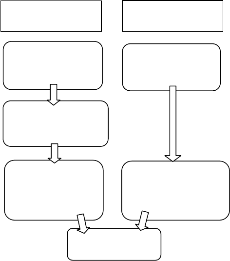
Figure 3 illustrates the difference between usage- and feature-driven approaches.
Figure 3: Comparing Usage- and Feature-Driven Design Approaches
Established submarine designers understand the features of the systems they are designing and
traditionally evolve each new design from past designs by adding or subtracting features with each
iteration. For an organisation challenged with building a new submarine design from first principles, a
complete and fully traceable list of features is essential. A usage-driven design method provides the
best chance of achieving this goal.
In the Australian defence acquisition context, a usage-driven approach is also prescribed in the
Capability Definition Documents Guide (CDG 2005). That document provides detailed guidance on
the preparation of user requirements documentation, including examples, and outlines a process that
incorporates CONOPS, operational scenarios and the consolidation of top-level functions for the
system-of-interest.
Existing Design Analysis
The task of comparing ISO-15288 and OOSEM revealed a number of gaps in the DBT process
framework. Most of these missing processes were defined in OOSEM and were involved with
stakeholder requirements definition, including;
existing design ‘As-Is’ analysis;
causal analysis, using the ‘fishbone diagram’; and
understanding the transition of a capability from ‘As-is’ to ‘To-Be’;
Indeed, the first activity described in OOSEM is the characterisation of the current system (if it exists)
in terms of its stakeholders, enterprise context, usage and design. This work helps to identify re-use
candidates (existing sub-systems that can be reused in the new design), document relevant operating
procedures and doctrine, and reveal aspects of the current system that can be improved upon. For
DBT, the Collins Class submarine represents the ‘As-Is’ solution. The experiences from that project
are well-known within the Australian defence community (McIntosh, Prescott 1999) (Yule, Woolner
2008).
Define scenarios where
the System-of-Interest
is used in an
operational context
Consolidate top-level
functions from scenarios
and allocate them to the
S
y
stem-of-Interest
Elaborate each top-
level function with
internal scenarios that
identify sub-functions
of System-of-Interest
Specify top-level
functions (“Features”)
and allocate to System-
of-Interest
Decompose functions into
sub-functions of System-
of-Interest
Allocate sub-functions
to logical sub-systems
“Usage-Driven”
Design Approach
“Feature-Driven”
Design Approach

Identification of Measures
Another activity performed during requirements elicitation and defined in OOSEM is the
identification of measures of effectiveness (MOEs). These measures are defined by asking 'how well'
the submarine system (including its payload and crew) is expected to perform in particular scenarios.
Importantly, a concise list of MOEs focuses the designer on the most important 'usages' of a system.
A corresponding set of Measures of Performance (MOPs) can then be assigned to features that when
combined enable the 'use' of the system. Both MOEs and MOPs should be defined and captured in the
system model, traceable to each other, the user’s needs and the systems to which they are associated.
REQUIREMENTS ANALYSIS
The usage-driven method discussed earlier in this paper generates use cases and scenario diagrams
that describe the intended behaviour of a system. In OOSEM, system requirements are modelled in
this way, starting with the definition of the system as a ‘black-box’.
Black-Box and White-Box Views
It is instructive to view a system as a black-box first without exposing the internal details of the
system. Context diagrams, use cases and scenarios can describe a black-box system in terms of its
interaction with its surrounding environment and external entities. By defining a system as a black-
box first; the emphasis is placed on the identification and definition of key external interfaces,
properties and the usage of the system in a wider context. This type of description bounds the problem
that the end-user wants to have solved, without predetermining a solution.
As a subsequent step, the designer can then consider the system-of-interest as a ‘white-box’, where
the internal behaviour and details of that system and its subordinate systems are elaborated. Once
again, context diagrams, use cases and scenarios can be developed for the system and this time they
describe interactions between sub-systems. A white-box description therefore begins to characterise a
system solution.
Complex system-of-systems are often decomposed into several levels, and in OOSEM, at least three
design levels are identified; Enterprise, System and Logical Sub-system. If each design level is
considered, a ‘System-of-Interest’
1
, then it is possible to identify the corresponding black-box and
white-box scenarios for each level, as illustrated in Table 2.
System-of-Interest
(Level of Design)
OOSEM Black-Box
Scenario
Corresponding OOSEM White-Box Scenario
Enterprise Mission Scenario System Scenario
System System Scenario Logical Scenario
Logical Subsystem
(recursively)
Logical Scenario Logical Scenario (recursively)
Table 2: Defining Black-Box and White-Box Scenarios in OOSEM
The scenarios defined in OOSEM are equivalent to Function-Flow Block Diagrams (FFBDs)
2
. Indeed
scenarios are types of FFBDs; only the scope of the function is changed. In other words, a black-box
FFBD defines the functional flow and interfaces for top-level functions performed by a system in a
1
In this paper, the System-of-Interest is synonymous with ‘Level of the Design’, in that the lifecycle processes
involved in the development of a system can be applied recursively for each of its sub-systems. This aligns
with ISO-15288 and the guidance found in ISO/IEC TR 19760.
2
More information on FFBDs can be found in Appendix A of (Blanchard, Fabrycky 1998) and supplement 5-A
of (DAU 2001).

particular operational context, whilst a white-box FFBD defines the functional flow between internal
functions of that system.
In DBT, a requirements analysis workshop will develop several black-box scenarios for a system.
From these scenarios, it is possible to consolidate a minimal set of top-level functions for that system.
These top-level functions form the starting point for an architectural design workshop, where each
function is defined by a use case, and then further refined with a number of white-box scenarios for
that system. Figure 4 illustrates how top-level functions are consolidated from a set of black-box
scenarios and allocated to a System-of-Interest. These functions are then elaborated with a set of
white-box scenarios.
Figure 4: How Scenarios Define and Elaborate the System-of-Interest
DBT has developed an “Operational Concept Definition” process that is performed during the
requirements analysis workshop. This process incorporates the concepts of black-box and white-box
views to develop operational concepts as described in Jorgensen et al. (Jorgensen et al. 2011). This
process can be applied recursively to define a model-based system specification at each level of the
design.
Parametric Requirements Analysis
Returning to the topic of MOEs and MOPs, performance requirements are often incomplete or vague
about the operating conditions against which they need to be achieved. Ambiguity often leads the
designer to make assumptions about the conditions implied by a requirement, which can lead to a
solution that is not optimal or does not perform the way the user intended. DBT has adapted a method
from the work of Bijan et al. (Bijan et al. 2011), which utilises the SysML parametric diagram to
uncover undefined conditions and to check if the desired performance can be achieved under the
stated conditions. This method also helps to check that MOPs contribute to the MOEs as defined, and
if there is any available trade-offs between MOPs. The parametric analysis described in this section
complements the ‘Define System Requirements’ activity in OOSEM.
“Black Box” scenarios that describe how the System-of-Interest is used
“White Box” scenarios refine top-level functions of the System-of-
Interest and provide “usage” context for its sub-systems
Passage through Strait
Consolidated top-level
functions or use cases
e.g. “provide own-ship
position”
External function to the
System-of-Interest
(performed by another
system)
Internal sub-function
of the System-of-
Interest (to be
allocated to sub-
systems)
Anti-Submarine
Warfare Operation
System-of-Interest
e.g. Ships Navigation
System
Internal Navigation System
processes to provide own-ship
position
Conduct Training
ARCHITECTURAL DESIGN
The ISO-15288 definition of the Architectural Design process transforms system requirements into a
physical architecture, generating a logical architecture along the way. In the OOSEM framework,
Architectural Design is defined as two distinct activities; “Define Logical Architecture” and
“Synthesise Allocated Architectures”, the latter activity corresponding to the development of a
physical architecture. In both cases, architectural design processes involve the development of
diagrams and artefacts that describe the intended behaviour and structure of the System-of-Interest. It
can also be seen that both ISO-15288 and OOSEM describe architecture in terms of two levels of
abstraction; logical and physical.
Levels of Abstraction
Developing and viewing a design at different levels of abstraction can help manage system
complexity. Abstraction is used for this purpose to reveal only information and properties of the
system that are relevant to a particular level. Conversely, irrelevant low-level details are hidden from
the viewer at that level of abstraction. Perhaps the most abstract representation of the system is the
needs of system stakeholders, captured as requirement statements, and high-level diagrams. The least
abstract (most concrete and complicated) representation is the physical architecture detailed in
drawings and datasheets for real-world components. Logical and functional architectures are
respectively more abstract representations of physical architecture. Functional architecture is
comprised of solution-independent descriptions such as an FFBD; whilst logical architecture describes
solutions in terms of logical components that represent technology and implementation independent
abstractions of physical components.'. Physical architecture then defines a specific design
implementation corresponding to a particular logical architecture.
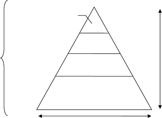
Figure 5: Levels of System Architecture and Abstraction
Defining a system with several layers of abstraction is powerful for two reasons. Firstly, it supports
iterative development, removing the need to impose physical solutions too early in the design process.
Secondly, it clarifies the design rationale for a system; e.g. a physical system solution is traced to a
more general logical solution, to which is allocated behaviours or functions that satisfy certain system
requirements. An illustrative example is provided in Figure 6.
The «allocate» relationship in SysML is intended to provide a way to define and relate system model
elements that are defined at different levels of abstraction.
Physical Architecture
Logical
Architecture
Functional
Architecture
User and System
Requirements (e.g.
mission use cases and
the system black box
specification)
most
abstract
least
abstract
volume of design information
g
enerated b
y
desi
g
n
p
ro
j
ect
For any
System-of-
Interest

Figure 6: Three Levels of Abstraction – a Diesel Generator Example
Synthesis Processes are Domain Specific
Blanchard and Fabryky define synthesis as “the creative process of putting known things together into
new and more useful combinations” (Blanchard, Fabrykcy 1998). Within the context of the DBT
process framework, synthesis activities transform requirements and logical architecture into a physical
architecture. In DBT, synthesis processes are very specific to the submarine design domain. In their
widely used submarine concept design textbook, Burcher et al describe the submarine concept design
process as “primarily an act of synthesis” (Burcher, Rydill 1994). This opinion is also shared by Lamb
et al with regard to the well-established ship design spiral, explaining that “…the ship designers’
move through the design process in a sequential series of steps, each dealing with a particular
synthesis or analysis task” (Lamb 2003).
The formulation process that gives rise to a submarine concept is focussed on rapid iterations of
parametric ('boats-by-numbers') designs that are characterised by existing physical solutions (Plant
2011). These point studies take key requirements and ‘turn the handle’ on the numbers to get an
approximate physical design in terms of size, power and weight. At the whole-of-submarine level, this
work eschews functional analysis or logical design altogether, instead focusing on the analysis of key
performance requirements and design decisions to characterise a hull form and key systems such as
main propulsion and batteries. This work is at the core of a submarine design capability and the
results of these activities significantly constrain the architecture of the submarine in subsequent design
phases.
In OOSEM, candidate physical architectures are comprised of nodes, which represent the aggregation
of physical components (at a particular location). Logical system components are then allocated to
these physical nodes. The manner in which these nodes are connected can be based on existing design
patterns or ‘reference architectures’, such as a centralised or distributed design. In OOSEM these
physical nodes are characterised as hardware, software or data, however, it is unusual to view a
submarine architecture in these terms. Only two major submarine sub-systems; the ships management
system and combat system, naturally decompose into hardware, software and data, being as they are
both software-intensive systems. By contrast, ship systems design is traditionally divided into
mechanical and electrical domains, and often less attention is given to software and data requirements
during the early iterations of system synthesis. Nevertheless, almost all modern submarine systems
interface with the ships management system and most possess an increasing percentage of software to
support local control and monitoring. The trend towards tighter integration of submarine systems,
combined with requirements for increased levels of automation and computer monitoring, are
expected to promote the role of software and data during the submarine design process. Software-
centric systems aside, a ‘reference architecture’ approach still applies to traditional submarine design,
and decades of development and experience have proven the architecture of many submarine sub-
systems. For example, to the trained eye, the submarine trim and weight compensation systems can be
Diesel
Generato
r
Generate
electrical power
MegaGen
5000 Series
Alternative logical
system solutions
Alternative physical
system solutions
Function
Logical System
Physical System
(Product/Assembly)
Allocation of functions to
logical systems
according to partitioning
criteria
market survey/trade-studies,
e
q
ui
p
ment selection
readily identified on any class of submarine. This is because the fundamental operating principles
have not changed, and even if each designer provides a different implementation, the general
architectural pattern remains the same. The electrical distribution system architecture can also be
characterised in terms of a centralised or distributed architecture, and that debate continues to this day.
Technology studies and market surveys support synthesis activities in DBT, as these processes enable
the development or selection of physical solutions at the sub-system level. Batteries, AIP units, diesel
generator sets and reverse-osmosis units are all examples of systems that are subject to these
processes.
IN PRACTICE
This paper has introduced, at a high level, the framework of model-based design processes deployed
in DBT. Putting these processes into practice is achieved through full-day workshops focussed on
sub-sets of the process framework. For example, the architectural design workshop is focussed on the
development of white-box scenarios, functional allocation (through swim-lanes on FFBDs), and
system structure such as internal block diagrams and system decomposition.
A common concern is ‘how much’ effort should be invested in developing functional and logical
architecture for a system? Resources are scarce in most projects, and developing a suite of black-box
scenarios takes time. Indeed, care must be taken to develop a set of scenarios with minimal overlap,
whilst at the same time providing maximum coverage of the functions most needed by the end-user.
Addressing this issue involves understanding the priorities of the end-user and using the MOEs and
MOPs as a guide to ensure that scenarios at least include the functionality associated with these
measures. Furthermore, it is difficult to hold back engineers from developing solutions in lieu of
requirements analysis and the definition of a logical design. Consequently, DBT design processes
account for concurrent top-down and bottom-up design, supported by regular issue identification and
resolution.
In DBT, systems engineers are part of a team that is comprised of a wide range of disciplines relevant
to submarine design, and they support this team by facilitating the requirements and design workshops
mentioned above. Systems engineers also manage the processes, methods, tools and training relating
to MBSE and the DBT SE process framework. This approach befits an adaptive integrated design
team where engineers are required to learn skills beyond their core domain, including MBSE. That
cross-functional up-skilling is intentional and needed to build a team as an integrated submarine
design capability.
CONCLUSIONS
A study was undertaken by DBT to compare equivalent ISO-15288 and OOSEM processes with the
objective of improving the SE process framework developed for DBT. This exercise revealed some
gaps in current processes, particularly with regard to ‘As-is’ design analysis. More importantly, this
study revealed a number of important and interrelated concepts. The following observations were
discussed in this paper.
Firstly, in DBT the processes that analyse requirements and produce a logical architecture are agnostic
to any domain application and align well with both ISO-15288 and OOSEM. The synthesis of a
physical architecture, however, requires design processes that are very specific to submarine design,
certainly for submarine concept formulation and particularly at the whole-of-system level. The
framework of processes defined for DBT, as for ISO-15288 and OOSEM are intended to be applied
iteratively by design phase and recursively by design level
For the purposes of DBT, where designs are developed from first principles, a usage-driven approach
as found in OOSEM focuses the team on the needs of the end-user and supports the development of a
design that can be traced to a documented understanding of how the submarine is operated. In the
submarine industry however, where new submarine designs are often the product of gradual
evolution, a feature-driven design approach is still favoured by engineers, and a hybrid approach
appears to be the best solution.

Specifying a system as black-box focuses the designer’s attention on the core functionality and
interfaces, whilst a white-box view reveals how the system will meet the specification. This approach
is defined in OOSEM at three levels of the design: Enterprise, System and Logical Sub-system. Using
black-box and white-box views help to separate the problem from the solution, however, these terms
are unfamiliar to those with experience in submarine design and DBT is ascending individual learning
curves through guided workshops and training.
Similarly, the concepts that underlie OO design are defined using terms that are unfamiliar to those
not involved in software development. A steep learning curve can be overcome with gradual exposure
through the practical experience of building system models, but teaching OO theory beforehand
appears to be rarely worth the effort and can even be counter-productive. It is suggested that simply
replacing the “OO” in OOSEM with “Model-Based” or “Model-Driven” may help this method to
become accessible to a wider engineering community.
The deployment of MBSE in DBT needs additional effort to educate engineers who are unfamiliar
with model-based and OO concepts and get them engaged. As mentioned just before, practical
experience with system modelling is the best teacher, but this takes time. The outcome, with some
perseverance however, is a highly integrated design team working from a common system model.
REFERENCES
Bijan et al. “Using MBSE with SysML Parametrics to Perform Requirements Analysis”, Proceedings
of INCOSE 2011 International Symposium, Denver, June 2011.
Blanchard, B.S. and Fabrycky, W.J., Systems Engineering and Analysis, Prentice-Hall, 1998
Booch, G., Object-Oriented Analysis and Design with Applications, 3rd Ed., Addison-Wesley
Professional, 2007
Burcher, R. and Rydill, L., (1994), Concepts in Submarine Design, Ocean Technology Series,
Cambridge University Press, pp. 6
CDG, “Capability Definitions Documents Guide”, Australian Department of Defence, Director
General Standardisation, version 1.3J, March 2005
DAU, Systems Engineering Fundamentals, US Department of Defense Systems Management College,
Defense Acquisition University Press, Fort Belvoir, Virginia, January 2001,
www.dau.mil/pubs/pdf/SEFGuide%2001-01.pdf [Accessed Jan 2012]
DBT, Deep Blue Tech website, http://www.deepbluetech.com.au [Accessed Jan 2012]
Dori, D. Object-Process Methodology - A Holistic Systems Paradigm. Springer Verlag, New York,
2002
DWP, Australian Government Department of Defence, “Defence White Paper 2009”, May 2009,
http://www.defence.gov.au/whitepaper/ [Accessed Jan 2012]
EIA, ANSI/EIA-632, Standard, Process for Engineering a System, Jan 1999
Estefan, J.A., “Survey of Model-Based Systems Engineering (MBSE) Methodologies”, Rev. B,
INCOSE MBSE Initiative, Jet Propulsion Laboratory, California Institute of Technology, May 23,
2008
Friedenthal, Sanford et al., A Practical Guide to SysML: The Systems Modelling Language, Morgan
Kaufman, (2008)
Haskins, Cecilia (ed.), INCOSE Systems Engineering Handbook: A Guide for Systems Life Cycle
Processes and Activities, v. 3.2, INCOSE-TP-2003-002-03.2, International Council on Systems
Engineering, January 2010
Hoffmann, Hans-Peter, “IBM Rational Harmony Deskbook”, Release 3.1.2, IBM, February 2011,
https://www.ibm.com/developerworks/mydeveloperworks/groups/service/html/allcommunities?ta
g=harmony [Accessed Dec 2011]

IBM, IBM Rational Harmony website, http://www-01.ibm.com/software/rational/services/harmony/
[Accessed Dec 2011]
IEEE, IEEE-Std-1220-1998, IEEE Standard for Application and Management of the Systems
Engineering Process, Institute for Electrical and Electronic Engineers, Dec. 8, 1998.
INCOSE, Object-Oriented Systems Engineering Method (OOSEM) Tutorial, version 03.00,
Lockheed Martin Corporation and INCOSE OOSEM Working Group, October 2008
https://connect.incose.org/tb/tote/oosem/default.aspx [Accessed Dec 2011]
ISO/IEC, ISO/IEC 15288:2008(E), Systems and Software Engineering – System life cycle processes,
International Organisation for Standardisation/International Electrotechnical Commission,
February 1, 2008
ISO/IEC, ISO/IEC-TR-19760:2003(E), Systems engineering – A guide for the application of ISO/IEC
15288 (System life cycle processes), International Organisation for Standardisation/International
Electrotechnical Commission, November 15, 2003
Jacobson et al., Object-Oriented Software Engineering, Addison-Wesley Professional, 1992
Jorgensen, R. and Lempia D., “Practical SysML Applications: A Method to Describe the Problem
Space”, Paper 12961, NDIA 14th Annual Systems Engineering Conference, San Diego, CA, 24-
27th October 2011, www.dtic.mil/ndia/2011system/12961_JorgensenThursday.pdf [Accessed Jan
2012]
Lamb T., ed., Ship Design and Construction, Vol. 1. Jersey City, N.J.: Society of Naval Architects
and Marine Engineers, pp. 5-2, 2003
Lykins, Friedenthal, Meilich, “Adapting UML for an Object Oriented Systems Engineering Method (
OOSEM )” Proceedings of the INCOSE International Symposium, Minneapolis, July 15-20, 2000
McIntosh, M.K. and Prescott J.B. “Report to the Minister for Defence on The Collins Class
Submarine and Related Matters”, Canberra, 20th June 1999,
www.minister.defence.gov.au/1999/collins.html [Accessed June 2011]
Mitchell, Steven W., "Complex Product Family Modeling for Common Submarine Combat System
MBSE" Third International Conference on Model Based Systems Engineering, Fairfax, VA, Sept
2010 http://www.omgsysml.org/Complex_Product_Family_Modeling-SWFTS_IC-
MBSE_2010_briefing.pdf [Accessed Jan 2012]
Nolan et al., Model Driven Systems Engineering Development with Rational Products, First Edition,
IBM International Technical Support Organisation, February 2008
http://www.redbooks.ibm.com/redbooks/pdfs/sg247368.pdf [Accessed Dec 2011]
OMG, SysML website, www.omgsysml.org/ [Accessed June 2011]
OMG, UML Resource Page, www.uml.org/ [Accessed June 2011]
Pearce, P., “Model-Based Systems Engineering and its Application to Submarine Design”,
Proceedings from the Inaugural SIA Submarine Science, Technology and Engineering
Conference, November 2011
Plant, P., Early Stage Tools for Submarine Design - "Boat-by-Numbers", Proceedings from the
Inaugural SIA Submarine Science, Technology and Engineering Conference, November 2011
Robinson, K. and Graham, D., "An Improved Methodology for Analysis of Complex Capability."
Proceedings of the 2010 Systems Engineering Test and Evaluation (SETE) Conference, Adelaide,
Australia, 2010
Rumbaugh et. al., Object-Oriented Modeling and Design, Prentice Hall, 1991
Weilkiens, Tim, Systems Engineering with SysML/UML – Modeling, Analysis and Design, Morgan
Kaufmann, (2007)
Wicklander, H., “Developing Australia's Future Submarine” Proceedings from Pacific 2012
International Maritime Conference, 31st Jan – 2nd Feb 2012
Yule, Peter; Woolner, Derek (2008). The Collins Class Submarine Story: Steel, Spies and Spin. Port
Melbourne, VIC: Cambridge University Press
BIOGRAPHY
Paul Pearce
Paul Pearce graduated from the University of Adelaide in 2004, having successfully completed a
Bachelor of Engineering (Mechatronics) with first class honours and a Bachelor of Mathematical &
Computer Sciences. In the same year, he completed a 3-month student internship working on the
A380 passenger jet at EADS Airbus in Hamburg, Germany.
Paul gained employment with ASC Pty Ltd in January 2005. In August 2009 he completed a Master
of Engineering (Military Systems Integration) at the University of South Australia. Paul is currently
employed as a senior systems engineer for Deep Blue Tech Pty Ltd – a wholly owned subsidiary of
ASC that was established to conduct research and develop concepts for Australia's SEA 1000 Future
Submarine Project.
Matthew Hause
Matthew Hause is Atego’s Chief Consulting Engineer, the co-chair of the UPDM group and a
member of the OMG SysML specification team. He has been developing multi-national complex
systems for almost 35 years. He started out working in the power systems industry and has been
involved in military command and control systems, process control, communications, SCADA,
distributed control, and many other areas of technical and real-time systems. His roles have varied
from project manager to developer. His role at Atego includes mentoring, sales presentations,
standards development and training courses. He has written a series of white papers on architectural
modeling, project management, systems engineering, model-based engineering, human factors, safety
critical systems development, virtual team management, systems development, and software
development with UML, SysML and Architectural Frameworks such as DoDAF and MODAF. He has
been a regular presenter at INCOSE, the IEEE, BCS, the IET, the OMG, DoD Enterprise Architecture
and many other conferences. Matthew studied Electrical Engineering at the University of New
Mexico and Computer Science at the University of Houston, Texas. In his spare time he is a church
organist, choir director and composer.
COPYRIGHT
© Deep Blue Tech Pty Ltd 2012. This document contains information which is owned by or licensed
to Deep Blue Tech Pty Ltd. Unauthorised use, disclosure or reproduction is prohibited.
