
Junos® OS
Roung Policies, Firewall Filters, and
Trac Policers User Guide
Published
2024-06-13

Juniper Networks, Inc.
1133 Innovaon Way
Sunnyvale, California 94089
USA
408-745-2000
www.juniper.net
Juniper Networks, the Juniper Networks logo, Juniper, and Junos are registered trademarks of Juniper Networks, Inc.
in the United States and other countries. All other trademarks, service marks, registered marks, or registered service
marks are the property of their respecve owners.
Juniper Networks assumes no responsibility for any inaccuracies in this document. Juniper Networks reserves the right
to change, modify, transfer, or otherwise revise this publicaon without noce.
Junos® OS Roung Policies, Firewall Filters, and Trac Policers User Guide
Copyright © 2024 Juniper Networks, Inc. All rights reserved.
The informaon in this document is current as of the date on the tle page.
YEAR 2000 NOTICE
Juniper Networks hardware and soware products are Year 2000 compliant. Junos OS has no known me-related
limitaons through the year 2038. However, the NTP applicaon is known to have some diculty in the year 2036.
END USER LICENSE AGREEMENT
The Juniper Networks product that is the subject of this technical documentaon consists of (or is intended for use
with) Juniper Networks soware. Use of such soware is subject to the terms and condions of the End User License
Agreement ("EULA") posted at hps://support.juniper.net/support/eula/. By downloading, installing or using such
soware, you agree to the terms and condions of that EULA.
ii

Table of Contents
About This Guide | xxxvi
1
Understanding and Conguring Junos Roung Policies
Overview | 2
Policy Framework Overview | 2
Comparison of Roung Policies and Firewall Filters | 9
Prex Priorizaon Overview | 15
FIB Prex Priorizaon | 16
Accounng of the Policer Overhead Aribute at the Interface Level | 17
Conguring the Accounng of Policer Overhead in Interface Stascs | 19
Understanding Roung Policies | 22
Protocol Support for Import and Export Policies | 26
Example: Applying Roung Policies at Dierent Levels of the BGP Hierarchy | 27
Requirements | 27
Overview | 28
Conguraon | 30
Vericaon | 36
Default Roung Policies | 40
Example: Conguring a Condional Default Route Policy | 44
Requirements | 44
Overview | 44
Conguraon | 45
Vericaon | 50
Evaluang Roung Policies Using Match Condions, Acons, Terms, and Expressions | 54
How a Roung Policy Is Evaluated | 54
Categories of Roung Policy Match Condions | 56
Roung Policy Match Condions | 58
iii

Route Filter Match Condions | 72
Acons in Roung Policy Terms | 75
Summary of Roung Policy Acons | 93
Example: Conguring a Roung Policy to Adverse the Best External Route to Internal Peers | 96
Requirements | 98
Overview | 98
Conguraon | 100
Vericaon | 104
Example: Conguring BGP to Adverse Inacve Routes | 108
Requirements | 110
Overview | 110
Conguraon | 111
Vericaon | 115
Example: Using Roung Policy to Set a Preference Value for BGP Routes | 119
Requirements | 119
Overview | 119
Conguraon | 121
Vericaon | 126
Example: Enabling BGP Route Adversements | 127
Requirements | 128
Overview | 128
Conguraon | 129
Vericaon | 135
Example: Rejecng Known Invalid Routes | 138
Requirements | 139
Overview | 139
Conguraon | 139
Vericaon | 141
Example: Using Roung Policy in an ISP Network | 142
Requirements | 142
Overview | 142
Set Commands for All Devices in the Topology | 145
iv

Conguring Device Customer-1 | 153
Conguring Device Customer-2 | 156
Conguring Devices ISP-1 and ISP-2 | 160
Conguring Device ISP-3 | 167
Conguring Device Exchange-2 | 174
Conguring Device Private-Peer-2 | 177
Vericaon | 183
Understanding Policy Expressions | 205
Understanding Backup Selecon Policy for OSPF Protocol | 211
Conguring Backup Selecon Policy for the OSPF Protocol | 212
Conguring Backup Selecon Policy for IS-IS Protocol | 220
Understanding Backup Selecon Policy for IS-IS Protocol | 220
Example: Conguring Backup Selecon Policy for the OSPF or OSPF3 Protocol | 222
Requirements | 222
Overview | 223
Conguraon | 224
Vericaon | 249
Evaluang Complex Cases Using Policy Chains and Subrounes | 257
Understanding How a Roung Policy Chain Is Evaluated | 257
Example: Conguring Policy Chains and Route Filters | 259
Requirements | 259
Overview | 259
Conguraon | 262
Vericaon | 271
Example: Using Firewall Filter Chains | 276
Requirements | 276
Overview | 277
Conguraon | 278
Vericaon | 283
Understanding Policy Subrounes in Roung Policy Match Condions | 284
How a Roung Policy Subroune Is Evaluated | 288
v

Example: Conguring a Policy Subroune | 291
Requirements | 291
Overview | 291
Conguraon | 293
Vericaon | 300
Conguring Route Filters and Prex Lists as Match Condions | 305
Understanding Route Filters for Use in Roung Policy Match Condions | 305
Understanding Route Filter and Source Address Filter Lists for Use in Roung Policy Match
Condions | 329
Understanding Load Balancing Using Source or Desnaon IP Only | 329
Conguring Load Balancing Using Source or Desnaon IP Only | 330
Walkup for Route Filters Overview | 332
Conguring Walkup for Route Filters to Improve Operaonal Eciency | 336
Example: Conguring Route Filter Lists | 342
Requirements | 342
Overview | 342
Conguraon | 343
Vericaon | 345
Example: Conguring Walkup for Route Filters Globally to Improve Operaonal Eciency | 348
Requirements | 348
Overview | 349
Conguring Route Filter Walkup Globally | 350
Vericaon | 354
Troubleshoong | 355
Example: Conguring Walkup for Route Filters Locally to Improve Operaonal Eciency | 356
Requirements | 357
Overview | 357
Conguring Route Filter Walkup Locally | 358
Vericaon | 362
Troubleshoong | 363
Example: Conguring a Route Filter Policy to Specify Priority for Prexes Learned Through OSPF | 364
vi

Requirements | 364
Overview | 365
Conguraon | 366
Vericaon | 370
Example: Conguring the MED Using Route Filters | 370
Requirements | 371
Overview | 371
Conguraon | 372
Vericaon | 387
Example: Conguring Layer 3 VPN Protocol Family Qualiers for Route Filters | 390
Requirements | 390
Overview | 390
Conguraon | 391
Vericaon | 394
Understanding Prex Lists for Use in Roung Policy Match Condions | 394
Example: Conguring Roung Policy Prex Lists | 398
Requirements | 399
Overview | 399
Conguraon | 402
Vericaon | 410
Example: Conguring the Priority for Route Prexes in the RPD Infrastructure | 414
Requirements | 414
Overview | 415
Conguraon | 416
Vericaon | 423
Conguring Priority for Route Prexes in RPD Infrastructure | 428
Conguring AS Paths as Match Condions | 435
Understanding AS Path Regular Expressions for Use as Roung Policy Match Condions | 435
Example: Using AS Path Regular Expressions | 444
Requirements | 444
Overview | 445
Conguraon | 447
vii

Vericaon | 455
Understanding Prepending AS Numbers to BGP AS Paths | 459
Example: Conguring a Roung Policy for AS Path Prepending | 460
Requirements | 460
Overview | 460
Conguraon | 461
Vericaon | 466
Appendix Full Conguraons | 469
Understanding Adding AS Numbers to BGP AS Paths | 470
Example: Adversing Mulple Paths in BGP | 471
Requirements | 472
Overview | 472
Conguraon | 474
Vericaon | 501
Improve the Performance of AS Path Lookup in BGP Policy | 508
AS Path Lookup in a BGP Policy Without Regular Expression Overview | 509
Congure AS Path Lookup Without Using Regular Expression | 510
Conguring Communies as Match Condions | 513
Understanding BGP Communies, Extended Communies, and Large Communies as Roung
Policy Match Condions | 513
Understanding How to Dene BGP Communies and Extended Communies | 515
How BGP Communies and Extended Communies Are Evaluated in Roung Policy Match
Condions | 523
Example: Conguring Communies in a Roung Policy | 530
Requirements | 530
Overview | 531
Conguraon | 533
Vericaon | 545
Example: Conguring Extended Communies in a Roung Policy | 550
Requirements | 550
Overview | 550
viii

Conguraon | 552
Vericaon | 557
Example: Conguring BGP Large Communies | 562
Requirements | 562
Overview | 562
Conguraon | 563
Vericaon | 569
Example: Conguring a Roung Policy Based on the Number of BGP Communies | 574
Requirements | 574
Overview | 574
Conguraon | 575
Vericaon | 582
Example: Conguring a Roung Policy That Removes BGP Communies | 585
Requirements | 585
Overview | 585
Conguraon | 587
Vericaon | 594
Increasing Network Stability with BGP Route Flapping Acons | 598
Understanding Damping Parameters | 598
Using Roung Policies to Damp BGP Route Flapping | 600
Example: Conguring BGP Route Flap Damping Parameters | 606
Requirements | 607
Overview | 607
Conguraon | 608
Vericaon | 614
Example: Conguring BGP Route Flap Damping Based on the MBGP MVPN Address Family | 621
Requirements | 621
Overview | 621
Conguraon | 622
Vericaon | 634
Tracking Trac Usage with Source Class Usage and Desnaon Class Usage Acons | 637
Understanding Source Class Usage and Desnaon Class Usage Opons | 637
ix

Source Class Usage Overview | 639
Guidelines for Conguring SCU | 640
System Requirements for SCU | 641
Terms and Acronyms for SCU | 642
desnaon class usage (DCU) | 642
source class usage (SCU) | 643
source address (SA) | 643
desnaon address (DA) | 643
Roadmap for Conguring SCU | 643
Roadmap for Conguring SCU with Layer 3 VPNs | 644
Conguring Route Filters and Source Classes in a Roung Policy | 644
Applying the Policy to the Forwarding Table | 646
Enabling Accounng on Inbound and Outbound Interfaces | 646
Conguring Input SCU on the vt Interface of the Egress PE Router | 647
Mapping the SCU-Enabled vt Interface to the VRF Instance | 648
Conguring SCU on the Output Interface | 649
Associang an Accounng Prole with SCU Classes | 650
Verifying Your SCU Accounng Prole | 651
SCU Conguraon | 652
SCU with Layer 3 VPNs Conguraon | 663
Example: Grouping Source and Desnaon Prexes into a Forwarding Class | 673
Requirements | 674
Overview | 674
Conguraon | 677
Vericaon | 684
Avoiding Trac Roung Threats with Condional Roung Policies | 688
Condional Adversement and Import Policy (Roung Table) with certain match condions | 688
Condional Adversement Enabling Condional Installaon of Prexes Use Cases | 691
x

Example: Conguring a Roung Policy for Condional Adversement Enabling Condional
Installaon of Prexes in a Roung Table | 693
Requirements | 693
Overview | 693
Conguraon | 697
Vericaon | 707
Protecng Against DoS Aacks by Forwarding Trac to the Discard Interface | 716
Assigning Forwarding Classes and Loss Priority | 716
Understanding Forwarding Packets to the Discard Interface | 718
Example: Forwarding Packets to the Discard Interface | 720
Requirements | 720
Overview | 720
Conguraon | 724
Vericaon | 729
Improving Commit Times with Dynamic Roung Policies | 734
Understanding Dynamic Roung Policies | 734
Example: Conguring Dynamic Roung Policies | 739
Requirements | 739
Overview | 739
Conguraon | 741
Vericaon | 752
Tesng Before Applying Roung Policies | 760
Understanding Roung Policy Tests | 760
Example: Tesng a Roung Policy with Complex Regular Expressions | 762
Requirements | 762
Overview | 762
Conguraon | 765
Vericaon | 771
2
Conguring
Firewall Filters
Understanding How Firewall Filters Protect Your Network | 774
Firewall Filters Overview | 774
xi

Router Data Flow Overview | 775
Stateless Firewall Filter Overview | 778
Understanding How to Use Standard Firewall Filters | 780
Understanding How Firewall Filters Control Packet Flows | 781
Stateless Firewall Filter Components | 783
Stateless Firewall Filter Applicaon Points | 790
How Standard Firewall Filters Evaluate Packets | 795
Understanding Firewall Filter Fast Lookup Filter | 800
Understanding Egress Firewall Filters with PVLANs | 801
Selecve Class-based Filtering on PTX Routers | 802
Selecve Class-based Filtering on PTX Routers | 802
Understanding Class-based Filtering on PTX Routers | 804
Example: Selecve Class Based Filtering (PTX Routers) | 805
Guidelines for Conguring Firewall Filters | 816
Guidelines for Applying Standard Firewall Filters | 823
Supported Standards for Filtering | 828
Monitoring Firewall Filter Trac | 829
Monitoring Trac for All Firewall Filters and Policers That Are Congured | 829
Monitoring Trac for a Specic Firewall Filter | 830
Monitoring Trac for a Specic Policer | 831
Troubleshoong Firewall Filters | 832
Troubleshoong QFX10000 Switches | 833
Do Not Combine Match Condions for Dierent Layers | 833
Layer 2 Packets Cannot be Discarded with Firewall Filters | 833
Protect-RE (loopback) Firewall Filter Does Not Filter Packets Applied to EM0 Interfaces | 834
Troubleshoong Other Switches | 834
Firewall Filter Conguraon Returns a No Space Available in TCAM Message | 835
Filter Counts Previously Dropped Packet | 838
Matching Packets Not Counted | 839
Counter Reset When Eding Filter | 840
xii

Cannot Include loss-priority and policer Acons in Same Term | 840
Cannot Egress Filter Certain Trac Originang on QFX Switch | 841
Firewall Filter Match Condion Not Working with Q-in-Q Tunneling | 842
Egress Firewall Filters with Private VLANs | 842
Egress Filtering of L2PT Trac Not Supported | 844
Cannot Drop BGP Packets in Certain Circumstances | 844
Invalid Stascs for Policer | 845
Policers can Limit Egress Filters | 845
Firewall Filter Match Condions and Acons | 847
Overview of Firewall Filters (OCX Series) | 848
Understanding Firewall Filter Match Condions | 850
Understanding Firewall Filter Planning | 855
Understanding How Firewall Filters Are Evaluated | 856
Understanding Firewall Filter Match Condions | 858
Firewall Filter Flexible Match Condions | 864
Firewall Filter Nonterminang Acons | 873
Firewall Filter Terminang Acons | 886
Firewall Filter Match Condions and Acons (ACX Series Routers) | 911
Overview of Firewall Filter Match Condions and Acons on ACX Series Routers | 912
Match Condions for Bridge Family Firewall Filters (ACX Series Routers) | 914
Match Condions for CCC Firewall Family Filters (ACX Series Routers) | 918
Match Condions for IPv4 Trac (ACX Series Routers) | 919
Match Condions for IPv6 Trac (ACX Series Routers) | 925
Match Condions for MPLS Trac (ACX Series Routers) | 932
Nonterminang Acons (ACX Series Routers) | 933
Terminang Acons (ACX Series Routers) | 937
Firewall Filter Match Condions for Protocol-Independent Trac | 939
Firewall Filter Match Condions for IPv4 Trac | 942
Firewall Filter Match Condions for IPv6 Trac | 959
Firewall Filter Match Condions Based on Numbers or Text Aliases | 978
xiii

Firewall Filter Match Condions Based on Bit-Field Values | 980
Firewall Filter Match Condions Based on Address Fields | 986
Firewall Filter Match Condions Based on Address Classes | 996
Understanding IP-Based Filtering and Selecve Port Mirroring of MPLS Trac | 998
Firewall Filter Match Condions for MPLS Trac | 1004
Firewall Filter Match Condions for MPLS-Tagged IPv4 or IPv6 Trac | 1013
Firewall Filter Match Condions for VPLS Trac | 1017
Firewall Filter Match Condions for Layer 2 CCC Trac | 1036
Firewall Filter Match Condions for Layer 2 Bridging Trac | 1042
Firewall Filter Support on Loopback Interface | 1059
Applying Firewall Filters to Roung Engine Trac | 1061
Conguring Logical Units on the Loopback Interface for Roung Instances in Layer 3 VPNs | 1061
Example: Conguring a Filter to Limit TCP Access to a Port Based On a Prex List | 1063
Requirements | 1063
Overview | 1064
Conguraon | 1064
Vericaon | 1067
Example: Conguring a Stateless Firewall Filter to Accept Trac from Trusted Sources | 1069
Requirements | 1069
Overview | 1069
Conguraon | 1070
Vericaon | 1073
Example: Congure a Filter to Block Telnet and SSH Access | 1077
Requirements | 1077
Overview and Topology | 1077
Conguraon | 1078
Verify the Stateless Firewall Filter | 1086
Example: Conguring a Filter to Block TFTP Access | 1090
Requirements | 1090
xiv

Overview | 1090
Conguraon | 1091
Vericaon | 1094
Example: Conguring a Filter to Accept Packets Based on IPv6 TCP Flags | 1095
Requirements | 1095
Overview | 1095
Conguraon | 1095
Vericaon | 1098
Example: Conguring a Filter to Block TCP Access to a Port Except from Specied BGP Peers | 1099
Requirements | 1099
Overview | 1099
Conguraon | 1100
Vericaon | 1105
Example: Conguring a Stateless Firewall Filter to Protect Against TCP and ICMP Floods | 1107
Requirements | 1108
Overview | 1108
Conguraon | 1109
Vericaon | 1116
Example: Protecng the Roung Engine with a Packets-Per-Second Rate Liming Filter | 1123
Requirements | 1124
Overview | 1124
Conguraon | 1124
Vericaon | 1127
Example: Conguring a Filter to Exclude DHCPv6 and ICMPv6 Control Trac for LAC Subscriber | 1128
Requirements | 1129
Overview | 1129
Conguraon | 1129
Port Number Requirements for DHCP Firewall Filters | 1135
Example: Conguring a DHCP Firewall Filter to Protect the Roung Engine | 1136
Requirements | 1136
Overview | 1136
Conguraon | 1137
xv

Vericaon | 1140
Applying Firewall Filters to Transit Trac | 1142
Example: Conguring a Filter for Use as an Ingress Queuing Filter | 1142
Requirements | 1143
Overview | 1143
Conguraon | 1144
Example: Conguring a Filter to Match on IPv6 Flags | 1146
Requirements | 1146
Overview | 1146
Conguraon | 1146
Vericaon | 1148
Example: Conguring a Filter to Match on Port and Protocol Fields | 1148
Requirements | 1148
Overview | 1148
Conguraon | 1148
Vericaon | 1153
Example: Conguring a Filter to Count Accepted and Rejected Packets | 1153
Requirements | 1153
Overview | 1153
Conguraon | 1154
Vericaon | 1157
Example: Conguring a Filter to Count and Discard IP Opons Packets | 1158
Requirements | 1158
Overview | 1158
Conguraon | 1159
Vericaon | 1162
Example: Conguring a Filter to Count IP Opons Packets | 1162
Requirements | 1163
Overview | 1163
Conguraon | 1163
Vericaon | 1169
Example: Conguring a Filter to Count and Sample Accepted Packets | 1169
xvi

Requirements | 1170
Overview | 1170
Conguraon | 1171
Vericaon | 1174
Example: Conguring a Filter to Set the DSCP Bit to Zero | 1176
Requirements | 1177
Overview | 1177
Conguraon | 1177
Vericaon | 1180
Example: Conguring a Filter to Set the DSCP Bit to Zero | 1181
Requirements | 1181
Overview | 1181
Conguraon | 1181
Vericaon | 1184
Example: Conguring a Filter to Match on Two Unrelated Criteria | 1185
Requirements | 1185
Overview | 1185
Conguraon | 1185
Vericaon | 1188
Example: Conguring a Filter to Accept DHCP Packets Based on Address | 1189
Requirements | 1189
Overview | 1189
Conguraon | 1189
Vericaon | 1192
Example: Conguring a Filter to Accept OSPF Packets from a Prex | 1193
Requirements | 1193
Overview | 1193
Conguraon | 1193
Vericaon | 1197
Example: Conguring a Stateless Firewall Filter to Handle Fragments | 1197
Requirements | 1197
Overview | 1198
xvii

Conguraon | 1199
Vericaon | 1203
Conguring a Firewall Filter to Prevent or Allow IPv4 Packet Fragmentaon | 1205
Conguring a Firewall Filter to Discard Ingress IPv6 Packets with a Mobility Extension Header | 1206
Example: Conguring an Egress Filter Based on IPv6 Source or Desnaon IP Addresses | 1207
Requirements | 1207
Overview | 1207
Conguraon | 1208
Example: Conguring a Rate-Liming Filter Based on Desnaon Class | 1212
Requirements | 1212
Overview | 1212
Conguraon | 1212
Vericaon | 1216
Conguring Firewall Filters in Logical Systems | 1217
Firewall Filters in Logical Systems Overview | 1217
Guidelines for Conguring and Applying Firewall Filters in Logical Systems | 1219
References from a Firewall Filter in a Logical System to Subordinate Objects | 1222
References from a Firewall Filter in a Logical System to Nonrewall Objects | 1224
References from a Nonrewall Object in a Logical System to a Firewall Filter | 1227
Example: Conguring Filter-Based Forwarding | 1234
Requirements | 1234
Overview | 1234
Conguraon | 1235
Example: Conguring Filter-Based Forwarding on Logical Systems | 1240
Requirements | 1240
Overview | 1241
Conguraon | 1244
Vericaon | 1251
Example: Conguring a Stateless Firewall Filter to Protect a Logical System Against ICMP Floods | 1254
Requirements | 1255
xviii

Overview | 1255
Conguraon | 1256
Vericaon | 1259
Example: Conguring a Stateless Firewall Filter to Protect a Logical System Against ICMP Floods | 1260
Requirements | 1261
Overview | 1261
Conguraon | 1262
Vericaon | 1265
Unsupported Firewall Filter Statements for Logical Systems | 1266
Unsupported Acons for Firewall Filters in Logical Systems | 1269
Filter-Based Forwarding for Roung Instances | 1276
Forwarding Table Filters for Roung Instances on ACX Series Routers | 1277
Conguring Forwarding Table Filters | 1278
Conguring Firewall Filter Accounng and Logging | 1281
Accounng for Firewall Filters Overview | 1281
System Logging Overview | 1282
System Logging of Events Generated for the Firewall Facility | 1283
Firewall Filter Logging Acons | 1286
Example: Conguring Stascs Collecon for a Firewall Filter | 1290
Requirements | 1290
Overview | 1290
Conguraon | 1291
Vericaon | 1297
Example: Conguring Logging for a Firewall Filter Term | 1297
Requirements | 1298
Overview | 1298
Conguraon | 1298
Vericaon | 1302
Aaching Mulple Firewall Filters to a Single Interface | 1304
Applying Firewall Filters to Interfaces | 1304
xix

Conguring Firewall Filters | 1305
Conguring a Firewall Filter | 1305
Applying a Firewall Filter to a Layer 3 (Routed) Interface | 1307
Muleld Classier Example: Conguring Muleld Classicaon | 1308
Muleld Classicaon Overview | 1308
Muleld Classicaon Requirements and Restricons | 1311
Muleld Classicaon Limitaons on M Series Routers | 1312
Example: Conguring Muleld Classicaon | 1315
Requirements | 1315
Overview | 1316
Conguraon | 1317
Vericaon | 1323
Example: Conguring and Applying a Firewall Filter for a Muleld Classier | 1325
Requirements | 1325
Overview | 1325
Conguraon | 1327
Vericaon | 1331
Muleld Classier for Ingress Queuing on MX Series Routers with MPC | 1334
Assigning Muleld Classiers in Firewall Filters to Specify Packet-Forwarding Behavior (CLI
Procedure) | 1335
Understanding Mulple Firewall Filters in a Nested Conguraon | 1338
Guidelines for Nesng References to Mulple Firewall Filters | 1340
Understanding Mulple Firewall Filters Applied as a List | 1342
Guidelines for Applying Mulple Firewall Filters as a List | 1346
Example: Applying Lists of Mulple Firewall Filters | 1348
Requirements | 1349
Overview | 1349
Conguraon | 1350
Vericaon | 1355
Example: Nesng References to Mulple Firewall Filters | 1356
Requirements | 1356
Overview | 1357
xx

Conguraon | 1357
Vericaon | 1361
Example: Filtering Packets Received on an Interface Set | 1362
Requirements | 1362
Overview | 1362
Conguraon | 1363
Vericaon | 1371
Aaching a Single Firewall Filter to Mulple Interfaces | 1372
Interface-Specic Firewall Filter Instances Overview | 1372
Interface-Specic Firewall Filter Instances Overview | 1375
Filtering Packets Received on a Set of Interface Groups Overview | 1377
Filtering Packets Received on an Interface Set Overview | 1378
Example: Conguring Interface-Specic Firewall Filter Counters | 1379
Requirements | 1379
Overview | 1379
Conguraon | 1380
Vericaon | 1384
Example: Conguring a Stateless Firewall Filter on an Interface Group | 1386
Requirements | 1386
Overview | 1386
Conguraon | 1387
Vericaon | 1392
Conguring Filter-Based Tunneling Across IP Networks | 1398
Understanding Filter-Based Tunneling Across IPv4 Networks | 1398
Firewall Filter-Based L2TP Tunneling in IPv4 Networks Overview | 1401
Interfaces That Support Filter-Based Tunneling Across IPv4 Networks | 1405
Components of Filter-Based Tunneling Across IPv4 Networks | 1407
Example: Transporng IPv6 Trac Across IPv4 Using Filter-Based Tunneling | 1413
Requirements | 1413
Overview | 1415
xxi

Conguraon | 1418
Vericaon | 1429
Conguring Service Filters | 1435
Service Filter Overview | 1435
How Service Filters Evaluate Packets | 1437
Guidelines for Conguring Service Filters | 1439
Guidelines for Applying Service Filters | 1442
Example: Conguring and Applying Service Filters | 1445
Requirements | 1445
Overview | 1446
Conguraon | 1447
Vericaon | 1451
Service Filter Match Condions for IPv4 or IPv6 Trac | 1453
Service Filter Nonterminang Acons | 1464
Service Filter Terminang Acons | 1465
Conguring Simple Filters | 1467
Simple Filter Overview | 1467
How Simple Filters Evaluate Packets | 1468
Guidelines for Conguring Simple Filters | 1469
Guidelines for Applying Simple Filters | 1474
Example: Conguring and Applying a Simple Filter | 1475
Requirements | 1475
Overview | 1476
Conguraon | 1476
Vericaon | 1480
Conguring Layer 2 Firewall Filters | 1483
Understanding Firewall Filters Used to Control Trac Within Bridge Domains and VPLS Instances | 1483
Example: Conguring Filtering of Frames by MAC Address | 1484
Example: Conguring Filtering of Frames by IEEE 802.1p Bits | 1486
xxii

Example: Conguring Filtering of Frames by Packet Loss Priority | 1487
Example: Conguring Policing and Marking of Trac Entering a VPLS Core | 1489
Understanding Firewall Filters on OVSDB-Managed Interfaces | 1492
Example: Applying a Firewall Filter to OVSDB-Managed Interfaces | 1493
Requirements | 1494
Overview | 1494
Conguraon | 1494
Conguring Firewall Filters for Forwarding, Fragments, and Policing | 1497
Filter-Based Forwarding Overview | 1497
Firewall Filters That Handle Fragmented Packets Overview | 1500
Stateless Firewall Filters That Reference Policers Overview | 1500
Example: Conguring Filter-Based Forwarding on the Source Address | 1501
Requirements | 1502
Overview | 1502
Conguraon | 1505
Vericaon | 1513
Example: Conguring Filter-Based Forwarding to a Specic Outgoing Interface or Desnaon IP
Address | 1515
Understanding Filter-Based Forwarding to a Specic Outgoing Interface or Desnaon IP
Address | 1515
Example: Conguring Filter-Based Forwarding to a Specic Outgoing Interface | 1517
Requirements | 1518
Overview | 1518
Conguraon | 1519
Vericaon | 1523
Example: Conguring Filter-Based Forwarding to a Specic Desnaon IP Address | 1524
Requirements | 1525
Overview | 1525
Conguraon | 1526
Vericaon | 1535
Conguring Firewall Filters (EX Series Switches) | 1538
Firewall Filters for EX Series Switches Overview | 1539
xxiii

Understanding Planning of Firewall Filters | 1543
Understanding Firewall Filter Match Condions | 1547
Understanding How Firewall Filters Control Packet Flows | 1553
Understanding How Firewall Filters Are Evaluated | 1554
Understanding Firewall Filter Processing Points for Bridged and Routed Packets on EX Series
Switches | 1556
Firewall Filter Match Condions, Acons, and Acon Modiers for EX Series Switches | 1558
Plaorm Support for Firewall Filter Match Condions, Acons, and Acon Modiers on EX Series
Switches | 1574
Support for Match Condions and Acons for Loopback Firewall Filters on Switches | 1637
Conguring Firewall Filters (CLI Procedure) | 1642
Conguring a Firewall Filter | 1642
Conguring a Term Specically for IPv4 or IPv6 Trac | 1647
Applying a Firewall Filter to a Port on a Switch | 1648
Applying a Firewall Filter to a Management Interface on a Switch | 1649
Applying a Firewall Filter to a VLAN on a Network | 1650
Applying a Firewall Filter to a Layer 3 (Routed) Interface | 1652
Understanding How Firewall Filters Test a Packet's Protocol | 1653
Understanding Filter-Based Forwarding for EX Series Switches | 1654
Example: Conguring Firewall Filters for Port, VLAN, and Router Trac on EX Series Switches | 1654
Requirements | 1655
Overview | 1655
Conguring an Ingress Port Firewall Filter to Priorize Voice Trac and Rate-Limit TCP and
ICMP Trac | 1660
Conguring a VLAN Ingress Firewall Filter to Prevent Rogue Devices from Disrupng VoIP
Trac | 1668
Conguring a VLAN Firewall Filter to Count, Monitor, and Analyze Egress Trac on the
Employee VLAN | 1672
Conguring a VLAN Firewall Filter to Restrict Guest-to-Employee Trac and Peer-to-Peer
Applicaons on the Guest VLAN | 1675
Conguring a Router Firewall Filter to Give Priority to Egress Trac Desned for the Corporate
Subnet | 1678
Vericaon | 1680
xxiv

Example: Conguring a Firewall Filter on a Management Interface on an EX Series Switch | 1684
Requirements | 1684
Overview and Topology | 1684
Conguraon | 1685
Vericaon | 1688
Example: Using Filter-Based Forwarding to Route Applicaon Trac to a Security Device | 1689
Requirements | 1690
Overview and Topology | 1690
Conguraon | 1690
Vericaon | 1694
Example: Applying Firewall Filters to Mulple Supplicants on Interfaces Enabled for 802.1X or MAC
RADIUS Authencaon | 1696
Requirements | 1696
Overview and Topology | 1697
Conguraon | 1699
Vericaon | 1702
Verifying That Policers Are Operaonal | 1703
Troubleshoong Firewall Filters | 1704
Troubleshoong QFX10000 Switches | 1705
Do Not Combine Match Condions for Dierent Layers | 1705
Layer 2 Packets Cannot be Discarded with Firewall Filters | 1705
Protect-RE (loopback) Firewall Filter Does Not Filter Packets Applied to EM0 Interfaces | 1706
Troubleshoong Other Switches | 1706
Firewall Filter Conguraon Returns a No Space Available in TCAM Message | 1707
Filter Counts Previously Dropped Packet | 1710
Matching Packets Not Counted | 1711
Counter Reset When Eding Filter | 1712
Cannot Include loss-priority and policer Acons in Same Term | 1712
Cannot Egress Filter Certain Trac Originang on QFX Switch | 1713
Firewall Filter Match Condion Not Working with Q-in-Q Tunneling | 1714
Egress Firewall Filters with Private VLANs | 1714
Egress Filtering of L2PT Trac Not Supported | 1716
Cannot Drop BGP Packets in Certain Circumstances | 1716
Invalid Stascs for Policer | 1717
xxv

Policers can Limit Egress Filters | 1717
Conguring Firewall Filters (QFX Series Switches, EX4600 Switches, PTX Series
Routers) | 1719
Overview of Firewall Filters (QFX Series) | 1720
Understanding Firewall Filter Planning | 1723
Planning the Number of Firewall Filters to Create | 1725
How to Increase the Number of Firewall Filters | 1725
TCAM | 1726
Avoid Conguring too Many Filters | 1727
Conguring TCAM Error Messages | 1727
How to Increase the Scale of Firewall Filters Using Proles | 1728
How Policers can Limit Egress Filters | 1732
Planning for Filter-Specic Policers | 1733
Planning for Filter-Based Forwarding | 1733
Firewall Filter Match Condions and Acons (QFX and EX Series Switches) | 1734
Firewall Filter Match Condions and Acons (EX4100, EX4100-F, EX4400, EX4600, EX4650,
QFX5100, QFX5110, QFX5120, QFX5200, QFX5210, QFX5700) | 1735
Firewall Filter Match Condions and Acons (QFX5220 and the QFX5130-32CD) | 1765
Firewall Filter Match Condions and Acons (QFX10000 Switches) | 1783
Firewall Filter Match Condions and Acons (PTX Series Routers) | 1801
Firewall Filter Match Condions and Acons (PTX Series Routers) | 1801
IPv6 Firewall Filter Match Condions and Acons (PTX10001-20C) | 1818
Firewall and Policing Dierences Between PTX Series Packet Transport Routers and T Series Matrix
Routers | 1826
Conguring Firewall Filters | 1829
Conguring a Firewall Filter | 1829
Conguring Enhanced Egress Firewall Filters (QFX5110 and QFX5220 Switches) | 1833
Applying a Firewall Filter to a Port | 1834
Applying a Firewall Filter to a VLAN | 1835
Applying a Firewall Filter to a Layer 3 (Routed) Interface | 1835
Applying a Firewall Filter to a Layer 2 CCC (QFX10000 Switches) | 1837
Applying Firewall Filters to Interfaces | 1838
xxvi

Overview of MPLS Firewall Filters on Loopback Interface | 1838
Conguring MPLS Firewall Filters and Policers on Switches | 1840
Conguring an MPLS Firewall Filter | 1840
Applying an MPLS Firewall Filter to an MPLS Interface | 1841
Applying an MPLS Firewall Filter to a Loopback Interface | 1841
Conguring Policers for LSPs | 1842
Conguring MPLS Firewall Filters and Policers on Routers | 1843
Conguring MPLS Firewall Filters and Policers | 1852
Understanding How a Firewall Filter Tests a Protocol | 1855
Understanding Firewall Filter Processing Points for Bridged and Routed Packets | 1856
Understanding Filter-Based Forwarding | 1857
Example: Using Filter-Based Forwarding to Route Applicaon Trac to a Security Device | 1858
Requirements | 1858
Overview and Topology | 1858
Conguraon | 1859
Vericaon | 1862
Conguring a Firewall Filter to De-Encapsulate GRE or IPIP Trac | 1865
Conguring a Filter to De-Encapsulate GRE Trac | 1865
Conguring a Filter to De-Encapsulate IPIP Trac | 1867
Applying the Filter to an Interface | 1868
Verifying That Firewall Filters Are Operaonal | 1869
Monitoring Firewall Filter Trac | 1870
Monitoring Trac for All Firewall Filters and Policers That Are Congured on the Switch | 1870
Monitoring Trac for a Specic Firewall Filter | 1872
Monitoring Trac for a Specic Policer | 1872
Troubleshoong Firewall Filter Conguraon | 1874
Firewall Filter Conguraon Returns a No Space Available in TCAM Message | 1874
Filter Counts Previously Dropped Packet | 1877
Matching Packets Not Counted | 1878
Counter Reset When Eding Filter | 1879
Cannot Include loss-priority and policer Acons in Same Term | 1879
xxvii

Cannot Egress Filter Certain Trac Originang on QFX Switch | 1880
Firewall Filter Match Condion Not Working with Q-in-Q Tunneling | 1881
Egress Firewall Filters with Private VLANs | 1881
Egress Filtering of L2PT Trac Not Supported | 1882
Cannot Drop BGP Packets in Certain Circumstances | 1883
Invalid Stascs for Policer | 1884
Policers can Limit Egress Filters | 1884
Conguring Firewall Filter Accounng and Logging (EX9200 Switches) | 1886
Example: Conguring Logging for a Stateless Firewall Filter Term | 1886
Requirements | 1886
Overview | 1886
Conguraon | 1887
Vericaon | 1891
Use the CLI Editor in Conguraon Mode | 1892
3
Conguring Trac Policers
Understanding Trac Policers | 1898
Policer Implementaon Overview | 1899
ARP Policer Overview | 1903
Example: Conguring ARP Policer | 1905
Requirements | 1905
Overview | 1905
Conguraon | 1906
Vericaon | 1908
Understanding the Benets of Policers and Token Bucket Algorithms | 1910
Determining Proper Burst Size for Trac Policers | 1912
Controlling Network Access Using Trac Policing Overview | 1920
Trac Policer Types | 1926
Order of Policer and Firewall Filter Operaons | 1930
Understanding the Frame Length for Policing Packets | 1930
Supported Standards for Policing | 1931
xxviii

Hierarchical Policer Conguraon Overview | 1932
Understanding Enhanced Hierarchical Policers | 1934
Packets-Per-Second (pps)-Based Policer Overview | 1938
Guidelines for Applying Trac Policers | 1938
Policer Support for Aggregated Ethernet Interfaces Overview | 1939
Example: Conguring a Physical Interface Policer for Aggregate Trac at a Physical Interface | 1941
Requirements | 1941
Overview | 1941
Conguraon | 1942
Vericaon | 1948
Firewall and Policing Dierences Between PTX Series Packet Transport Routers and T Series Matrix
Routers | 1950
Hierarchical Policers on ACX Series Routers Overview | 1953
Guidelines for Conguring Hierarchical Policers on ACX Series Routers | 1955
Hierarchical Policer Modes on ACX Series Routers | 1957
Processing of Hierarchical Policers on ACX Series Routers | 1962
Acons Performed for Hierarchical Policers on ACX Series Routers | 1963
Conguring Aggregate Parent and Child Policers on ACX Series Routers | 1966
Conguring Policer Rate Limits and Acons | 1970
Policer Bandwidth and Burst-Size Limits | 1970
Policer Color-Marking and Acons | 1972
Single Token Bucket Algorithm | 1975
Dual Token Bucket Algorithms | 1978
Conguring Layer 2 Policers | 1980
Hierarchical Policers | 1980
Hierarchical Policer Overview | 1981
Example: Conguring a Hierarchical Policer | 1982
Requirements | 1983
Overview | 1983
xxix

Conguraon | 1984
Vericaon | 1990
Example: Conguring a Hierarchical Policer for Subscriber Services Firewall (ACX7100-48L
Devices) | 1991
Overview | 1991
Conguraon Scenarios | 1992
Conguring a Policer Overhead | 2005
Two-Color and Three-Color Policers at Layer 2 | 2007
Two-Color Policing at Layer 2 Overview | 2007
Three-Color Policing at Layer 2 Overview | 2009
Example: Conguring a Three-Color Logical Interface (Aggregate) Policer | 2012
Requirements | 2012
Overview | 2012
Conguraon | 2013
Vericaon | 2019
Layer 2 Trac Policing at the Pseudowire Overview | 2021
Conguring a Two-Color Layer 2 Policer for the Pseudowire | 2022
Conguring a Three-Color Layer 2 Policer for the Pseudowire | 2023
Applying the Policers to Dynamic Prole Interfaces | 2024
Aaching Dynamic Proles to Roung Instances | 2025
Using Variables for Layer 2 Trac Policing at the Pseudowire Overview | 2027
Conguring a Policer for the Complex Conguraon | 2027
Creang a Dynamic Prole for the Complex Conguraon | 2028
Aaching Dynamic Proles to Roung Instances for the Complex Conguraon | 2030
Verifying Layer 2 Trac Policers on VPLS Connecons | 2031
Understanding Policers on OVSDB-Managed Interfaces | 2032
Example: Applying a Policer to OVSDB-Managed Interfaces | 2033
Requirements | 2033
Overview | 2034
Conguraon | 2034
xxx

Conguring Two-Color and Three-Color Trac Policers at Layer 3 | 2038
Two-Color Policer Conguraon Overview | 2038
Basic Single-Rate Two-Color Policers | 2046
Single-Rate Two-Color Policer Overview | 2046
Example: Liming Inbound Trac at Your Network Border by Conguring an Ingress Single-Rate
Two-Color Policer | 2047
Requirements | 2048
Overview | 2048
Conguraon | 2051
Vericaon | 2057
Example: Conguring Interface and Firewall Filter Policers at the Same Interface | 2059
Requirements | 2059
Overview | 2060
Conguraon | 2061
Vericaon | 2071
Bandwidth Policers | 2074
Bandwidth Policer Overview | 2074
Example: Conguring a Logical Bandwidth Policer | 2076
Requirements | 2076
Overview | 2077
Conguraon | 2078
Vericaon | 2084
Prex-Specic Counng and Policing Acons | 2087
Prex-Specic Counng and Policing Overview | 2088
Filter-Specic Counter and Policer Set Overview | 2091
Filter-Specic Policer Overview | 2091
Example: Conguring Prex-Specic Counng and Policing | 2092
Requirements | 2092
Overview | 2092
Conguraon | 2094
Vericaon | 2100
Prex-Specic Counng and Policing Conguraon Scenarios | 2102
Policer Overhead to Account for Rate Shaping in the Trac Manager | 2110
Policer Overhead to Account for Rate Shaping Overview | 2110
xxxi

Example: Conguring Policer Overhead to Account for Rate Shaping | 2111
Requirements | 2111
Overview | 2111
Conguraon | 2112
Vericaon | 2120
Three-Color Policer Conguraon Overview | 2122
Applying Policers | 2126
Overview of Applying Policers | 2126
Applying Aggregate Policers | 2127
Applying Hierarchical Policers on Enhanced Intelligent Queuing PICs | 2130
Conguring Hierarchical Policers | 2133
Conguring a Single-Rate Two-Color Policer | 2134
Conguring a Single-Rate Color-Blind Policer | 2135
Conguring a Two-Rate Tricolor Marker Policer | 2136
Three-Color Policer Conguraon Guidelines | 2138
Plaorms Supported for Three-Color Policers | 2138
Color Modes for Three-Color Policers | 2139
Naming Convenons for Three-Color Policers | 2140
Basic Single-Rate Three-Color Policers | 2142
Single-Rate Three-Color Policer Overview | 2142
Example: Conguring a Single-Rate Three-Color Policer | 2143
Requirements | 2143
Overview | 2143
Conguraon | 2144
Vericaon | 2150
Basic Two-Rate Three-Color Policers | 2151
Two-Rate Three-Color Policer Overview | 2151
Example: Conguring a Two-Rate Three-Color Policer | 2153
Requirements | 2153
Overview | 2153
Conguraon | 2154
Vericaon | 2159
Example: Conguring a Two-Rate Three-Color Policer | 2161
xxxii

Requirements | 2161
Overview | 2161
Conguraon | 2162
Vericaon | 2167
Conguring Logical and Physical Interface Trac Policers at Layer 3 | 2170
Two-Color and Three-Color Logical Interface Policers | 2170
Logical Interface (Aggregate) Policer Overview | 2170
Example: Conguring a Two-Color Logical Interface (Aggregate) Policer | 2171
Requirements | 2172
Overview | 2172
Conguraon | 2173
Vericaon | 2178
Example: Conguring a Three-Color Logical Interface (Aggregate) Policer | 2180
Requirements | 2180
Overview | 2180
Conguraon | 2181
Vericaon | 2187
Two-Color and Three-Color Physical Interface Policers | 2189
Physical Interface Policer Overview | 2189
Example: Conguring a Physical Interface Policer for Aggregate Trac at a Physical Interface | 2191
Requirements | 2191
Overview | 2191
Conguraon | 2192
Vericaon | 2198
Conguring Policers on Switches | 2201
Overview of Policers | 2202
Trac Policer Types | 2210
Understanding the Use of Policers in Firewall Filters | 2214
Understanding Tricolor Marking Architecture | 2219
Conguring Policers to Control Trac Rates (CLI Procedure) | 2219
Conguring Policers | 2220
Specifying Policers in a Firewall Filter Conguraon | 2222
xxxiii

Applying a Firewall Filter That Is Congured with a Policer | 2222
Conguring Tricolor Marking Policers | 2222
Conguring a Tricolor Marking Policer | 2223
Applying Tricolor Marking Policers to Firewall Filters | 2224
Understanding Policers with Link Aggregaon Groups | 2225
Understanding Color-Blind Mode for Single-Rate Tricolor Marking | 2226
Understanding Color-Aware Mode for Single-Rate Tricolor Marking | 2226
Understanding Color-Blind Mode for Two-Rate Tricolor Marking | 2229
Understanding Color-Aware Mode for Two-Rate Tricolor Marking | 2229
Example: Using Two-Color Policers and Prex Lists | 2232
Example: Using Policers to Manage Oversubscripon | 2236
Assigning Forwarding Classes and Loss Priority | 2238
Conguring Color-Blind Egress Policers for Medium-Low PLP | 2241
Conguring Two-Color and Three-Color Policers to Control Trac Rates | 2241
Conguring Two-Color Policers | 2242
Conguring Three-Color Policers | 2243
Specifying Policers in a Firewall Filter Conguraon | 2244
Applying a Firewall Filter That Includes a Policer | 2244
Verifying That Two-Color Policers Are Operaonal | 2245
Verifying That Three-Color Policers Are Operaonal | 2246
Troubleshoong Policer Conguraon | 2247
Incomplete Count of Packet Drops | 2247
Counter Reset When Eding Filter | 2248
Invalid Stascs for Policer | 2249
Policers Can Limit Egress Filters | 2249
Troubleshoong Policer Conguraon | 2251
Incomplete Count of Packet Drops | 2251
Counter Reset When Eding Filter | 2252
Invalid Stascs for Policer | 2252
xxxiv

Egress Policers on QFX3500 Devices Might Allow More Throughput Than Is Congured | 2253
Filter-Specic Egress Policers on QFX3500 Devices Might Allow More Throughput Than Is
Congured | 2254
Policers Can Limit Egress Filters | 2255
4
Conguraon Statements and Operaonal Commands
Firewall Filter Conguraon Statements Supported by Junos OS for EX Series Switches | 2258
gtp-header | 2263
gtp-teid | 2265
per-logical-interface-rewall | 2267
Junos CLI Reference Overview | 2269
5
Troubleshoong
Knowledge Base | 2271
xxxv

About This Guide
Roung policies allow you to control the roung informaon between the roung protocols and the
roung tables and between the roung tables and the forwarding table. All roung protocols use the
Junos OS roung tables to store the routes that they learn and to determine which routes they should
adverse in their protocol packets. Roung policies also allow you to control which routes the roung
protocols store in and retrieve from the roung table.
Firewall lter policies allow you to control packets transing the router to a network desnaon and
packets desned for and sent by the router. They provide a means of protecng your router from
excessive trac transing the router to a network desnaon or desned for the Roung Engine.
Firewall lters that control local packets can also protect your router from external incidents such as
denial-of-service aacks.
RELATED DOCUMENTATION
Day One: Conguring Junos Policies and Firewall Filters
xxxvi

1
PART
Understanding and Conguring Junos
Roung Policies
Overview | 2
Evaluang Roung Policies Using Match Condions, Acons, Terms, and
Expressions | 54
Evaluang Complex Cases Using Policy Chains and Subrounes | 257
Conguring Route Filters and Prex Lists as Match Condions | 305
Conguring AS Paths as Match Condions | 435
Conguring Communies as Match Condions | 513
Increasing Network Stability with BGP Route Flapping Acons | 598
Tracking Trac Usage with Source Class Usage and Desnaon Class Usage
Acons | 637
Avoiding Trac Roung Threats with Condional Roung Policies | 688
Protecng Against DoS Aacks by Forwarding Trac to the Discard Interface |
716
Improving Commit Times with Dynamic Roung Policies | 734
Tesng Before Applying Roung Policies | 760

CHAPTER 1
Overview
IN THIS CHAPTER
Policy Framework Overview | 2
Comparison of Roung Policies and Firewall Filters | 9
Prex Priorizaon Overview | 15
FIB Prex Priorizaon | 16
Accounng of the Policer Overhead Aribute at the Interface Level | 17
Conguring the Accounng of Policer Overhead in Interface Stascs | 19
Understanding Roung Policies | 22
Protocol Support for Import and Export Policies | 26
Example: Applying Roung Policies at Dierent Levels of the BGP Hierarchy | 27
Default Roung Policies | 40
Example: Conguring a Condional Default Route Policy | 44
Policy Framework Overview
IN THIS SECTION
Roung Policy and Firewall Filters | 3
Reasons to Create a Roung Policy | 3
Router Flows Aected by Policies | 4
Control Points | 7
Policy Components | 8
2

The Junos
®
operang system (Junos OS) provides a
policy framework
, which is a collecon of Junos OS
policies that allows you to control ows of roung informaon and packets.
The Junos OS policy architecture is simple and straighorward. However, the actual implementaon of
each policy adds layers of complexity to the policy as well as adding power and exibility to your
router’s capabilies. Conguring a policy has a major impact on the ow of roung informaon or
packets within and through the router. For example, you can congure a roung policy that does not
allow routes associated with a parcular customer to be placed in the roung table. As a result of this
roung policy, the customer routes are not used to forward data packets to various desnaons and the
routes are not adversed by the roung protocol to neighbors.
Before conguring a policy, determine what you want to accomplish with it and thoroughly understand
how to achieve your goal using the various match condions and acons. Also, make certain that you
understand the default policies and acons for the policy you are conguring.
Roung Policy and Firewall Filters
The policy framework is composed of the following policies:
• Roung policy—Allows you to control the roung informaon between the roung protocols and the
roung tables and between the roung tables and the forwarding table. All roung protocols use the
Junos OS roung tables to store the routes that they learn and to determine which routes they
should adverse in their protocol packets. Roung policy allows you to control which routes the
roung protocols store in and retrieve from the roung table.
•
Firewall lter
policy—Allows you to control packets transing the router to a network desnaon and
packets desned for and sent by the router.
NOTE: The term
rewall lter policy
is used here to emphasize that a rewall lter is a policy
and shares some fundamental similaries with a roung policy. However, when referring to a
rewall lter policy in the rest of this manual, the term
rewall lter
is used.
Reasons to Create a Roung Policy
The following are typical circumstances under which you might want to preempt the default roung
policies in the roung policy framework by creang your own roung policies:
• You do not want a protocol to import all routes into the roung table. If the roung table does not
learn about certain routes, they can never be used to forward packets and they can never be
redistributed into other roung protocols.
• You do not want a roung protocol to export all the acve routes it learns.
3

• You want a roung protocol to announce acve routes learned from another roung protocol, which
is somemes called
route redistribuon
.
• You want to manipulate route characteriscs, such as the preference value, AS path, or community.
You can manipulate the route characteriscs to control which route is selected as the acve route to
reach a desnaon. In general, the acve route is also adversed to a router’s neighbors.
• You want to change the default BGP route ap-damping parameters.
• You want to perform per-packet load balancing.
• You want to enable
class of service
(CoS).
Router Flows Aected by Policies
The Junos OS policies aect the following router ows:
• Flow of roung informaon between the roung protocols and the roung tables and between the
roung tables and the forwarding table. The Roung Engine handles this ow.
Roung informaon
is
the informaon about routes learned by the roung protocols from a router’s neighbors. This
informaon is stored in roung tables and is subsequently adversed by the roung protocols to the
router’s neighbors. Roung policies allow you to control the ow of this informaon.
• Flow of data packets in and out of the router’s physical interfaces. The Packet Forwarding Engine
handles this ow.
Data packets
are chunks of data that transit the router as they are being forwarded
from a source to a desnaon. When a router receives a data packet on an interface, it determines
where to forward the packet by looking in the forwarding table for the best route to a desnaon.
The router then forwards the data packet toward its desnaon through the appropriate interface.
Firewall lters allow you to control the ow of these data packets.
• Flow of local packets from the router’s physical interfaces and to the Roung Engine. The Roung
Engine handles this ow.
Local packets
are chunks of data that are desned for or sent by the router.
Local packets usually contain roung protocol data, data for IP services such as Telnet or SSH, and
data for administrave protocols such as the Internet Control Message Protocol (ICMP). When the
Roung Engine receives a local packet, it forwards the packet to the appropriate process or to the
kernel, which are both part of the Roung Engine, or to the Packet Forwarding Engine. Firewall lters
allow you to control the ow of these local packets.
NOTE: In the rest of this chapter, the term
packets
refers to both data and local packets
unless explicitly stated otherwise.
Figure 1 on page 5 illustrates the ows through the router. Although the ows are very dierent from
each other, they are also interdependent. Roung policies determine which routes are placed in the
4

forwarding table. The forwarding table, in turn, has an integral role in determining the appropriate
physical interface through which to forward a packet.
Figure 1: Flows of Roung Informaon and Packets
You can congure roung policies to control which routes the roung protocols place in the roung
tables and to control which routes the roung protocols adverse from the roung tables (see Figure 2
on page 6). The roung protocols adverse acve routes only from the roung tables. (An
acve
route
is a route that is chosen from all routes in the roung table to reach a desnaon.)
You can also use roung policies to do the following:
• Change specic route characteriscs, which allow you to control which route is selected as the acve
route to reach a desnaon. In general, the acve route is also adversed to a router’s neighbors.
• Change to the default BGP route ap-damping values.
• Perform per-packet load balancing.
• Enable class of service (CoS).
5

Figure 2: Roung Policies to Control Roung Informaon Flow
You can congure rewall lters to control the following aspects of packet ow (see Figure 3 on page
7):
• Which data packets are accepted on and transmied from the physical interfaces. To control the ow
of data packets, you apply rewall lters to the physical interfaces.
• Which local packets are transmied from the physical interfaces and to the Roung Engine. To
control local packets, you apply rewall lters on the loopback interface, which is the interface to the
Roung Engine.
Firewall lters provide a means of protecng your router from excessive trac transing the router to a
network desnaon or desned for the Roung Engine. Firewall lters that control local packets can
also protect your router from external incidents such as denial-of-service aacks.
6

Figure 3: Firewall Filters to Control Packet Flow
Control Points
All policies provide two points at which you can control roung informaon or packets through the
router (see Figure 4 on page 8). These control points allow you to control the following:
• Roung informaon before and aer it is placed in the roung table.
• Data packets before and aer a forwarding table lookup.
• Local packets before and aer they are received by the Roung Engine. (Figure 4 on page 8
appears to depict only one control point but because of the bidireconal ow of the local packets,
two control points actually exist.)
7

Figure 4: Policy Control Points
Because there are two control points, you can congure policies that control the roung informaon or
data packets before and aer their interacon with their respecve tables, and policies that control local
packets before and aer their interacon with the Roung Engine.
Import roung policies
control the
roung informaon that is placed in the roung tables, whereas
export roung policies
control the
roung informaon that is adversed from the roung tables.
Input rewall lters
control packets that
are received on a router interface, whereas
output rewall lters
control packets that are transmied
from a router interface.
Policy Components
All policies are composed of the following components that you congure:
•
Match condions
—Criteria against which a route or packets are compared. You can congure one or
more criteria. If all criteria match, one or more acons are applied.
•
Acons
—What happens if all criteria match. You can congure one or more acons.
•
Terms
—Named structures in which match condions and acons are dened. You can dene one or
more terms.
The policy framework soware evaluates each incoming and outgoing route or packet against the match
condions in a term. If the criteria in the match condions are met, the dened acon is taken.
In general, the policy framework soware compares the route or packet against the match condions in
the rst term in the policy, then goes on to the next term, and so on. Therefore, the order in which you
arrange terms in a policy is relevant.
8

The order of match condions within a term is not relevant because a route or packet must match all
match condions in a term for an acon to be taken.
RELATED DOCUMENTATION
Comparison of Roung Policies and Firewall Filters | 9
Roung Policies, Firewall Filters, and Trac Policers User Guide
Comparison of Roung Policies and Firewall Filters
Although roung policies and rewall lters share an architecture, their purposes, implementaon, and
conguraon are dierent. Table 1 on page 9 describes their purposes. Table 2 on page 10 compares
the implementaon details for roung policies and rewall lters, highlighng the similaries and
dierences in their conguraon.
Table 1: Purpose of Roung Policies and Firewall Filters
Policies Source Policy Purpose
Roung policies Roung informaon is generated by internal
networking peers.
To control the size and content of the roung
tables, which routes are adversed, and which
routes are considered the best to reach various
desnaons.
Firewall lters Packets are generated by internal and external
devices through which hosle aacks can be
perpetrated.
To protect your router and network from
excessive incoming trac or hosle aacks
that can disrupt network service, and to
control which packets are forwarded from
which router interfaces.
9

Table 2: Implementaon Dierences Between Roung Policies and Firewall Filters
Policy
Architecture
Roung Policy Implementaon Firewall Filter Implementaon
Control points Control roung informaon that is placed in
the roung table with an import roung policy
and adversed from the roung table with an
export roung policy.
Control packets that are accepted on a router
interface with an input rewall lter and that
are forwarded from an interface with an output
rewall lter.
Conguraon
tasks:
• Dene
policy
• Apply
policy
Dene a policy that contains terms, match
condions, and acons.
Apply one or more export or import policies to
a roung protocol. You can also apply a
policy
expression
, which uses Boolean logical
operators with mulple import or export
policies.
You can also apply one or more export policies
to the forwarding table.
Dene a policy that contains terms, match
condions, and acons.
Apply one input or output rewall lter to a
physical interface or physical interface group to
lter data packets received by or forwarded to
a physical interface (on roung plaorms with
an Internet Processor II applicaon-specic
integrated circuit [ASIC] only).
You can also apply one input or output rewall
lter to the roung plaorm’s loopback
interface, which is the interface to the Roung
Engine (on all roung plaorms). This allows
you to lter local packets received by or
forwarded from the Roung Engine.
Terms Congure as many terms as desired. Dene a
name for each term.
Terms are evaluated in the order in which you
specify them.
Evaluaon of a policy ends aer a packet
matches the criteria in a term and the dened
or default policy acon of accept or reject is
taken. The route is not evaluated against
subsequent terms in the same policy or
subsequent policies.
Congure as many terms as desired. Dene a
name for each term.
Terms are evaluated in the order in which you
specify them.
Evaluaon of a rewall lter ends aer a
packet matches the criteria in a term and the
dened or default acon is taken. The packet is
not evaluated against subsequent terms in the
rewall lter.
10

Table 2: Implementaon Dierences Between Roung Policies and Firewall Filters
(Connued)
Policy
Architecture
Roung Policy Implementaon Firewall Filter Implementaon
Match
condions
Specify zero or more criteria that a route must
match. You can specify criteria based on
source, desnaon, or properes of a route.
You can also specify the following match
condions, which require more conguraon:
• Autonomous system (AS) path expression—
A combinaon of AS numbers and regular
expression operators.
•
Community—A group of desnaons that
share a common property.
•
Prex list—A named list of prexes.
•
Route list—A list of desnaon prexes.
•
Subroune—A roung policy that is called
repeatedly from other roung policies.
Specify zero or more criteria that a packet must
match. You must match various elds in the
packet’s header. The elds are grouped into the
following categories:
• Numeric values, such as port and protocol
numbers.
• Prex values, such as IP source and
desnaon prexes.
•
Bit-eld values—Whether parcular bits in
the elds are set, such as IP opons,
Transmission Control Protocol (TCP) ags,
and IP fragmentaon elds. You can specify
the elds using Boolean logical operators.
11

Table 2: Implementaon Dierences Between Roung Policies and Firewall Filters
(Connued)
Policy
Architecture
Roung Policy Implementaon Firewall Filter Implementaon
Acons Specify zero or one acon to take if a route
matches all criteria. You can specify the
following acons:
• Accept—Accept the route into the roung
table, and propagate it. Aer this acon is
taken, the evaluaon of subsequent terms
and policies ends.
• Reject—Do not accept the route into the
roung table, and do not propagate it. Aer
this acon is taken, the evaluaon of
subsequent terms and policies ends.
In addion to the preceding acons, you can
also specify zero or more of the following types
of acons:
•
Next term—Evaluate the next term in the
roung policy.
• Next policy—Evaluate the next roung
policy.
• Acons that manipulate characteriscs
associated with a route as the roung
protocol places it in the roung table or
adverses it from the roung table.
• Trace acon, which logs route matches.
Specify zero or one acon to take if a packet
matches all criteria. (We recommend that you
always explicitly congure an acon.) You can
specify the following acons:
• Accept—Accept a packet.
• Discard—Discard a packet silently, without
sending an ICMP message.
•
Reject—Discard a packet, and send an
ICMP desnaon unreachable message.
•
Roung instance—Specify a roung table to
which packets are forwarded.
•
Next term—Evaluate the next term in the
rewall lter.
NOTE: On Junos OS Evolved, next term
cannot appear as the last term of the
acon. A lter term where next term is
specied as an acon but without any
match condions congured is not
supported.
In addion to zero or the preceding acons,
you can also specify zero or more acon
modiers. You can specify the following acon
modiers:
• Count—Add packet to a count total.
• Forwarding class—Set the packet
forwarding class to a specied value from 0
through 3.
• IPsec security associaon—Used with the
source and desnaon address match
condions, specify an IP Security (IPsec)
security associaon (SA) for the packet.
12

Table 2: Implementaon Dierences Between Roung Policies and Firewall Filters
(Connued)
Policy
Architecture
Roung Policy Implementaon Firewall Filter Implementaon
• Log—Store the header informaon of a
packet on the Roung Engine.
• Loss priority—Set the packet loss priority
(PLP) bit to a specied value, 0 or 1.
• Policer—Apply rate-liming procedures to
the trac.
• Sample—Sample the packet trac.
•
Syslog—Log an alert for the packet.
13

Table 2: Implementaon Dierences Between Roung Policies and Firewall Filters
(Connued)
Policy
Architecture
Roung Policy Implementaon Firewall Filter Implementaon
Default
policies and
acons
If an incoming or outgoing route arrives and a
policy related to the route is not explicitly
congured, the acon specied by the default
policy for the associated roung protocol is
taken.
The following default acons exist for roung
policies:
• If a policy does not specify a match
condion, all routes evaluated against the
policy match.
•
If a match occurs but the policy does not
specify an accept, reject, next term, or next
policy acon, one of the following occurs:
•
The next term, if present, is evaluated.
•
If no other terms are present, the next
policy is evaluated.
• If no other policies are present, the
acon specied by the default policy is
taken.
• If a match does not occur with a term in a
policy and subsequent terms in the same
policy exist, the next term is evaluated.
• If a match does not occur with any terms in
a policy and subsequent policies exist, the
next policy is evaluated.
• If a match does not occur by the end of a
policy and no other policies exist, the
accept or reject acon specied by the
default policy is taken.
If an incoming or outgoing packet arrives on an
interface and a rewall lter is not congured
for the interface, the default policy is taken (the
packet is accepted).
The following default acons exist for rewall
lters:
• If a rewall lter does not specify a match
condion, all packets are considered to
match.
•
If a match occurs but the rewall lter does
not specify an acon, the packet is
accepted.
•
If a match occurs, the dened or default
acon is taken and the evaluaon ends.
Subsequent terms in the rewall lter are
not evaluated, unless the next term acon is
specied.
NOTE: On Junos OS Evolved, next term
cannot appear as the last term of the
acon. A lter term where next term is
specied as an acon but without any
match condions congured is not
supported.
• If a match does not occur with a term in a
rewall lter and subsequent terms in the
same lter exist, the next term is evaluated.
• If a match does not occur by the end of a
rewall lter, the packet is discarded.
14

RELATED DOCUMENTATION
Policy Framework Overview | 2
Roung Policies, Firewall Filters, and Trac Policers User Guide
Understanding the Algorithm Used to Load Balance Trac on MX Series Routers
Prex Priorizaon Overview
Junos OS routes have a predetermined order for route installaon. This is no longer sucient as it is
somemes required to priorize certain routes or prexes over others for beer convergence or to
provide dierenated services. In a network with a large number of routes, it is somemes important to
control the order in which routes get updated due to a change in the network topology. For example, it
would be useful to rst update OSPF routes that correspond to an IBGP neighbor, and only then update
the rest of the OSPF routes. At a system level, Junos OS implements reasonable defaults based on
heuriscs to determine the order in which routes get updated. However, the default behavior is not
always opmal. Prex priorizaon allows the user to control the order in which the routes get updated
from LDP or OSPF to rpd, and from rpd to kernel. In Junos OS Release 16.1 and later, you can control
the order in which the routes get updated from LDP or OSPF to rpd, and from rpd to kernel.
In Junos OS Release 16.1 and later, the Junos OS policy language is extended to let the user set the
relave priority high and low for prexes via the exisng protocol import policy. Based on the tagged
priority, the routes are placed in dierent priority queues. Routes that are not explicitly assigned a
priority are treated as medium priority. Within the same priority level, routes will connue to be updated
in lexicographic order. Prex priorizaon would need each supporng protocol to priorize its routes
internally. Prex priorizaon ensures that high priority IGP and LDP routes get updated to the FIB
(forwarding table) before medium and low priority routes.
NOTE: There is an upper limit on how many high priority prexes are allowed in the kernel. Not
more than 10,000 high priority prexes can coexist in the kernel. If this threshold is crossed in
the kernel, then any new high priority prex addion request will be considered as normal
priority. This is a “best eort” priorizaon scheme and will not be handled if the kernel is highly
loaded.
RELATED DOCUMENTATION
Example: Conguring the Priority for Route Prexes in the RPD Infrastructure | 414
Conguring Priority for Route Prexes in RPD Infrastructure | 428
15

FIB Prex Priorizaon
IN THIS SECTION
FIB prex priorizaon | 16
FIB prex priories | 16
Supported route types for FIB prex priorizaon in order of install preference | 16
FIB prex priorizaon workow | 17
FIB prex priorizaon
FIB prex priorizaon allows user-dened priories to be assigned to routes when they are exported
to the forwarding plane from the roung plane. Route priories can be assigned in the roung plane, by
way of IGP protocol import policies that assign priories to routes. The user sets the relave priority
high and low for prexes via the exisng protocol import policy – see Prex Priorizaon Overview.
These route priories are exported into the forwarding table.
However, there could be situaons when there is a need to override the roung plane route
priorizaon, with user-dened route priorizaon at the forwarding plane. FIB (forwarding informaon
base) prex priorizaon allows this. In the forwarding table export policy, on matching routes, a route
priority can be assigned.
FIB prex priories
• High – Prexes assigned this priority have the highest install priority. These routes are always given
importance over others.
• Medium – Prexes assigned this priority have the second highest install priority.
NOTE: Prexes that are not assigned high or medium priories are unpriorized.
Supported route types for FIB prex priorizaon in order of install preference
16

• Interface/local routes – Given highest priority uncondionally and will bypass forwarding table
export policy evaluaon.
• Host routes
• IPv4 and IPv6 routes
• MPLS – routes prozaon will be PROTO-based and not prex-based.
FIB prex priorizaon workow
The forward table reserves memory buers for high and medium priority routes, based on user
conguraon – see
b-priorizaon
. Once this conguraon is set, the number of lower priority routes
that can be installed in the forwarding table is limited to the remaining space for these routes.
Aer seng the percentages for high and medium priority routes, the next step is to congure the
forwarding table export policy. See
b-install-priority
.
Once routes are installed in the forwarding table and have their route priories assigned by the FIB
prex priorizaon process, the routes can transion to other priories as well. Because iteraons of a
forwarding table export policy might mark a previously unpriorized route as high priority for example,
such transions are managed in the forwarding table by the packet forwarding engine.
Accounng of the Policer Overhead Aribute at the Interface Level
IN THIS SECTION
Need for Policer Overhead adjustment | 18
Policer Overhead Adjustment Applicability for Policers | 18
A bandwidth prole (BWP) enforces limits on bandwidth ulizaon according to the service level
specicaon (SLS) that has been agreed upon by the subscriber and the service provider as part of the
service level agreement (SLA).There are two types of bandwidth proles:
• Ingress Bandwidth Prole
• Egress Bandwidth Prole
17
Need for Policer Overhead adjustment
The Metro Ethernet Forum (MEF) Carrier Ethernet (CE) 2.0 set of standards has stringent requirements
for the bandwidth prole enforcement at the user network interface (UNI). MEF CE 2.0 cercaon
compliance allows only a 2 percent deviaon from UNI commited or peak rate across all frame sizes.
This means that the policers should take into account the frame size at the UNI interface, including
frame checksum and excluding all addional overheads that might be added inside the service provider
network (such as S-VLANs). Therefore, this translates into two customer requirements:
• Junos OS egress policers use frame length before output VLAN manipulaon. If VLANs are added on
output, those extra bytes will not be counted. In order to address MEF CE 2.0 requirements, adjust
the length of the packet that is used for policing purposes for Junos egress policers that use frame
length before output VLAN manipulaon. Therefore, if VLANs are added on output, the extra bytes
will not be counted.
• In some network designs, bandwidth prole enforcement is implemented at the Layer 2 (L2) VPN
Provider Edge Router and not at the Ethernet access device (EAD) terminang the physical UNI
interface. The EAD typically adds an S-VLAN that idenes the port in the access network. The S-
VLAN that is added is considered internal to the service provider network and typically should not be
taken into account for bandwidth prole enforcement purposes at the Provider Edge device in both
ingress and egress direcons. This also translates into a requirement to allow adjusng the packet
length used for policing purposes on ingress and egress.
In order to address these requirements, policer-overhead adjustment is dened on a per logical interface
(IFL)/direcon granularity, which is the range of -64 bytes to +64 bytes. The policer-overhead adjustment
is applied for all the policers that take into account Layer 1 (L1) or L2 packet length that are exercised in
the specied IFL/direcon, including corresponding logical interface family (IFF) feature policers, and is
applied only to interface or lter-based policers.
Policer Overhead Adjustment Applicability for Policers
The ingress or egress policer overhead adjustment conguraon is applicable for the following types of
policers on ingress or egress IFL and IFF, respecvely:
• L2 two-color and three-color policers.
• IFL-level policers (congured at the IFL or in a lter aached to IFL).
• Family-level policers that use L2 packet length, or policers in lters aached to L2 IFF (family bridge,
vpls, ccc).
18

NOTE: The list is applicable for all types of policers, including regular two-color policers, three-
color policers, and hierarchical policers, provided that the policer operates on an L1 or L2 packet
length.
Ingress policer overhead adjustment conguraon is applied to any policers aached to ingress L2
roung instances.
NOTE: Note that any IFF policer on the L3 family (inet inet6), which considers only L3 packet
length, will not consider this adjustment. The policer overhead adjustment value (+ve or -ve) is
added to the actual L2 packet length to obtain the number of bytes to charge the policer.
Therefore, this is used only as an intermediate value, and does not aect actual L2 packet length.
This feature is applied before VLAN normalizaon, and is independent of the egress-shaping-
overhead or ingress-shaping-overhead conguraon under class of service.
RELATED DOCUMENTATION
policer-overhead-adjustment
Conguring the Accounng of Policer Overhead in Interface Stascs | 19
Conguring the Accounng of Policer Overhead in Interface Stascs
The Metro Ethernet Forum (MEF) Carrier Ethernet (CE) 2.0 set of standards has stringent requirements
to the bandwidth prole enforcement at the user-to-network interfaces (UNI). MEF CE 2.0 cercaon
compliance allows only a 2 percent deviaon from UNI commied or peak rate across all frame sizes.
This means that the policers should take into account the frame size at the UNI interface, including
frame checksum and excluding all addional overheads that might be added inside the service provider
network (such as S-VLANs).
In order to address the MEF CE 2.0 stringent requirements to the bandwidth prole, policer-overhead
adjustment is dened on a per IFL or direcon granularity. The policer-overhead adjustment is in the range
of -16 bytes to +16 bytes and is applied for all the policers that take into account Layer 1/ Layer 2
(L1/L2) packet length in the specied IFL or direcon, including corresponding logical interface family
(IFF) feature policers.
To congure the policer-overhead:
19

1. At the [edit interfaces] hierarchy level in conguraon mode, create the interface on which to add
the policer-overhead to input or output trac.
[edit interfaces]
user@host# edit interfaces
interface name
For example:
[edit interfaces
interface name
]
user@host# edit xe-0/1/6
2. Create the unit on which to add the policer overhead.
[edit interfaces unit]
[edit interfaces
interface name
unit
unit-number
]
For example:
[edit interfaces unit]
user@host# edit xe-0/1/6 unit 0
3. Congure the policer-overhead for the ingress policer.
[edit interfaces
interface name
unit
unit-number
]
user@host# set policer-overhead ingress
value in bytes (-16..+16 bytes)
For example:
[edit xe-0/1/6 unit 0]
user@host# set policer-overhead ingress 10;
4. Congure the policer-overhead for the egress policer.
user@host# set policer-overhead egress
value in bytes (-16..+16 bytes)
20

[edit xe-0/1/6 unit 0]
user@host# set policer-overhead egress 10;
5. Verify the conguraon.
[edit interfaces]
user@host# show interfaces xe-0/1/6
xe-0/1/6 {
unit 0 {
policer-overhead {
ingress 10;
egress 10;
}
}
}
user@host>show interfaces xe-0/1/6
Physical interface: xe-0/1/6, Enabled, Physical link is Up
Interface index: 161, SNMP ifIndex: 544
Link-level type: Ethernet, MTU: 1514, MRU: 1522, LAN-PHY mode, Speed: 10Gbps, BPDU Error:
None, MAC-REWRITE Error: None,
Loopback: None, Source filtering: Disabled, Flow control: Enabled
Pad to minimum frame size: Disabled
Device flags : Present Running
Interface flags: SNMP-Traps Internal: 0x4000
Link flags : None
CoS queues : 8 supported, 8 maximum usable queues
Schedulers : 0
Current address: 00:23:9c:fc:a8:58, Hardware address: 00:23:9c:fc:a8:58
Last flapped : 2015-09-13 20:12:36 PDT (14:21:57 ago)
Input rate : 0 bps (0 pps)
Output rate : 0 bps (0 pps)
Active alarms : None
Active defects : None
PCS statistics Seconds
Bit errors 0
Errored blocks 0
Link Degrade :
Link Monitoring : Disable
Interface transmit statistics: Disabled
Logical interface xe-0/1/6.0 (Index 339) (SNMP ifIndex 571)
21

Flags: Up SNMP-Traps 0x4004000 Encapsulation: ENET2
Policer overhead :
Ingress policer overhead : 10 bytes
Egress policer overhead : 10 bytes
Input packets : 0
Output packets: 0
Protocol multiservice, MTU: Unlimited
Flags: Is-Primary
user@host> show interfaces xe-0/1/6.0
Logical interface xe-0/1/6.0 (Index 339) (SNMP ifIndex 571)
Flags: Up SNMP-Traps 0x4004000 Encapsulation: ENET2
Policer overhead :
Ingress policer overhead : 10 bytes
Egress policer overhead : 10 bytes
Input packets : 0
Output packets: 0
Protocol multiservice, MTU: Unlimited
Flags: Is-Primary
RELATED DOCUMENTATION
policer-overhead-adjustment
Accounng of the Policer Overhead Aribute at the Interface Level | 17
Understanding Roung Policies
IN THIS SECTION
Imporng and Exporng Routes | 23
Acve and Inacve Routes | 25
Explicitly Congured Routes | 25
Dynamic Database | 25
22

For some roung plaorm vendors, the ow of routes occurs between various protocols. If, for example,
you want to congure redistribuon from RIP to OSPF, the RIP process tells the OSPF process that it
has routes that might be included for redistribuon. In Junos OS, there is not much direct interacon
between the roung protocols. Instead, there are central gathering points where all protocols install
their roung informaon. These are the main unicast roung tables inet.0 and inet6.0.
From these tables, the roung protocols calculate the best route to each desnaon and place these
routes in a forwarding table. These routes are then used to forward roung protocol trac toward a
desnaon, and they can be adversed to neighbors.
Imporng and Exporng Routes
Two terms—
import
and
export
—explain how routes move between the roung protocols and the roung
table.
• When the Roung Engine places the routes of a roung protocol into the roung table, it is
imporng
routes into the roung table.
• When the Roung Engine uses acve routes from the roung table to send a protocol adversement,
it is
exporng
routes from the roung table.
NOTE: The process of moving routes between a roung protocol and the roung table is
described always
from the point of view of the roung table
. That is, routes are
imported into
a roung table from a roung protocol and they are
exported from
a roung table to a roung
protocol. Remember this disncon when working with roung policies.
As shown in Figure 5 on page 24, you use import roung policies to control which routes are placed in
the roung table, and export roung policies to control which routes are adversed from the roung
table to neighbors.
23

Figure 5: Imporng and Exporng Routes
In general, the roung protocols place all their routes in the roung table and adverse a limited set of
routes from the roung table. The general rules for handling the roung informaon between the
roung protocols and the roung table are known as the
roung policy framework
.
The roung policy framework is composed of default rules for each roung protocol that determine
which routes the protocol places in the roung table and adverses from the roung table. The default
rules for each roung protocol are known as
default roung policies
.
You can create roung policies to preempt the default policies, which are always present. A
roung
policy
allows you to modify the roung policy framework to suit your needs. You can create and
implement your own roung policies to do the following:
• Control which routes a roung protocol places in the roung table.
• Control which acve routes a roung protocol adverses from the roung table. An
acve route
is a
route that is chosen from all routes in the roung table to reach a desnaon.
• Manipulate the route characteriscs as a roung protocol places the route in the roung table or
adverses the route from the roung table.
You can manipulate the route characteriscs to control which route is selected as the acve route to
reach a desnaon. The acve route is placed in the forwarding table and is used to forward trac
toward the route’s desnaon. In general, the acve route is also adversed to a router’s neighbors.
24

Acve and Inacve Routes
When mulple routes for a desnaon exist in the roung table, the protocol selects an acve route and
that route is placed in the appropriate roung table. For equal-cost routes, the Junos OS places mulple
next hops in the appropriate roung table.
When a protocol is exporng routes from the roung table, it exports acve routes only. This applies to
acons specied by both default and user-dened export policies.
When evaluang routes for export, the Roung Engine uses only acve routes from the roung table.
For example, if a roung table contains mulple routes to the same desnaon and one route has a
preferable metric, only that route is evaluated. In other words, an export policy does not evaluate all
routes; it evaluates only those routes that a roung protocol is allowed to adverse to a neighbor.
NOTE: By default, BGP adverses acve routes. However, you can congure BGP to adverse
inacve routes
, which go to the same desnaon as other routes but have less preferable
metrics.
Explicitly Congured Routes
An
explicitly congured route
is a route that you have congured.
Direct routes
are not explicitly
congured. They are created as a result of IP addresses being congured on an interface. Explicitly
congured routes include aggregate, generated, local, and stac routes. (An
aggregate route
is a route
that dislls groups of routes with common addresses into one route. A
generated route
is a route used
when the roung table has no informaon about how to reach a parcular desnaon. A
local route
is
an IP address assigned to a router interface. A
stac route
is an unchanging route to a desnaon.)
The policy framework soware treats direct and explicitly congured routes as if they are learned
through roung protocols; therefore, they can be imported into the roung table. Routes cannot be
exported from the roung table to the pseudoprotocol, because this protocol is not a real roung
protocol. However, aggregate, direct, generated, and stac routes can be exported from the roung
table to roung protocols, whereas local routes cannot.
Dynamic Database
In Junos OS Release 9.5 and later, you can congure roung policies and certain roung policy objects in
a dynamic database that is not subject to the same vericaon required by the standard conguraon
database. As a result, you can quickly commit these roung policies and policy objects, which can be
referenced and applied in the standard conguraon as needed. BGP is the only protocol to which you
can apply roung policies that reference policies congured in the dynamic database. Aer a roung
policy based on the dynamic database is congured and commied in the standard conguraon, you
can quickly make changes to exisng roung policies by modifying policy objects in the dynamic
25

database. Because Junos OS does not validate conguraon changes to the dynamic database, when
you use this feature, you should test and verify all conguraon changes before comming them.
RELATED DOCUMENTATION
Example: Conguring Dynamic Roung Policies
Protocol Support for Import and Export Policies
Table 3: Protocol Support for Import and Export Policies
Protocol Import Policy Export Policy Supported Levels
BGP Yes Yes Import: global, group, peer
Export: global, group, peer
DVMRP Yes Yes Global
IS-IS Yes Yes Export: global
LDP Yes Yes Global
MPLS No No –
OSPF Yes Yes Export: global
Import: external routes
only
PIM dense mode Yes Yes Global
PIM sparse mode Yes Yes Global
26

Table 3: Protocol Support for Import and Export Policies
(Connued)
Protocol Import Policy Export Policy Supported Levels
Pseudoprotocol—Explicitly congured
routes, which include the following:
• Aggregate routes
• Generated routes
Yes No Import: global
RIP and RIPng Yes Yes Import: global, neighbor
Export: group
Example: Applying Roung Policies at Dierent Levels of the BGP
Hierarchy
IN THIS SECTION
Requirements | 27
Overview | 28
Conguraon | 30
Vericaon | 36
This example shows BGP congured in a simple network topology and explains how roung polices take
eect when they are applied at dierent levels of the BGP conguraon.
Requirements
No special conguraon beyond device inializaon is required before conguring this example.
27

Overview
IN THIS SECTION
Topology | 29
For BGP, you can apply policies as follows:
• BGP global import and export statements—Include these statements at the [edit protocols bgp]
hierarchy level (for roung instances, include these statements at the [edit routing-instances
routing-
instance-name
protocols bgp] hierarchy level).
• Group import and export statements—Include these statements at the [edit protocols bgp group
group-
name
] hierarchy level (for roung instances, include these statements at the [edit routing-instances
routing-instance-name
protocols bgp group
group-name
] hierarchy level).
• Peer import and export statements—Include these statements at the [edit protocols bgp group
group-name
neighbor
address
] hierarchy level (for roung instances, include these statements at the [edit routing-
instances
routing-instance-name
protocols bgp group
group-name
neighbor
address
] hierarchy level).
A peer-level import or export statement overrides a group import or export statement. A group-level import
or export statement overrides a global BGP import or export statement.
In this example, a policy named send-direct is applied at the global level, another policy named
send-192.168.0.1 is applied at the group level, and a third policy named send-192.168.20.1 is applied at the
neighbor level.
user@host# show protocols
bgp {
local-address 172.16.1.1;
export send-direct;
group internal-peers {
type internal;
export send-192.168.0.1;
neighbor 172.16.2.2 {
export send-192.168.20.1;
}
neighbor 172.16.3.3;
}
group other-group {
28

type internal;
neighbor 172.16.4.4;
}
}
A key point, and one that is oen misunderstood and that can lead to problems, is that in such a
conguraon, only the most explicit policy is applied. A neighbor-level policy is more explicit than a
group-level policy, which in turn is more explicit than a global policy.
The neighbor 172.16.2.2 is subjected only to the send-192.168.20.1 policy. The neighbor 172.16.3.3,
lacking anything more specic, is subjected only to the send-192.168.0.1 policy. Meanwhile, neighbor
172.16.4.4 in group other-group has no group or neighbor-level policy, so it uses the send-direct policy.
If you need to have neighbor 172.16.2.2 perform the funcon of all three policies, you can write and
apply a new neighbor-level policy that encompasses the funcons of the other three, or you can apply
all three exisng policies, as a chain, to neighbor 172.16.2.2.
Topology
Figure 6 on page 29 shows the sample network.
Figure 6: Applying Roung Policies to BGP
"CLI Quick Conguraon" on page 30 shows the conguraon for all of the devices in Figure 6 on page
29.
The secon "No Link Title" on page 32 describes the steps on Device R1.
29

Conguraon
IN THIS SECTION
CLI Quick Conguraon | 30
Procedure | 32
Results | 34
CLI Quick Conguraon
To quickly congure this example, copy the following commands, paste them into a text le, remove any
line breaks, change any details necessary to match your network conguraon, and then copy and paste
the commands into the CLI at the [edit] hierarchy level.
Device R1
set interfaces fe-1/2/0 unit 0 description to-R2
set interfaces fe-1/2/0 unit 0 family inet address 10.10.10.1/30
set interfaces lo0 unit 0 family inet address 172.16.1.1/32
set protocols bgp local-address 172.16.1.1
set protocols bgp export send-direct
set protocols bgp group internal-peers type internal
set protocols bgp group internal-peers export send-static-192.168.0
set protocols bgp group internal-peers neighbor 172.16.2.2 export send-static-192.168.20
set protocols bgp group internal-peers neighbor 172.16.3.3
set protocols bgp group other-group type internal
set protocols bgp group other-group neighbor 172.16.4.4
set protocols ospf area 0.0.0.0 interface lo0.0 passive
set protocols ospf area 0.0.0.0 interface fe-1/2/0.0
set policy-options policy-statement send-direct term 1 from protocol direct
set policy-options policy-statement send-direct term 1 then accept
set policy-options policy-statement send-static-192.168.0 term 1 from protocol static
set policy-options policy-statement send-static-192.168.0 term 1 from route-filter
192.168.0.0/24 orlonger
set policy-options policy-statement send-static-192.168.0 term 1 then accept
set policy-options policy-statement send-static-192.168.20 term 1 from protocol static
set policy-options policy-statement send-static-192.168.20 term 1 from route-filter
192.168.20.0/24 orlonger
set policy-options policy-statement send-static-192.168.20 term 1 then accept
30

set routing-options static route 192.168.0.1/32 discard
set routing-options static route 192.168.20.1/32 discard
set routing-options router-id 172.16.1.1
set routing-options autonomous-system 17
Device R2
set interfaces fe-1/2/0 unit 0 description to-R1
set interfaces fe-1/2/0 unit 0 family inet address 10.10.10.2/30
set interfaces fe-1/2/1 unit 0 description to-R3
set interfaces fe-1/2/1 unit 0 family inet address 10.10.10.5/30
set interfaces lo0 unit 0 family inet address 172.16.2.2/32
set protocols bgp group internal-peers type internal
set protocols bgp group internal-peers local-address 172.16.2.2
set protocols bgp group internal-peers neighbor 172.16.3.3
set protocols bgp group internal-peers neighbor 172.16.1.1
set protocols bgp group internal-peers neighbor 172.16.4.4
set protocols ospf area 0.0.0.0 interface lo0.0 passive
set protocols ospf area 0.0.0.0 interface fe-1/2/0.0
set protocols ospf area 0.0.0.0 interface fe-1/2/1.0
set routing-options router-id 172.16.2.2
set routing-options autonomous-system 17
Device R3
set interfaces fe-1/2/1 unit 0 description to-R2
set interfaces fe-1/2/1 unit 0 family inet address 10.10.10.6/30
set interfaces fe-1/2/2 unit 0 description to-R4
set interfaces fe-1/2/2 unit 0 family inet address 10.10.10.9/30
set interfaces lo0 unit 0 family inet address 172.16.3.3/32
set protocols bgp group internal-peers type internal
set protocols bgp group internal-peers local-address 172.16.3.3
set protocols bgp group internal-peers neighbor 172.16.2.2
set protocols bgp group internal-peers neighbor 172.16.1.1
set protocols bgp group internal-peers neighbor 172.16.4.4
set protocols ospf area 0.0.0.0 interface lo0.0 passive
set protocols ospf area 0.0.0.0 interface fe-1/2/1.0
set protocols ospf area 0.0.0.0 interface fe-1/2/2.0
set routing-options router-id 172.16.3.3
set routing-options autonomous-system 17
31

Device R4
set interfaces fe-1/2/2 unit 0 description to-R3
set interfaces fe-1/2/2 unit 0 family inet address 10.10.10.10/30
set interfaces lo0 unit 0 family inet address 172.16.4.4/32
set protocols bgp group internal-peers type internal
set protocols bgp group internal-peers local-address 172.16.4.4
set protocols bgp group internal-peers neighbor 172.16.2.2
set protocols bgp group internal-peers neighbor 172.16.1.1
set protocols bgp group internal-peers neighbor 172.16.3.3
set protocols ospf area 0.0.0.0 interface lo0.0 passive
set protocols ospf area 0.0.0.0 interface fe-1/2/2.0
set routing-options router-id 172.16.4.4
set routing-options autonomous-system 17
Procedure
Step-by-Step Procedure
The following example requires you to navigate various levels in the conguraon hierarchy. For
informaon about navigang the CLI, see
Using the CLI Editor in Conguraon Mode
in the CLI User
Guide.
To congure an IS-IS default route policy:
1. Congure the device interfaces.
[edit interfaces]
user@R1# set fe-1/2/0 unit 0 description to-R2
user@R1# set fe-1/2/0 unit 0 family inet address 10.10.10.1/30
user@R1# set lo0 unit 0 family inet address 172.16.1.1/32
2. Enable OSPF, or another interior gateway protocols (IGP), on the interfaces.
[edit protocols OSPF area 0.0.0.0]
user@R1# set interface lo0.0 passive
user@R1# set interface fe-1/2/0.0
32

3. Congure stac routes.
[edit routing-options]
user@R1# set static route 192.168.0.1/32 discard
user@R1# set static route 192.168.20.1/32 discard
4. Enable the roung policies.
[edit protocols policy-options]
user@R1# set policy-statement send-direct term 1 from protocol direct
user@R1# set policy-statement send-direct term 1 then accept
user@R1# set policy-statement send-static-192.168.0 term 1 from protocol static
user@R1# set policy-statement send-static-192.168.0 term 1 from route-filter 192.168.0.0/24
orlonger
user@R1# set policy-statement send-static-192.168.0 term 1 then accept
user@R1# set policy-statement send-static-192.168.20 term 1 from protocol static
user@R1# set policy-statement send-static-192.168.20 term 1 from route-filter 192.168.20.0/24
orlonger
user@R1# set policy-statement send-static-192.168.20 term 1 then accept
5. Congure BGP and apply the export policies.
[edit protocols bgp]
user@R1# set local-address 172.16.1.1
user@R1# set protocols bgp export send-direct
user@R1# set group internal-peers type internal
user@R1# set group internal-peers export send-static-192.168.0
user@R1# set group internal-peers neighbor 172.16.2.2 export send-static-192.168.20
user@R1# set group internal-peers neighbor 172.16.3.3
user@R1# set group other-group type internal
user@R1# set group other-group neighbor 172.16.4.4
6. Congure the router ID and autonomous system (AS) number.
[edit routing-options]
user@R1# set router-id 172.16.1.1
user@R1# set autonomous-system 17
33

7. If you are done conguring the device, commit the conguraon.
[edit]
user@R1# commit
Results
From conguraon mode, conrm your conguraon by issuing the show interfaces, show protocols, show
policy-options, and show routing-options commands. If the output does not display the intended
conguraon, repeat the instrucons in this example to correct the conguraon.
user@R1# show interfaces
fe-1/2/0 {
unit 0 {
description to-R2;
family inet {
address 10.10.10.1/30;
}
}
}
lo0 {
unit 0 {
family inet {
address 172.16.1.1/32;
}
}
}
user@R1# show protocols
bgp {
local-address 172.16.1.1;
export send-direct;
group internal-peers {
type internal;
export send-static-192.168.0;
neighbor 172.16.2.2 {
export send-static-192.168.20;
}
neighbor 172.16.3.3;
34

}
group other-group {
type internal;
neighbor 172.16.4.4;
}
}
ospf {
area 0.0.0.0 {
interface lo0.0 {
passive;
}
interface fe-1/2/0.0;
}
}
user@R1# show policy-options
policy-statement send-direct {
term 1 {
from protocol direct;
then accept;
}
}
policy-statement send-static-192.168.0 {
term 1 {
from {
protocol static;
route-filter 192.168.0.0/24 orlonger;
}
then accept;
}
}
policy-statement send-static-192.168.20 {
term 1 {
from {
protocol static;
route-filter 192.168.20.0/24 orlonger;
}
then accept;
35

}
}
user@R1# show routing-options
static {
route 192.168.0.1/32 discard;
route 192.168.20.1/32 discard;
}
router-id 172.16.1.1;
autonomous-system 17;
Vericaon
IN THIS SECTION
Verifying BGP Route Learning | 36
Verifying BGP Route Receiving | 38
Conrm that the conguraon is working properly.
Verifying BGP Route Learning
Purpose
Make sure that the BGP export policies are working as expected by checking the roung tables.
Acon
user@R1> show route protocol direct
inet.0: 11 destinations, 11 routes (11 active, 0 holddown, 0 hidden)
+ = Active Route, - = Last Active, * = Both
172.16.1.1/32 *[Direct/0] 1d 22:19:47
> via lo0.0
36

10.10.10.0/30 *[Direct/0] 1d 22:19:47
> via fe-1/2/0.0
user@R1> show route protocol static
inet.0: 11 destinations, 11 routes (11 active, 0 holddown, 0 hidden)
+ = Active Route, - = Last Active, * = Both
192.168.0.1/32 *[Static/5] 02:20:03
Discard
192.168.20.1/32 *[Static/5] 02:20:03
Discard
user@R2> show route protocol bgp
inet.0: 11 destinations, 11 routes (11 active, 0 holddown, 0 hidden)
+ = Active Route, - = Last Active, * = Both
192.168.20.1/32 *[BGP/170] 02:02:40, localpref 100, from 172.16.1.1
AS path: I, validation-state: unverified
> to 10.10.10.1 via fe-1/2/0.0
user@R3> show route protocol bgp
inet.0: 11 destinations, 11 routes (11 active, 0 holddown, 0 hidden)
+ = Active Route, - = Last Active, * = Both
192.168.0.1/32 *[BGP/170] 02:02:51, localpref 100, from 172.16.1.1
AS path: I, validation-state: unverified
> to 10.10.10.5 via fe-1/2/1.0
user@R4> show route protocol bgp
inet.0: 9 destinations, 11 routes (9 active, 0 holddown, 0 hidden)
+ = Active Route, - = Last Active, * = Both
172.16.1.1/32 [BGP/170] 1d 20:38:54, localpref 100, from 172.16.1.1
AS path: I, validation-state: unverified
> to 10.10.10.9 via fe-1/2/2.0
10.10.10.0/30 [BGP/170] 1d 20:38:54, localpref 100, from 172.16.1.1
37

AS path: I, validation-state: unverified
> to 10.10.10.9 via fe-1/2/2.0
Meaning
On Device R1, the show route protocol direct command displays two direct routes: 172.16.1.1/32 and
10.10.10.0/30. The show route protocol static command displays two stac routes: 192.168.0.1/32 and
192.168.20.1/32.
On Device R2, the show route protocol bgp command shows that the only route that Device R2 has learned
through BGP is the 192.168.20.1/32 route.
On Device R3, the show route protocol bgp command shows that the only route that Device R3 has learned
through BGP is the 192.168.0.1/32 route.
On Device R4, the show route protocol bgp command shows that the only routes that Device R4 has
learned through BGP are the 172.16.1.1/32 and 10.10.10.0/30 routes.
Verifying BGP Route Receiving
Purpose
Make sure that the BGP export policies are working as expected by checking the BGP routes received
from Device R1.
Acon
user@R2> show route receive-protocol bgp 172.16.1.1
inet.0: 11 destinations, 11 routes (11 active, 0 holddown, 0 hidden)
Prefix Nexthop MED Lclpref AS path
* 192.168.20.1/32 172.16.1.1 100 I
user@R3> show route receive-protocol bgp 172.16.1.1
inet.0: 11 destinations, 11 routes (11 active, 0 holddown, 0 hidden)
38

Prefix Nexthop MED Lclpref AS path
* 192.168.0.1/32 172.16.1.1 100 I
user@R4> show route receive-protocol bgp 172.16.1.1
inet.0: 9 destinations, 11 routes (9 active, 0 holddown, 0 hidden)
Prefix Nexthop MED Lclpref AS path
172.16.1.1/32 172.16.1.1 100 I
10.10.10.0/30 172.16.1.1 100 I
Meaning
On Device R2, the route receive-protocol bgp 172.16.1.1 command shows that Device R2 received only one
BGP route, 192.168.20.1/32, from Device R1.
On Device R3, the route receive-protocol bgp 172.16.1.1 command shows that Device R3 received only one
BGP route, 192.168.0.1/32, from Device R1.
On Device R4, the route receive-protocol bgp 172.16.1.1 command shows that Device R4 received two BGP
routes, 172.16.1.1/32 and 10.10.10.0/30, from Device R1.
In summary, when mulple policies are applied at dierent CLI hierarchies in BGP, only the most specic
applicaon is evaluated, to the exclusion of other, less specic policy applicaons. Although this point
might seem to make sense, it is easily forgoen during router conguraon, when you mistakenly
believe that a neighbor-level policy is combined with a global or group-level policy, only to nd that your
policy behavior is not as ancipated.
RELATED DOCUMENTATION
Example: Conguring Policy Chains and Route Filters | 259
Example: Conguring a Policy Subroune | 291
Example: Conguring Roung Policy Prex Lists | 398
export
import
39

Default Roung Policies
IN THIS SECTION
OSPF and IS-IS Import Policies | 42
Automac Export | 43
If an incoming or outgoing route or packet arrives and there is no explicitly congured policy related to
the route or to the interface upon which the packet arrives, the acon specied by the default policy is
taken. A
default policy
is a rule or a set of rules that determine whether the route is placed in or
adversed from the roung table, or whether the packet is accepted into or transmied from the router
interface.
You must be familiar with the default roung policies to know when you need to modify them to suit
your needs. Table 4 on page 40 summarizes the default roung policies for each roung protocol that
imports and exports routes. The acons in the default roung policies are taken if you have not explicitly
congured a roung policy. This table also shows direct and explicitly congured routes, which for the
purposes of this table are considered a pseudoprotocol. Explicitly congured routes include aggregate,
generated, and stac routes.
NOTE: On PTX Series Packet Transport Routers, the default BGP roung policy diers from that
of other Junos OS roung devices. See Understanding the Default BGP Roung Policy on Packet
Transport Routers (PTX Series).
Table 4: Default Import and Export Policies for Protocols
Imporng or Exporng
Protocol
Default Import Policy Default Export Policy
BGP Accept all received BGP IPv4 routes
learned from congured neighbors and
import into the inet.0 roung table.
Accept all received BGP IPv6 routes
learned from congured neighbors and
import into the inet6.0 roung table.
Readverse all acve BGP routes to all
BGP speakers, while following protocol-
specic rules that prohibit one IBGP
speaker from readversing routes
learned from another IBGP speaker,
unless it is funconing as a route
reector.
40

Table 4: Default Import and Export Policies for Protocols
(Connued)
Imporng or Exporng
Protocol
Default Import Policy Default Export Policy
DVMRP Accept all DVMRP routes and import
into the inet.1 roung table.
Accept and export acve DVMRP
routes.
IGMP Import: accept all groups (regardless of
being aached to an interface). In
IGMP, there is no "export" from the
roung table into IGMP.
IS-IS Accept all IS-IS routes and import into
the inet.0 and inet6.0 roung tables.
More informaon is available here:
import (Protocols IS-IS)
Reject everything. (The protocol uses
ooding to announce local routes and
any learned routes.)
LDP Accept all LDP routes and import into
the inet.3 roung table.
Reject everything.
MPLS Accept all MPLS routes and import into
the inet.3 roung table.
Accept and export acve MPLS routes.
OSPF Accept all OSPF routes and import into
the inet.0 roung table. (You cannot
override or change this default policy.)
Reject everything. (The protocol uses
ooding to announce local routes and
any learned routes.)
PIM dense mode Accept all PIM dense mode routes and
import into the inet.1 roung table.
Accept acve PIM dense mode routes.
PIM sparse mode Accept all PIM sparse mode routes and
import into the inet.1 roung table.
Accept and export acve PIM sparse
mode routes.
41

Table 4: Default Import and Export Policies for Protocols
(Connued)
Imporng or Exporng
Protocol
Default Import Policy Default Export Policy
Pseudoprotocol:
• Direct routes
• Explicitly congured
routes:
• Aggregate routes
• Generated routes
•
Stac routes
Accept all direct and explicitly
congured routes and import into the
inet.0 roung table.
The pseudoprotocol cannot export any
routes from the roung table because it
is not a roung protocol.
Roung protocols can export these or
any routes from the roung table.
RIP Accept all RIP routes learned from
congured neighbors and import into
the inet.0 roung table.
Reject everything. To export RIP routes,
you must congure an export policy for
RIP.
RIPng Accept all RIPng routes learned from
congured neighbors and import into
the inet6.0 roung table.
Reject everything. To export RIPng
routes, you must congure an export
policy for RIPng.
Test policy Accept all routes. For addional informaon about test policy, see "Example:
Tesng a Roung Policy with Complex Regular Expressions" on page 762.
OSPF and IS-IS Import Policies
For OSPF, import policies apply to external routes only. An external route is a route that is outside the
OSPF autonomous system (AS). For internal routes (routes learned from OSPF), you cannot change the
default import policy for OSPF. As link-state protocols, IS-IS and OSPF exchange routes between
systems within an autonomous system (AS). All routers and systems within an AS must share the same
link-state database, which includes routes to reachable prexes and the metrics associated with the
prexes. If an import policy is congured and applied to IS-IS or OSPF, some routes might not be learned
or adversed or the metrics for learned routes might be altered, which would make a consistent link-
state database impossible.
The default export policy for IS-IS and OSPF protocols is to reject everything. These protocols do not
actually export their internally learned routes (the directly connected routes on interfaces that are
42

running the protocol). Both IS-IS and OSPF protocols use a procedure called ooding to announce local
routes and any routes learned by the protocol. The ooding procedure is internal to the protocol, and is
unaected by the policy framework. Exporng can be used only to announce informaon from other
protocols, and the default is not to do so.
Automac Export
For Layer 3 VPNs, the automac export feature can be congured to overcome the limitaon of local
prex leaking and automacally export routes between local VPN roung and forwarding (VRF) roung
instances.
In Layer 3 VPNs, mulple CE routers can belong to a single VRF roung instance on a PE router. A PE
router can have mulple VRF roung instances. In some cases, shared services might require routes to
be wrien to mulple VRF roung tables, both at the local and remote PE router. This requires the PE
router to share route informaon among each congured VRF roung instance. This exchange of route
informaon is accomplished with custom vrf-export and vrf-import policies that ulize BGP extended
community aributes to create hub-and-spoke topologies. This exchange of roung informaon, such as
route prexes, is known as prex leaking.
The automac export feature leaks prexes between VRF roung instances that are locally congured
on a given PE router. The automac export feature is enabled by using the auto-export statement.
Automac export is always applied on the local PE router, because it takes care of only local prex
leaking by evaluang the export policy of each VRF and determining which route targets can be leaked
locally. The standard VRF import and export policies sll aect only the remote PE prex leaking.
If the vrf-export policy examined by the automac export does not have an explicit then accept acon, the
automac export essenally ignores the policy and, therefore, does not leak the route targets specied
within it.
RELATED DOCUMENTATION
Protocol Support for Import and Export Policies | 26
Technology Overview: Understanding the Auto Export Feature
43

Example: Conguring a Condional Default Route Policy
IN THIS SECTION
Requirements | 44
Overview | 44
Conguraon | 45
Vericaon | 50
This example shows how to congure a condional default route on one roung device and redistribute
the default route into OSPF.
Requirements
No special conguraon beyond device inializaon is required before conguring this example.
Overview
IN THIS SECTION
Topology | 45
In this example, OSPF area 0 contains three roung devices. Device R3 has a BGP session with an
external peer, for example, an Internet Service Provider (ISP).
To propagate a stac route into BGP, this example includes the discard statement when dening the
route. The ISP injects a default stac route into BGP, which provides the customer network with a
default stac route to reach external networks. The stac route has a discard next hop. This means that
if a packet does not match a more specic route, the packet is rejected and a reject route for this
desnaon is installed in the roung table, but Internet Control Message Protocol (ICMP) unreachable
messages are not sent. The discard next hop allows you to originate a summary route, which can be
adversed through dynamic roung protocols.
Device R3 exports the default route into OSPF. The route policy on Device R3 is condional such that if
the connecon to the ISP goes down, the default route is no longer exported into OSPF because it is no
44

longer acve in the roung table. This policy prevents packets from being silently dropped without
nocaon (also known as null-route ltering).
This example shows the conguraon for all of the devices and the step-by-step conguraon on
Device R3.
Topology
Figure 7 on page 45 shows the sample network.
Figure 7: OSPF with a Condional Default Route to an ISP
Conguraon
IN THIS SECTION
CLI Quick Conguraon | 46
Procedure | 47
Results | 49
45

CLI Quick Conguraon
To quickly congure this example, copy the following commands, paste them into a text le, remove any
line breaks, change any details necessary to match your network conguraon, and then copy and paste
the commands into the CLI at the [edit] hierarchy level.
Device R1
set interfaces fe-1/2/0 unit 0 description R1->R3
set interfaces fe-1/2/0 unit 0 family inet address 10.0.1.2/30
set interfaces fe-1/2/1 unit 2 description R1->R2
set interfaces fe-1/2/1 unit 2 family inet address 10.0.0.1/30
set protocols ospf area 0.0.0.0 interface fe-1/2/0.0
set protocols ospf area 0.0.0.0 interface fe-1/2/1.2
Device R2
set interfaces fe-1/2/0 unit 1 description R2->R1
set interfaces fe-1/2/0 unit 1 family inet address 10.0.0.2/30
set interfaces fe-1/2/1 unit 4 description R2->R3
set interfaces fe-1/2/1 unit 4 family inet address 10.0.2.2/30
set protocols ospf area 0.0.0.0 interface fe-1/2/0.1
set protocols ospf area 0.0.0.0 interface fe-1/2/1.4
Device R3
set interfaces fe-1/2/0 unit 3 description R3->R2
set interfaces fe-1/2/0 unit 3 family inet address 10.0.2.1/30
set interfaces fe-1/2/1 unit 5 description R3->R1
set interfaces fe-1/2/1 unit 5 family inet address 10.0.1.1/30
set interfaces ge-0/0/2 unit 0 description R3->ISP
set interfaces ge-0/0/2 unit 0 family inet address 10.0.45.2/30
set protocols bgp group ext type external
set protocols bgp group ext peer-as 64500
set protocols bgp group ext neighbor 10.0.45.1
set protocols ospf export gendefault
set protocols ospf area 0.0.0.0 interface fe-1/2/1.4
set protocols ospf area 0.0.0.0 interface fe-1/2/0.3
set policy-options policy-statement gendefault term upstreamroutes from protocol bgp
set policy-options policy-statement gendefault term upstreamroutes from as-path upstream
set policy-options policy-statement gendefault term upstreamroutes from route-filter 0.0.0.0/0
46

upto /16
set policy-options policy-statement gendefault term upstreamroutes then next-hop 10.0.45.1
set policy-options policy-statement gendefault term upstreamroutes then accept
set policy-options policy-statement gendefault term end then reject
set policy-options as-path upstream "^64500 "
set routing-options autonomous-system 64501
Device ISP
set interfaces ge-0/0/2 unit 0 family inet address 10.0.45.1/30
set protocols bgp group ext type external
set protocols bgp group ext export advertise-default
set protocols bgp group ext peer-as 64501
set protocols bgp group ext neighbor 10.0.45.2
set policy-options policy-statement advertise-default term 1 from route-filter 0.0.0.0/0 exact
set policy-options policy-statement advertise-default term 1 then accept
set routing-options static route 0.0.0.0/0 discard
set routing-options autonomous-system 64500
Procedure
Step-by-Step Procedure
The following example requires you to navigate various levels in the conguraon hierarchy. For
informaon about navigang the CLI, see
Using the CLI Editor in Conguraon Mode
in the Junos OS
CLI User Guide.
To congure Device R3:
1. Congure the interfaces.
[edit interfaces]
user@R3# set fe-1/2/0 unit 3 description R3->R2
user@R3# set fe-1/2/0 unit 3 family inet address 10.0.2.1/30
user@R3# set fe-1/2/1 unit 5 description R3->R1
user@R3# set fe-1/2/1 unit 5 family inet address 10.0.1.1/30
user@R3# set ge-0/0/2 unit 0 description R3->ISP
user@R3# set ge-0/0/2 unit 0 family inet address 10.0.45.2/30
47

2. Congure the autonomous system (AS) number.
[edit routing-options]
user@R3# set autonomous-system 64501
3. Congure the BGP session with the ISP device.
[edit protocols bgp group ext]
user@R3# set type external
user@R3# set peer-as 64500
user@R3# set neighbor 10.0.45.1
4. Congure OSPF.
[edit protocols ospf area 0.0.0.0]
user@R3# set interface fe-1/2/1.4
user@R3# set interface fe-1/2/0.3
5. Congure the roung policy.
[edit policy-options policy-statement gendefault]
user@R3# set term upstreamroutes from protocol bgp
user@R3# set term upstreamroutes from as-path upstream
user@R3# set term upstreamroutes from route-filter 0.0.0.0/0 upto /16
user@R3# set term upstreamroutes then next-hop 10.0.45.1
user@R3# set term upstreamroutes then accept
user@R3# set term end then reject
[edit policy-options]
user@R3# set as-path upstream "^64500 "
6. Apply the export policy to OSPF.
[edit protocols ospf]
user@R3# set export gendefault
48

7. If you are done conguring the device, commit the conguraon.
[edit]
user@R3# commit
Results
Conrm your conguraon by issuing the show command. If the output does not display the intended
conguraon, repeat the instrucons in this example to correct the conguraon.
user@R3# show
interfaces {
fe-1/2/0 {
unit 3 {
description R3->R2;
family inet {
address 10.0.2.1/30;
}
}
}
fe-1/2/1 {
unit 5 {
description R3->R1;
family inet {
address 10.0.1.1/30;
}
}
}
ge-1/2/0 {
unit 0 {
description R3->ISP;
family inet {
address 10.0.45.2/30;
}
}
}
}
protocols {
bgp {
group ext {
type external;
49

peer-as 64500;
neighbor 10.0.45.1;
}
}
ospf {
export gendefault;
area 0.0.0.0 {
interface fe-1/2/1.4;
interface fe-1/2/0.3;
}
}
}
policy-options {
policy-statement gendefault {
term upstreamroutes {
from {
protocol bgp;
as-path upstream;
route-filter 0.0.0.0/0 upto /16;
}
then {
next-hop 10.0.45.1;
accept;
}
}
term end {
then reject;
}
}
as-path upstream "^64500 ";
}
routing-options {
autonomous-system 64501;
}
Vericaon
IN THIS SECTION
Verifying That the Route to the ISP Is Working | 51
50

Verifying That the Stac Route Is Redistributed | 51
Tesng the Policy Condion | 53
Conrm that the conguraon is working properly.
Verifying That the Route to the ISP Is Working
Purpose
Make sure connecvity is established between Device R3 and the ISP’s router.
Acon
user@R3> ping 10.0.45.1
PING 10.0.45.1 (10.0.45.1): 56 data bytes
64 bytes from 10.0.45.1: icmp_seq=0 ttl=64 time=1.185 ms
64 bytes from 10.0.45.1: icmp_seq=1 ttl=64 time=1.199 ms
64 bytes from 10.0.45.1: icmp_seq=2 ttl=64 time=1.186 ms
Meaning
The ping command conrms reachability.
Verifying That the Stac Route Is Redistributed
Purpose
Make sure that the BGP policy is redistribung the stac route into Device R3’s roung table. Also make
sure that the OSPF policy is redistribung the stac route into the roung tables of Device R1 and
Device R2.
Acon
user@R3> show route protocol bgp
inet.0: 9 destinations, 10 routes (9 active, 0 holddown, 1 hidden)
51

+ = Active Route, - = Last Active, * = Both
0.0.0.0/0 *[BGP/170] 00:00:25, localpref 100
AS path: 64500 I
> to 10.0.45.1 via ge-0/0/2.6
user@R1> show route protocol ospf
inet.0: 7 destinations, 7 routes (7 active, 0 holddown, 0 hidden)
+ = Active Route, - = Last Active, * = Both
0.0.0.0/0 *[OSPF/150] 00:03:58, metric 0, tag 0
> to 10.0.1.1 via fe-1/2/0.0
10.0.2.0/30 *[OSPF/10] 03:37:45, metric 2
to 10.0.1.1 via fe-1/2/0.0
> to 10.0.0.2 via fe-1/2/1.2
172.16.233.5/32 *[OSPF/10] 03:38:41, metric 1
MultiRecv
user@R2> show route protocol ospf
inet.0: 7 destinations, 7 routes (7 active, 0 holddown, 0 hidden)
+ = Active Route, - = Last Active, * = Both
0.0.0.0/0 *[OSPF/150] 00:04:04, metric 0, tag 0
> to 10.0.2.1 via fe-1/2/1.4
10.0.1.0/30 *[OSPF/10] 03:37:46, metric 2
to 10.0.0.1 via fe-1/2/0.1
> to 10.0.2.1 via fe-1/2/1.4
172.16.233.5/32 *[OSPF/10] 03:38:47, metric 1
MultiRecv
Meaning
The roung tables contain the default 0.0.0.0/0 route. If Device R1 and Device R2 receive packets
desned for networks not specied in their roung tables, those packets will be sent to Device R3 for
further processing. If Device R3 receives packets desned for networks not specied in its roung table,
those packets will be sent to the ISP for further processing.
52

Tesng the Policy Condion
Purpose
Deacvate the interface to make sure that the route is removed from the roung tables if the external
network becomes unreachable.
Acon
user@R3> deactivate interfaces ge-0/0/2 unit 0 family inet address 10.0.45.2/30
user@R3> commit
user@R1> show route protocol ospf
inet.0: 6 destinations, 6 routes (6 active, 0 holddown, 0 hidden)
+ = Active Route, - = Last Active, * = Both
10.0.2.0/30 *[OSPF/10] 03:41:48, metric 2
to 10.0.1.1 via fe-1/2/0.0
> to 10.0.0.2 via fe-1/2/1.2
172.16.233.5/32 *[OSPF/10] 03:42:44, metric 1
MultiRecv
user@R2> show route protocol ospf
inet.0: 6 destinations, 6 routes (6 active, 0 holddown, 0 hidden)
+ = Active Route, - = Last Active, * = Both
10.0.1.0/30 *[OSPF/10] 03:42:10, metric 2
to 10.0.0.1 via fe-1/2/0.1
> to 10.0.2.1 via fe-1/2/1.4
172.16.233.5/32 *[OSPF/10] 03:43:11, metric 1
MultiRecv
Meaning
The roung tables on Device R1 and Device R2 do not contain the default 0.0.0.0/0 route. This veries
that the default route is no longer present in the OSPF domain. To reacvate the ge-0/0/2.6 interface,
issue the activate interfaces ge-0/0/2 unit 0 family inet address 10.0.45.2/30 conguraon mode command.
53

CHAPTER 2
Evaluang Roung Policies Using Match Condions,
Acons, Terms, and Expressions
IN THIS CHAPTER
How a Roung Policy Is Evaluated | 54
Categories of Roung Policy Match Condions | 56
Roung Policy Match Condions | 58
Route Filter Match Condions | 72
Acons in Roung Policy Terms | 75
Summary of Roung Policy Acons | 93
Example: Conguring a Roung Policy to Adverse the Best External Route to Internal Peers | 96
Example: Conguring BGP to Adverse Inacve Routes | 108
Example: Using Roung Policy to Set a Preference Value for BGP Routes | 119
Example: Enabling BGP Route Adversements | 127
Example: Rejecng Known Invalid Routes | 138
Example: Using Roung Policy in an ISP Network | 142
Understanding Policy Expressions | 205
Understanding Backup Selecon Policy for OSPF Protocol | 211
Conguring Backup Selecon Policy for the OSPF Protocol | 212
Conguring Backup Selecon Policy for IS-IS Protocol | 220
Example: Conguring Backup Selecon Policy for the OSPF or OSPF3 Protocol | 222
How a Roung Policy Is Evaluated
Figure 8 on page 55 shows how a single roung policy is evaluated. This roung policy consists of
mulple terms. Each term consists of match condions and acons to apply to matching routes. Each
route is evaluated against the policy as follows:
54

1. The route is evaluated against the rst term. If it matches, the specied acon is taken. If the acon
is to accept or reject the route, that acon is taken and the evaluaon of the route ends. If the next
term acon is specied, if no acon is specied, or if the route does not match, the evaluaon
connues as described in Step 2. If the next policy acon is specied, any accept or reject acon
specied in this term is skipped, all remaining terms in this policy are skipped, all other acons are
taken, and the evaluaon connues as described in Step 3.
2. The route is evaluated against the second term. If it matches, the specied acon is taken. If the
acon is to accept or reject the route, that acon is taken and the evaluaon of the route ends. If the
next term acon is specied, if no acon is specied, or if the route does not match, the evaluaon
connues in a similar manner against the last term. If the next policy acon is specied, any accept or
reject acon specied in this term is skipped, all remaining terms in this policy are skipped, all other
acons are taken, and the evaluaon connues as described in Step 3.
3. If the route matches no terms in the roung policy or the next policy acon is specied, the accept or
reject acon specied by the default policy is taken. For more informaon about the default roung
policies, see "Default Roung Policies" on page 40.
Figure 8: Roung Policy Evaluaon
Each term can consist of two statements, from and to, that dene match condions:
In the from statement, you dene the criteria that an incoming route must match. You can specify one or
more match condions. If you specify more than one, all condions must match the route for a match to
occur.
In the to statement, you dene the criteria that an outgoing route must match. You can specify one or
more match condions. If you specify more than one, all condions must match the route for a match to
occur.
55

The order of match condions in a term is not important, because a route must match all match
condions in a term for an acon to be taken.
Categories of Roung Policy Match Condions
A
match condion
denes the criteria that a route must match. You can dene one or more match
condions. If a route matches all match condions, one or more acons are applied to the route.
Match condions fall into two categories: standard and extended. In general, the extended match
condions are more complex than standard match condions. The extended match condions provide
many powerful capabilies. The standard match condions include criteria that are dened within a
roung policy and are less complex than the extended match condions, also called named match
condions.
Extended match condions are dened separately from the roung policy and are given names. You
then reference the name of the match condion in the denion of the roung policy itself.
Named match condions allow you to do the following:
• Reuse match condions in other roung policies.
• Read conguraons that include complex match condions more easily.
Named match condions include communies, prex lists, and AS path regular expressions.
Table 5 on page 56 describes each match condion, including its category, when you typically use it,
and any relevant notes about it. For more informaon about match condions, see "Roung Policy
Match Condions" on page 58.
Table 5: Match
Condion Concepts
Match Condion Category When to Use Notes
AS path regular expression—
A combinaon of AS
numbers and regular
expression operators.
Extended (BGP only) Match a route based on its AS
path. (An AS path consists of the AS
numbers of all routers a packet must go
through to reach a desnaon.) You can
specify an exact match with a parcular
AS path or a less precise match.
You use regular
expressions to match
the AS path.
56

Table 5: Match Condion Concepts
(Connued)
Match Condion Category When to Use Notes
Community—A group of
desnaons that share a
property. (Community
informaon is included as a
path aribute in BGP update
messages.)
Extended Match a group of desnaons that share a
property. Use a roung policy to dene a
community that species a group of
desnaons you want to match and one
or more acons that you want taken on
this community.
Acons can be
performed on the enre
group.
You can create mulple
communies associated
with a parcular
desnaon.
You can create match
condions using regular
expressions.
Prex list—A named list of IP
addresses.
Extended Match a route based on prex
informaon. You can specify an exact
match of a parcular route only.
You can specify a
common acon only for
all prexes in the list.
Route list—A list of
desnaon prexes.
Extended Match a route based on prex
informaon. You can specify an exact
match of a parcular route or a less
precise match.
You can specify an
acon for each prex in
the route list or a
common acon for all
prexes in the route list.
Standard—A collecon of
criteria that can match a
route.
Standard Match a route based on one of the
following criteria: area ID, color, external
route, family, instance (roung), interface
name, level number, local preference,
metric, neighbor address, next-hop
address, origin, preference, protocol,
roung table name, or tag.
You can specify a match condion for
policies based on protocols by naming a
protocol from which the route is learned
or to which the route is being adversed.
None.
57

Table 5: Match Condion Concepts
(Connued)
Match Condion Category When to Use Notes
Subroune—A roung policy
that is called repeatedly from
another roung policy.
Extended Use an eecve roung policy in other
roung policies. You can create a
subroune that you can call over and over
from other roung policies.
The subroune acon
inuences but does not
necessarily determine
the nal acon. For
more informaon, see
"How a Roung Policy
Subroune Is Evaluated"
on page 288.
Each term can consist of two statements, from and to, that dene match condions:
• In the from statement, you dene the criteria that an
incoming
route must match. You can specify one
or more match condions. If you specify more than one, all condions must match the route for a
match to occur.
• In the to statement, you dene the criteria that an
outgoing
route must match. You can specify one or
more match condions. If you specify more than one, all condions must match the route for a match
to occur.
The order of match condions in a term is not important, because a route must match all match
condions in a term for an acon to be taken.
RELATED DOCUMENTATION
Roung Policy Match Condions | 58
Roung Policy Match Condions
Each term in a roung policy can include two statements, from and to, to dene the condions that a
route must match for the policy to apply:
from {
family
family-name
;
match-conditions
;
policy
subroutine-policy-name
;
prefix-list
name
;
58

route-filter
destination-prefix
match-type
<
actions
>;
source-address-filter
source-prefix
match-type
<
actions
>;
}
to {
match-conditions
;
policy
subroutine-policy-name
;
}
In the from statement, you dene the criteria that an incoming route must match. You can specify one or
more match condions. If you specify more than one, they all must match the route for a match to
occur.
The from statement is oponal. If you omit the from, all routes are considered to match. All routes then
take the congured acons of the policy term.
In the to statement, you dene the criteria that an outgoing route must match. You can specify one or
more match condions. If you specify more than one, they all must match the route for a match to
occur. You can specify most of the same match condions in the to statement that you can in the from
statement. In most cases, specifying a match condion in the to statement produces the same result as
specifying the same match condion in the from statement.
The to statement is oponal. If you omit both the to and the from statements, all routes are considered to
match.
Table 6 on page 59 summarizes key roung policy match condions.
Table 6: Summary of Key
Roung Policy Match Condions
Match Condion Descripon
aggregate-contributor
Matches routes that are contribung to a congured aggregate. This match
condion can be used to suppress a contributor in an aggregate route.
area
area-id
Matches a route learned from the specied OSPF area during the exporng of
OSPF routes into other protocols.
as-path
name
Matches the name of the path regular expression of an autonomous systems
(AS). BGP routes whose AS path matches the regular expression are processed.
59

Table 6: Summary of Key Roung Policy Match Condions
(Connued)
Match Condion Descripon
color
preference
Matches a color value. You can specify preference values that are ner-grained
than those specied in the
preference
match condions. The color value can be
a number from 0 through 4,294,967,295 (2
32
– 1). A lower number indicates a
more preferred route.
community
Matches the name of one or more communies. If you list more than one name,
only one name needs to match for a match to occur. (The matching is
eecvely a logical OR operaon.)
external [type
metric-type
]
Matches external OSPF routes, including routes exported from one level to
another. In this match condion, type is an oponal keyword. The metric-type
value can be either 1 or 2. When you do not specify type, this condion
matches all external routes.
interface
interface-name
Matches the name or IP address of one or more router interfaces. Use this
condion with protocols that are interface-specic. For example, do not use
this condion with internal BGP (IBGP).
Depending on where the policy is applied, this match condion matches routes
learned from or adversed through the specied interface.
internal
Matches a roung policy against the internal ag for simplied next-hop self
policies.
level
level
Matches the IS-IS level. Routes that are from the specied level or are being
adversed to the specied level are processed.
local-preference
value
Matches a BGP local preference aribute. The preference value can be from 0
through 4,294,967,295 (2
32
– 1).
metric
metric
metric2
metric
Matches a metric value. The metric value corresponds to the mulple exit
discriminator (MED), and metric2 corresponds to the IGP metric if the BGP next
hop runs back through another route.
60

Table 6: Summary of Key Roung Policy Match Condions
(Connued)
Match Condion Descripon
neighbor
address
Matches the address of one or more neighbors (peers).
For BGP export policies, the address can be for a directly connected or
indirectly connected peer. For all other protocols, the address is for the
neighbor from which the adversement is received.
next-hop
address
Matches the next-hop address or addresses specied in the roung informaon
for a parcular route. For BGP routes, matches are performed against each
protocol next hop.
origin
value
Matches the BGP origin aribute, which is the origin of the AS path
informaon. The value can be one of the following:
• egp—Path informaon originated from another AS.
• igp—Path informaon originated from within the local AS.
• incomplete—Path informaon was learned by some other means.
preference
preference
preference2
preference
Matches the preference value. You can specify a primary preference value
(preference) and a secondary preference value (preference2). The preference
value can be a number from 0 through 4,294,967,295 (2
32
– 1). A lower
number indicates a more preferred route.
NOTE: Do not set preference2 for BGP route-policy.
protocol
protocol
Matches the name of the protocol from which the route was learned or to
which the route is being adversed. It can be one of the following: aggregate,
bgp, direct, dvmrp, isis, local, ospf, pim-dense, pim-sparse, rip, ripng, or static.
route-type
value
Matches the type of route. The value can be either external or internal.
All condions in the from and to statements must match for the acon to be taken. The match condions
dened in Table 7 on page 62 are eecvely a logical AND operaon. Matching in prex lists and route
lists is handled dierently. They are eecvely a logical OR operaon. If you congure a policy that
includes some combinaon of route lters, prex lists, and source address lters, they are evaluated
according to a logical OR operaon or a longest-route match lookup.
61

Table 7 on page 62 describes the match condions available for matching an incoming or outgoing
route. The table indicates whether you can use the match condion in both from and to statements and
whether the match condion funcons the same or dierently when used with both statements. If a
match condion funcons dierently in a from statement than in a to statement, or if the condion
cannot be used in one type of statement, there is a separate descripon for each type of statement.
Otherwise, the same descripon applies to both types of statements.
Table 7 on page 62 also indicates whether the match condion is standard or extended. In general, the
extended match condions include criteria that are dened separately from the roung policy
(autonomous system [AS] path regular expressions, communies, and prex lists) and are more complex
than standard match condions. The extended match condions provide many powerful capabilies.
The standard match condions include criteria that are dened within a roung policy and are less
complex than the extended match condions.
Table 7: Complete List of Roung Policy Match Condions
Match Condion Match
Condion
Category
Statement Descripon
aggregate-
contributor
Standard Match routes that are contribung to a congured aggregate. This match
condion can be used to suppress a contributor in an aggregate route.
area
area-id
Standard (Open Shortest Path First [OSPF] only) Area idener.
In a from statement used with an export policy, match a route learned from the
specied OSPF area when exporng OSPF routes into other protocols.
as-path
name
Extended (Border Gateway Protocol [BGP] only) Name of an AS path regular expression.
For more informaon, see "Understanding AS Path Regular Expressions for
Use as Roung Policy Match Condions" on page 435.
as-path-group
group-name
Extended (BGP only) Name of an AS path group regular expression. For more
informaon, see "Understanding AS Path Regular Expressions for Use as
Roung Policy Match Condions" on page 435.
bridge-domain-id
bridge-domain-
number
Extended Bridge domain ID, VLAN ID, or (with VXLAN encapsulaon) a VXLAN virtual
network idener (VNI).
62

Table 7: Complete List of Roung Policy Match Condions
(Connued)
Match Condion Match
Condion
Category
Statement Descripon
color
preference
color2
preference
Standard
Color value. You can specify preference values (color and color2) that are
ner-grained than those specied in the preference and preference2 match
condions. The color value can be a number in the range from 0
through 4,294,967,295 (2
32
– 1). A lower number indicates a more preferred
route.
community-count
value
(equal |
orhigher |
orlower)
Standard (BGP only) Number of community entries required for a route to match. The
count value can be a number in the range of 0 through 1,024. Specify one of
the following opons:
• equal—The number of communies must equal this value to be considered
a match.
• orhigher —The number of communies must be greater than or equal to
this value to be considered a match.
• orlower—The number of communies must be less than or equal to this
value to be considered a match.
NOTE: If you congure mulple community-count statements, the matching is
eecvely a logical AND operaon.
NOTE: The community-count aribute only works with standard communies. It
does not work with extended communies.
This match condion is not supported for use with the To statement.
63

Table 7: Complete List of Roung Policy Match Condions
(Connued)
Match Condion Match
Condion
Category
Statement Descripon
community
[
names
]
Extended Name of one or more communies. If you list more than one name, only one
name needs to match for a match to occur (the matching is eecvely a
logical OR operaon). For more informaon, see
Understanding BGP
Communies, Extended Communies, and Large Communies as Roung
Policy Match Condions
.
BGP EVPN routes have a set of extended communies carried in the BGP
update message path aribute, and as such, you can use extended
communies for ltering BGP EVPN routes. The informaon available
includes encapsulaon type, mac-mobility informaon, EVPN split-horizon
label informaon, ESI mode, and etree leaf label.
Use the following syntax to specify BGP EVPN extended communies:
• community (type, in decimal format)
val1
:
val2
val1
and
val2
can be specied as [2 + 4] octets, or as [4 + 2] octets.
external [ type
metric-type
]
Standard
(OSPF and IS-IS only) Match IGP external routes. For IS-IS routes, the external
condion also matches routes that are exported from one IS-IS level to
another. The type keyword is oponal and is applicable only to OSPF external
routes. When you do not specify type, the external condion matches all IGP
external (OSPF and IS-IS) routes. When you specify type, the external
condion matches only OSPF external routes with the specied OSPF metric
type. The metric type can either be 1 or 2.
To match BGP external routes, use the route-type match condion.
evpn-esi
Standard You can lter BGP EVPN routes on the basis of Ethernet Segment Ideners
(ESIs) informaon for routes types 1, 2, 4, 7, and 8, which are the only types
to include the ESI aribute in their prex. (ESI values are encoded as 10-byte
integers and are used to idenfy a mulhomed segment.)
evpn-etag
Standard You can lter BGP EVPN routes on the basis of EVPN tag informaon, which
is available from the prex of the EVPN route. Requires EVPN be set in the
following CLI hierarchy:
• filter policy-options policy-statement
name
term
name
family
64

Table 7: Complete List of Roung Policy Match Condions
(Connued)
Match Condion Match
Condion
Category
Statement Descripon
evpn-mac-route
Standard Filtering BGP EVPN type-2 routes based on if it has any IP address.
EVPN type-2 MAC routes can have IP address in the prex along with MAC
address. The IP address carried in the MAC-IP route can be either IPv4 or
IPv6 address. It is possible to lter out type-2 routes based on only if it has
only mac address or mac+ipv4 address or mac+ipv6 address.
interface
interface-name
Standard Name or IP address of one or more roung device interfaces. Do not use this
qualier with protocols that are not interface-specic, such as IBGP.
Match a route learned from, or to be adversed to, one of the specied
interfaces. Direct routes match routes congured on the specied interface.
level
level
Standard (Intermediate System-to-Intermediate System [IS-IS] only) IS-IS level.
Match a route learned from, or to be adversed to, a specied level.
local-preference
value
Standard
(BGP only) BGP local preference (LOCAL_PREFlocal-preference (add |
subtract)
number
) aribute. The preference value can be a number in the
range 0 through 4,294,967,295 (2
32
– 1).
mac-filter-list
Standard (BGP only) Named mac lter list. EVPN type-2 routes have mac address as
part of the prex, which you can use to create a list of MAC addresses.
65

Table 7: Complete List of Roung Policy Match Condions
(Connued)
Match Condion Match
Condion
Category
Statement Descripon
multicast-scoping
(
scoping-name
|
number
) <
(orhigher |
orlower) >
Standard Mulcast scope value of IPv4 or IPv6 mulcast group address. The mulcast-
scoping name corresponds to an IPv4 prex. You can match on a specic
mulcast-scoping prex or on a range of prexes. Specify orhigher to match
on a scope and numerically higher scopes, or orlower to match on a scope and
numerically lower scopes. For more informaon, see the Junos OS Mulcast
Protocols User Guide.
You can apply this scoping policy to the roung table by including the scope-
policy statement at the [edit routing-options] hierarchy level.
The
number
value can be any hexadecimal number from 0 through F. The
mulcast-scope value is a number from 0 through 15, or one of the following
keywords with the associated meanings:
• node-local (value=1)—No corresponding prex
• link-local (value=2)—Corresponding prex 224.0.0.0/24
• site-local (value=5)—No corresponding prex
• global (value=14)—Corresponding prex 224.0.1.0 through
238.255.255.255
• organization-local (value=8)—Corresponding prex 239.192.0.0/14
neighbor
address
Standard Address of one or more neighbors (peers).
For BGP, the address can be a directly connected or indirectly connected peer.
For BGP
import
policies, specifying to neighbor produces the same result as
specifying from neighbor.
For BGP
export
policies, specifying the neighbor match condion has no eect
and is ignored.
For all other protocols, the address is the neighbor from which the
adversement is received, or for to statements, it matches the neighbor to
which the adversement is sent.
NOTE: The neighbor
address
match condion is not valid for the Roung
Informaon Protocol (RIP).
66

Table 7: Complete List of Roung Policy Match Condions
(Connued)
Match Condion Match
Condion
Category
Statement Descripon
next-hop
[
addresses
]
Standard One or more next-hop addresses specied in the roung informaon for a
parcular route. A next-hop address cannot include a netmask. For BGP
routes, matches are performed against each protocol next hop.
next-hop-type
merged
Standard LDP generates a next hop based on RSVP and IP next hops available to use,
combined with forwarding-class mapping.
This match condion is not supported for use with the To statement.
nlri-route-type
Standard Route type from NLRI 1 through NLRI 10. Mulple route types can be
specied in a single policy.
For EVPN, NLRI route types range from 1 to 8 (the rst octet of the route
prex in the BGP update message is the EVPN route type).
In addion to ltering on EVPN NLRI route types, you can also lter on IP
address or MAC address (mac-ip) that is embedded in the EVPN route prex
for route types 2 and 5. To do so, use a prefix-list or route-filter for the
address.
When a type-5 route is created from a type 2 mac-ip adversement that was
learned remotely, then the community that was learned from the type-2 route
adversement is included in the new type-5 route. You can prevent this by
enabling the donot-advertise-community statement at the protocols evpn ip-
prefix-routes hierarchy.
origin
value
Standard (BGP only) BGP origin aribute, which is the origin of the AS path
informaon. The value can be one of the following:
• egp—Path informaon originated in another AS.
• igp—Path informaon originated within the local AS.
• incomplete—Path informaon was learned by some other means.
67

Table 7: Complete List of Roung Policy Match Condions
(Connued)
Match Condion Match
Condion
Category
Statement Descripon
policy [
policy-
name
]
Extended Name of a policy to evaluate as a subroune.
For informaon about this extended match condion, see "Understanding
Policy Subrounes in Roung Policy Match Condions" on page 284.
preference
preference
preference2
preference
Standard
Preference value. You can specify a primary preference value (preference) and
a secondary preference value (preference2). The preference value can be a
number from 0 through 4,294,967,295 (2
32
– 1). A lower number indicates a
more preferred route.
To specify even ner-grained preference values, see the color and color2
match condions in this table.
prefix-list
prefix-list-name
ip-addresses
Extended Named list of IP addresses. You can specify an exact match with incoming
routes.
For informaon about this extended match condion, see "Understanding
Prex Lists for Use in Roung Policy Match Condions" on page 394.
This match condion is not supported for use with the To statement.
This match condion is not supported for use with the To statement.
prefix-list-filter
prefix-list-name
match-type
Extended Named prex list. You can specify prex length qualiers for the list of
prexes in the prex list.
When used with EVPN NRLI route types 2 and 5, the following are supported:
• from prefix-list-filter [ exact | longer | orlonger ]
For informaon about this extended match condion, see "Understanding
Prex Lists for Use in Roung Policy Match Condions" on page 394.
This match condion is not supported for use with the To statement.
68

Table 7: Complete List of Roung Policy Match Condions
(Connued)
Match Condion Match
Condion
Category
Statement Descripon
protocol
protocol
Standard Name of the protocol from which the route was learned or to which the route
is being adversed. It can be one of the following: access, access-internal,
aggregate, anchor, arp, bgp, bgp-ls-epe,bgp-static, direct, dvmrp, esis, evpn, frr,
isis, l-isis, isis, l2-learned-host-routing, l2circuit, l2vpn, ldp, local, mpls,
msdp, ospf (matches both OSPFv2 and OSPFv3 routes), ospf2 (matches OSPFv2
routes only), ospf3 (matches OSPFv3 routes only), pim, rift, rip, ripng, route-
target, rsvp, spring-te, static, or vpls.
rib
routing-table
Standard
Name of a roung table. The value of
routing-table
can be one of the
following:
• inet.0—Unicast IPv4 routes
•
instance-name
inet.0—Unicast IPv4 routes for a parcular roung instance
• inet.1—Mulcast IPv4 routes
• inet.2—Unicast IPv4 routes for mulcast reverse-path forwarding (RPF)
lookup
•
inet.3—MPLS routes
•
mpls.0—MPLS routes for label-switched path (LSP) next hops
•
inet6.0—Unicast IPv6 routes
route-
distinguisher
Standard Name of the route-disnguisher (RD).
RD supports ltering BGP EVPN routes. The RD informaon is carried in the
prex of the EVPN route.
69

Table 7: Complete List of Roung Policy Match Condions
(Connued)
Match Condion Match
Condion
Category
Statement Descripon
route-filter
route-filter-list
Standard Named route lter or route lter list. You can specify prex length qualiers
for the list of routes in the route lter list.
When used with EVPN NRLI route types 2 and 5, the following are supported:
• from route-filter [ address-mask | exact | longer | orlonger | prefix-
length-range | through | upto ]
This match condion is not supported for use with the To statement.
rtf-prefix-list
name
route-targets
Extended (BGP only) Named list of route target prexes for BGP route target ltering
and proxy BGP route target ltering.
For informaon about this extended match condion, see
Example:
Conguring an Export Policy for BGP Route Target Filtering for VPNs
.
This match condion is not supported for use with the To statement.
source-address-
filter
destination-prefix
match-type
<
actions
>
Extended List of mulcast source addresses. When specifying a source address, you can
specify an exact match with a specic route or a less precise match using
match types. You can congure either a common acon that applies to the
enre list or an acon associated with each prex. For more informaon, see
"Understanding Route Filters for Use in Roung Policy Match Condions" on
page 305.
This match condion is not supported for use with the To statement.
state (active |
inactive)
Standard (BGP export only) Match on the following types of adversed routes:
• active—An acve BGP route
• inactive—A route adversed to internal BGP peers as the best external
path even if the best path is an internal route
• inactive—A route adversed by BGP as the best route even if the roung
table did not select it to be an acve route
70

Table 7: Complete List of Roung Policy Match Condions
(Connued)
Match Condion Match
Condion
Category
Statement Descripon
tag
string
tag2
string
Standard
Tag value. You can specify two tag strings: tag (for the rst string) and tag2.
These values are local to the router and can be set on congured routes or by
using an import roung policy.
You can specify mulple tags under one match condion by including the tags
within a bracketed list. For example: from tag [ tag1 tag2 tag3 ];
For OSPF routes, thetag acon sets the 32-bit tag eld in OSPF external link-
state adversement (LSA) packets.
For IS-IS routes, the tag acon sets the 32-bit ag in the IS-IS IP prex type
length values. (TLV).
OSPF stores the INTERNAL route's OSPF area ID in thetag2 aribute.
However, for EXTERNAL routes, OSPF does not store anything in the
tag2aribute.
You can congure a policy term to set the tag2 value for a route. If the route,
already has a tag2 value (for example, an OSPF route that stores area id in
tag2), then the original tag2 value is overwrien by the new value.
When the policy contains the "from area" match condion, for internal OSPF
routes, where tag2 is set, based on the OSPF area- ID, the evaluaon is
conducted to compare the tag2 aribute with the area ID. For external OSPF
routes that do not have the tag2 aribute set, the match condion fails.
validation-
database
Standard When BGP origin validaon is congured, triggers a lookup in the route
validaon database to determine if the route prex is valid, invalid, or
unknown. The route validaon database contains route origin authorizaon
(ROA) records that map route prexes to expected originang autonomous
systems (ASs). This prevents the accidental adversement of invalid routes.
See Conguring Origin Validaon for BGP.
RELATED DOCUMENTATION
Understanding Prex Lists for Use in Roung Policy Match Condions | 394
Understanding Route Filters for Use in Roung Policy Match Condions | 305
71

Route Filter Match Condions
When specifying a desnaon prex, you can specify an exact match with a specic route, or a less
precise match by using match types. You can congure either a common reject acon that applies to the
enre list, or an acon associated with each prex.
You can specify known invalid (“bad”) routes to ignore by specifying matches on desnaon prexes.
Addionally, you can specify that “good” routes be processed in a parcular way. For instance, you can
group trac from specic source or desnaon addresses into forwarding classes to be processed using
the
class of service
(CoS) feature.
Table 8 on page 73 lists route list match types.
72

Table 8: Route List Match Types
Match Type Match Condions
address-mask
netmask-value
All of the following are true:
• The bit-wise logical AND of the
netmask-value
paern and
the incoming IPv4 or IPv6 route address and the bit-wise
logical AND of the
netmask-value
paern and the
destination-prefix
address are the same. The bits set in the
netmask-value
paern do not need to be conguous.
• The
prefix-length
component of the incoming IPv4 or IPv6
route address and the
prefix-length
component of the
destination-prefix
address are the same.
NOTE: The address-mask roung policy match type is valid only
for matching an incoming IPv4 (family inet) or IPv6 (family
inet6) route address to a list of desnaon match prexes
specied in a route-filter statement.
The address-mask roung policy match type enables you to
match an incoming IPv4 or IPv6 route address on a congured
netmask address in addion to the length of a congured
desnaon match prex. The length of the route address must
match exactly with the length of the congured desnaon
match prex, as the address-mask match type does not support
prex length variaons for a range of prex lengths.
When the longest-match lookup is performed on a route lter,
the lookup evaluates an address-mask match type dierently
from other roung policy match types. The lookup does not
consider the length of the desnaon match prex. Instead, the
lookup considers the number of conguous high-order bits set
in the netmask value.
exact
The route shares the same most-signicant bits (described by
prefix-length
), and
prefix-length
is equal to the route's prex
length.
longer
The route shares the same most-signicant bits (described by
prefix-length
), and
prefix-length
is greater than the route's
prex length.
73

Table 8: Route List Match Types
(Connued)
Match Type Match Condions
orlonger
The route shares the same most-signicant bits (described by
prefix-length
), and
prefix-length
is equal to or greater than the
route's prex length.
prefix-length-range
prefix-length2
-
prefix-
length3
The route shares the same most-signicant bits (described by
prefix-length
), and the route's prex length falls between
prefix-
length2
and
prefix-length3
, inclusive.
through
destination-prefix
All the following are true:
• The route shares the same most-signicant bits (described by
prefix-length
) of the rst desnaon prex.
• The route shares the same most-signicant bits (described by
prefix-length
) of the second desnaon prex for the
number of bits in the prex length.
• The number of bits in the route's prex length is less than or
equal to the number of bits in the second prex.
You do not use the through match type in most roung policy
conguraons.
upto
prefix-length2
The route shares the same most-signicant bits (described by
prefix-length
) and the route's prex length falls between
prefix-
length
and
prefix-length2
.
RELATED DOCUMENTATION
Categories of Roung Policy Match Condions | 56
Summary of Roung Policy Acons | 93
Example: Rejecng Known Invalid Routes | 138
Example: Grouping Source and Desnaon Prexes into a Forwarding Class | 673
74

Acons in Roung Policy Terms
IN THIS SECTION
Conguring Flow Control Acons | 76
Conguring Acons That Manipulate Route Characteriscs | 77
Conguring the Default Acon in Roung Policies | 89
Conguring a Final Acon in Roung Policies | 91
Logging Matches to a Roung Policy Term | 92
Conguring Separate Acons for Routes in Route Lists | 92
Each term in a roung policy can include a then statement, which denes the acons to take if a route
matches all the condions in the from and to statements in the term:
then {
actions
;
}
You can include this statement at the following hierarchy levels:
• [edit policy-options policy-statement
policy-name
term
term-name
]
• [edit logical-systems
logical-system-name
policy-options policy-statement
policy-name
term
term-name
]
If a term does not have from and to statements, all routes are considered to match, and the acons apply
to them all. For informaon about the from and to statements, see "Roung Policy Match Condions" on
page 58.
You can specify one or more acons in the then statement. There are three types of acons:
• Flow control acons, which aect whether to accept or reject the route and whether to evaluate the
next term or roung policy.
• Acons that manipulate route characteriscs.
• Trace acon, which logs route matches.
75

NOTE: When you specify an acon that manipulates the route characteriscs, the changes
occur in a copy of the source route. The source route itself does not change. The eect of the
acon is visible only aer the route is imported into or exported from the roung table. To
view the source route before the roung policy has been applied, use the show route receive-
protocol command. To view a route aer an export policy has been applied, use the show route
advertised-protocol command.
During policy evaluaon, the characteriscs in the copy of the source route always change
immediately aer the acon is evaluated. However, the route is not copied to the roung
table or a roung protocol unl the policy evaluaon is complete.
The then statement is oponal. If you omit it, one of the following occurs:
• The next term in the roung policy, if one is present, is evaluated.
• If there are no more terms in the roung policy, the next roung policy, if one is present, is evaluated.
• If there are no more terms or roung policies, the accept or reject acon specied by the default
policy is taken. For more informaon, see "Default Roung Policies" on page 40.
The following secons discuss these acons:
Conguring Flow Control Acons
Table 9 on page 76 lists the ow control acons. You can specify one of these acons along with the
trace acon or one or more of the acons that manipulate route characteriscs (see "Conguring
Acons That Manipulate Route Characteriscs" on page 77).
Table 9: Flow Control
Acons
Flow Control
Acon
Descripon
accept
Accept the route and propagate it. Aer a route is accepted, no other terms in the roung
policy and no other roung policies are evaluated.
default-action
accept
Accept and override any acon intrinsic to the protocol. This is a nonterminang policy acon.
reject
Reject the route and do not propagate it. Aer a route is rejected, no other terms in the roung
policy and no other roung policies are evaluated.
76

Table 9: Flow Control Acons
(Connued)
Flow Control
Acon
Descripon
default-action
reject
Reject and override any acon intrinsic to the protocol. This is a nonterminang policy acon.
next term
Skip to and evaluate the next term in the same roung policy. Any accept or reject acon
specied in the then statement is skipped. Any acons in the then statement that manipulate
route characteriscs are applied to the route.
next term is the default control acon if a match occurs and you do not specify a ow control
acon.
NOTE: On Junos OS Evolved, next term cannot appear as the last term of the acon. A lter
term where next term is specied as an acon but without any match condions congured is
not supported.
next policy Skip to and evaluate the next roung policy. Any accept or reject acon specied in the then
statement is skipped. Any acons in the then statement that manipulate route characteriscs
are applied to the route.
next policy is the default control acon if a match occurs, you do not specify a ow control
acon, and there are no further terms in the current roung policy.
sr-te-template
Segment roung-trac engineered (SR-TE) template to apply for PCE-iniated LSPs.
Conguring Acons That Manipulate Route Characteriscs
You can specify one or more of the acons listed in Table 10 on page 77 to manipulate route
characteriscs.
Table 10:
Acons That Manipulate Route Characteriscs
Acon Descripon
add-path send-count
path-
count
(BGP only) Enable sending up to 20 BGP paths to a desnaon for a subset of add-
path adversed prexes.
77

Table 10: Acons That Manipulate Route Characteriscs
(Connued)
Acon Descripon
as-path-prepend
as-path
(BGP only) Ax one or more AS numbers at the beginning of the AS path. If
specifying more than one AS number, enclose the numbers in quotaon marks
(“ ”). The AS numbers are added aer the local AS number has been added to the
path. This acon adds AS numbers to AS sequences only, not to AS sets. If the
exisng AS path begins with a confederaon sequence or set, the axed AS
numbers are placed within a confederaon sequence. Otherwise, the axed AS
numbers are placed within a nonconfederaon sequence. For more informaon,
see "Understanding Prepending AS Numbers to BGP AS Paths" on page 459.
In Junos OS Release 9.1 and later, you can specify 4-byte AS numbers as dened
in RFC 4893,
BGP Support for Four-octet AS Number Space
, as well as the 2-byte
AS numbers that are supported in earlier releases of the Junos OS.
as-path-expand last-as count
n
(BGP only) Extract the last AS number in the exisng AS path and ax that AS
number to the beginning of the AS path
n
mes, where
n
is a number from
1 through 32.
The AS number is added before the local AS number has been added to the path.
This acon adds AS numbers to AS sequences only, not to AS sets. If the exisng
AS path begins with a confederaon sequence or set, the axed AS numbers are
placed within a confederaon sequence. Otherwise, the axed AS numbers are
placed within a non-confederaon sequence. This opon is typically used in non-
IBGP export policies.
NOTE: Starng in Junos OS Release 17.3, it is possible to commit a null
conguraon for the count value, and if so, Junos will convert the null to a 1 count
rather than a 0 count, or disallowing the commit. The eect of having your as-
path-expand count equal one is that such an
as-path
is longer, and therefore less
preferable. We recommend that you either explicitly set the as-path-expand count,
or delete the unused seng to avoid any unexpected behavior.
assisted-replication
replicator-ip
replicator-ip
(strict | fallback-
replicator-ip
fallback-
replicator-ip
)
(Assisted replicaon [AR] with opmized intersubnet mulcast [OISM] only)
Enable an AR leaf device in an EVPN network running OISM to determiniscally
steer mulcast ows to specic AR replicator devices. Oponally include the
strict opon to strictly forward matching ows only to the preferred specied AR
replicator. Or, you can include a fallback AR replicator address to use in case the
preferred AR replicator goes down. See
assisted-replicaon (Determinisc AR
Replicator Policy Acons)
for details.
78

Table 10: Acons That Manipulate Route Characteriscs
(Connued)
Acon Descripon
bgp-output-queue-priority
(BGP only) Set the output priority queue used for this route. There are 17
priorized output queues: an expedited queue that is the highest priority, and 16
numbered queues where 1 is the lowest priority and 16 is the highest.
class
class-name
(Class of service [CoS] only) Apply the specied class-of-service parameters to
routes installed into the roung table. For more informaon, see the Junos OS
Class of Service User Guide for Roung Devices.
color
preference
color2
preference
Set the preference value to the specied value. The color and color2 preference
values are even more ne-grained than those specied in the preference and
preference2 acons. The color value can be a number in the range from 0
through 4,294,967,295 (2
32
– 1). A lower number indicates a more preferred
route.
If you set the preference with the color acon, the value is internal to Junos OS
and is not transive.
color (add | subtract)
number
color2 (add | subtract)
number
Change the color preference value by the specied amount. If an addion
operaon results in a value that is greater than 4,294,967,295 (2
32
– 1), the value
is set to 2
32
– 1. If a subtracon operaon results in a value less than 0, the value
is set to 0. If an aribute value is not already set at the me of the addion or
subtracon operaon, the aribute value defaults to a value of 0 regardless of the
amount specied. If you perform an addion to an aribute with a value of 0, the
number you add becomes the resulng aribute value.
community (+ | add) [
names
]
(BGP only) Add the specied communies to the set of communies in the route.
For more informaon, see
Understanding BGP Communies, Extended
Communies, and Large Communies as Roung Policy Match Condions
.
community (– | delete)
[
names
]
(BGP only) Delete the specied communies from the set of communies in the
route. For more informaon, see
Understanding BGP Communies, Extended
Communies, and Large Communies as Roung Policy Match Condions
.
community (= | set) [
names
]
(BGP only) Replace any communies that were in the route in with the specied
communies. For more informaon, see
Understanding BGP Communies,
Extended Communies, and Large Communies as Roung Policy Match
Condions
.
79

Table 10: Acons That Manipulate Route Characteriscs
(Connued)
Acon Descripon
cos-next-hop-map
map-name
Set CoS-based next-hop map in forwarding table.
damping
name
(BGP only) Apply the specied route-damping parameters to the route. These
parameters override the default damping parameters. This acon is useful only in
an import policy, because the damping parameters aect the state of routes in the
roung table.
To apply damping parameters, you must enable BGP ap damping as described in
the Junos OS Roung Protocols Library for Roung Devices, and you must create
a named list of parameters as described in "Using Roung Policies to Damp BGP
Route Flapping" on page 600.
destination-class
destination-class-name
Maintain packet counts for a route passing through your network, based on the
desnaon address in the packet. You can do the following:
• Congure group desnaon prexes by conguring a roung policy.
• Apply that roung policy to the forwarding table with the corresponding
desnaon class.
• Enable packet counng on one or more interfaces by including the
destination-class-usage statement at the [edit interfaces
interface-name
unit
logical-unit-number
family inet accounting] hierarchy level (see the Junos OS
Class of Service User Guide for Roung Devices).
• View the output by using one of the following commands: show interfaces
destination-class (all |
destination-class-name
logical-interface-name
), show
interfaces
interface-name
extensive, or show interfaces
interface-name
statistics (see the CLI Explorer).
• To congure a packet count based on the source address, use the source-class
statement described in this table.
external type
metric
Set the external metric type for routes exported by OSPF. You must specify the
keyword type.
80

Table 10: Acons That Manipulate Route Characteriscs
(Connued)
Acon Descripon
forwarding-class
forwarding-
class-name
Create the forwarding class that includes packets based on both the desnaon
address and the source address in the packet. You can do the following:
• Congure group prexes by conguring a roung policy.
• Apply that roung policy to the forwarding table with the corresponding
forwarding class.
• Enable packet counng on one or more interfaces by using the procedure
described in either the destination-class or source-class acons dened in this
table.
install-nexthop <strict> lsp
lsp-name
Choose which next hops, among a set of equal LSP next hops, are installed in the
forwarding table. Use the export policy for the forwarding table to specify the LSP
next hop to be used for the desired routes. Specify the strict opon to enable
strict mode, which checks to see if any of the LSP next hops specied in the policy
are up. If none of the specied LSP next hops are up, the policy installs the discard
next hop.
install-to-fib
For PTX Series routers only, override the default BGP roung policy. For more
informaon, see Example: Overriding the Default BGP Roung Policy on PTX
Series Packet Transport Routers.
load-balance consistent-hash
(BGP only) For MX Series routers with modular port concentrators (MPCs) and for
QFX10000 switches only, specify consistent load balancing for one or more IP
addresses. This feature preserves the anity of a ow to a path in an equal-cost
mulpath (ECMP) group when one or more next-hop paths fail. Only ows for
paths that are inacve are redirected. Flows mapped to servers that remain acve
are maintained.
81

Table 10: Acons That Manipulate Route Characteriscs
(Connued)
Acon Descripon
load-balance
symmetric-
consistent-hash
(MX Series Routers - AFT-based) Enable symmetric consistent hashing to support
consistent hashing with stac routes and achieve symmetric load-balancing with
correlated source IP and desnaon IP load-balancing hash-key in forward and
reverse direcon.
This acon is used in a scenario where consistent hash is to be applied on anycast
IPs used for load-balancing the trac learnt via stac route towards ECMP server
group in upstream and downstream direcon. Because the expectaon is that all
ows from a customer should reach the same ECMP server, only the source-IP is
used for creang the load-balancing hash in one direcon and desnaon-IP is
used for creang the load-balancing hash in the reverse direcon.
load-balance destination-ip-
only
Calculate load balancing hash based solely on desnaon IP address. This allows a
service provider to direct trac toward a specic content server in per-subscriber
aware environments.
load-balance per-packet
(For export to the forwarding table only) Install all next-hop addresses in the
forwarding table and have the forwarding table perform per-packet load
balancing. This policy acon allows you to opmize VPLS trac ows across
mulple paths. For more informaon, see
Conguring Per-Packet Load Balancing
.
load-balance per-prefix
For PTX Series routers only, override the default per-packet load balancing roung
policy for BGP. For more informaon, see Example: Overriding the Default BGP
Roung Policy on PTX Series Packet Transport Routers.
load-balance source-ip-only
Calculate load balancing hash based solely on source IP address. This allows a
service provider to direct trac toward a specic content server in per-subscriber
aware environments.
local-preference
value
(BGP only) Set the BGP local preference (LOCAL_PREF) aribute. The preference
value can be a number in the range from 0 through 4,294,967,295 (2
32
– 1).
82

Table 10: Acons That Manipulate Route Characteriscs
(Connued)
Acon Descripon
local-preference (add |
subtract)
number
Change the local preference value by the specied amount. If an addion
operaon results in a value that is greater than 4,294,967,295 (2
32
– 1), the value
is set to 2
32
– 1. If a subtracon operaon results in a value less than 0, the value
is set to 0. If an aribute value is not already set at the me of the addion or
subtracon operaon, the aribute value defaults to a value of 0 regardless of the
amount specied. If you perform an addion to an aribute with a value of 0, the
number you add becomes the resulng aribute value.
For BGP, if the aribute value is not known, it is inialized to 100 before the
roung policy is applied.
map-to-interface (
interface-
name
| self)
Sets the map-to-interface value which is similar to exisng metric or tag acons.
The map-to-interface acon requires you to specify one of the following:
• A logical interface (for example, ge-0/0/0.0). The logical interface can be any
interface that mulcast currently supports, including VLAN and aggregated
Ethernet interfaces.
NOTE: If you specify a physical interface as the map-to-interface (for example,
ge-0/0/0), a value of .0 is appended to physical interface to create a logical
interface.
• The keyword self. The self keyword species that mulcast data packets are
sent on the same interface as the control packets and no mapping occurs.
If no term matches, then no mulcast data packets are sent.
metric
metric
metric2
metric
metric3
metric
metric4
metric
Set the metric. You can specify up to four metric values, starng with metric (for
the rst metric value) and connuing with metric2, metric3, and metric4.
(BGP only) metric corresponds to the MED, and metric2 corresponds to the IGP
metric if the BGP next hop loops through another router.
metric (add | subtract)
number
metric2 (add |
subtract)
number
metric3 (add
| subtract)
number
metric4
(add | subtract)
number
Change the metric value by the specied amount. If an addion operaon results
in a value that is greater than 4,294,967,295 (2
32
– 1), the value is set to 2
32
– 1. If
a subtracon operaon results in a value less than 0, the value is set to 0. If an
aribute value is not already set at the me of the addion or subtracon
operaon, the aribute value defaults to a value of 0 regardless of the amount
specied. If you perform an addion to an aribute with a value of 0, the number
you add becomes the resulng aribute value.
83

Table 10: Acons That Manipulate Route Characteriscs
(Connued)
Acon Descripon
metric expression (metric
multiplier
x
offset
a
|
metric2 multiplier
y
offset
b
)
Calculate a metric based on the current values of metric and metric2.
This policy acon overrides the current value of the metric aribute with the
result of the expression
((x * metric) + a) + ((y * metric2) + b)
where metric and metric2 are the current input values. Metric mulpliers are
limited in range to eight signicant digits.
metric (igp | minimum-igp)
site-offset
(BGP only) Change the metric (MED) value by the specied negave or posive
oset. This acon is useful only in an external BGP (EBGP) export policy.
84

Table 10: Acons That Manipulate Route Characteriscs
(Connued)
Acon Descripon
next-hop (
address
| discard |
next-table
table-name
| peer-
address | reject | self)
Set the next-hop address. When the adversing protocol is BGP, you can set the
next hop only when any third-party next hop can be adversed; that is, when you
are using IBGP or EBGP confederaons.
If you specify self, the next-hop address is replaced by one of the local roung
device’s addresses. The adversing protocol determines which address to use.
When the adversing protocol is BGP, this address is set to the local IP address
used for the BGP adjacency. A roung device cannot install routes with itself as
the next hop.
If you specify peer-address, the next-hop address is replaced by the peer’s IP
address. This opon is valid only in import policies. Primarily used by BGP to
enforce using the peer’s IP address for adversed routes, this opon is meaningful
only when the next hop is the adversing roung device or another directly
connected roung device.
If you specify discard, the next-hop address is replaced by a discard next hop.
If you specify next-table, the roung device performs a forwarding lookup in the
specied table.
If you use the next-table acon, the conguraon must include a term qualier
that species a dierent table than the one specied in the next-table acon. In
other words, the term qualier in the from statement must exclude the table in the
next-table acon. In the following example, the rst term contains rib vrf-
customer2.inet.0 as a matching condion. The acon species a next-hop in a
dierent roung table, vrf-customer1.inet.0. The second term does the opposite
by using rib vrf-customer1.inet.0 in the match condion and vrf-customer2.inet.0
In the next-table acon.
term 1 {
from {
protocol bgp;
rib vrf-customer2.inet.0;
community customer;
}
then {
next-hop next-table vrf-customer1.inet.0;
}
}
term 2 {
from {
85

Table 10: Acons That Manipulate Route Characteriscs
(Connued)
Acon Descripon
protocol bgp;
rib vrf-customer1.inet.0;
community customer;
}
then {
next-hop next-table vrf-customer2.inet.0;
}
}
If you specify reject, the next-hop address is replaced by a reject next hop.
origin
value
(BGP only) Set the BGP origin aribute to one of the following values:
• igp—Path informaon originated within the local AS.
• egp—Path informaon originated in another AS.
• incomplete—Path informaon learned by some other means.
p2mp-lsp-root
Set the ingress root node for a mulpoint LDP (M-LDP)-based point-to-mulpoint
label-switched path (LSP). For more informaon, see Example: Conguring
Mulpoint LDP In-Band Signaling for Point-to-Mulpoint LSPs.
preference
preference
preference2
preference
Set the preference value. You can specify a primary preference value (preference)
and a secondary preference value (preference2). The preference value can be a
number in the range from 0 through 4,294,967,295 (2
32
– 1). A lower number
indicates a more preferred route. When you use an import policy to set the value
of preference2 to the highest allowed value of 4,294,967,295, Junos OS resets this
value to -1. If you set preference2 to a number greater than (2
31
– 1), it is reset to a
negave value.
To specify even ner-grained preference values, see the color and color2 acons in
this table.
If you set the preference with the preference acon, the new preference remains
associated with the route. The new preference is internal to the Junos OS and is
not transive.
86

Table 10: Acons That Manipulate Route Characteriscs
(Connued)
Acon Descripon
preference (add | subtract)
number
preference2 (add |
subtract)
number
Change the preference value by the specied amount. If an addion operaon
results in a value that is greater than 4,294,967,295 (2
32
– 1), the value is set
to 2
32
– 1. If a subtracon operaon results in a value less than 0, the value is set
to 0. If an aribute value is not already set at the me of the addion or
subtracon operaon, the aribute value defaults to a value of 0 regardless of the
amount specied. If you perform an addion to an aribute with a value of 0, the
number you add becomes the resulng aribute value.
priority (low | medium |
high)
(OSPF import only) Specify a priority for prexes included in an OSPF import
policy. Prexes learned through OSPF are installed in the roung table based on
the priority assigned to the prexes. Prexes assigned a priority of high are
installed rst, while prexes assigned a priority of low are installed last.
NOTE: An OSPF import policy can only be used to set priority or to lter OSPF
external routes. If an OSPF import policy is applied that results in a reject
terminang acon for a nonexternal route, then the reject acon is ignored and
the route is accepted anyway.
87

Table 10: Acons That Manipulate Route Characteriscs
(Connued)
Acon Descripon
source-class
source-class-
name
Maintain packet counts for a route passing through your network, based on the
source address. You can do the following:
• Congure group source prexes by conguring a roung policy.
• Apply that roung policy to the forwarding table with the corresponding
source class.
• Enable packet counng on one or more interfaces by including the source-
class-usage
interface-name
statement at the [edit interfaces
logical-unit-
number
unit family inet accounting] hierarchy level. Also, follow the source-
class-usage statement with the input or output statement to dene the
inbound and outbound interfaces on which trac monitored for source-class
usage (SCU) is arriving and deparng (or dene one interface for both). The
complete syntax is [edit interfaces
interface-name
unit family inet
accounting source-class-usage (input | output | input output)
unit-number
].
• View the output by using one of the following commands: show interfaces
interface-name
source-class
source-class-name
, show interfaces
interface-name
extensive, or show interfaces
interface-name
statistics (see the CLI Explorer).
• To congure a packet count based on the desnaon address, use the
destination-class statement described in this table.
• For a detailed source-class usage example conguraon, see the "Example:
Grouping Source and Desnaon Prexes into a Forwarding Class" on page
673.
NOTE: When conguring policy acon statements, you can congure only one
source class for each matching route. In other words, more than one source class
cannot be applied to the same route.
ssm-source [
addresses
];
Specify one or more IPv4 or IPv6 source addresses for the source-specic
mulcast (SSM) policy
ssm-source [
addresses
];
Specify one or more IPv4 or IPv6 source addresses for the source-specic
mulcast (SSM) policy.
88

Table 10: Acons That Manipulate Route Characteriscs
(Connued)
Acon Descripon
tag
tag
tag2
tag
Set the tag value. You can specify two tag strings: tag (for the rst string) and tag2
(a second string). These values are local to the router.
• For OSPF routes the tag acon sets the 32-bit tag eld in OSPF external link-
state adversement (LSA) packets.
• For IS-IS routes, the tag acon sets the 32-bit ag in the IS-IS IP prex type
length values (TLV).
• For RIPv2 routes, the tag acon sets the route-tag community. The tag2 opon
is not supported.
tag (add | subtract)
number
tag2 (add | subtract)
number
Change the tag value by the specied amount. If an addion operaon results in a
value that is greater than 4,294,967,295 (2
32
– 1), the value is set to 2
32
– 1. If a
subtracon operaon results in a value less than 0, the value is set to 0. If an
aribute value is not already set at the me of the addion or subtracon
operaon, the aribute value defaults to a value of 0 regardless of the amount
specied. If you perform an addion to an aribute with a value of 0, the number
you add becomes the resulng aribute value.
validation-state
When BGP origin validaon is congured, set the validaon state of a route prex
to valid, invalid, or unknown.
The route validaon database contains route origin authorizaon (ROA) records
that map route prexes to expected originang autonomous systems (ASs). This
prevents the accidental adversement of invalid routes.
See Understanding Origin Validaon for BGP.
Conguring the Default Acon in Roung Policies
The default-action statement overrides any acon intrinsic to the protocol. This acon is also
nonterminang, so that various policy terms can be evaluated before the policy is terminated. You can
specify a default acon, either accept or reject, as follows:
[edit]
policy-options {
policy-statement
policy-name
{
89

term
term-name
{
from {
family
family-name
;
match-conditions
;
policy
subroutine-policy-name
;
prefix-list
name
;
route-filter
destination-prefix
match-type
<
actions
>;
source-address-filter
source-prefix
match-type
<
actions
>;
}
to {
match-conditions
;
policy
subroutine-policy-name
;
}
then {
actions
;
default-action (accept | reject);
}
}
}
}
The resulng acon is set either by the protocol or by the last policy term that is matched.
Example: Conguring the Default Acon in a Roung Policy
Congure a roung policy that matches routes based on three policy terms. If the route matches the
rst term, a certain community tag is aached. If the route matches two separate terms, then both
community tags are aached. If the route does not match any terms, it is rejected (protocol’s default
acon). Note that the terms hub and spoke are mutually exclusive.
[edit]
policy-options {
policy-statement test {
term set-default {
then default-action reject;
}
term hub {
from interface ge-2/1/0.5;
then {
community add test-01-hub;
default-action accept;
}
90

}
term spoke {
from interface [ ge-2/1/0.1 ge-2/1/0.2 ];
then {
community add test-01-spoke;
default-action accept;
}
}
term management {
from protocol direct;
then {
community add management;
default-action accept;
}
}
}
}
Conguring a Final Acon in Roung Policies
In addion to specifying an acon using the then statement in a named term, you can also specify an
acon using the then statement in an unnamed term, as follows:
[edit]
policy-options {
policy-statement
policy-name
{
term
term-name
{
from {
family
family-name
;
match-conditions
;
policy
subroutine-policy-name
;
prefix-list
name
;
route-filter
destination-prefix
match-type
<
actions
>;
source-address-filter
source-prefix
match-type
<
actions
>;
}
to {
match-conditions
;
policy
subroutine-policy-name
;
}
then {
actions
;
91

}
}
then
action
;
}
}
Logging Matches to a Roung Policy Term
If you specify the trace acon, the match is logged to a trace le. To set up a trace le, you must specify
the following elements in the global traceoptions statement:
• Trace lename
• policy opon in the flag statement
The following example uses the trace lename of policy-log:
[edit]
routing-options {
traceoptions {
file “policy-log";
flag policy;
}
}
This acon does not aect the ow control during roung policy evaluaon.
If a term that species a trace acon also species a ow control acon, the name of the term is logged
in the trace le. If a term species a trace acon only, the word <default> is logged.
Conguring Separate Acons for Routes in Route Lists
If you specify route lists in the from statement, for each route in the list, you can specify an acon to take
on that individual route directly, without including a then statement. For more informaon, see
"Understanding Route Filters for Use in Roung Policy Match Condions" on page 305.
RELATED DOCUMENTATION
Route Filter Match Condions | 72
Roung Policy Match Condions | 58
92

Summary of Roung Policy Acons
An
acon
is what the policy framework soware does if a route matches all criteria dened in a match
condion. You can congure one or more acons in a term.
The policy framework soware supports the following types of acons:
• Flow control acons, which aect whether to accept or reject the route or whether to evaluate the
next term or roung policy
• Acons that manipulate route characteriscs
• Trace acon, which logs route matches
Manipulang the route characteriscs allows you to control which route is selected as the acve route
to reach a desnaon. In general, the acve route is also adversed to a roung plaorm’s neighbors.
You can manipulate the following route characteriscs: AS path, class, color, community, damping
parameters, desnaon class, external type, next hop, load balance, local preference, metric, origin,
preference, and tag.
For the numeric informaon (color, local preference, metric, preference, and tag), you can set a specic
value or change the value by adding or subtracng a specied amount. The addion and subtracon
operaons do not allow the value to exceed a maximum value and drop below a minimum value.
All policies have default acons in case one of the following situaons arises during policy evaluaon:
• A policy does not specify a match condion.
• A match occurs, but a policy does not specify an acon.
• A match does not occur with a term in a policy and subsequent terms in the same policy exist.
• A match does not occur by the end of a policy.
An acon denes what the router does with the route when the route matches all the match condions
in the from and to statements for a parcular term. If a term does not have from and to statements, all
routes are considered to match and the acons apply to all routes.
Each term can have one or more of the following types of acons. The acons are congured under the
then statement.
• Flow control acons, which aect whether to accept or reject the route and whether to evaluate the
next term or roung policy
• Acons that manipulate route characteriscs
• Trace acon, which logs route matches
93

If you do not specify an acon, one of the following results occurs:
• The next term in the roung policy, if one exists, is evaluated.
• If the roung policy has no more terms, the next roung policy, if one exists, is evaluated.
• If there are no more terms or roung policies, the accept or reject acon specied by the default
policy is executed.
Table 11 on page 94 summarizes the roung policy acons.
Table 11: Summary of Key Roung Policy Acons
Acon Descripon
Flow Control Acons These acons control the ow of roung informaon into and out of the
roung table.
accept
Accepts the route and propagates it. Aer a route is accepted, no other terms
in the roung policy and no other roung policies are evaluated.
reject
Rejects the route and does not propagate it. Aer a route is rejected, no other
terms in the roung policy and no other roung policies are evaluated.
next term Skips to and evaluates the next term in the same roung policy. Any accept or
reject acon specied in the then statement is ignored. Any acons specied in
the then statement that manipulate route characteriscs are applied to the
route.
next policy Skips to and evaluates the next roung policy. Any accept or reject acon
specied in the then statement is ignored. Any acons specied in the then
statement that manipulate route characteriscs are applied to the route.
Route Manipulaon Acons These acons manipulate the route characteriscs.
94

Table 11: Summary of Key Roung Policy Acons
(Connued)
Acon Descripon
as-path-prepend
as-path
Appends one or more AS numbers at the beginning of the AS path. If you are
specifying more than one AS number, include the numbers in quotaon marks.
The AS numbers are added aer the local AS number has been added to the
path. This acon adds AS numbers to AS sequences only, not to AS sets. If the
exisng AS path begins with a confederaon sequence or set, the appended AS
numbers are placed within a confederaon sequence. Otherwise, the appended
AS numbers are placed with a nonconfederaon sequence.
as-path-expand last-as count
n
Extracts the last AS number in the exisng AS path and appends that AS
number to the beginning of the AS path
n
mes. Replace
n
with a number from
1 through 32.
The AS numbers are added aer the local AS number has been added to the
path. This acon adds AS numbers to AS sequences only, not to AS sets. If the
exisng AS path begins with a confederaon sequence or set, the appended AS
numbers are placed within a confederaon sequence. Otherwise, the appended
AS numbers are placed with a nonconfederaon sequence.
class
class-name
Applies the specied class-of-service (CoS) parameters to routes installed into
the roung table.
color
preference
color2
preference
Sets the preference value to the specied value. The color and color2
preference values can be a number from 0 through 4,294,967,295 (2
32
– 1). A
lower number indicates a more preferred route.
damping
name
Applies the specied route-damping parameters to the route. These parameters
override BGP's default damping parameters.
This acon is useful only in import policies.
local-preference
value
Sets the BGP local preference aribute. The preference can be a number from 0
through 4,294,967,295 (2
32
– 1).
95

Table 11: Summary of Key Roung Policy Acons
(Connued)
Acon Descripon
metric
metric
metric2
metric
metric3
metric
metric4
metric
Sets the metric. You can specify up to four metric values, starng with metric
(for the rst metric value) and connuing with metric2, metric3, and metric4.
For BGP routes, metric corresponds to the MED, and metric2 corresponds to the
IGP metric if the BGP next hop loops through another router.
next-hop
address
Sets the next hop.
If you specify
address
as self, the next-hop address is replaced by one of the
local router's addresses. The adversing protocol determines which address to
use.
RELATED DOCUMENTATION
Roung Policies, Firewall Filters, and Trac Policers User Guide
Example: Conguring a Roung Policy to Adverse the Best External
Route to Internal Peers
IN THIS SECTION
Requirements | 98
Overview | 98
Conguraon | 100
Vericaon | 104
The BGP protocol specicaon, as dened in RFC 1771, species that a BGP peer shall adverse to its
internal peers the higher preference external path, even if this path is not the overall best (in other
96

words, even if the best path is an internal path). In pracce, deployed BGP implementaons do not
follow this rule. The reasons for deviang from the specicaon are as follows:
• Minimizing the amount of adversed informaon. BGP scales according to the number of available
paths.
• Avoiding roung and forwarding loops.
There are, however, several scenarios in which the behavior, specied in RFC 1771, of adversing the
best external route might be benecial. Liming path informaon is not always desirable as path
diversity might help reduce restoraon mes. Adversing the best external path can also address
internal BGP (IBGP) route oscillaon issues as described in RFC 3345,
Border Gateway Protocol (BGP)
Persistent Route Oscillaon Condion
.
The advertise-external statement modies the behavior of a BGP speaker to adverse the best external
path to IBGP peers, even when the best overall path is an internal path.
NOTE: The advertise-external statement is supported at both the group and neighbor level. If you
congure the statement at the neighbor level, you must congure it for all neighbors in a group.
Otherwise, the group is automacally split into dierent groups.
The conditional opon limits the behavior of the advertise-external seng, such that the external route is
adversed only if the route selecon process reaches the point where the mulple exit discriminator
(MED) metric is evaluated. Thus, an external route is not adversed if it has, for instance, an AS path
that is worse (longer) than that of the acve path. The conditional opon restricts external path
adversement to when the best external path and the acve path are equal unl the MED step of the
route selecon process. Note that the criteria used for selecng the best external path is the same
whether or not the conditional opon is congured.
Junos OS also provides support for conguring a BGP export policy that matches the state of an
adversed route. You can match either acve or inacve routes, as follows:
policy-options {
policy-statement
name
{
from state (active|inactive);
}
}
This qualier only matches when used in the context of an export policy. When a route is being
adversed by a protocol that can adverse inacve routes (such as BGP), state inactive matches routes
adversed as a result of the advertise-inactive and advertise-external statements.
97

For example, the following conguraon can be used as a BGP export policy toward internal peers to
mark routes adversed due to the advertise-external seng with a user-dened community. That
community can be later used by the receiving routers to lter out such routes from the forwarding table.
Such a mechanism can be used to address concerns that adversing paths not used for forwarding by
the sender might lead to forwarding loops.
user@host# show policy-options
policy-statement mark-inactive {
term inactive {
from state inactive;
then {
community set comm-inactive;
}
}
term default {
from protocol bgp;
then accept;
}
then reject;
}
community comm-inactive members 65536:65284;
Requirements
Junos OS 9.3 or later is required.
Overview
IN THIS SECTION
Topology | 99
This example shows three roung devices. Device R2 has an external BGP (EBGP) connecon to Device
R1. Device R2 has an IBGP connecon to Device R3.
Device R1 adverses 172.16.6.0/24. Device R2 does not set the local preference in an import policy for
Device R1’s routes, and thus 172.16.6.0/24 has the default local preference of 100.
Device R3 adverses 172.16.6.0/24 with a local preference of 200.
98

When the advertise-external statement is not congured on Device R2, 172.16.6.0/24 is not adversed
by Device R2 toward Device R3.
When the advertise-external statement is congured on Device R2 on the session toward Device R3,
172.16.6.0/24 is adversed by Device R2 toward Device R3.
When advertise-external conditional is congured on Device R2 on the session toward Device R3,
172.16.6.0/24 is not adversed by Device R2 toward Device R3. If you remove the then local-preference
200 seng on Device R3 and add the path-selection as-path-ignore seng on Device R2 (thus making the
path selecon criteria equal unl the MED step of the route selecon process), 172.16.6.0/24 is
adversed by Device R2 toward Device R3.
NOTE: To congure the advertise-external statement on a route reector, you must disable
intracluster reecon with the no-client-reflect statement, and the client cluster must be fully
meshed to prevent the sending of redundant route adversements.
When a roung device is congured as a route reector for a cluster, a route adversed by the
route reector is considered internal if it is received from an internal peer with the same cluster
idener or if both peers have no cluster idener congured. A route received from an internal
peer that belongs to another cluster, that is, with a dierent cluster idener, is considered
external.
Topology
Figure 9 on page 99 shows the sample network.
Figure 9: BGP Topology for adverse-external
99

"CLI Quick Conguraon" on page 100 shows the conguraon for all of the devices in Figure 9 on page
99.
The secon "No Link Title" on page 102 describes the steps on Device R2.
Conguraon
IN THIS SECTION
CLI Quick Conguraon | 100
Procedure | 101
CLI Quick
Conguraon
To quickly congure this example, copy the following commands, paste them into a text le, remove any
line breaks, change any details necessary to match your network conguraon, and then copy and paste
the commands into the CLI at the [edit] hierarchy level.
Device R1
set interfaces fe-1/2/0 unit 0 description to-R2
set interfaces fe-1/2/0 unit 0 family inet address 10.0.0.1/30
set interfaces lo0 unit 0 family inet address 192.168.0.1/32
set protocols bgp group ext type external
set protocols bgp group ext export send-static
set protocols bgp group ext peer-as 200
set protocols bgp group ext neighbor 10.0.0.2
set policy-options policy-statement send-static term 1 from protocol static
set policy-options policy-statement send-static term 1 from route-filter 172.16.6.0/24 exact
set policy-options policy-statement send-static term 1 then accept
set policy-options policy-statement send-static term 2 then reject
set routing-options static route 172.16.6.0/24 reject
set routing-options router-id 192.168.0.1
set routing-options autonomous-system 100
Device R2
set interfaces fe-1/2/0 unit 0 description to-R1
set interfaces fe-1/2/0 unit 0 family inet address 10.0.0.2/30
100

set interfaces fe-1/2/1 unit 0 description to-R3
set interfaces fe-1/2/1 unit 0 family inet address 10.0.0.5/30
set interfaces lo0 unit 0 family inet address 192.168.0.2/32
set protocols bgp group ext type external
set protocols bgp group ext peer-as 100
set protocols bgp group ext neighbor 10.0.0.1
set protocols bgp group int type internal
set protocols bgp group int local-address 192.168.0.2
set protocols bgp group int advertise-external
set protocols bgp group int neighbor 192.168.0.3
set protocols ospf area 0.0.0.0 interface fe-1/2/1.0
set protocols ospf area 0.0.0.0 interface lo0.0 passive
set routing-options router-id 192.168.0.2
set routing-options autonomous-system 200
Device R3
set interfaces fe-1/2/0 unit 6 family inet address 10.0.0.6/30
set interfaces lo0 unit 0 family inet address 192.168.0.3/32
set protocols bgp group int type internal
set protocols bgp group int local-address 192.168.0.3
set protocols bgp group int export send-static
set protocols bgp group int neighbor 192.168.0.2
set protocols ospf area 0.0.0.0 interface fe-1/2/0.6
set protocols ospf area 0.0.0.0 interface lo0.0 passive
set policy-options policy-statement send-static term 1 from protocol static
set policy-options policy-statement send-static term 1 then local-preference 200
set policy-options policy-statement send-static term 1 then accept
set routing-options static route 172.16.6.0/24 reject
set routing-options static route 0.0.0.0/0 next-hop 10.0.0.5
set routing-options autonomous-system 200
Procedure
Step-by-Step Procedure
The following example requires that you navigate various levels in the conguraon hierarchy. For
informaon about navigang the CLI, see
Using the CLI Editor in Conguraon Mode
in the Junos OS
CLI User Guide.
To congure Device R2:
101

1. Congure the device interfaces.
[edit interfaces]
user@R2# set fe-1/2/0 unit 0 description to-R1
user@R2# set fe-1/2/0 unit 0 family inet address 10.0.0.2/30
user@R2# set fe-1/2/1 unit 0 description to-R3
user@R2# set fe-1/2/1 unit 0 family inet address 10.0.0.5/30
user@R2# set lo0 unit 0 family inet address 192.168.0.2/32
2. Congure OSPF or another interior gateway protocol (IGP).
[edit protocols ospf area 0.0.0.0]
user@R2# set interface fe-1/2/1.0
user@R2# set interface lo0.0 passive
3. Congure the EBGP connecon to Device R1.
[edit protocols bgp group ext]
user@R2# set type external
user@R2# set peer-as 100
user@R2# set neighbor 10.0.0.1
4. Congure the IBGP connecon to Device R3.
[edit protocols bgp group int]
user@R2# set type internal
user@R2# set local-address 192.168.0.2
user@R2# set neighbor 192.168.0.3
5. Add the advertise-external statement to the IBGP group peering session.
[edit protocols bgp group int]
user@R2# set advertise-external
102

6. Congure the autonomous system (AS) number and the router ID.
[edit routing-options ]
user@R2# set router-id 192.168.0.2
user@R2# set autonomous-system 200
Results
From conguraon mode, conrm your conguraon by entering the show interfaces, show protocols, show
policy-options, and show routing-options commands. If the output does not display the intended
conguraon, repeat the instrucons in this example to correct the conguraon.
user@R2# show interfaces
fe-1/2/0 {
unit 0{
description to-R1;
family inet {
address 10.0.0.2/30;
}
}
}
fe-1/2/1 {
unit 0 {
description to-R3;
family inet {
address 10.0.0.5/30;
}
}
}
lo0 {
unit 0 {
family inet {
address 192.168.0.2/32;
}
}
}
user@R2# show protocols
bgp {
103

group ext {
type external;
peer-as 100;
neighbor 10.0.0.1;
}
group int {
type internal;
local-address 192.168.0.2;
advertise-external;
neighbor 192.168.0.3;
}
}
ospf {
area 0.0.0.0 {
interface fe-1/2/1.0;
interface lo0.0 {
passive;
}
}
}
user@R2# show routing-options
router-id 192.168.0.2;
autonomous-system 200;
If you are done conguring the device, enter commit from conguraon mode.
Vericaon
IN THIS SECTION
Verifying the BGP Acve Path | 105
Verifying the External Route Adversement | 105
Verifying the Route on Device R3 | 106
Experimenng with the condional Opon | 106
Conrm that the conguraon is working properly.
104

Verifying the BGP Acve Path
Purpose
On Device R2, make sure that the 172.16.6.0/24 prex is in the roung table and has the expected
acve path.
Acon
user@R2> show route 172.16.6
inet.0: 8 destinations, 9 routes (8 active, 1 holddown, 0 hidden)
+ = Active Route, - = Last Active, * = Both
172.16.6.0/24 *[BGP/170] 00:00:07, localpref 200, from 192.168.0.3
AS path: I, validation-state: unverified
> to 10.0.0.6 via fe-1/2/1.0
[BGP/170] 03:23:03, localpref 100
AS path: 100 I, validation-state: unverified
> to 10.0.0.1 via fe-1/2/0.0
Meaning
Device R2 receives the 172.16.6.0/24 route from both Device R1 and Device R3. The route from Device
R3 is the acve path, as designated by the asterisk (*). The acve path has the highest local preference.
Even if the local preferences of the two routes were equal, the route from Device R3 would remain
acve because it has the shortest AS path.
Verifying the External Route Adversement
Purpose
On Device R2, make sure that the 172.16.6.0/24 route is adversed toward Device R3.
Acon
user@R2> show route advertising-protocol bgp 192.168.0.3
inet.0: 8 destinations, 9 routes (8 active, 1 holddown, 0 hidden)
105

Prefix Nexthop MED Lclpref AS path
172.16.6.0/24 10.0.0.1 100 100 I
Meaning
Device R2 is adversing the 172.16.6.0/24 route toward Device R3.
Verifying the Route on Device R3
Purpose
Make sure that the 172.16.6.0/24 prex is in Device R3’s roung table.
Acon
user@R3> show route 172.16.6.0/24
inet.0: 7 destinations, 8 routes (7 active, 0 holddown, 0 hidden)
+ = Active Route, - = Last Active, * = Both
172.16.6.0/24 *[Static/5] 03:34:14
Reject
[BGP/170] 06:34:43, localpref 100, from 192.168.0.2
AS path: 100 I, validation-state: unverified
> to 10.0.0.5 via fe-1/2/0.6
Meaning
Device R3 has the stac route and the BGP route for 172.16.6.0/24.
Note that the BGP route is hidden on Device R3 if the route is not reachable or if the next hop cannot
be resolved. To fulll this requirement, this example includes a stac default route on Device R3 (static
route 0.0.0.0/0 next-hop 10.0.0.5).
Experimenng with the condional Opon
Purpose
See how the conditional opon works in the context of the BGP path selecon algorithm.
106

Acon
1. On Device R2, add the conditional opon.
[edit protocols bgp group int]
user@R2# set advertise-external conditional
user@R2# commit
2. On Device R2, check to see if the 172.16.6.0/24 route is adversed toward Device R3.
user@R2> show route advertising-protocol bgp 192.168.0.3
As expected, the route is no longer adversed. You might need to wait a few seconds to see this
result.
3. On Device R3, deacvate the then local-preference policy acon.
[edit policy-options policy-statement send-static term 1]
user@R3# deactivate logical-systems R3 then local-preference
user@R3# commit
4. On Device R2, ensure that the local preferences of the two paths are equal.
user@R2> show route 172.16.6.0/24
inet.0: 8 destinations, 9 routes (8 active, 0 holddown, 0 hidden)
+ = Active Route, - = Last Active, * = Both
172.16.6.0/24 *[BGP/170] 08:02:59, localpref 100
AS path: 100 I, validation-state: unverified
> to 10.0.0.1 via fe-1/2/0.0
[BGP/170] 00:07:51, localpref 100, from 192.168.0.3
AS path: I, validation-state: unverified
> to 10.0.0.6 via fe-1/2/1.0
107

5. On Device R2, add the as-path-ignore statement.
[edit protocols bgp]
user@R2# set path-selection as-path-ignore
user@R2# commit
6. On Device R2, check to see if the 172.16.6.0/24 route is adversed toward Device R3.
user@R2> show route advertising-protocol bgp 192.168.0.3
inet.0: 8 destinations, 9 routes (8 active, 0 holddown, 0 hidden)
Prefix Nexthop MED Lclpref AS path
* 172.16.6.0/24 10.0.0.1 100 100 I
As expected, the route is now adversed because the AS path length is ignored and because the local
preferences are equal.
RELATED DOCUMENTATION
Example: Conguring BGP to Adverse Inacve Routes
Understanding BGP Path Selecon
Example: Conguring BGP to Adverse Inacve Routes
IN THIS SECTION
Requirements | 110
Overview | 110
Conguraon | 111
Vericaon | 115
108

By default, BGP readverses only acve routes. To have the roung table export to BGP the best route
learned by BGP even if Junos OS did not select it to be an acve route, include the advertise-inactive
statement:
advertise-inactive;
In Junos OS, BGP adverses BGP routes that are installed or acve, which are routes selected as the
best based on the BGP path selecon rules. The advertise-inactive statement allows nonacve BGP
routes to be adversed to other peers.
NOTE: If the roung table has two BGP routes where one is acve and the other is inacve, the
advertise-inactive statement does not adverse the inacve BGP prex. This statement does not
adverse an inacve BGP route in the presence of another acve BGP route. However, if the
acve route is a stac route, the advertise-inactive statement adverses the inacve BGP route.
NOTE: The advertise-inactive statement does not help to adverse the inacve route from the
VRF when the router is congured as a route reector.
Junos OS also provides support for conguring a BGP export policy that matches the state of an
adversed route. You can match either acve or inacve routes, as follows:
policy-options {
policy-statement
name
{
from state (active|inactive);
}
}
This qualier only matches when used in the context of an export policy. When a route is being
adversed by a protocol that can adverse inacve routes (such as BGP), state inactive matches routes
adversed as a result of the advertise-inactive (or advertise-external) statement.
For example, the following conguraon can be used as a BGP export policy to mark routes adversed
due to the advertise-inactive seng with a user-dened community. That community can be later used
by the receiving routers to lter out such routes from the forwarding table. Such a mechanism can be
109

used to address concerns that adversing paths not used for forwarding by the sender might lead to
forwarding loops.
user@host# show policy-options
policy-statement mark-inactive {
term inactive {
from state inactive;
then {
community set comm-inactive;
}
}
term default {
from protocol bgp;
then accept;
}
then reject;
}
community comm-inactive members 65536:65284;
Requirements
No special conguraon beyond device inializaon is required before conguring this example.
Overview
IN THIS SECTION
Topology | 111
In this example, Device R2 has two external BGP (EBGP) peers, Device R1 and Device R3.
Device R1 has a stac route to 172.16.5/24. Likewise, Device R2 also has a stac route to 172.16.5/24.
Through BGP, Device R1 sends informaon about its stac route to Device R2. Device R2 now has
informaon about 172.16.5/24 from two sources—its own stac route and the BGP-learned route
received from Device R1. Stac routes are preferred over BGP-learned routes, so the BGP route is
inacve on Device R2. Normally Device R2 would send the BGP-learned informaon to Device R3, but
Device R2 does not do this because the BGP route is inacve. Device R3, therefore, has no informaon
about 172.16.5/24 unless you enable the advertise-inactive command on Device R2, which causes
Device R2 to send the BGP-learned to Device R3.
110

Topology
Figure 10 on page 111 shows the sample network.
Figure 10: BGP Topology for adverse-inacve
"CLI Quick Conguraon" on page 111 shows the conguraon for all of the devices in Figure 10 on
page 111.
The secon "No Link Title" on page 113 describes the steps on Device R2.
Conguraon
IN THIS SECTION
CLI Quick Conguraon | 111
Procedure | 113
CLI Quick Conguraon
To quickly congure this example, copy the following commands, paste them into a text le, remove any
line breaks, change any details necessary to match your network conguraon, and then copy and paste
the commands into the CLI at the [edit] hierarchy level.
111

Device R1
set interfaces fe-1/2/0 unit 0 family inet address 10.0.0.1/30
set interfaces lo0 unit 0 family inet address 192.168.0.1/32
set protocols bgp group to_R2 type external
set protocols bgp group to_R2 export send-static
set protocols bgp group to_R2 neighbor 10.0.0.2 peer-as 200
set policy-options policy-statement send-static term 1 from protocol static
set policy-options policy-statement send-static term 1 then accept
set routing-options static route 172.16.5.0/24 discard
set routing-options static route 172.16.5.0/24 install
set routing-options autonomous-system 100
Device R2
set interfaces fe-1/2/0 unit 0 family inet address 10.0.0.2/30
set interfaces fe-1/2/1 unit 0 family inet address 10.0.0.5/30
set interfaces lo0 unit 0 family inet address 192.168.0.2/32
set protocols bgp group to_R1 type external
set protocols bgp group to_R1 neighbor 10.0.0.1 peer-as 100
set protocols bgp group to_R3 type external
set protocols bgp group to_R3 advertise-inactive
set protocols bgp group to_R3 neighbor 10.0.0.6 peer-as 300
set routing-options static route 172.16.5.0/24 discard
set routing-options static route 172.16.5.0/24 install
set routing-options autonomous-system 200
Device R3
set interfaces fe-1/2/1 unit 0 family inet address 10.0.0.6/30
set interfaces fe-1/2/0 unit 9 family inet address 10.0.0.9/30
set interfaces lo0 unit 0 family inet address 192.168.0.3/32
set protocols bgp group ext type external
set protocols bgp group ext peer-as 200
set protocols bgp group ext neighbor 10.0.0.5
set routing-options autonomous-system 300
112

Procedure
Step-by-Step Procedure
The following example requires that you navigate various levels in the conguraon hierarchy. For
informaon about navigang the CLI, see
Using the CLI Editor in Conguraon Mode
in the Junos OS
CLI User Guide.
To congure Device R2:
1. Congure the device interfaces.
[edit interfaces]
user@R2# set fe-1/2/0 unit 0 family inet address 10.0.0.2/30
user@R2# set fe-1/2/1 unit 0 family inet address 10.0.0.5/30
user@R2# set lo0 unit 0 family inet address 192.168.0.2/32
2. Congure the EBGP connecon to Device R1.
[edit protocols bgp group to_R1]
user@R2# set type external
user@R2# set neighbor 10.0.0.1 peer-as 100
3. Congure the EBGP connecon to Device R3.
[edit protocols bgp group to_R3]
user@R2# set type external
user@R2# set neighbor 10.0.0.6 peer-as 300
4. Add the advertise-inactive statement to the EBGP group peering session with Device R3.
[edit protocols bgp group to_R3]
user@R2# set advertise-inactive
113

5. Congure the stac route to the 172.16.5.0/24 network.
[edit routing-options static]
user@R2# set route 172.16.5.0/24 discard
user@R2# set route 172.16.5.0/24 install
6. Congure the autonomous system (AS) number.
[edit routing-options]
user@R2# set autonomous-system 200
Results
From conguraon mode, conrm your conguraon by entering the show interfaces, show protocols, show
policy-options, and show routing-options commands. If the output does not display the intended
conguraon, repeat the instrucons in this example to correct the conguraon.
user@R2# show interfaces
fe-1/2/0 {
unit 0 {
family inet {
address 10.0.0.2/30;
}
}
}
fe-1/2/1 {
unit 0 {
family inet {
address 10.0.0.5/30;
}
}
}
lo0 {
unit 0 {
family inet {
address 192.168.0.2/32;
}
114

}
}
user@R2# show protocols
bgp {
group to_R1 {
type external;
neighbor 10.0.0.1 {
peer-as 100;
}
}
group to_R3 {
type external;
advertise-inactive;
neighbor 10.0.0.6 {
peer-as 300;
}
}
}
user@R2# show routing-options
static {
route 172.16.5.0/24 {
discard;
install;
}
}
autonomous-system 200;
If you are done conguring the device, enter commit from conguraon mode.
Vericaon
IN THIS SECTION
Verifying the BGP Acve Path | 116
Verifying the External Route Adversement | 116
Verifying the Route on Device R3 | 117
115

Experimenng with the adverse-inacve Statement | 118
Conrm that the conguraon is working properly.
Verifying the BGP Acve Path
Purpose
On Device R2, make sure that the 172.16.5.0/24 prex is in the roung table and has the expected
acve path.
Acon
user@R2> show route 172.16.5
inet.0: 7 destinations, 8 routes (7 active, 0 holddown, 0 hidden)
+ = Active Route, - = Last Active, * = Both
172.16.5.0/24 *[Static/5] 21:24:38
Discard
[BGP/170] 21:21:41, localpref 100
AS path: 100 I, validation-state: unverified
> to 10.0.0.1 via fe-1/2/0.0
Meaning
Device R2 receives the 172.16.5.0/24 route from both Device R1 and from its own stacally congured
route. The stac route is the acve path, as designated by the asterisk (*). The stac route path has the
lowest route preference (5) as compared to the BGP preference (170). Therefore, the stac route
becomes acve.
Verifying the External Route Adversement
Purpose
On Device R2, make sure that the 172.16.5.0/24 route is adversed toward Device R3.
116

Acon
user@R2> show route advertising-protocol bgp 10.0.0.6
inet.0: 6 destinations, 7 routes (6 active, 0 holddown, 0 hidden)
Prefix Nexthop MED Lclpref AS path
172.16.5.0/24 Self 100 I
Meaning
Device R2 is adversing the 172.16.5.0/24 route toward Device R3
Verifying the Route on Device R3
Purpose
Make sure that the 172.16.6.0/24 prex is in Device R3’s roung table.
Acon
user@R3> show route 172.16.5.0/24
inet.0: 5 destinations, 5 routes (5 active, 0 holddown, 0 hidden)
+ = Active Route, - = Last Active, * = Both
172.16.5.0/24 *[BGP/170] 00:01:19, localpref 100
AS path: 200 100 I, validation-state: unverified
> to 10.0.0.5 via fe-1/2/1.0
Meaning
Device R3 has the BGP-learned route for 172.16.5.0/24.
117

Experimenng with the adverse-inacve Statement
Purpose
See what happens when the advertise-inactive statement is removed from the BGP conguraon on
Device R2.
Acon
1. On Device R2, deacvate the advertise-inactive statement.
[edit protocols bgp group to_R3]
user@R2# deactivate advertise-inactive
user@R2# commit
2. On Device R2, check to see if the 172.16.5.0/24 route is adversed toward Device R3.
user@R2> show route advertising-protocol bgp 10.0.0.6
As expected, the route is no longer adversed.
3. On Device R3, ensure that the 172.16.5/24 route is absent from the roung table.
user@R3> show route 172.16.5/24
Meaning
Device R1 adverses route 172.16.5/24 to Device R2, but Device R2 has a manually congured stac
route for this prex. Stac routes are preferred over BGP routes, so Device R2 installs the BGP route as
an inacve route. Because the BGP route is not acve, Device R2 does not readverse the BGP route to
Device R3. This is the default behavior in Junos OS. If you add the advertise-inactive statement to the
BGP conguraon on Device R2, Device R2 readverses nonacve routes.
RELATED DOCUMENTATION
Example: Conguring a Roung Policy to Adverse the Best External Route to Internal Peers
118

Understanding BGP Path Selecon
Example: Using Roung Policy to Set a Preference Value for BGP Routes
IN THIS SECTION
Requirements | 119
Overview | 119
Conguraon | 121
Vericaon | 126
This example shows how to use roung policy to set the preference for routes learned from BGP.
Roung informaon can be learned from mulple sources. To break es among equally specic routes
learned from mulple sources, each source has a preference value. Routes that are learned through
explicit administrave acon, such as stac routes, are preferred over routes learned from a roung
protocol, such as BGP or OSPF. This concept is called
administrave distance
by some vendors.
Requirements
No special conguraon beyond device inializaon is required before you congure this example.
Overview
IN THIS SECTION
Topology | 120
Roung informaon can be learned from mulple sources, such as through stac conguraon, BGP, or
an interior gateway protocol (IGP). When Junos OS determines a route’s preference to become the
acve route, it selects the route with the lowest preference as the acve route and installs this route
into the forwarding table. By default, the roung soware assigns a preference of 170 to routes that
originated from BGP. Of all the roung protocols, BGP has the highest default preference value, which
means that routes learned by BGP are the least likely to become the acve route.
119

Some vendors have a preference (distance) of 20 for external BGP (EBGP) and a distance of 200 for
internal BGP (IGBP). Junos OS uses the same value (170) for both EBGP and IBGP. However, this
dierence between vendors has no operaonal impact because Junos OS always prefers EBGP routes
over IBGP routes.
Another area in which vendors dier is in regard to IGP distance compared to BGP distance. For
example, some vendors assign a distance of 110 to OSPF routes. This is higher than the EBGP distance
of 20, and results in the selecon of an EBGP route over an equivalent OSPF route. In the same
scenario, Junos OS chooses the OSPF route, because of the default preference 10 for an internal OSPF
route and 150 for an external OSPF route, which are both lower than the 170 preference assigned to all
BGP routes.
This example shows a roung policy that matches routes from specic next hops and sets a preference.
If a route does not match the rst term, it is evaluated by the second term.
Topology
In the sample network, Device R1 and Device R3 have EBGP sessions with Device R2.
On Device R2, an import policy takes the following acons:
• For routes received through BGP from next-hop 10.0.0.1 (Device R1), set the route preference to 10.
• For routes received through BGP from next-hop 10.1.0.2 (Device R3), set the route preference to 15.
Figure 11 on page 120 shows the sample network.
Figure 11: BGP Preference Value Topology
"CLI Quick Conguraon" on page 121 shows the conguraon for all of the devices in Figure 11 on
page 120.
The secon "No Link Title" on page 122 describes the steps on Device R2.
120

Conguraon
IN THIS SECTION
CLI Quick Conguraon | 121
Procedure | 122
CLI Quick Conguraon
To quickly congure this example, copy the following commands, paste them into a text le, remove any
line breaks, change any details necessary to match your network conguraon, and then copy and paste
the commands into the CLI at the [edit] hierarchy level.
Device R1
set interfaces fe-1/2/0 unit 0 family inet address 10.0.0.1/30
set interfaces lo0 unit 0 family inet address 192.168.0.1/32
set protocols bgp group ext type external
set protocols bgp group ext export send-direct
set protocols bgp group ext peer-as 200
set protocols bgp group ext neighbor 10.0.0.2
set policy-options policy-statement send-direct term 1 from protocol direct
set policy-options policy-statement send-direct term 1 then accept
set routing-options autonomous-system 100
Device R2
set interfaces fe-1/2/0 unit 0 family inet address 10.0.0.2/30
set interfaces fe-1/2/1 unit 0 family inet address 10.1.0.1/30
set interfaces lo0 unit 0 family inet address 192.168.0.2/32
set protocols bgp group ext type external
set protocols bgp group ext import set-preference
set protocols bgp group ext export send-direct
set protocols bgp group ext neighbor 10.0.0.1 peer-as 100
set protocols bgp group ext neighbor 10.1.0.2 peer-as 300
set policy-options policy-statement send-direct term 1 from protocol direct
set policy-options policy-statement send-direct term 1 then accept
set policy-options policy-statement set-preference term term1 from protocol bgp
121

set policy-options policy-statement set-preference term term1 from next-hop 10.0.0.1
set policy-options policy-statement set-preference term term1 then preference 10
set policy-options policy-statement set-preference term term2 from protocol bgp
set policy-options policy-statement set-preference term term2 from next-hop 10.1.0.2
set policy-options policy-statement set-preference term term2 then preference 15
set routing-options autonomous-system 200
Device R3
set interfaces fe-1/2/1 unit 0 family inet address 10.1.0.2/30
set interfaces lo0 unit 0 family inet address 192.168.0.3/32
set protocols bgp group ext type external
set protocols bgp group ext export send-direct
set protocols bgp group ext peer-as 200
set protocols bgp group ext neighbor 10.1.0.1
set policy-options policy-statement send-direct term 1 from protocol direct
set policy-options policy-statement send-direct term 1 then accept
set routing-options autonomous-system 300
Procedure
Step-by-Step Procedure
The following example requires that you navigate various levels in the conguraon hierarchy. For
informaon about navigang the CLI, see
Using the CLI Editor in Conguraon Mode
in the Junos OS
CLI User Guide.
To congure Device R2:
1. Congure the device interfaces.
[edit interfaces]
user@R2# set fe-1/2/0 unit 0 family inet address 10.0.0.2/30
user@R2# set fe-1/2/1 unit 0 family inet address 10.1.0.1/30
user@R2# set lo0 unit 0 family inet address 192.168.0.2/32
122

2. Congure the local autonomous system.
[edit routing-options]
user@R2# set autonomous-system 200
3. Congure the roung policy that sends direct routes.
[edit policy-options policy-statement send-direct term 1]
user@R2# set from protocol direct
user@R2# set then accept
4. Congure the roung policy that changes the preference of received routes.
[edit policy-options policy-statement set-preference]
user@R2# set term term1 from protocol bgp
user@R2# set term term1 from next-hop 10.0.0.1
user@R2# set term term1 then preference 10
user@R2# set term term2 from protocol bgp
user@R2# set term term2 from next-hop 10.1.0.2
user@R2# set term term2 then preference 15
5. Congure the external peering with Device R2.
[edit protocols bgp group ext]
user@R2# set type external
user@R2# set export send-direct
user@R2# set neighbor 10.0.0.1 peer-as 100
user@R2# set neighbor 10.1.0.2 peer-as 300
6. Apply the set-preference policy as an import policy.
This aects Device R2’s roung table and has no impact on Device R1 and Device R3.
[edit protocols bgp group ext]
user@R2# set import set-preference
123

Results
From conguraon mode, conrm your conguraon by entering the show interfaces, show protocols, show
policy-options, and show routing-options commands. If the output does not display the intended
conguraon, repeat the instrucons in this example to correct the conguraon.
user@R2# show interfaces
fe-1/2/0 {
unit 0 {
family inet {
address 10.0.0.2/30;
}
}
}
fe-1/2/1 {
unit 0 {
family inet {
address 10.1.0.1/30;
}
}
}
lo0 {
unit 0{
family inet {
address 192.168.0.2/32;
}
}
}
user@R2# show protocols
bgp {
group ext {
type external;
import set-preference;
export send-direct;
neighbor 10.0.0.1 {
peer-as 100;
}
neighbor 10.1.0.2 {
peer-as 300;
}
124

}
}
user@R2# show policy-options
policy-statement send-direct {
term 1 {
from protocol direct;
then accept;
}
}
policy-statement set-preference {
term term1 {
from {
protocol bgp;
next-hop 10.0.0.1;
}
then {
preference 10;
}
}
term term2 {
from {
protocol bgp;
next-hop 10.1.0.2;
}
then {
preference 15;
}
}
}
user@R2# show routing-options
autonomous-system 200;
If you are done conguring the device, enter commit from conguraon mode.
125

Vericaon
IN THIS SECTION
Verifying the Preference | 126
Conrm that the conguraon is working properly.
Verifying the Preference
Purpose
Make sure that the roung tables on Device R1 and Device R2 reect the fact that Device R1 is using
the congured EBGP preference of 8, and Device R2 is using the default EBGP preference of 170.
Acon
From operaonal mode, enter the show route protocols bgp command.
user@R2> show route protocols bgp
inet.0: 7 destinations, 9 routes (7 active, 0 holddown, 0 hidden)
+ = Active Route, - = Last Active, * = Both
10.0.0.0/30 [BGP/10] 04:42:23, localpref 100
AS path: 100 I, validation-state: unverified
> to 10.0.0.1 via fe-1/2/0.0
10.1.0.0/30 [BGP/15] 04:42:23, localpref 100
AS path: 300 I, validation-state: unverified
> to 10.1.0.2 via fe-1/2/1.0
192.168.0.1/32 *[BGP/10] 04:42:23, localpref 100
AS path: 100 I, validation-state: unverified
> to 10.0.0.1 via fe-1/2/0.0
192.168.0.3/32 *[BGP/15] 04:42:23, localpref 100
AS path: 300 I, validation-state: unverified
> to 10.1.0.2 via fe-1/2/1.0
126

Meaning
The output shows that on Device R2, the preference values have been changed to 15 for routes learned
from Device R3, and the preference values have been changed to 10 for routes learned from Device R1.
RELATED DOCUMENTATION
Route Preferences Overview
Understanding External BGP Peering Sessions
Example: Enabling BGP Route Adversements
IN THIS SECTION
Requirements | 128
Overview | 128
Conguraon | 129
Vericaon | 135
Junos OS does not adverse the routes learned from one EBGP peer back to the same external BGP
(EBGP) peer. In addion, the soware does not adverse those routes back to any EBGP peers that are
in the same autonomous system (AS) as the originang peer, regardless of the roung instance. You can
modify this behavior by including the advertise-peer-as statement in the conguraon.
If you include the advertise-peer-as statement in the conguraon, BGP adverses the route regardless of
this check.
To restore the default behavior, include the no-advertise-peer-as statement in the conguraon:
no-advertise-peer-as;
The route suppression default behavior is disabled if the as-override statement is included in the
conguraon. If you include both the as-override and no-advertise-peer-as statements in the conguraon,
the no-advertise-peer-as statement is ignored.
127

Requirements
No special conguraon beyond device inializaon is required before you congure this example.
NOTE: This example was updated and re-validated on Junos release 21.2R1.
Overview
IN THIS SECTION
Topology | 128
This example shows three roung devices with external BGP (EBGP) connecons. Device R2 has an
EBGP connecon to Device R1 and another EBGP connecon to Device R3. Although separated by
Device R2 which is in AS 64511, Device R1 and Device R3 are in the same AS (AS 64512). Device R1
and Device R3 adverse into BGP direct routes to their own loopback interface addresses.
Device R2 receives these loopback interface routes, and the advertise peer-as statement allows Device R2
to adverse them. Specically, Device R1 sends the 192.168.0.1 route to Device R2, and because
Device R2 has the advertise peer-as congured, Device R2 can send the 192.168.0.1 route to Device R3.
Likewise, Device R3 sends the 192.168.0.3 route to Device R2, and advertise peer-as enables Device R2
to forward the route to Device R1.
To enable Device R1 and Device R3 to accept routes that contain their own AS number in the AS path,
the loops 2 statement is required on Device R1 and Device R3.
Topology
Figure 12: BGP Topology for adverse-peer-as
128

Conguraon
IN THIS SECTION
CLI Quick Conguraon | 129
Procedure | 130
CLI Quick Conguraon
To quickly congure this example, copy the following commands, paste them into a text le, remove any
line breaks, change any details necessary to match your network conguraon, and then copy and paste
the commands into the CLI at the [edit] hierarchy level.
Device R1
set interfaces xe-0/2/0 description R1-to-R2
set interfaces xe-0/2/0 unit 0 family inet address 10.0.0.1/30
set interfaces lo0 unit 0 family inet address 192.168.0.1/32
set protocols bgp family inet unicast loops 2
set protocols bgp group ext type external
set protocols bgp group ext export send-direct
set protocols bgp group ext peer-as 64511
set protocols bgp group ext neighbor 10.0.0.2
set policy-options policy-statement send-direct term 1 from protocol direct
set policy-options policy-statement send-direct term 1 then accept
set routing-options autonomous-system 64512
Device R2
set interfaces xe-0/2/0 description R2-to-R1
set interfaces xe-0/2/0 unit 0 family inet address 10.0.0.2/30
set interfaces xe-0/2/1 description R2-to-R3
set interfaces xe-0/2/1 unit 0 family inet address 10.1.0.1/30
set interfaces lo0 unit 0 family inet address 192.168.0.2/32
set protocols bgp group ext type external
set protocols bgp group ext advertise-peer-as
set protocols bgp group ext export send-direct
set protocols bgp group ext neighbor 10.0.0.1 peer-as 64512
129

set protocols bgp group ext neighbor 10.1.0.2 peer-as 64512
set policy-options policy-statement send-direct term 1 from protocol direct
set policy-options policy-statement send-direct term 1 then accept
set routing-options autonomous-system 64511
Device R3
set interfaces xe-0/2/0 description R3-to-R2
set interfaces xe-0/2/0 unit 0 family inet address 10.1.0.2/30
set interfaces lo0 unit 0 family inet address 192.168.0.3/32
set protocols bgp family inet unicast loops 2
set protocols bgp group ext type external
set protocols bgp group ext export send-direct
set protocols bgp group ext peer-as 64511
set protocols bgp group ext neighbor 10.1.0.1
set policy-options policy-statement send-direct term 1 from protocol direct
set policy-options policy-statement send-direct term 1 then accept
set routing-options autonomous-system 64512
Procedure
Step-by-Step Procedure
The following example requires that you navigate various levels in the conguraon hierarchy. For
informaon about navigang the CLI, see
Using the CLI Editor in Conguraon Mode
in the Junos OS
CLI User Guide.
To congure Device R1:
1. Congure the device interfaces.
[edit interfaces]
user@R1# set xe-0/2/0 description R1-to-R2
user@R1# set xe-0/2/0 unit 0 family inet address 10.0.0.1/30
user@R1# set lo0 unit 0 family inet address 192.168.0.1/32
2. Congure BGP.
[edit protocols bgp group ext]
user@R1# set type external
130

user@R1# set peer-as 64511
user@R1# set neighbor 10.0.0.2
3. Prevent routes from Device R3 from being hidden on Device R1 by including the loops 2 statement.
The loops 2 statement means that the local device’s own AS number can appear in the AS path up to
one me without causing the route to be hidden. The route is hidden if the local device’s AS number
is detected in the path two or more mes.
[edit protocols bgp family inet unicast]
user@R1# set loops 2
4. Congure the roung policy that sends direct routes.
[edit policy-options policy-statement send-direct term 1]
user@R1# set from protocol direct
user@R1# set then accept
5. Apply the export policy to the BGP peering session with Device R2.
[edit protocols bgp group ext]
user@R1# set export send-direct
6. Congure the autonomous system (AS) number.
[edit routing-options ]
user@R1# set autonomous-system 64512
Step-by-Step Procedure
To congure Device R2:
1. Congure the device interfaces.
[edit interfaces]
user@R2# set xe-0/2/0 description R2-to-R1
user@R2# set xe-0/2/0 unit 0 family inet address 10.0.0.2/30
user@R2# set xe-0/2/1 description R2-to-R3
131

user@R2# set xe-0/2/1 unit 0 family inet address 10.1.0.1/30
user@R2# set lo0 unit 0 family inet address 192.168.0.2/32
2. Congure BGP.
[edit protocols bgp group ext]
user@R2# set type external
user@R2# set neighbor 10.0.0.1 peer-as 64512
user@R2# set neighbor 10.1.0.2 peer-as 64512
3. Congure Device R2 to adverse routes learned from one EBGP peer to another EBGP peer in the
same AS.
In other words, adverse to Device R1 routes learned from Device R3 (and the reverse), even though
Device R1 and Device R3 are in the same AS.
[edit protocols bgp group ext]
user@R2# set advertise-peer-as
4. Congure a roung policy that sends direct routes.
[edit policy-options policy-statement send-direct term 1]
user@R2# set from protocol direct
user@R2# set then accept
5. Apply the export policy.
[edit protocols bgp group ext]
user@R2# set export send-direct
6. Congure the AS number.
[edit routing-options]
user@R2# set autonomous-system 64511
132

Results
From conguraon mode, conrm your conguraon by entering the show interfaces, show protocols, show
policy-options, and show routing-options commands. If the output does not display the intended
conguraon, repeat the instrucons in this example to correct the conguraon.
Device R1
user@R1# show interfaces
xe-0/2/0 {
description R1-to-R2;
unit 0 {
family inet {
address 10.0.0.1/30;
}
}
}
lo0 {
unit 0 {
family inet {
address 192.168.0.1/32;
}
}
}
user@R1# show protocols
bgp {
family inet {
unicast {
loops 2;
}
}
group ext {
type external;
export send-direct;
peer-as 64511;
neighbor 10.0.0.2;
133

}
}
user@R1# show policy-options
policy-statement send-direct {
term 1 {
from protocol direct;
then accept;
}
}
user@R1# show routing-options
autonomous-system 64512;
Device R2
user@R2# show interfaces
xe-0/2/0 {
description R2-to-R1;
unit 0 {
family inet {
address 10.0.0.2/30;
}
}
}
xe-0/2/1 {
description R2-to-R3;
unit 0 {
family inet {
address 10.1.0.1/30;
}
}
}
lo0 {
unit 0 {
family inet {
address 192.168.0.2/32;
}
134

}
}
user@R2# show protocols
bgp {
group ext {
type external;
advertise-peer-as;
export send-direct;
neighbor 10.0.0.1 {
peer-as 64512;
}
neighbor 10.1.0.2 {
peer-as 64512;
}
}
}
user@R2# show policy-options
policy-statement send-direct {
term 1 {
from protocol direct;
then accept;
}
}
user@R2# show routing-options
autonomous-system 64511;
If you are done conguring the devices, enter commit from conguraon mode.
Vericaon
IN THIS SECTION
Verifying the BGP Routes | 136
135

Conrm that the conguraon is working properly.
Verifying the BGP Routes
Purpose
Make sure that the roung tables on Device R1 and Device R3 contain the expected routes.
Acon
1. On Device R2, deacvate the advertise-peer-as statement in the BGP conguraon.
[edit protocols bgp group ext]
user@R2# deactivate advertise-peer-as
user@R2# commit
2. On Device R3, deacvate the loops statement in the BGP conguraon.
[edit protocols bgp family inet unicast ]
user@R3# deactivate unicast loops
user@R3# commit
3. On Device R1, check to see what routes are adversed to Device R2.
user@R1> show route advertising-protocol bgp 10.0.0.2
inet.0: 5 destinations, 6 routes (5 active, 0 holddown, 0 hidden)
Prefix Nexthop MED Lclpref AS path
* 10.0.0.0/30 Self I
* 192.168.0.1/32 Self I
4. On Device R2, check to see what routes are received from Device R1.
user@R2> show route receive-protocol bgp 10.0.0.1
inet.0: 7 destinations, 9 routes (7 active, 0 holddown, 0 hidden)
Prefix Nexthop MED Lclpref AS path
10.0.0.0/30 10.0.0.1 64512 I
* 192.168.0.1/32 10.0.0.1 64512 I
136

5. On Device R2, check to see what routes are adversed to Device R3.
user@R2> show route advertising-protocol bgp 10.1.0.2
inet.0: 7 destinations, 9 routes (7 active, 0 holddown, 0 hidden)
Prefix Nexthop MED Lclpref AS path
* 10.0.0.0/30 Self I
* 10.1.0.0/30 Self I
* 192.168.0.2/32 Self I
6. On Device R2, acvate the advertise-peer-as statement in the BGP conguraon.
[edit protocols bgp group ext]
user@R2# activate advertise-peer-as
user@R2# commit
7. On Device R2, recheck the routes that are adversed to Device R3.
user@R2> show route advertising-protocol bgp 10.1.0.2
inet.0: 7 destinations, 9 routes (7 active, 0 holddown, 0 hidden)
Prefix Nexthop MED Lclpref AS path
* 10.0.0.0/30 Self I
* 10.1.0.0/30 Self I
* 192.168.0.1/32 Self 64512 I
* 192.168.0.2/32 Self I
* 192.168.0.3/32 10.1.0.2 64512 I
8. On Device R3, check the routes that are received from Device R2.
user@R3> show route receive-protocol bgp 10.1.0.1
inet.0: 5 destinations, 6 routes (5 active, 0 holddown, 0 hidden)
Prefix Nexthop MED Lclpref AS path
* 10.0.0.0/30 10.1.0.1 64511 I
10.1.0.0/30 10.1.0.1 64511 I
* 192.168.0.2/32 10.1.0.1 64511 I
137

9. On Device R3, acvate the loops statement in the BGP conguraon.
[edit protocols bgp family inet unicast ]
user@R3# activate unicast loops
user@R3# commit
10. On Device R3, recheck the routes that are received from Device R2.
user@R3> show route receive-protocol bgp 10.1.0.1
inet.0: 6 destinations, 8 routes (6 active, 0 holddown, 1 hidden)
Prefix Nexthop MED Lclpref AS path
* 10.0.0.0/30 10.1.0.1 64511 I
10.1.0.0/30 10.1.0.1 64511 I
* 192.168.0.1/32 10.1.0.1 64511 64512 I
* 192.168.0.2/32 10.1.0.1 64511 I
Meaning
First the advertise-peer-as statement and the loops statement are deacvated so that the default behavior
can be examined. Device R1 sends to Device R2 a route to Device R1’s loopback interface address,
192.168.0.1/32. Device R2 does not adverse this route to Device R3. Aer acvang the advertise-
peer-as statement, Device R2 does adverse the 192.168.0.1/32 route to Device R3. Device R3 does not
accept this route unl aer the loops statement is acvated.
RELATED DOCUMENTATION
Example: Conguring a Layer 3 VPN with Route Reecon and AS Override
Example: Rejecng Known Invalid Routes
IN THIS SECTION
Requirements | 139
Overview | 139
138

Conguraon | 139
Vericaon | 141
This example shows how to create route-based match condions for a roung policy.
Requirements
Before you begin, be sure your router interfaces and protocols are correctly congured.
Overview
IN THIS SECTION
Topology | 139
In this example, you create a policy called rejectpolicy1 that rejects routes with a mask of /8 and greater
(/8, /9, /10, and so on) that have the rst 8 bits set to 0. This policy also accepts routes less than 8 bits
in length by creang a mask of 0/0 up to /7.
Topology
Conguraon
IN THIS SECTION
Procedure | 140
139

Procedure
CLI Quick Conguraon
To quickly congure this example, copy the following commands, paste them into a text le, remove any
line breaks, change any details necessary to match your network conguraon, and then copy and paste
the commands into the CLI at the [edit] hierarchy level.
set policy-options policy-statement rejectpolicy1 term rejectterm1 from route-filter 0.0.0.0/0
upto /7 accept
set policy-options policy-statement rejectpolicy1 term rejectterm1 from route-filter 0.0.0.0/8
orlonger reject
set policy-options policy-statement test term 1 from protocol direct
Step-by-Step Procedure
To create a policy that rejects known invalid routes:
1. Create the roung policy.
[edit]
user@host# edit policy-options policy-statement rejectpolicy1
2. Create the policy term.
[edit policy-options policy-statement rejectpolicy1]
user@host# edit term rejectterm1
3. Create a mask that species which routes to accept.
[edit policy-options policy-statement rejectpolicy1 term rejectterm1]
user@host# set from route-filter 0/0 upto /7 accept
4. Create a mask that species which routes to reject.
[edit policy-options policy-statement rejectpolicy1 term rejectterm1]
user@host# set from route-filter 0/8 orlonger reject
140

Results
Conrm your conguraon by entering the show policy-opons command from conguraon mode. If
the output does not display the intended conguraon, repeat the conguraon instrucons in this
example to correct it.
user@host# show policy-options
policy-statement rejectpolicy1 {
term rejectterm1 {
from {
route-filter 0.0.0.0/0 upto /7 accept;
route-filter 0.0.0.0/8 orlonger reject;
}
}
}
If you are done conguring the device, enter commit from conguraon mode.
Vericaon
IN THIS SECTION
Verifying the Route-Based Match Condions | 141
To conrm that the conguraon is working properly, perform these tasks:
Verifying the Route-Based Match Condions
Purpose
Verify that the policy and term are congured on the device with the appropriate route-based match
condions.
Acon
From operaonal mode, enter the show policy-opons command.
141

RELATED DOCUMENTATION
Route Filter Match Condions | 72
Example: Grouping Source and Desnaon Prexes into a Forwarding Class | 673
Example: Using Roung Policy in an ISP Network
IN THIS SECTION
Requirements | 142
Overview | 142
Set Commands for All Devices in the Topology | 145
Conguring Device Customer-1 | 153
Conguring Device Customer-2 | 156
Conguring Devices ISP-1 and ISP-2 | 160
Conguring Device ISP-3 | 167
Conguring Device Exchange-2 | 174
Conguring Device Private-Peer-2 | 177
Vericaon | 183
This example is a case study in how roung policies might be used in a typical Internet service provider
(ISP) network.
Requirements
No special conguraon beyond device inializaon is required before conguring this example.
Overview
IN THIS SECTION
Topology | 143
142
In this network example, the ISP’s AS number is 64510. The ISP has two transit peers (AS 64514 and
AS 64515) to which it connects at an exchange point. The ISP is also connected to two private peers
(AS 64513 and AS 64516) with which it exchanges specic customer routes. The ISP has two customers
(AS 64511 and AS 64512).
The ISP policies are congured in an outbound direcon. That is, the example focuses on the routes that
the ISP announces to its peers and customers, and includes the following:
1. The ISP has been assigned AS 64510 and the roung space of 172.16.32.0/21. With the excepon
of the two customer networks, all other customer routes are simulated with stac routes.
2. The exchange peers are used for transit service to other porons of the Internet. This means that the
ISP is accepng all routes (the full Internet roung table) from those BGP peers. To help maintain an
opmized Internet roung table, the ISP is congured to adverse only two aggregate routes to the
transit peers.
3. The ISP administrators want all data to the private peers to use the direct links. As a result, all the
customer routes from the ISP are adversed to those private peers. These peers then adverse all
their customer routes to the ISP.
4. Finally, each customer has a dierent set of requirements. Customer-1 requires a singe default route.
Customer-2 requires specic routes.
Topology
Figure 13 on page 144 shows the sample network.
143

Figure 13: ISP Network Example
144

Set Commands for All Devices in the Topology
IN THIS SECTION
CLI Quick Conguraon | 145
CLI Quick Conguraon
To quickly congure this example, copy the following commands, paste them into a text le, remove any
line breaks, change any details necessary to match your network conguraon, and then copy and paste
the commands into the CLI at the [edit] hierarchy level.
Device Customer-1
set interfaces fe-1/2/3 unit 0 description to_ISP-3
set interfaces fe-1/2/3 unit 0 family inet address 10.1.0.6/30
set interfaces lo0 unit 0 family inet address 192.168.0.8/32
set protocols bgp group ext type external
set protocols bgp group ext export send-statics
set protocols bgp group ext peer-as 64510
set protocols bgp group ext neighbor 10.1.0.5
set policy-options policy-statement send-statics term static-routes from protocol static
set policy-options policy-statement send-statics term static-routes then accept
set routing-options static route 172.16.40.0/25 reject
set routing-options static route 172.16.40.128/25 reject
set routing-options static route 172.16.41.0/25 reject
set routing-options static route 172.16.41.128/25 reject
set routing-options autonomous-system 64511
Device Customer-2
set interfaces fe-1/2/1 unit 0 description to_ISP-3
set interfaces fe-1/2/1 unit 0 family inet address 10.0.0.10/30
set interfaces fe-1/2/0 unit 0 description to-Private-Peer-2
set interfaces fe-1/2/0 unit 0 family inet address 10.0.0.21/30
set interfaces lo0 unit 0 family inet address 192.168.0.9/32
set protocols bgp group ext type external
set protocols bgp group ext import inbound-routes
set protocols bgp group ext export outbound-routes
145

set protocols bgp group ext neighbor 10.0.0.9 peer-as 64510
set protocols bgp group ext neighbor 10.0.0.22 peer-as 64516
set policy-options policy-statement inbound-routes term AS64510-primary from protocol bgp
set policy-options policy-statement inbound-routes term AS64510-primary from as-path AS64510-
routes
set policy-options policy-statement inbound-routes term AS64510-primary then local-preference 200
set policy-options policy-statement inbound-routes term AS64510-primary then accept
set policy-options policy-statement inbound-routes term AS64516-backup from protocol bgp
set policy-options policy-statement inbound-routes term AS64516-backup from as-path AS64516-
routes
set policy-options policy-statement inbound-routes term AS64516-backup then local-preference 50
set policy-options policy-statement inbound-routes term AS64516-backup then accept
set policy-options policy-statement outbound-routes term statics from protocol static
set policy-options policy-statement outbound-routes term statics then accept
set policy-options policy-statement outbound-routes term internal-bgp-routes from protocol bgp
set policy-options policy-statement outbound-routes term internal-bgp-routes from as-path my-own-
routes
set policy-options policy-statement outbound-routes term internal-bgp-routes then accept
set policy-options policy-statement outbound-routes term no-transit then reject
set policy-options as-path my-own-routes "()"
set policy-options as-path AS64510-routes "64510 .*"
set policy-options as-path AS64516-routes "64516 .*"
set routing-options static route 172.16.44.0/26 reject
set routing-options static route 172.16.44.64/26 reject
set routing-options static route 172.16.44.128/26 reject
set routing-options static route 172.16.44.192/26 reject
set routing-options autonomous-system 64512
Device ISP-1
set interfaces fe-1/2/0 unit 0 description to_ISP-3
set interfaces fe-1/2/0 unit 0 family inet address 10.0.0.2/30
set interfaces fe-1/2/1 unit 0 description to_ISP-2
set interfaces fe-1/2/1 unit 0 family inet address 10.1.0.2/30
set interfaces fe-1/2/2 unit 0 description to_Private-Peer-1
set interfaces fe-1/2/2 unit 0 family inet address 10.2.0.2/30
set interfaces fe-1/2/3 unit 0 description to_Exchange-1
set interfaces fe-1/2/3 unit 0 family inet address 10.2.0.6/30
set interfaces lo0 unit 0 family inet address 192.168.0.1/32
set protocols bgp group int type internal
set protocols bgp group int local-address 192.168.0.1
set protocols bgp group int export internal-peers
146

set protocols bgp group int neighbor 192.168.0.2
set protocols bgp group int neighbor 192.168.0.3
set protocols bgp group to_64513 type external
set protocols bgp group to_64513 export private-peer
set protocols bgp group to_64513 peer-as 64513
set protocols bgp group to_64513 neighbor 10.2.0.1
set protocols bgp group to_64514 type external
set protocols bgp group to_64514 export exchange-peer
set protocols bgp group to_64514 peer-as 64514
set protocols bgp group to_64514 neighbor 10.2.0.5
set protocols ospf area 0.0.0.0 interface fe-1/2/0.0
set protocols ospf area 0.0.0.0 interface fe-1/2/1.0
set protocols ospf area 0.0.0.0 interface lo0.0 passive
set policy-options policy-statement exchange-peer term AS64510-Aggregate from protocol aggregate
set policy-options policy-statement exchange-peer term AS64510-Aggregate from route-filter
172.16.32.0/21 exact
set policy-options policy-statement exchange-peer term AS64510-Aggregate then accept
set policy-options policy-statement exchange-peer term Customer-2-Aggregate from protocol
aggregate
set policy-options policy-statement exchange-peer term Customer-2-Aggregate from route-filter
172.16.40.0/22 exact
set policy-options policy-statement exchange-peer term Customer-2-Aggregate then accept
set policy-options policy-statement exchange-peer term reject-all-other-routes then reject
set policy-options policy-statement internal-peers term statics from protocol static
set policy-options policy-statement internal-peers term statics then accept
set policy-options policy-statement internal-peers term next-hop-self then next-hop self
set policy-options policy-statement private-peer term statics from protocol static
set policy-options policy-statement private-peer term statics then accept
set policy-options policy-statement private-peer term isp-and-customer-routes from protocol bgp
set policy-options policy-statement private-peer term isp-and-customer-routes from route-filter
172.16.32.0/21 orlonger
set policy-options policy-statement private-peer term isp-and-customer-routes then accept
set policy-options policy-statement private-peer term reject-all then reject
set routing-options static route 172.16.32.0/24 reject
set routing-options static route 172.16.33.0/24 reject
set routing-options aggregate route 172.16.32.0/21
set routing-options aggregate route 172.16.40.0/22
set routing-options router-id 192.168.0.1
set routing-options autonomous-system 64510
147

Device ISP-2
set interfaces fe-1/2/1 unit 0 description to_ISP-1
set interfaces fe-1/2/1 unit 0 family inet address 10.1.0.1/30
set interfaces fe-1/2/2 unit 0 description to_ISP-3
set interfaces fe-1/2/2 unit 0 family inet address 10.0.0.6/30
set interfaces fe-1/2/3 unit 0 description to_Private-Peer-2
set interfaces fe-1/2/3 unit 0 family inet address 10.3.0.6/30
set interfaces fe-1/2/0 unit 0 description to_Exchange-2
set interfaces fe-1/2/0 unit 0 family inet address 10.3.0.2/30
set interfaces lo0 unit 0 family inet address 192.168.0.2/32
set protocols bgp group int type internal
set protocols bgp group int local-address 192.168.0.2
set protocols bgp group int export internal-peers
set protocols bgp group int neighbor 192.168.0.1
set protocols bgp group int neighbor 192.168.0.3
set protocols bgp group AS-64516 type external
set protocols bgp group AS-64516 export private-peer
set protocols bgp group AS-64516 peer-as 64516
set protocols bgp group AS-64516 neighbor 10.3.0.5
set protocols bgp group AS-64515 type external
set protocols bgp group AS-64515 export exchange-peer
set protocols bgp group AS-64515 peer-as 64515
set protocols bgp group AS-64515 neighbor 10.3.0.1
set protocols ospf area 0.0.0.0 interface fe-1/2/2.0
set protocols ospf area 0.0.0.0 interface fe-1/2/1.0
set protocols ospf area 0.0.0.0 interface lo0.0 passive
set policy-options policy-statement exchange-peer term AS64510-Aggregate from protocol aggregate
set policy-options policy-statement exchange-peer term AS64510-Aggregate from route-filter
172.16.32.0/21 exact
set policy-options policy-statement exchange-peer term AS64510-Aggregate then accept
set policy-options policy-statement exchange-peer term Customer-2-Aggregate from protocol
aggregate
set policy-options policy-statement exchange-peer term Customer-2-Aggregate from route-filter
172.16.44.0/23 exact
set policy-options policy-statement exchange-peer term Customer-2-Aggregate then accept
set policy-options policy-statement exchange-peer term reject-all-other-routes then reject
set policy-options policy-statement internal-peers term statics from protocol static
set policy-options policy-statement internal-peers term statics then accept
set policy-options policy-statement internal-peers term next-hop-self then next-hop self
set policy-options policy-statement private-peer term statics from protocol static
set policy-options policy-statement private-peer term statics then accept
148

set policy-options policy-statement private-peer term isp-and-customer-routes from protocol bgp
set policy-options policy-statement private-peer term isp-and-customer-routes from route-filter
172.16.32.0/21 orlonger
set policy-options policy-statement private-peer term isp-and-customer-routes then accept
set policy-options policy-statement private-peer term reject-all then reject
set routing-options static route 172.16.34.0/24 reject
set routing-options static route 172.16.35.0/24 reject
set routing-options aggregate route 172.16.44.0/23
set routing-options aggregate route 172.16.32.0/21
set routing-options router-id 192.168.0.2
set routing-options autonomous-system 64510
Device ISP-3
set interfaces fe-1/2/0 unit 0 description to_ISP-1
set interfaces fe-1/2/0 unit 0 family inet address 10.0.0.1/30
set interfaces fe-1/2/2 unit 0 description to_ISP-2
set interfaces fe-1/2/2 unit 0 family inet address 10.0.0.5/30
set interfaces fe-1/2/3 unit 0 description to_Customer-1
set interfaces fe-1/2/3 unit 0 family inet address 10.1.0.5/30
set interfaces fe-1/2/1 unit 0 description to_Customer-2
set interfaces fe-1/2/1 unit 0 family inet address 10.0.0.9/30
set interfaces lo0 unit 0 family inet address 192.168.0.3/32
set protocols bgp group int type internal
set protocols bgp group int local-address 192.168.0.3
set protocols bgp group int export internal-peers
set protocols bgp group int neighbor 192.168.0.1
set protocols bgp group int neighbor 192.168.0.2
set protocols bgp group to_64511 type external
set protocols bgp group to_64511 export customer-1-peer
set protocols bgp group to_64511 neighbor 10.1.0.6 peer-as 64511
set protocols bgp group to_64512 type external
set protocols bgp group to_64512 export customer-2-peer
set protocols bgp group to_64512 neighbor 10.0.0.10 peer-as 64512
set protocols ospf area 0.0.0.0 interface fe-1/2/0.0
set protocols ospf area 0.0.0.0 interface fe-1/2/2.0
set protocols ospf area 0.0.0.0 interface lo0.0 passive
set policy-options policy-statement customer-1-peer term defaut-route from route-filter
0.0.0.0/0 exact
set policy-options policy-statement customer-1-peer term defaut-route then accept
set policy-options policy-statement customer-1-peer term reject-all-other-routes then reject
set policy-options policy-statement customer-2-peer term statics from protocol static
149

set policy-options policy-statement customer-2-peer term statics then accept
set policy-options policy-statement customer-2-peer term isp-and-customer-routes from protocol
bgp
set policy-options policy-statement customer-2-peer term isp-and-customer-routes from route-
filter 172.16.32.0/21 orlonger
set policy-options policy-statement customer-2-peer term isp-and-customer-routes then accept
set policy-options policy-statement customer-2-peer term default-route from route-filter
0.0.0.0/0 exact
set policy-options policy-statement customer-2-peer term default-route then accept
set policy-options policy-statement customer-2-peer term reject-all-other-routes then reject
set policy-options policy-statement if-upstream-routes-exist term only-certain-contributing-
routes from route-filter 172.16.8.0/21 exact
set policy-options policy-statement if-upstream-routes-exist term only-certain-contributing-
routes then accept
set policy-options policy-statement if-upstream-routes-exist term reject-all-other-routes then
reject
set policy-options policy-statement internal-peers term statics from protocol static
set policy-options policy-statement internal-peers term statics then accept
set policy-options policy-statement internal-peers term next then next-hop self
set routing-options static route 172.16.36.0/24 reject
set routing-options static route 172.16.37.0/24 reject
set routing-options static route 172.16.38.0/24 reject
set routing-options static route 172.16.39.0/24 reject
set routing-options generate route 0.0.0.0/0 policy if-upstream-routes-exist
set routing-options router-id 192.168.0.3
set routing-options autonomous-system 64510
Device Exchange-1
set interfaces fe-1/2/3 unit 0 description to_ISP-1
set interfaces fe-1/2/3 unit 0 family inet address 10.2.0.5/30
set interfaces fe-1/2/2 unit 0 description to_Exchange-2
set interfaces fe-1/2/2 unit 0 family inet address 10.3.0.42/30
set interfaces fe-1/2/1 unit 0 description to_Private-Peer-1
set interfaces fe-1/2/1 unit 0 family inet address 10.3.0.45/30
set interfaces lo0 unit 0 family inet address 192.168.0.6/32
set protocols bgp group ext type external
set protocols bgp group ext export send-static
set protocols bgp group ext peer-as 64510
set protocols bgp group ext neighbor 10.2.0.6
set protocols bgp group ext neighbor 10.3.0.41 peer-as 64515
set policy-options policy-statement send-static from protocol static
150

set policy-options policy-statement send-static then accept
set routing-options static route 172.16.8.0/21 reject
set routing-options autonomous-system 64514
Device Exchange-2
set interfaces fe-1/2/0 unit 0 description to_ISP-2
set interfaces fe-1/2/0 unit 0 family inet address 10.3.0.1/30
set interfaces fe-1/2/2 unit 0 description to_Exchange-1
set interfaces fe-1/2/2 unit 0 family inet address 10.3.0.41/30
set interfaces fe-1/2/1 unit 0 description to_Private-Peer-2
set interfaces fe-1/2/1 unit 0 family inet address 10.3.0.49/30
set interfaces lo0 unit 0 family inet address 192.168.0.7/32
set protocols bgp group ext type external
set protocols bgp group ext export outbound-routes
set protocols bgp group ext neighbor 10.3.0.2 peer-as 64510
set protocols bgp group ext neighbor 10.3.0.50 peer-as 64516
set protocols bgp group ext neighbor 10.3.0.42 peer-as 64514
set policy-options policy-statement outbound-routes term statics from protocol static
set policy-options policy-statement outbound-routes term statics then accept
set routing-options autonomous-system 64515
set routing-options static route 172.16.16.0/21 reject
Device Private-Peer-1
set interfaces fe-1/2/2 unit 0 description to_ISP-1
set interfaces fe-1/2/2 unit 0 family inet address 10.2.0.1/30
set interfaces fe-1/2/1 unit 0 description to_Exchange-1
set interfaces fe-1/2/1 unit 0 family inet address 10.3.0.46/30
set interfaces lo0 unit 0 family inet address 192.168.0.4/32
set protocols bgp group ext type external
set protocols bgp group ext peer-as 64510
set protocols bgp group ext neighbor 10.2.0.2
set routing-options autonomous-system 64513
Device Private-Peer-2
set interfaces fe-1/2/3 unit 0 description to_ISP-2
set interfaces fe-1/2/3 unit 0 family inet address 10.3.0.5/30
set interfaces fe-1/2/0 unit 0 description to_Customer-1
set interfaces fe-1/2/0 unit 0 family inet address 10.0.0.22/30
151

set interfaces fe-1/2/1 unit 0 description to_Exchange-2
set interfaces fe-1/2/1 unit 0 family inet address 10.3.0.50/30
set interfaces lo0 unit 0 family inet address 192.168.0.5/32
set protocols bgp group ext type external
set protocols bgp group ext export outbound-routes
set protocols bgp group ext peer-as 64510
set protocols bgp group ext neighbor 10.3.0.6
set protocols bgp group to-64512 type external
set protocols bgp group to-64512 peer-as 64512
set protocols bgp group to-64512 neighbor 10.0.0.21
set protocols bgp group to-64512 export internal-routes
set protocols bgp group to-64515 type external
set protocols bgp group to-64515 export outbound-routes
set protocols bgp group to-64515 peer-as 64515
set protocols bgp group to-64515 neighbor 10.3.0.49
set policy-options policy-statement if-upstream-routes-exist term as-64515-routes from route-
filter 172.16.16.0/21 exact
set policy-options policy-statement if-upstream-routes-exist term as-64515-routes then accept
set policy-options policy-statement if-upstream-routes-exist term reject-all-other-routes then
reject
set policy-options policy-statement internal-routes term statics from protocol static
set policy-options policy-statement internal-routes term statics then accept
set policy-options policy-statement internal-routes term default-route from route-filter
0.0.0.0/0 exact
set policy-options policy-statement internal-routes term default-route then accept
set policy-options policy-statement internal-routes term reject-all-other-routes then reject
set policy-options policy-statement outbound-routes term statics from protocol static
set policy-options policy-statement outbound-routes term statics then accept
set policy-options policy-statement outbound-routes term allowed-bgp-routes from as-path my-own-
routes
set policy-options policy-statement outbound-routes term allowed-bgp-routes from as-path AS64512-
routes
set policy-options policy-statement outbound-routes term allowed-bgp-routes then accept
set policy-options policy-statement outbound-routes term no-transit then reject
set policy-options as-path my-own-routes "()"
set policy-options as-path AS64512-routes 64512
set routing-options static route 172.16.24.0/25 reject
set routing-options static route 172.16.24.128/25 reject
set routing-options static route 172.16.25.0/26 reject
set routing-options static route 172.16.25.64/26 reject
set routing-options generate route 0.0.0.0/0 policy if-upstream-routes-exist
set routing-options autonomous-system 64516
152

Conguring Device Customer-1
IN THIS SECTION
Procedure | 153
Procedure
Step-by-Step Procedure
The following example requires that you navigate various levels in the conguraon hierarchy. For
informaon about navigang the CLI, see "Use the CLI Editor in Conguraon Mode" on page 1892 in the
Junos OS CLI User Guide.
Device Customer-1 has mulple stac routes congured to simulate customer routes. These routes are
sent to the ISP.
To congure Device Customer-1:
1. Congure the device interfaces.
[edit interfaces]
user@Customer-1# set fe-1/2/3 unit 0 description to_ISP-3
user@Customer-1# set fe-1/2/3 unit 0 family inet address 10.1.0.6/30
user@Customer-1# set lo0 unit 0 family inet address 192.168.0.8/32
2. Congure the stac routes.
[edit routing-options static]
user@Customer-1# set route 172.16.40.0/25 reject
user@Customer-1# set route 172.16.40.128/25 reject
user@Customer-1# set route 172.16.41.0/25 reject
user@Customer-1# set route 172.16.41.128/25 reject
153

3. Congure the policy to send stac routes.
[edit policy-options policy-statement send-statics term static-routes]
user@Customer-1# set from protocol static
user@Customer-1# set then accept
4. Congure the external BGP (EBGP) connecon to the ISP.
[edit protocols bgp group ext]
user@Customer-1# set type external
user@Customer-1# set export send-statics
user@Customer-1# set peer-as 64510
user@Customer-1# set neighbor 10.1.0.5
5. Congure the autonomous system (AS) number.
[edit routing-options]
user@Customer-1# set autonomous-system 64511
Results
From conguraon mode, conrm your conguraon by entering the show interfaces, show protocols, show
policy-options, and show routing-options commands. If the output does not display the intended
conguraon, repeat the instrucons in this example to correct the conguraon.
user@Customer-1# show interfaces
fe-1/2/1 {
unit 0 {
description to_ISP-3;
family inet {
address 10.1.0.6/30;
}
}
}
lo0 {
unit 0 {
family inet {
address 192.168.0.8/32;
154

}
}
}
user@Customer-1# show protocols
bgp {
group ext {
type external;
export send-statics;
peer-as 64510;
neighbor 10.1.0.5;
}
}
user@Customer-1# show policy-options
policy-statement send-statics {
term static-routes {
from protocol static;
then accept;
}
}
user@Customer-1# show routing-options
static {
route 172.16.40.0/25 reject;
route 172.16.40.128/25 reject;
route 172.16.41.0/25 reject;
route 172.16.41.128/25 reject;
}
autonomous-system 64511;
If you are done conguring the device, enter commit from conguraon mode.
155

Conguring Device Customer-2
IN THIS SECTION
Procedure | 156
Procedure
Step-by-Step Procedure
The following example requires that you navigate various levels in the conguraon hierarchy. For
informaon about navigang the CLI, see "Use the CLI Editor in Conguraon Mode" on page 1892 in the
Junos OS CLI User Guide.
Device Customer-2 has two stac routes congured to simulate customer routes. These routes are sent
to the ISP. Customer-2 has a link to the ISP, as well as a link to AS 8000. This customer has requested
specic customer routes from the ISP, as well as from AS 64516. Customer-2 wants to use the ISP for
transit service to the Internet, and has requested a default route from the ISP.
To congure Device Customer-2:
1. Congure the device interfaces.
[edit interfaces]
user@Customer-2# set fe-1/2/1 unit 0 description to_ISP-3
user@Customer-2# set fe-1/2/1 unit 0 family inet address 10.0.0.10/30
user@Customer-2# set fe-1/2/0 unit 0 description to-Private-Peer-2
user@Customer-2# set fe-1/2/0 unit 0 family inet address 10.0.0.21/30
user@Customer-2# set lo0 unit 0 family inet address 192.168.0.9/32
2. Congure the stac routes.
[edit routing-options static]
user@Customer-2# set route 172.16.44.0/26 reject
user@Customer-2# set route 172.16.44.64/26 reject
user@Customer-2# set route 172.16.44.128/26 reject
user@Customer-2# set route 172.16.44.192/26 reject
3. Congure the import roung policy.
156

The route with the highest local preference value is preferred. Routes from the ISP are preferred over
the same routes from Device Private-Peer-2
[edit policy-options policy-statement inbound-routes]
user@Customer-2# set term AS64510-primary from protocol bgp
user@Customer-2# set term AS64510-primary from as-path AS64510-routes
user@Customer-2# set term AS64510-primary then local-preference 200
user@Customer-2# set term AS64510-primary then accept
[edit policy-options policy-statement inbound-routes]
user@Customer-2# set term AS64516-backup from protocol bgp
user@Customer-2# set term AS64516-backup from as-path AS64516-routes
user@Customer-2# set term AS64516-backup then local-preference 50
user@Customer-2# set term AS64516-backup then accept
[edit policy-options]
user@Customer-2# set as-path AS64510-routes "64510 .*"
user@Customer-2# set as-path AS64516-routes "64516 .*"
4. Congure the export roung policy.
[edit policy-options policy-statement outbound-routes]
user@Customer-2# set term statics from protocol static
user@Customer-2# set term statics then accept
user@Customer-2# set term internal-bgp-routes from protocol bgp
user@Customer-2# set term internal-bgp-routes from as-path my-own-routes
user@Customer-2# set term internal-bgp-routes then accept
user@Customer-2# set term no-transit then reject
[edit policy-options]
user@Customer-2# set as-path my-own-routes "()"
5. Congure the external BGP (EBGP) connecon to the ISP and to Device Private-Peer-2.
[edit protocols bgp group ext]
user@Customer-2# set type external
user@Customer-2# set import inbound-routes
user@Customer-2# set export outbound-routes
user@Customer-2# set neighbor 10.0.0.9 peer-as 64510
user@Customer-2# set neighbor 10.0.0.22 peer-as 64516
157

6. Congure the autonomous system (AS) number.
[edit routing-options]
user@Customer-2# set autonomous-system 64512
Results
From conguraon mode, conrm your conguraon by entering the show interfaces, show protocols, show
policy-options, and show routing-options commands. If the output does not display the intended
conguraon, repeat the instrucons in this example to correct the conguraon.
user@Customer-2# show interfaces
fe-1/2/1 {
unit 0 {
description to_ISP-3;
family inet {
address 10.0.0.10/30;
}
}
}
fe-1/2/0 {
unit 0 {
description to-Private-Peer-2;
family inet {
address 10.0.0.21/30;
}
}
}
lo0 {
unit 0 {
family inet {
address 192.168.0.9/32;
}
}
}
user@Customer-2# show protocols
bgp {
group ext {
158

type external;
import inbound-routes;
export outbound-routes;
neighbor 10.0.0.9 {
peer-as 64510;
}
neighbor 10.0.0.22 {
peer-as 64516;
}
}
}
user@Customer-2# show policy-options
policy-statement inbound-routes {
term AS64510-primary {
from {
protocol bgp;
as-path AS64510-routes;
}
then {
local-preference 200;
accept;
}
}
term AS64516-backup {
from {
protocol bgp;
as-path AS64516-routes;
}
then {
local-preference 50;
accept;
}
}
}
policy-statement outbound-routes {
term statics {
from protocol static;
then accept;
}
term internal-bgp-routes {
159

from {
protocol bgp;
as-path my-own-routes;
}
then accept;
}
term no-transit {
then reject;
}
}
as-path my-own-routes "()";
as-path AS64510-routes "64510 .*";
as-path AS64516-routes "64516 .*";
user@Customer-2# show routing-options
static {
route 172.16.44.0/26 reject;
route 172.16.44.64/26 reject;
route 172.16.44.128/26 reject;
route 172.16.44.192/26 reject;
}
autonomous-system 64512;
If you are done conguring the device, enter commit from conguraon mode.
Conguring Devices ISP-1 and ISP-2
IN THIS SECTION
Procedure | 160
Procedure
Step-by-Step Procedure
The following example requires that you navigate various levels in the conguraon hierarchy. For
informaon about navigang the CLI, see "Use the CLI Editor in Conguraon Mode" on page 1892 in the
Junos OS CLI User Guide.
160

Device ISP-1 and Device ISP-2 each have two policies congured: The private-peer policy and the
exchange-peer policy. Because of their similar conguraons, this example shows the step-by-step
conguraon only for Device ISP-2.
On Device ISP-2, the private-peer policy sends the ISP customer routes to Device Private-Peer-2. The
policy accepts all local stac routes (local Device ISP-2 customers) and all BGP routes in the
172.16.32.0/21 range (adversed by other ISP routers). These two policy terms represent the ISP
customer routes. The nal policy term rejects all other routes, which includes the enre Internet roung
table sent by the exchange peers. These routes do not need to be sent to Device Private-Peer-2 for two
reasons:
• The peer already maintains a connecon to Device Exchange-2 in our example, so the routes are
redundant.
• The private peer wants customer routes only. The private-peer policy accomplishes this goal. The
exchange-peer policy sends routes to Device Exchange-2.
In the example, only two routes need to be sent to Device Exchange-2:
• The aggregate route that represents the AS 64510 roung space of 172.16.32.0/21. This route is
congured as an aggregate route locally and is adversed by the exchange-peer policy.
• The address space assigned to Customer-2, 172.16.44.0/23. This smaller aggregate route needs to
be sent to Device Exchange-2 because the customer is also aached to the AS 64516 peer (Device
Private-Peer-2).
Sending these two routes to Device Exchange-2 allows other networks in the Internet to reach the
customer through either the ISP or the private peer. If just the private peer were to adverse the /23
network while the ISP maintained only its /21 aggregate, all trac desned for the customer would
transit AS 64516 only. Because the customer also wants routes from the ISP, the 172.16.44.0/23 route
is announced by Device ISP-2. Like the larger aggregate route, the 172.16.44.0/23 route is congured
locally and is adversed by the exchange-peer policy. The nal term in that policy rejects all routes,
including the specic customer networks of the ISP, the customer routes from Device Private-Peer-1,
the customer routes from Device Private-Peer-2, and the roung table from Device Exchange-1. In
essence, this nal term prevents the ISP from performing transit services for the Internet at large.
To congure Device ISP-2:
1. Congure the device interfaces.
[edit interfaces]
user@ISP-2# set fe-1/2/1 unit 0 description to_ISP-1
user@ISP-2# set fe-1/2/1 unit 0 family inet address 10.1.0.1/30
user@ISP-2# set fe-1/2/2 unit 0 description to_ISP-3
user@ISP-2# set fe-1/2/2 unit 0 family inet address 10.0.0.6/30
161

user@ISP-2# set fe-1/2/3 unit 0 description to_Private-Peer-2
user@ISP-2# set fe-1/2/3 unit 0 family inet address 10.3.0.6/30
user@ISP-2# set fe-1/2/0 unit 0 description to_Exchange-2
user@ISP-2# set fe-1/2/0 unit 0 family inet address 10.3.0.2/30
user@ISP-2# set lo0 unit 0 family inet address 192.168.0.2/32
2. Congure the interior gateway protocol (IGP).
[edit protocols ospf area 0.0.0.0]
user@ISP-2# set interface fe-1/2/2.0
user@ISP-2# set interface fe-1/2/1.0
user@ISP-2# set interface lo0.0 passive
3. Congure the stac and aggregate routes.
[edit routing-options static]
user@ISP-2# set route 172.16.34.0/24 reject
user@ISP-2# set route 172.16.35.0/24 reject
[edit routing-options aggregate]
user@ISP-2# set route 172.16.44.0/23
user@ISP-2# set route 172.16.32.0/21
4. Congure the roung policies for the exchange peers.
[edit policy-options policy-statement exchange-peer]
user@ISP-2# set term AS64510-Aggregate from protocol aggregate
user@ISP-2# set term AS64510-Aggregate from route-filter 172.16.32.0/21 exact
user@ISP-2# set term AS64510-Aggregate then accept
user@ISP-2# set term Customer-2-Aggregate from protocol aggregate
user@ISP-2# set term Customer-2-Aggregate from route-filter 172.16.44.0/23 exact
user@ISP-2# set term Customer-2-Aggregate then accept
user@ISP-2# set term reject-all-other-routes then reject
5. Congure the roung policies for the internal peers.
[edit policy-options policy-statement internal-peers]
user@ISP-2# set term statics from protocol static
162

user@ISP-2# set term statics then accept
user@ISP-2# set term next-hop-self then next-hop self
6. Congure the roung policies for the private peer.
[edit policy-options policy-statement private-peer]
user@ISP-2# set term statics from protocol static
user@ISP-2# set term statics then accept
user@ISP-2# set term isp-and-customer-routes from protocol bgp
user@ISP-2# set term isp-and-customer-routes from route-filter 172.16.32.0/21 orlonger
user@ISP-2# set term isp-and-customer-routes then accept
user@ISP-2# set term reject-all then reject
7. Congure the internal BGP (IBGP) connecons to the other ISP devices.
[edit protocols bgp group int]
user@ISP-2# set type internal
user@ISP-2# set local-address 192.168.0.2
user@ISP-2# set export internal-peers
user@ISP-2# set neighbor 192.168.0.1
user@ISP-2# set neighbor 192.168.0.3
8. Congure the EBGP connecons to the exchange peer and the private peer.
[edit protocols bgp group AS-64516]
user@ISP-2# set type external
user@ISP-2# set export private-peer
user@ISP-2# set peer-as 64516
user@ISP-2# set neighbor 10.3.0.5
[edit protocols bgp group AS-64515]
user@ISP-2# set type external
user@ISP-2# set export exchange-peer
user@ISP-2# set peer-as 64515
user@ISP-2# set neighbor 10.3.0.1
163

9. Congure the autonomous system (AS) number and the router ID.
[edit routing-options]
user@ISP-2# set router-id 192.168.0.2
user@ISP-2# set autonomous-system 64510
Results
From conguraon mode, conrm your conguraon by entering the show interfaces, show protocols, show
policy-options, and show routing-options commands. If the output does not display the intended
conguraon, repeat the instrucons in this example to correct the conguraon.
user@ISP-2# show interfaces
fe-1/2/0 {
unit 0{
description to_Exchange-2;
family inet {
address 10.3.0.2/30;
}
}
}
fe-1/2/1 {
unit 0{
description to_ISP-1;
family inet {
address 10.1.0.1/30;
}
}
}
fe-1/2/2 {
unit 0 {
description to_ISP-3;
family inet {
address 10.0.0.6/30;
}
}
}
fe-1/2/3 {
unit 0 {
description to_Private-Peer-2;
164

family inet {
address 10.3.0.6/30;
}
}
}
lo0 {
unit 0 {
family inet {
address 192.168.0.2/32;
}
}
}
user@ISP-2# show protocols
bgp {
group int {
type internal;
local-address 192.168.0.2;
export internal-peers;
neighbor 192.168.0.1;
neighbor 192.168.0.3;
}
group AS-64516 {
type external;
export private-peer;
peer-as 64516;
neighbor 10.3.0.5;
}
group AS-64515 {
type external;
export exchange-peer;
peer-as 64515;
neighbor 10.3.0.1;
}
}
ospf {
area 0.0.0.0 {
interface fe-1/2/2.0;
interface fe-1/2/1.0;
interface lo0.0 {
passive;
165

}
}
}
user@ISP-2# show policy-options
policy-statement exchange-peer {
term AS64510-Aggregate {
from {
protocol aggregate;
route-filter 172.16.32.0/21 exact;
}
then accept;
}
term Customer-2-Aggregate {
from {
protocol aggregate;
route-filter 172.16.44.0/23 exact;
}
then accept;
}
term reject-all-other-routes {
then reject;
}
}
policy-statement internal-peers {
term statics {
from protocol static;
then accept;
}
term next-hop-self {
then {
next-hop self;
}
}
}
policy-statement private-peer {
term statics {
from protocol static;
then accept;
}
term isp-and-customer-routes {
166

from {
protocol bgp;
route-filter 172.16.32.0/21 orlonger;
}
then accept;
}
term reject-all {
then reject;
}
}
user@ISP-2# show routing-options
static {
route 172.16.34.0/24 reject;
route 172.16.35.0/24 reject;
}
aggregate {
route 172.16.44.0/23;
route 172.16.32.0/21;
}
router-id 192.168.0.2;
autonomous-system 64510;
If you are done conguring the device, enter commit from conguraon mode.
Conguring Device ISP-3
IN THIS SECTION
Procedure | 167
Procedure
Step-by-Step Procedure
The following example requires that you navigate various levels in the conguraon hierarchy. For
informaon about navigang the CLI, see "Use the CLI Editor in Conguraon Mode" on page 1892 in the
Junos OS CLI User Guide.
167

On Device ISP-3, a separate policy is in place for each customer. The default route for Customer-1 is
being sent by the customer-1-peer policy. This policy nds the 0.0.0.0/0 default route in inet.0 and accepts
it. The policy also rejects all other routes, thereby not sending all BGP routes on the ISP router. The
customer-2-peer policy is for Customer-2 and contains the same policy terms, which also send the default
route and no other transit BGP routes. The addional terms in the customer-2-peer policy send the ISP
customer routes to Customer-2. Because there are local stac routes on Device ISP-3 that represent
local customers, these routes are sent as well as all other internal routes announced to the local router
by the other ISP routers.
If the upstream route from Device Exchange-1 (172.16.8.0/21) is present, Device ISP-3 generates a
default route.
To congure Device ISP-3:
1. Congure the device interfaces.
[edit interfaces]
user@ISP-3# set fe-1/2/0 unit 0 description to_ISP-1
user@ISP-3# set fe-1/2/0 unit 0 family inet address 10.0.0.1/30
user@ISP-3# set fe-1/2/2 unit 0 description to_ISP-2
user@ISP-3# set fe-1/2/2 unit 0 family inet address 10.0.0.5/30
user@ISP-3# set fe-1/2/3 unit 0 description to_Customer-1
user@ISP-3# set fe-1/2/3 unit 0 family inet address 10.1.0.5/30
user@ISP-3# set fe-1/2/1 unit 0 description to_Customer-2
user@ISP-3# set fe-1/2/1 unit 0 family inet address 10.0.0.9/30
user@ISP-3# set lo0 unit 0 family inet address 192.168.0.3/32
2. Congure the interior gateway protocol (IGP).
[edit protocols ospf area 0.0.0.0]
user@ISP-3# set interface fe-1/2/0.0
user@ISP-3# set interface fe-1/2/2.0
user@ISP-3# set interface lo0.0 passive
3. Congure the stac routes.
[edit routing-options static]
user@ISP-3# set route 172.16.36.0/24 reject
user@ISP-3# set route 172.16.37.0/24 reject
user@ISP-3# set route 172.16.38.0/24 reject
user@ISP-3# set route 172.16.39.0/24 reject
168

4. Congure a roung policy that generates a default stac route only if a certain upstream route
exists.
[edit policy-options policy-statement if-upstream-routes-exist term only-certain-
contributing-routes]
user@ISP-3# set from route-filter 172.16.8.0/21 exact
user@ISP-3# set then accept
[edit policy-options policy-statement if-upstream-routes-exist]
user@ISP-3# set term reject-all-other-routes then reject
[edit routing-options generate route 0.0.0.0/0]
user@ISP-3# set policy if-upstream-routes-exist
5. Congure the roung policy for Customer-1.
[edit policy-options policy-statement customer-1-peer]
user@ISP-3# set term defaut-route from route-filter 0.0.0.0/0 exact
user@ISP-3# set term defaut-route then accept
user@ISP-3# set term reject-all-other-routes then reject
6. Congure the roung policy for Customer-2.
[edit policy-options policy-statement customer-2-peer]
user@ISP-3# set term statics from protocol static
user@ISP-3# set term statics then accept
user@ISP-3# set term isp-and-customer-routes from protocol bgp
user@ISP-3# set term isp-and-customer-routes from route-filter 172.16.32.0/21 orlonger
user@ISP-3# set term isp-and-customer-routes then accept
user@ISP-3# set term default-route from route-filter 0.0.0.0/0 exact
user@ISP-3# set term default-route then accept
user@ISP-3# set term reject-all-other-routes then reject
7. Congure the roung policies for the internal peers.
[edit policy-options policy-statement internal-peers]
user@ISP-3# set term statics from protocol static
user@ISP-3# set term statics then accept
user@ISP-3# set term next then next-hop self
169

8. Congure the internal BGP (IBGP) connecons to the other ISP devices.
[edit protocols bgp group int]
user@ISP-3# set type internal
user@ISP-3# set local-address 192.168.0.3
user@ISP-3# set export internal-peers
user@ISP-3# set neighbor 192.168.0.1
user@ISP-3# set neighbor 192.168.0.2
9. Congure the EBGP connecons to the customer peers.
[edit protocols bgp group to_64511]
user@ISP-3# set type external
user@ISP-3# set export customer-1-peer
user@ISP-3# set neighbor 10.1.0.6 peer-as 64511
[edit protocols bgp group to_64512]
user@ISP-3# set type external
user@ISP-3# set export customer-2-peer
user@ISP-3# set neighbor 10.0.0.10 peer-as 64512
10. Congure the autonomous system (AS) number and the router ID.
[edit routing-options]
user@ISP-3# set router-id 192.168.0.3
user@ISP-3# set autonomous-system 64510
Results
From conguraon mode, conrm your conguraon by entering the show interfaces, show protocols, show
policy-options, and show routing-options commands. If the output does not display the intended
conguraon, repeat the instrucons in this example to correct the conguraon.
user@ISP-3# show interfaces
fe-1/2/0 {
unit 0 {
description to_ISP-1;
family inet {
address 10.0.0.1/30;
170

}
}
}
fe-1/2/1 {
unit 0 {
description to_Customer-2;
family inet {
address 10.0.0.9/30;
}
}
}
fe-1/2/2 {
unit 0 {
description to_ISP-2;
family inet {
address 10.0.0.5/30;
}
}
}
fe-1/2/3 {
unit 0 {
description to_Customer-1;
family inet {
address 10.1.0.5/30;
}
}
}
lo0 {
unit 0 {
family inet {
address 192.168.0.3/32;
}
}
}
user@ISP-3# show protocols
bgp {
group int {
type internal;
local-address 192.168.0.3;
export internal-peers;
171

neighbor 192.168.0.1;
neighbor 192.168.0.2;
}
group to_64511 {
type external;
export customer-1-peer;
neighbor 10.1.0.6 {
peer-as 64511;
}
}
group to_64512 {
type external;
export customer-2-peer;
neighbor 10.0.0.10 {
peer-as 64512;
}
}
}
ospf {
area 0.0.0.0 {
interface fe-1/2/0.0;
interface fe-1/2/2.0;
interface lo0.0 {
passive;
}
}
}
user@ISP-3# show policy-options
policy-statement customer-1-peer {
term defaut-route {
from {
route-filter 0.0.0.0/0 exact;
}
then accept;
}
term reject-all-other-routes {
then reject;
}
}
policy-statement customer-2-peer {
172

term statics {
from protocol static;
then accept;
}
term isp-and-customer-routes {
from {
protocol bgp;
route-filter 172.16.32.0/21 orlonger;
}
then accept;
}
term default-route {
from {
route-filter 0.0.0.0/0 exact;
}
then accept;
}
term reject-all-other-routes {
then reject;
}
}
policy-statement if-upstream-routes-exist {
term only-certain-contributing-routes {
from {
route-filter 172.16.8.0/21 exact;
}
then accept;
}
term reject-all-other-routes {
then reject;
}
}
policy-statement internal-peers {
term statics {
from protocol static;
then accept;
}
term next {
then {
next-hop self;
}
173

}
}
user@ISP-3# show routing-options
static {
route 172.16.36.0/24 reject;
route 172.16.37.0/24 reject;
route 172.16.38.0/24 reject;
route 172.16.39.0/24 reject;
}
generate {
route 0.0.0.0/0 policy if-upstream-routes-exist;
}
router-id 192.168.0.3;
autonomous-system 64510;
If you are done conguring the device, enter commit from conguraon mode.
Conguring Device Exchange-2
IN THIS SECTION
Procedure | 174
Procedure
Step-by-Step Procedure
The following example requires that you navigate various levels in the conguraon hierarchy. For
informaon about navigang the CLI, see "Use the CLI Editor in Conguraon Mode" on page 1892 in the
Junos OS CLI User Guide.
Device Exchange-2 exchanges all BGP routes with all BGP peers. The outbound-routes policy for Device
Exchange-2 adverses locally dened stac routes using BGP. The exclusion of a nal then reject term
causes the default BGP export policy to take eect, which is to send all BGP routes to all external BGP
peers.
To congure Device Exchange-2:
174

1. Congure the device interfaces.
[edit interfaces]
user@Exchange-2# set fe-1/2/0 unit 0 description to_ISP-2
user@Exchange-2# set fe-1/2/0 unit 0 family inet address 10.3.0.1/30
user@Exchange-2# set fe-1/2/2 unit 0 description to_Exchange-1
user@Exchange-2# set fe-1/2/2 unit 0 family inet address 10.3.0.41/30
user@Exchange-2# set fe-1/2/1 unit 0 description to_Private-Peer-2
user@Exchange-2# set fe-1/2/1 unit 0 family inet address 10.3.0.49/30
user@Exchange-2# set lo0 unit 0 family inet address 192.168.0.7/32
2. Congure the stac routes.
[edit routing-options static]
set route 172.16.16.0/21 reject
3. Congure a roung policy that generates a default stac route only if certain internal routes exist.
[edit policy-options policy-statement outbound-routes term statics]
user@Exchange-2# set from protocol static
user@Exchange-2# set then accept
4. Congure the EBGP connecons to the customer peers.
[edit protocols bgp group ext]
user@Exchange-2# set type external
user@Exchange-2# set export outbound-routes
user@Exchange-2# set neighbor 10.3.0.2 peer-as 64510
user@Exchange-2# set neighbor 10.3.0.50 peer-as 64516
user@Exchange-2# set neighbor 10.3.0.42 peer-as 64514
5. Congure the autonomous system (AS) number.
[edit routing-options]
user@Exchange-2# set autonomous-system 64515
175

Results
From conguraon mode, conrm your conguraon by entering the show interfaces, show protocols, show
policy-options, and show routing-options commands. If the output does not display the intended
conguraon, repeat the instrucons in this example to correct the conguraon.
user@Exchange-2 show interfaces
fe-1/2/0 {
unit 0 {
description to_ISP-2;
family inet {
address 10.3.0.1/30;
}
}
}
fe-1/2/1 {
unit 0 {
description to_Private-Peer-2;
family inet {
address 10.3.0.49/30;
}
}
}
fe-1/2/2 {
unit 0 {
description to_Exchange-1;
family inet {
address 10.3.0.41/30;
}
}
}
lo0 {
unit 0 {
family inet {
address 192.168.0.7/32;
}
}
}
user@Exchange-2# show protocols
bgp {
176

group ext {
type external;
export outbound-routes;
neighbor 10.3.0.2 {
peer-as 64510;
}
neighbor 10.3.0.50 {
peer-as 64516;
}
neighbor 10.3.0.42 {
peer-as 64514;
}
}
}
user@Exchange-2# show policy-options
policy-statement outbound-routes {
term statics {
from protocol static;
then accept;
}
}
user@Exchange-2# show routing-options
static {
route 172.16.16.0/21 reject;
}
autonomous-system 64515;
If you are done conguring the device, enter commit from conguraon mode.
Conguring Device Private-Peer-2
IN THIS SECTION
Procedure | 178
177

Procedure
Step-by-Step Procedure
The following example requires that you navigate various levels in the conguraon hierarchy. For
informaon about navigang the CLI, see "Use the CLI Editor in Conguraon Mode" on page 1892 in the
Junos OS CLI User Guide.
Device Private-Peer-2 performs two main funcons:
• Adverses routes local to AS 64516 to both the exchange peers and the ISP routers. The outbound-
routes policy adverses the local stac routes (that is, customers) on the router, and also adverses all
routes learned by BGP that originated in either AS 64516 or AS 64512. These routes include other
AS 64516 customer routes in addion to the AS 64512 customer. The AS routes are idened by an
AS path regular expression match criteria in the policy.
• Adverses the 0.0.0.0/0 default route to the AS 64512 customer router. To accomplish this, the
private peer creates a generated route for 0.0.0.0/0 locally on the router. This generated route is
further assigned a policy called if-upstream-routes-exist, which allows only certain routes to contribute
to the generated route, making it an acve route in the roung table. Once the route is acve, it can
be sent to the AS 64512 router using BGP and the congured policies. The if-upstream-routes-exist
policy accepts only the 172.16.32.0/21 route from Device Exchange-2, and rejects all other routes. If
the 172.16.32.0/21 route is withdrawn by the exchange peer, the private peer loses the 0.0.0.0/0
default route and withdraws the default route from the AS 64512 customer router.
To congure Device Private-Peer-2:
1. Congure the device interfaces.
[edit interfaces]
user@Private-Peer-2# set fe-1/2/3 unit 0 description to_ISP-2
user@Private-Peer-2# set fe-1/2/3 unit 0 family inet address 10.3.0.5/30
user@Private-Peer-2# set fe-1/2/0 unit 0 description to_Customer-1
user@Private-Peer-2# set fe-1/2/0 unit 0 family inet address 10.0.0.22/30
user@Private-Peer-2# set fe-1/2/1 unit 0 description to_Exchange-2
user@Private-Peer-2# set fe-1/2/1 unit 0 family inet address 10.3.0.50/30
user@Private-Peer-2# set lo0 unit 0 family inet address 192.168.0.5/32
2. Congure the stac routes.
[edit routing-options static]
user@Private-Peer-2# set route 172.16.24.0/25 reject
user@Private-Peer-2# set route 172.16.24.128/25 reject
178

user@Private-Peer-2# set route 172.16.25.0/26 reject
user@Private-Peer-2# set route 172.16.25.64/26 reject
3. Congure a roung policy that generates a default stac route only if certain internal routes exist.
[edit policy-options policy-statement if-upstream-routes-exist]
user@Private-Peer-2# set term as-64515-routes from route-filter 172.16.16.0/21 exact
user@Private-Peer-2# set term as-64515-routes then accept
user@Private-Peer-2# set term reject-all-other-routes then reject
[edit routing-options generate route 0.0.0.0/0]
user@Private-Peer-2# set policy if-upstream-routes-exist
4. Congure the roung policy that adverses local stac routes and the default route.
[edit policy-options policy-statement internal-routes]
user@Private-Peer-2# set term statics from protocol static
user@Private-Peer-2# set term statics then accept
user@Private-Peer-2# set term default-route from route-filter 0.0.0.0/0 exact
user@Private-Peer-2# set term default-route then accept
user@Private-Peer-2# set term reject-all-other-routes then reject
5. Congure the roung policy that adverses local customer routes.
[edit policy-options policy-statement outbound-routes]
user@Private-Peer-2# set term statics from protocol static
user@Private-Peer-2# set term statics then accept
user@Private-Peer-2# set term allowed-bgp-routes from as-path my-own-routes
user@Private-Peer-2# set term allowed-bgp-routes from as-path AS64512-routes
user@Private-Peer-2# set term allowed-bgp-routes then accept
user@Private-Peer-2# set term no-transit then reject
[edit policy-options]
user@Private-Peer-2# set as-path my-own-routes "()"
user@Private-Peer-2# set as-path AS64512-routes 64512
6. Congure the EBGP connecon to Customer-2.
[edit protocols bgp group to-64512]
user@Private-Peer-2# set type external
user@Private-Peer-2# set export internal-routes
179

user@Private-Peer-2# set peer-as 64512
user@Private-Peer-2# set neighbor 10.0.0.21
7. Congure the EBGP connecon to Device Exchange-2.
[edit protocols bgp group to-64515]
user@Private-Peer-2# set type external
user@Private-Peer-2# set export outbound-routes
user@Private-Peer-2# set peer-as 64515
user@Private-Peer-2# set neighbor 10.3.0.49
8. Congure the EBGP connecons to the ISP.
[edit protocols bgp group ext]
user@Private-Peer-2# set type external
user@Private-Peer-2# set export outbound-routes
user@Private-Peer-2# set peer-as 64510
user@Private-Peer-2# set neighbor 10.3.0.6
9. Congure the autonomous system (AS) number.
[edit routing-options]
user@Private-Peer-2# set autonomous-system 64516
Results
From conguraon mode, conrm your conguraon by entering the show interfaces, show protocols, show
policy-options, and show routing-options commands. If the output does not display the intended
conguraon, repeat the instrucons in this example to correct the conguraon.
user@Private-Peer-2# show interfaces
fe-1/2/0 {
unit 0 {
description to_Customer-1;
family inet {
address 10.0.0.22/30;
}
}
180

}
fe-1/2/1 {
unit 0 {
description to_Exchange-2;
family inet {
address 10.3.0.50/30;
}
}
}
fe-1/2/3 {
unit 0 {
description to_ISP-2;
family inet {
address 10.3.0.5/30;
}
}
}
lo0 {
unit 0 {
family inet {
address 192.168.0.5/32;
}
}
}
user@Private-Peer-2# show protocols
bgp {
group ext {
type external;
export outbound-routes;
peer-as 64510;
neighbor 10.3.0.6;
}
group to-64512 {
type external;
export internal-routes;
peer-as 64512;
neighbor 10.0.0.21;
}
group to-64515 {
type external;
181

export outbound-routes;
peer-as 64515;
neighbor 10.3.0.49;
}
}
user@Private-Peer-2# show policy-options
policy-statement if-upstream-routes-exist {
term as-64515-routes {
from {
route-filter 172.16.16.0/21 exact;
}
then accept;
}
term reject-all-other-routes {
then reject;
}
}
policy-statement internal-routes {
term statics {
from protocol static;
then accept;
}
term default-route {
from {
route-filter 0.0.0.0/0 exact;
}
then accept;
}
term reject-all-other-routes {
then reject;
}
}
policy-statement outbound-routes {
term statics {
from protocol static;
then accept;
}
term allowed-bgp-routes {
from as-path [ my-own-routes AS64512-routes ];
then accept;
182

}
term no-transit {
then reject;
}
}
as-path my-own-routes "()";
as-path AS64512-routes 64512;
user@Private-Peer-2# show routing-options
static {
route 172.16.24.0/25 reject;
route 172.16.24.128/25 reject;
route 172.16.25.0/26 reject;
route 172.16.25.64/26 reject;
}
generate {
route 0.0.0.0/0 policy if-upstream-routes-exist;
}
autonomous-system 64516;
If you are done conguring the device, enter commit from conguraon mode.
Vericaon
IN THIS SECTION
Verifying the Routes on Device Customer-1 | 184
Verifying the Routes on Device Customer-2 | 185
Verifying the Routes on Device ISP-1 | 186
Verifying the Routes on Device ISP-2 | 190
Verifying the Routes on Device ISP-3 | 194
Verifying the Routes on Device Exchange-1 | 197
Verifying the Routes on Device Exchange-2 | 199
Verifying the Routes on Device Private-Peer-1 | 201
Verifying the Routes on Device Private-Peer-2 | 202
183

Conrm that the conguraon is working properly.
Verifying the Routes on Device Customer-1
Purpose
On Device Customer-1, check the routes in the roung table.
Acon
user@Customer-1> show route
inet.0: 8 destinations, 8 routes (8 active, 0 holddown, 0 hidden)
+ = Active Route, - = Last Active, * = Both
0.0.0.0/0 *[BGP/170] 00:09:25, localpref 100
AS path: 64510 I, validation-state: unverified
> to 10.1.0.5 via fe-1/2/3.0
10.1.0.4/30 *[Direct/0] 23:50:20
> via fe-1/2/3.0
10.1.0.6/32 *[Local/0] 5d 21:56:47
Local via fe-1/2/3.0
172.16.40.0/25 *[Static/5] 22:59:04
Reject
172.16.40.128/25 *[Static/5] 22:59:04
Reject
172.16.41.0/25 *[Static/5] 22:59:04
Reject
172.16.41.128/25 *[Static/5] 22:59:04
Reject
192.168.0.8/32 *[Direct/0] 5d 21:25:45
> via lo0.0
Meaning
Device Customer-1 has its four stac routes, and it has learned the default route through BGP.
184

Verifying the Routes on Device Customer-2
Purpose
On Device Customer-2, check the routes in the roung table.
Acon
user@Customer-2> show route
inet.0: 22 destinations, 23 routes (22 active, 0 holddown, 0 hidden)
+ = Active Route, - = Last Active, * = Both
0.0.0.0/0 *[BGP/170] 00:10:35, localpref 200
AS path: 64510 I, validation-state: unverified
> to 10.0.0.9 via fe-1/2/0.10
[BGP/170] 04:58:09, localpref 50
AS path: 64516 I, validation-state: unverified
> to 10.0.0.22 via fe-1/2/0.0
10.0.0.8/30 *[Direct/0] 23:51:29
> via fe-1/2/0.10
10.0.0.10/32 *[Local/0] 23:52:49
Local via fe-1/2/0.10
10.0.0.20/30 *[Direct/0] 23:52:49
> via fe-1/2/0.0
10.0.0.21/32 *[Local/0] 23:52:49
Local via fe-1/2/0.0
172.16.24.0/25 *[BGP/170] 04:58:09, localpref 50
AS path: 64516 I, validation-state: unverified
> to 10.0.0.22 via fe-1/2/0.0
172.16.24.128/25 *[BGP/170] 04:58:09, localpref 50
AS path: 64516 I, validation-state: unverified
> to 10.0.0.22 via fe-1/2/0.0
172.16.25.0/26 *[BGP/170] 04:58:09, localpref 50
AS path: 64516 I, validation-state: unverified
> to 10.0.0.22 via fe-1/2/0.0
172.16.25.64/26 *[BGP/170] 04:58:09, localpref 50
AS path: 64516 I, validation-state: unverified
> to 10.0.0.22 via fe-1/2/0.0
172.16.32.0/24 *[BGP/170] 22:38:47, localpref 200
AS path: 64510 I, validation-state: unverified
> to 10.0.0.9 via fe-1/2/0.10
172.16.33.0/24 *[BGP/170] 22:38:47, localpref 200
185

AS path: 64510 I, validation-state: unverified
> to 10.0.0.9 via fe-1/2/0.10
172.16.34.0/24 *[BGP/170] 22:38:47, localpref 200
AS path: 64510 I, validation-state: unverified
> to 10.0.0.9 via fe-1/2/0.10
172.16.35.0/24 *[BGP/170] 22:38:47, localpref 200
AS path: 64510 I, validation-state: unverified
> to 10.0.0.9 via fe-1/2/0.10
172.16.36.0/24 *[BGP/170] 22:38:47, localpref 200
AS path: 64510 I, validation-state: unverified
> to 10.0.0.9 via fe-1/2/0.10
172.16.37.0/24 *[BGP/170] 22:38:47, localpref 200
AS path: 64510 I, validation-state: unverified
> to 10.0.0.9 via fe-1/2/0.10
172.16.38.0/24 *[BGP/170] 22:38:47, localpref 200
AS path: 64510 I, validation-state: unverified
> to 10.0.0.9 via fe-1/2/0.10
172.16.39.0/24 *[BGP/170] 22:38:47, localpref 200
AS path: 64510 I, validation-state: unverified
> to 10.0.0.9 via fe-1/2/0.10
172.16.44.0/26 *[Static/5] 22:57:28
Reject
172.16.44.64/26 *[Static/5] 22:57:28
Reject
172.16.44.128/26 *[Static/5] 22:57:28
Reject
172.16.44.192/26 *[Static/5] 22:57:28
Reject
192.168.0.9/32 *[Direct/0] 23:52:49
> via lo0.0
Meaning
Device Customer-2 has learned the default route through its session with the ISP and also through its
session with the private peer. The route learned from the ISP is preferred because it has a higher local
preference.
Verifying the Routes on Device ISP-1
Purpose
On Device ISP-1, check the routes in the roung table.
186

Acon
user@ISP-1> show route
inet.0: 42 destinations, 53 routes (42 active, 0 holddown, 0 hidden)
+ = Active Route, - = Last Active, * = Both
0.0.0.0/0 *[BGP/170] 22:44:26, localpref 100, from 192.168.0.2
AS path: 64516 I, validation-state: unverified
> to 10.1.0.1 via fe-1/2/1.0
10.0.0.0/30 *[Direct/0] 23:52:01
> via fe-1/2/0.0
10.0.0.2/32 *[Local/0] 23:52:01
Local via fe-1/2/0.0
10.0.0.4/30 *[OSPF/10] 23:51:06, metric 2
to 10.1.0.1 via fe-1/2/1.0
> to 10.0.0.1 via fe-1/2/0.0
10.0.0.20/30 *[BGP/170] 23:50:55, localpref 100, from 192.168.0.2
AS path: 64516 I, validation-state: unverified
> to 10.1.0.1 via fe-1/2/1.0
[BGP/170] 23:51:28, localpref 100
AS path: 64514 64515 64516 I, validation-state: unverified
> to 10.2.0.5 via fe-1/2/3.0
10.1.0.0/30 *[Direct/0] 23:52:01
> via fe-1/2/1.0
10.1.0.2/32 *[Local/0] 23:52:01
Local via fe-1/2/1.0
10.2.0.0/30 *[Direct/0] 23:52:01
> via fe-1/2/2.0
10.2.0.2/32 *[Local/0] 23:52:01
Local via fe-1/2/2.0
10.2.0.4/30 *[Direct/0] 23:52:00
> via fe-1/2/3.0
10.2.0.6/32 *[Local/0] 23:52:00
Local via fe-1/2/3.0
10.3.0.4/30 *[BGP/170] 23:51:28, localpref 100
AS path: 64514 64515 64516 I, validation-state: unverified
> to 10.2.0.5 via fe-1/2/3.0
10.3.0.48/30 *[BGP/170] 23:50:55, localpref 100, from 192.168.0.2
AS path: 64516 I, validation-state: unverified
> to 10.1.0.1 via fe-1/2/1.0
172.16.8.0/21 *[BGP/170] 00:11:08, localpref 100
AS path: 64514 I, validation-state: unverified
187

> to 10.2.0.5 via fe-1/2/3.0
172.16.16.0/21 *[BGP/170] 02:02:10, localpref 100, from 192.168.0.2
AS path: 64515 I, validation-state: unverified
> to 10.1.0.1 via fe-1/2/1.0
[BGP/170] 02:02:10, localpref 100
AS path: 64514 64515 I, validation-state: unverified
> to 10.2.0.5 via fe-1/2/3.0
172.16.24.0/25 *[BGP/170] 23:06:33, localpref 100, from 192.168.0.2
AS path: 64516 I, validation-state: unverified
> to 10.1.0.1 via fe-1/2/1.0
[BGP/170] 23:06:33, localpref 100
AS path: 64514 64515 64516 I, validation-state: unverified
> to 10.2.0.5 via fe-1/2/3.0
172.16.24.128/25 *[BGP/170] 23:06:33, localpref 100, from 192.168.0.2
AS path: 64516 I, validation-state: unverified
> to 10.1.0.1 via fe-1/2/1.0
[BGP/170] 23:06:33, localpref 100
AS path: 64514 64515 64516 I, validation-state: unverified
> to 10.2.0.5 via fe-1/2/3.0
172.16.25.0/26 *[BGP/170] 23:06:33, localpref 100, from 192.168.0.2
AS path: 64516 I, validation-state: unverified
> to 10.1.0.1 via fe-1/2/1.0
[BGP/170] 23:06:33, localpref 100
AS path: 64514 64515 64516 I, validation-state: unverified
> to 10.2.0.5 via fe-1/2/3.0
172.16.25.64/26 *[BGP/170] 23:06:33, localpref 100, from 192.168.0.2
AS path: 64516 I, validation-state: unverified
> to 10.1.0.1 via fe-1/2/1.0
[BGP/170] 23:06:33, localpref 100
AS path: 64514 64515 64516 I, validation-state: unverified
> to 10.2.0.5 via fe-1/2/3.0
172.16.32.0/21 *[Aggregate/130] 22:44:27
Reject
172.16.32.0/24 *[Static/5] 22:44:27
Reject
172.16.33.0/24 *[Static/5] 22:44:27
Reject
172.16.34.0/24 *[BGP/170] 22:39:20, localpref 100, from 192.168.0.2
AS path: I, validation-state: unverified
> to 10.1.0.1 via fe-1/2/1.0
172.16.35.0/24 *[BGP/170] 22:39:20, localpref 100, from 192.168.0.2
AS path: I, validation-state: unverified
> to 10.1.0.1 via fe-1/2/1.0
188

172.16.36.0/24 *[BGP/170] 22:39:20, localpref 100, from 192.168.0.3
AS path: I, validation-state: unverified
> to 10.0.0.1 via fe-1/2/0.0
172.16.37.0/24 *[BGP/170] 22:39:20, localpref 100, from 192.168.0.3
AS path: I, validation-state: unverified
> to 10.0.0.1 via fe-1/2/0.0
172.16.38.0/24 *[BGP/170] 22:39:20, localpref 100, from 192.168.0.3
AS path: I, validation-state: unverified
> to 10.0.0.1 via fe-1/2/0.0
172.16.39.0/24 *[BGP/170] 22:39:20, localpref 100, from 192.168.0.3
AS path: I, validation-state: unverified
> to 10.0.0.1 via fe-1/2/0.0
172.16.40.0/22 *[Aggregate/130] 22:44:27
Reject
172.16.40.0/25 *[BGP/170] 23:00:47, localpref 100, from 192.168.0.3
AS path: 64511 I, validation-state: unverified
> to 10.0.0.1 via fe-1/2/0.0
172.16.40.128/25 *[BGP/170] 23:00:47, localpref 100, from 192.168.0.3
AS path: 64511 I, validation-state: unverified
> to 10.0.0.1 via fe-1/2/0.0
172.16.41.0/25 *[BGP/170] 23:00:47, localpref 100, from 192.168.0.3
AS path: 64511 I, validation-state: unverified
> to 10.0.0.1 via fe-1/2/0.0
172.16.41.128/25 *[BGP/170] 23:00:47, localpref 100, from 192.168.0.3
AS path: 64511 I, validation-state: unverified
> to 10.0.0.1 via fe-1/2/0.0
172.16.44.0/26 *[BGP/170] 22:58:01, localpref 100, from 192.168.0.3
AS path: 64512 I, validation-state: unverified
> to 10.0.0.1 via fe-1/2/0.0
[BGP/170] 22:58:01, localpref 100
AS path: 64514 64515 64516 64512 I, validation-state: unverified
> to 10.2.0.5 via fe-1/2/3.0
172.16.44.64/26 *[BGP/170] 22:58:01, localpref 100, from 192.168.0.3
AS path: 64512 I, validation-state: unverified
> to 10.0.0.1 via fe-1/2/0.0
[BGP/170] 22:58:01, localpref 100
AS path: 64514 64515 64516 64512 I, validation-state: unverified
> to 10.2.0.5 via fe-1/2/3.0
172.16.44.128/26 *[BGP/170] 22:58:01, localpref 100, from 192.168.0.3
AS path: 64512 I, validation-state: unverified
> to 10.0.0.1 via fe-1/2/0.0
[BGP/170] 22:58:01, localpref 100
AS path: 64514 64515 64516 64512 I, validation-state: unverified
189

> to 10.2.0.5 via fe-1/2/3.0
172.16.44.192/26 *[BGP/170] 22:58:01, localpref 100, from 192.168.0.3
AS path: 64512 I, validation-state: unverified
> to 10.0.0.1 via fe-1/2/0.0
[BGP/170] 22:58:01, localpref 100
AS path: 64514 64515 64516 64512 I, validation-state: unverified
> to 10.2.0.5 via fe-1/2/3.0
192.168.0.1/32 *[Direct/0] 23:52:01
> via lo0.0
192.168.0.2/32 *[OSPF/10] 23:51:06, metric 1
> to 10.1.0.1 via fe-1/2/1.0
192.168.0.3/32 *[OSPF/10] 23:51:06, metric 1
> to 10.0.0.1 via fe-1/2/0.0
192.168.0.5/32 *[BGP/170] 23:50:55, localpref 100, from 192.168.0.2
AS path: 64516 I, validation-state: unverified
> to 10.1.0.1 via fe-1/2/1.0
[BGP/170] 23:51:28, localpref 100
AS path: 64514 64515 64516 I, validation-state: unverified
> to 10.2.0.5 via fe-1/2/3.0
172.16.233.5/32 *[OSPF/10] 23:52:07, metric 1
MultiRecv
Verifying the Routes on Device ISP-2
Purpose
On Device ISP-2, check the routes in the roung table.
Acon
user@ISP-2> show route
inet.0: 41 destinations, 59 routes (41 active, 0 holddown, 0 hidden)
+ = Active Route, - = Last Active, * = Both
0.0.0.0/0 *[BGP/170] 22:45:44, localpref 100
AS path: 64516 I, validation-state: unverified
> to 10.3.0.5 via fe-1/2/3.0
10.0.0.0/30 *[OSPF/10] 23:52:25, metric 2
to 10.0.0.5 via fe-1/2/2.0
> to 10.1.0.2 via fe-1/2/1.0
10.0.0.4/30 *[Direct/0] 23:53:21
190

> via fe-1/2/2.0
10.0.0.6/32 *[Local/0] 23:53:23
Local via fe-1/2/2.0
10.0.0.20/30 *[BGP/170] 23:53:11, localpref 100
AS path: 64516 I, validation-state: unverified
> to 10.3.0.5 via fe-1/2/3.0
[BGP/170] 23:53:09, localpref 100
AS path: 64515 64516 I, validation-state: unverified
> to 10.3.0.1 via fe-1/2/0.0
10.1.0.0/30 *[Direct/0] 23:53:19
> via fe-1/2/1.0
10.1.0.1/32 *[Local/0] 23:53:23
Local via fe-1/2/1.0
10.3.0.0/30 *[Direct/0] 23:53:22
> via fe-1/2/0.0
10.3.0.2/32 *[Local/0] 23:53:23
Local via fe-1/2/0.0
10.3.0.4/30 *[Direct/0] 23:53:23
> via fe-1/2/3.0
[BGP/170] 23:53:11, localpref 100
AS path: 64516 I, validation-state: unverified
> to 10.3.0.5 via fe-1/2/3.0
[BGP/170] 23:53:09, localpref 100
AS path: 64515 64516 I, validation-state: unverified
> to 10.3.0.1 via fe-1/2/0.0
[BGP/170] 23:52:13, localpref 100, from 192.168.0.1
AS path: 64514 64515 64516 I, validation-state: unverified
> to 10.1.0.2 via fe-1/2/1.0
10.3.0.6/32 *[Local/0] 23:53:23
Local via fe-1/2/3.0
10.3.0.48/30 *[BGP/170] 23:53:11, localpref 100
AS path: 64516 I, validation-state: unverified
> to 10.3.0.5 via fe-1/2/3.0
172.16.8.0/21 *[BGP/170] 00:12:26, localpref 100, from 192.168.0.1
AS path: 64514 I, validation-state: unverified
> to 10.1.0.2 via fe-1/2/1.0
[BGP/170] 00:12:26, localpref 100
AS path: 64515 64514 I, validation-state: unverified
> to 10.3.0.1 via fe-1/2/0.0
172.16.16.0/21 *[BGP/170] 02:03:28, localpref 100
AS path: 64515 I, validation-state: unverified
> to 10.3.0.1 via fe-1/2/0.0
172.16.24.0/25 *[BGP/170] 23:07:51, localpref 100
191

AS path: 64516 I, validation-state: unverified
> to 10.3.0.5 via fe-1/2/3.0
[BGP/170] 23:07:51, localpref 100
AS path: 64515 64516 I, validation-state: unverified
> to 10.3.0.1 via fe-1/2/0.0
172.16.24.128/25 *[BGP/170] 23:07:51, localpref 100
AS path: 64516 I, validation-state: unverified
> to 10.3.0.5 via fe-1/2/3.0
[BGP/170] 23:07:51, localpref 100
AS path: 64515 64516 I, validation-state: unverified
> to 10.3.0.1 via fe-1/2/0.0
172.16.25.0/26 *[BGP/170] 23:07:51, localpref 100
AS path: 64516 I, validation-state: unverified
> to 10.3.0.5 via fe-1/2/3.0
[BGP/170] 23:07:51, localpref 100
AS path: 64515 64516 I, validation-state: unverified
> to 10.3.0.1 via fe-1/2/0.0
172.16.25.64/26 *[BGP/170] 23:07:51, localpref 100
AS path: 64516 I, validation-state: unverified
> to 10.3.0.5 via fe-1/2/3.0
[BGP/170] 23:07:51, localpref 100
AS path: 64515 64516 I, validation-state: unverified
> to 10.3.0.1 via fe-1/2/0.0
172.16.32.0/21 *[Aggregate/130] 22:40:38
Reject
172.16.32.0/24 *[BGP/170] 22:45:44, localpref 100, from 192.168.0.1
AS path: I, validation-state: unverified
> to 10.1.0.2 via fe-1/2/1.0
172.16.33.0/24 *[BGP/170] 22:45:44, localpref 100, from 192.168.0.1
AS path: I, validation-state: unverified
> to 10.1.0.2 via fe-1/2/1.0
172.16.34.0/24 *[Static/5] 22:40:38
Reject
172.16.35.0/24 *[Static/5] 22:40:38
Reject
172.16.36.0/24 *[BGP/170] 22:40:38, localpref 100, from 192.168.0.3
AS path: I, validation-state: unverified
> to 10.0.0.5 via fe-1/2/2.0
172.16.37.0/24 *[BGP/170] 22:40:38, localpref 100, from 192.168.0.3
AS path: I, validation-state: unverified
> to 10.0.0.5 via fe-1/2/2.0
172.16.38.0/24 *[BGP/170] 22:40:38, localpref 100, from 192.168.0.3
AS path: I, validation-state: unverified
192

> to 10.0.0.5 via fe-1/2/2.0
172.16.39.0/24 *[BGP/170] 22:40:38, localpref 100, from 192.168.0.3
AS path: I, validation-state: unverified
> to 10.0.0.5 via fe-1/2/2.0
172.16.40.0/25 *[BGP/170] 23:02:05, localpref 100, from 192.168.0.3
AS path: 64511 I, validation-state: unverified
> to 10.0.0.5 via fe-1/2/2.0
172.16.40.128/25 *[BGP/170] 23:02:05, localpref 100, from 192.168.0.3
AS path: 64511 I, validation-state: unverified
> to 10.0.0.5 via fe-1/2/2.0
172.16.41.0/25 *[BGP/170] 23:02:05, localpref 100, from 192.168.0.3
AS path: 64511 I, validation-state: unverified
> to 10.0.0.5 via fe-1/2/2.0
172.16.41.128/25 *[BGP/170] 23:02:05, localpref 100, from 192.168.0.3
AS path: 64511 I, validation-state: unverified
> to 10.0.0.5 via fe-1/2/2.0
172.16.44.0/23 *[Aggregate/130] 22:40:38
Reject
172.16.44.0/26 *[BGP/170] 22:59:19, localpref 100, from 192.168.0.3
AS path: 64512 I, validation-state: unverified
> to 10.0.0.5 via fe-1/2/2.0
[BGP/170] 22:59:19, localpref 100
AS path: 64516 64512 I, validation-state: unverified
> to 10.3.0.5 via fe-1/2/3.0
[BGP/170] 22:59:19, localpref 100
AS path: 64515 64516 64512 I, validation-state: unverified
> to 10.3.0.1 via fe-1/2/0.0
172.16.44.64/26 *[BGP/170] 22:59:19, localpref 100, from 192.168.0.3
AS path: 64512 I, validation-state: unverified
> to 10.0.0.5 via fe-1/2/2.0
[BGP/170] 22:59:19, localpref 100
AS path: 64516 64512 I, validation-state: unverified
> to 10.3.0.5 via fe-1/2/3.0
[BGP/170] 22:59:19, localpref 100
AS path: 64515 64516 64512 I, validation-state: unverified
> to 10.3.0.1 via fe-1/2/0.0
172.16.44.128/26 *[BGP/170] 22:59:19, localpref 100, from 192.168.0.3
AS path: 64512 I, validation-state: unverified
> to 10.0.0.5 via fe-1/2/2.0
[BGP/170] 22:59:19, localpref 100
AS path: 64516 64512 I, validation-state: unverified
> to 10.3.0.5 via fe-1/2/3.0
[BGP/170] 22:59:19, localpref 100
193

AS path: 64515 64516 64512 I, validation-state: unverified
> to 10.3.0.1 via fe-1/2/0.0
172.16.44.192/26 *[BGP/170] 22:59:19, localpref 100, from 192.168.0.3
AS path: 64512 I, validation-state: unverified
> to 10.0.0.5 via fe-1/2/2.0
[BGP/170] 22:59:19, localpref 100
AS path: 64516 64512 I, validation-state: unverified
> to 10.3.0.5 via fe-1/2/3.0
[BGP/170] 22:59:19, localpref 100
AS path: 64515 64516 64512 I, validation-state: unverified
> to 10.3.0.1 via fe-1/2/0.0
192.168.0.1/32 *[OSPF/10] 23:52:25, metric 1
> to 10.1.0.2 via fe-1/2/1.0
192.168.0.2/32 *[Direct/0] 23:53:23
> via lo0.0
192.168.0.3/32 *[OSPF/10] 23:52:30, metric 1
> to 10.0.0.5 via fe-1/2/2.0
192.168.0.5/32 *[BGP/170] 23:53:11, localpref 100
AS path: 64516 I, validation-state: unverified
> to 10.3.0.5 via fe-1/2/3.0
[BGP/170] 23:53:09, localpref 100
AS path: 64515 64516 I, validation-state: unverified
> to 10.3.0.1 via fe-1/2/0.0
172.16.233.5/32 *[OSPF/10] 23:53:25, metric 1
MultiRecv
Verifying the Routes on Device ISP-3
Purpose
On Device ISP-3, check the routes in the roung table.
Acon
user@ISP-3> show route
inet.0: 40 destinations, 41 routes (40 active, 0 holddown, 0 hidden)
+ = Active Route, - = Last Active, * = Both
0.0.0.0/0 *[Aggregate/130] 23:53:57, metric2 1
> to 10.0.0.2 via fe-1/2/0.0
194

[BGP/170] 22:46:17, localpref 100, from 192.168.0.2
AS path: 64516 I, validation-state: unverified
> to 10.0.0.6 via fe-1/2/2.0
10.0.0.0/30 *[Direct/0] 23:53:52
> via fe-1/2/0.0
10.0.0.1/32 *[Local/0] 23:53:53
Local via fe-1/2/0.0
10.0.0.4/30 *[Direct/0] 23:53:54
> via fe-1/2/2.0
10.0.0.5/32 *[Local/0] 23:53:54
Local via fe-1/2/2.0
10.0.0.8/30 *[Direct/0] 23:53:53
> via fe-1/2/1.0
10.0.0.9/32 *[Local/0] 23:53:53
Local via fe-1/2/1.0
10.0.0.20/30 *[BGP/170] 23:53:02, localpref 100, from 192.168.0.2
AS path: 64516 I, validation-state: unverified
> to 10.0.0.6 via fe-1/2/2.0
10.1.0.0/30 *[OSPF/10] 23:53:03, metric 2
> to 10.0.0.6 via fe-1/2/2.0
to 10.0.0.2 via fe-1/2/0.0
10.1.0.4/30 *[Direct/0] 23:53:54
> via fe-1/2/3.0
10.1.0.5/32 *[Local/0] 23:53:54
Local via fe-1/2/3.0
10.3.0.4/30 *[BGP/170] 23:52:46, localpref 100, from 192.168.0.1
AS path: 64514 64515 64516 I, validation-state: unverified
> to 10.0.0.2 via fe-1/2/0.0
10.3.0.48/30 *[BGP/170] 23:53:02, localpref 100, from 192.168.0.2
AS path: 64516 I, validation-state: unverified
> to 10.0.0.6 via fe-1/2/2.0
172.16.8.0/21 *[BGP/170] 00:12:59, localpref 100, from 192.168.0.1
AS path: 64514 I, validation-state: unverified
> to 10.0.0.2 via fe-1/2/0.0
172.16.16.0/21 *[BGP/170] 02:04:01, localpref 100, from 192.168.0.2
AS path: 64515 I, validation-state: unverified
> to 10.0.0.6 via fe-1/2/2.0
172.16.24.0/25 *[BGP/170] 23:08:24, localpref 100, from 192.168.0.2
AS path: 64516 I, validation-state: unverified
> to 10.0.0.6 via fe-1/2/2.0
172.16.24.128/25 *[BGP/170] 23:08:24, localpref 100, from 192.168.0.2
AS path: 64516 I, validation-state: unverified
> to 10.0.0.6 via fe-1/2/2.0
195

172.16.25.0/26 *[BGP/170] 23:08:24, localpref 100, from 192.168.0.2
AS path: 64516 I, validation-state: unverified
> to 10.0.0.6 via fe-1/2/2.0
172.16.25.64/26 *[BGP/170] 23:08:24, localpref 100, from 192.168.0.2
AS path: 64516 I, validation-state: unverified
> to 10.0.0.6 via fe-1/2/2.0
172.16.32.0/24 *[BGP/170] 22:46:17, localpref 100, from 192.168.0.1
AS path: I, validation-state: unverified
> to 10.0.0.2 via fe-1/2/0.0
172.16.33.0/24 *[BGP/170] 22:46:17, localpref 100, from 192.168.0.1
AS path: I, validation-state: unverified
> to 10.0.0.2 via fe-1/2/0.0
172.16.34.0/24 *[BGP/170] 22:41:11, localpref 100, from 192.168.0.2
AS path: I, validation-state: unverified
> to 10.0.0.6 via fe-1/2/2.0
172.16.35.0/24 *[BGP/170] 22:41:11, localpref 100, from 192.168.0.2
AS path: I, validation-state: unverified
> to 10.0.0.6 via fe-1/2/2.0
172.16.36.0/24 *[Static/5] 22:41:11
Reject
172.16.37.0/24 *[Static/5] 22:41:11
Reject
172.16.38.0/24 *[Static/5] 22:41:11
Reject
172.16.39.0/24 *[Static/5] 22:41:11
Reject
172.16.40.0/25 *[BGP/170] 23:02:38, localpref 100
AS path: 64511 I, validation-state: unverified
> to 10.1.0.6 via fe-1/2/3.0
172.16.40.128/25 *[BGP/170] 23:02:38, localpref 100
AS path: 64511 I, validation-state: unverified
> to 10.1.0.6 via fe-1/2/3.0
172.16.41.0/25 *[BGP/170] 23:02:38, localpref 100
AS path: 64511 I, validation-state: unverified
> to 10.1.0.6 via fe-1/2/3.0
172.16.41.128/25 *[BGP/170] 23:02:38, localpref 100
AS path: 64511 I, validation-state: unverified
> to 10.1.0.6 via fe-1/2/3.0
172.16.44.0/26 *[BGP/170] 22:59:52, localpref 100
AS path: 64512 I, validation-state: unverified
> to 10.0.0.10 via fe-1/2/1.0
172.16.44.64/26 *[BGP/170] 22:59:52, localpref 100
AS path: 64512 I, validation-state: unverified
196

> to 10.0.0.10 via fe-1/2/1.0
172.16.44.128/26 *[BGP/170] 22:59:52, localpref 100
AS path: 64512 I, validation-state: unverified
> to 10.0.0.10 via fe-1/2/1.0
172.16.44.192/26 *[BGP/170] 22:59:52, localpref 100
AS path: 64512 I, validation-state: unverified
> to 10.0.0.10 via fe-1/2/1.0
192.168.0.1/32 *[OSPF/10] 23:53:03, metric 1
> to 10.0.0.2 via fe-1/2/0.0
192.168.0.2/32 *[OSPF/10] 23:53:03, metric 1
> to 10.0.0.6 via fe-1/2/2.0
192.168.0.3/32 *[Direct/0] 23:53:54
> via lo0.0
192.168.0.5/32 *[BGP/170] 23:53:02, localpref 100, from 192.168.0.2
AS path: 64516 I, validation-state: unverified
> to 10.0.0.6 via fe-1/2/2.0
172.16.233.5/32 *[OSPF/10] 23:53:58, metric 1
MultiRecv
Verifying the Routes on Device Exchange-1
Purpose
On Device Exchange-1, check the routes in the roung table.
Acon
user@Exchange-1> show route
inet.0: 23 destinations, 24 routes (23 active, 0 holddown, 0 hidden)
+ = Active Route, - = Last Active, * = Both
10.0.0.20/30 *[BGP/170] 23:53:51, localpref 100
AS path: 64515 64516 I, validation-state: unverified
> to 10.3.0.41 via fe-1/2/2.0
10.2.0.4/30 *[Direct/0] 23:54:23
> via fe-1/2/3.0
10.2.0.5/32 *[Local/0] 23:54:29
Local via fe-1/2/3.0
10.3.0.4/30 *[BGP/170] 23:53:51, localpref 100
AS path: 64515 64516 I, validation-state: unverified
197

> to 10.3.0.41 via fe-1/2/2.0
10.3.0.40/30 *[Direct/0] 23:54:27
> via fe-1/2/2.0
10.3.0.42/32 *[Local/0] 23:54:29
Local via fe-1/2/2.0
10.3.0.44/30 *[Direct/0] 23:54:29
> via fe-1/2/1.0
10.3.0.45/32 *[Local/0] 23:54:29
Local via fe-1/2/1.0
172.16.8.0/21 *[Static/5] 00:13:31
Reject
172.16.16.0/21 *[BGP/170] 02:04:33, localpref 100
AS path: 64515 I, validation-state: unverified
> to 10.3.0.41 via fe-1/2/2.0
172.16.24.0/25 *[BGP/170] 23:08:56, localpref 100
AS path: 64515 64516 I, validation-state: unverified
> to 10.3.0.41 via fe-1/2/2.0
172.16.24.128/25 *[BGP/170] 23:08:56, localpref 100
AS path: 64515 64516 I, validation-state: unverified
> to 10.3.0.41 via fe-1/2/2.0
172.16.25.0/26 *[BGP/170] 23:08:56, localpref 100
AS path: 64515 64516 I, validation-state: unverified
> to 10.3.0.41 via fe-1/2/2.0
172.16.25.64/26 *[BGP/170] 23:08:56, localpref 100
AS path: 64515 64516 I, validation-state: unverified
> to 10.3.0.41 via fe-1/2/2.0
172.16.32.0/21 *[BGP/170] 22:46:49, localpref 100
AS path: 64510 I, validation-state: unverified
> to 10.2.0.6 via fe-1/2/3.0
[BGP/170] 22:41:43, localpref 100
AS path: 64515 64510 I, validation-state: unverified
> to 10.3.0.41 via fe-1/2/2.0
172.16.40.0/22 *[BGP/170] 22:46:49, localpref 100
AS path: 64510 64511 I, validation-state: unverified
> to 10.2.0.6 via fe-1/2/3.0
172.16.44.0/23 *[BGP/170] 22:41:43, localpref 100
AS path: 64515 64510 64512 I, validation-state: unverified
> to 10.3.0.41 via fe-1/2/2.0
172.16.44.0/26 *[BGP/170] 23:00:24, localpref 100
AS path: 64515 64516 64512 I, validation-state: unverified
> to 10.3.0.41 via fe-1/2/2.0
172.16.44.64/26 *[BGP/170] 23:00:24, localpref 100
AS path: 64515 64516 64512 I, validation-state: unverified
198

> to 10.3.0.41 via fe-1/2/2.0
172.16.44.128/26 *[BGP/170] 23:00:24, localpref 100
AS path: 64515 64516 64512 I, validation-state: unverified
> to 10.3.0.41 via fe-1/2/2.0
172.16.44.192/26 *[BGP/170] 23:00:24, localpref 100
AS path: 64515 64516 64512 I, validation-state: unverified
> to 10.3.0.41 via fe-1/2/2.0
192.168.0.5/32 *[BGP/170] 23:53:51, localpref 100
AS path: 64515 64516 I, validation-state: unverified
> to 10.3.0.41 via fe-1/2/2.0
192.168.0.6/32 *[Direct/0] 23:54:29
> via lo0.0
Verifying the Routes on Device Exchange-2
Purpose
On Device Exchange-2, check the routes in the roung table.
Acon
user@Exchange-2> show route
inet.0: 24 destinations, 26 routes (23 active, 0 holddown, 1 hidden)
+ = Active Route, - = Last Active, * = Both
10.0.0.20/30 *[BGP/170] 23:54:44, localpref 100
AS path: 64516 I, validation-state: unverified
> to 10.3.0.50 via fe-1/2/1.0
10.3.0.0/30 *[Direct/0] 23:54:57
> via fe-1/2/0.0
10.3.0.1/32 *[Local/0] 23:54:57
Local via fe-1/2/0.0
10.3.0.4/30 *[BGP/170] 23:54:44, localpref 100
AS path: 64516 I, validation-state: unverified
> to 10.3.0.50 via fe-1/2/1.0
10.3.0.40/30 *[Direct/0] 23:54:57
> via fe-1/2/2.0
10.3.0.41/32 *[Local/0] 23:54:57
Local via fe-1/2/2.0
10.3.0.48/30 *[Direct/0] 23:54:57
> via fe-1/2/1.0
199

[BGP/170] 23:54:44, localpref 100
AS path: 64516 I, validation-state: unverified
> to 10.3.0.50 via fe-1/2/1.0
10.3.0.49/32 *[Local/0] 23:54:57
Local via fe-1/2/1.0
172.16.8.0/21 *[BGP/170] 00:14:01, localpref 100
AS path: 64514 I, validation-state: unverified
> to 10.3.0.42 via fe-1/2/2.0
172.16.16.0/21 *[Static/5] 02:05:03
Reject
172.16.24.0/25 *[BGP/170] 23:09:26, localpref 100
AS path: 64516 I, validation-state: unverified
> to 10.3.0.50 via fe-1/2/1.0
172.16.24.128/25 *[BGP/170] 23:09:26, localpref 100
AS path: 64516 I, validation-state: unverified
> to 10.3.0.50 via fe-1/2/1.0
172.16.25.0/26 *[BGP/170] 23:09:26, localpref 100
AS path: 64516 I, validation-state: unverified
> to 10.3.0.50 via fe-1/2/1.0
172.16.25.64/26 *[BGP/170] 23:09:26, localpref 100
AS path: 64516 I, validation-state: unverified
> to 10.3.0.50 via fe-1/2/1.0
172.16.32.0/21 *[BGP/170] 22:42:13, localpref 100
AS path: 64510 I, validation-state: unverified
> to 10.3.0.2 via fe-1/2/0.0
[BGP/170] 22:47:19, localpref 100
AS path: 64514 64510 I, validation-state: unverified
> to 10.3.0.42 via fe-1/2/2.0
172.16.40.0/22 *[BGP/170] 22:47:19, localpref 100
AS path: 64514 64510 64511 I, validation-state: unverified
> to 10.3.0.42 via fe-1/2/2.0
172.16.44.0/23 *[BGP/170] 22:42:13, localpref 100
AS path: 64510 64512 I, validation-state: unverified
> to 10.3.0.2 via fe-1/2/0.0
172.16.44.0/26 *[BGP/170] 23:00:54, localpref 100
AS path: 64516 64512 I, validation-state: unverified
> to 10.3.0.50 via fe-1/2/1.0
172.16.44.64/26 *[BGP/170] 23:00:54, localpref 100
AS path: 64516 64512 I, validation-state: unverified
> to 10.3.0.50 via fe-1/2/1.0
172.16.44.128/26 *[BGP/170] 23:00:54, localpref 100
AS path: 64516 64512 I, validation-state: unverified
> to 10.3.0.50 via fe-1/2/1.0
200

172.16.44.192/26 *[BGP/170] 23:00:54, localpref 100
AS path: 64516 64512 I, validation-state: unverified
> to 10.3.0.50 via fe-1/2/1.0
192.168.0.5/32 *[BGP/170] 23:54:44, localpref 100
AS path: 64516 I, validation-state: unverified
> to 10.3.0.50 via fe-1/2/1.0
192.168.0.7/32 *[Direct/0] 23:54:57
> via lo0.0
Meaning
On Device Exchange-2, the default route 0/0 is hidden because the next hop for the route is its own
interface to Device Private-Peer-2, from which the route was received. The route is hidden to avoid a
loop.
Verifying the Routes on Device Private-Peer-1
Purpose
On Device Private-Peer-1, check the routes in the roung table.
Acon
user@Private-Peer-1> show route
inet.0: 13 destinations, 13 routes (13 active, 0 holddown, 0 hidden)
+ = Active Route, - = Last Active, * = Both
10.2.0.0/30 *[Direct/0] 23:58:57
> via fe-1/2/2.0
10.2.0.1/32 *[Local/0] 5d 21:34:22
Local via fe-1/2/2.0
10.3.0.44/30 *[Direct/0] 23:59:02
> via fe-1/2/1.0
10.3.0.46/32 *[Local/0] 1d 03:19:52
Local via fe-1/2/1.0
172.16.32.0/24 *[BGP/170] 22:51:22, localpref 100
AS path: 64510 I, validation-state: unverified
> to 10.2.0.2 via fe-1/2/2.0
172.16.33.0/24 *[BGP/170] 22:51:22, localpref 100
AS path: 64510 I, validation-state: unverified
201

> to 10.2.0.2 via fe-1/2/2.0
172.16.34.0/24 *[BGP/170] 22:46:16, localpref 100
AS path: 64510 I, validation-state: unverified
> to 10.2.0.2 via fe-1/2/2.0
172.16.35.0/24 *[BGP/170] 22:46:16, localpref 100
AS path: 64510 I, validation-state: unverified
> to 10.2.0.2 via fe-1/2/2.0
172.16.36.0/24 *[BGP/170] 22:46:16, localpref 100
AS path: 64510 I, validation-state: unverified
> to 10.2.0.2 via fe-1/2/2.0
172.16.37.0/24 *[BGP/170] 22:46:16, localpref 100
AS path: 64510 I, validation-state: unverified
> to 10.2.0.2 via fe-1/2/2.0
172.16.38.0/24 *[BGP/170] 22:46:16, localpref 100
AS path: 64510 I, validation-state: unverified
> to 10.2.0.2 via fe-1/2/2.0
172.16.39.0/24 *[BGP/170] 22:46:16, localpref 100
AS path: 64510 I, validation-state: unverified
> to 10.2.0.2 via fe-1/2/2.0
192.168.0.4/32 *[Direct/0] 5d 21:34:22
> via lo0.0
Verifying the Routes on Device Private-Peer-2
Purpose
On Device Private-Peer-2, check the routes in the roung table.
Acon
user@Private-Peer-2> show route
inet.0: 29 destinations, 29 routes (29 active, 0 holddown, 0 hidden)
+ = Active Route, - = Last Active, * = Both
0.0.0.0/0 *[Aggregate/130] 1d 02:13:28
> to 10.3.0.49 via fe-1/2/1.0
10.0.0.20/30 *[Direct/0] 1d 00:00:53
> via fe-1/2/0.0
10.0.0.22/32 *[Local/0] 4d 23:51:14
202

Local via fe-1/2/0.0
10.3.0.4/30 *[Direct/0] 23:59:36
> via fe-1/2/3.0
10.3.0.5/32 *[Local/0] 5d 21:34:57
Local via fe-1/2/3.0
10.3.0.48/30 *[Direct/0] 23:59:35
> via fe-1/2/1.0
10.3.0.50/32 *[Local/0] 1d 03:20:27
Local via fe-1/2/1.0
172.16.8.0/21 *[BGP/170] 00:18:39, localpref 100
AS path: 64515 64514 I, validation-state: unverified
> to 10.3.0.49 via fe-1/2/1.0
172.16.16.0/21 *[BGP/170] 02:09:41, localpref 100
AS path: 64515 I, validation-state: unverified
> to 10.3.0.49 via fe-1/2/1.0
172.16.24.0/25 *[Static/5] 23:14:04
Reject
172.16.24.128/25 *[Static/5] 23:14:04
Reject
172.16.25.0/26 *[Static/5] 23:14:04
Reject
172.16.25.64/26 *[Static/5] 23:14:04
Reject
172.16.32.0/21 *[BGP/170] 22:46:51, localpref 100
AS path: 64515 64510 I, validation-state: unverified
> to 10.3.0.49 via fe-1/2/1.0
172.16.32.0/24 *[BGP/170] 22:46:51, localpref 100
AS path: 64510 I, validation-state: unverified
> to 10.3.0.6 via fe-1/2/3.0
172.16.33.0/24 *[BGP/170] 22:46:51, localpref 100
AS path: 64510 I, validation-state: unverified
> to 10.3.0.6 via fe-1/2/3.0
172.16.34.0/24 *[BGP/170] 22:46:51, localpref 100
AS path: 64510 I, validation-state: unverified
> to 10.3.0.6 via fe-1/2/3.0
172.16.35.0/24 *[BGP/170] 22:46:51, localpref 100
AS path: 64510 I, validation-state: unverified
> to 10.3.0.6 via fe-1/2/3.0
172.16.36.0/24 *[BGP/170] 22:46:51, localpref 100
AS path: 64510 I, validation-state: unverified
> to 10.3.0.6 via fe-1/2/3.0
172.16.37.0/24 *[BGP/170] 22:46:51, localpref 100
AS path: 64510 I, validation-state: unverified
203

> to 10.3.0.6 via fe-1/2/3.0
172.16.38.0/24 *[BGP/170] 22:46:51, localpref 100
AS path: 64510 I, validation-state: unverified
> to 10.3.0.6 via fe-1/2/3.0
172.16.39.0/24 *[BGP/170] 22:46:51, localpref 100
AS path: 64510 I, validation-state: unverified
> to 10.3.0.6 via fe-1/2/3.0
172.16.40.0/22 *[BGP/170] 22:51:57, localpref 100
AS path: 64515 64514 64510 64511 I, validation-state: unverified
> to 10.3.0.49 via fe-1/2/1.0
172.16.44.0/23 *[BGP/170] 22:46:51, localpref 100
AS path: 64515 64510 64512 I, validation-state: unverified
> to 10.3.0.49 via fe-1/2/1.0
172.16.44.0/26 *[BGP/170] 23:05:32, localpref 100
AS path: 64512 I, validation-state: unverified
> to 10.0.0.21 via fe-1/2/0.0
172.16.44.64/26 *[BGP/170] 23:05:32, localpref 100
AS path: 64512 I, validation-state: unverified
> to 10.0.0.21 via fe-1/2/0.0
172.16.44.128/26 *[BGP/170] 23:05:32, localpref 100
AS path: 64512 I, validation-state: unverified
> to 10.0.0.21 via fe-1/2/0.0
172.16.44.192/26 *[BGP/170] 23:05:32, localpref 100
AS path: 64512 I, validation-state: unverified
> to 10.0.0.21 via fe-1/2/0.0
192.168.0.5/32 *[Direct/0] 5d 21:34:57
> via lo0.0
RELATED DOCUMENTATION
Example: Conguring Policy Chains and Route Filters | 259
Example: Conguring Roung Policy Prex Lists | 398
204

Understanding Policy Expressions
IN THIS SECTION
Policy Expression Examples | 207
Policy Expression Evaluaon | 208
Evaluang Policy Expressions | 209
Policy expressions give the policy framework soware a dierent way to evaluate roung policies. A
policy expression
uses Boolean logical operators with policies. The logical operators establish rules by
which the policies are evaluated.
During evaluaon of a roung policy in a policy expression, the policy acon of accept, reject, or next
policy is converted to the value of TRUE or FALSE. This value is then evaluated against the specied
logical operator to produce output of either TRUE or FALSE. The output is then converted back to a
ow control acon of accept, reject, or next policy. The result of the policy expression is applied as it
would be applied to a single policy; the route is accepted or rejected and the evaluaon ends, or the
next policy is evaluated.
Table 12 on page 205 summarizes the policy acons and their corresponding TRUE and FALSE values
and ow control acon values. Table 13 on page 206 describes the logical operators. For complete
informaon about policy expression evaluaon, see "Policy Expression Evaluaon" on page 208.
You must enclose a policy expression in parentheses. You can place a policy expression anywhere in the
import or export statements and in the from policy statement.
Table 12: Policy
Acon Conversion Values
Policy Acon Conversion Value Flow Control Acon Conversion Value
Accept TRUE Accept
Reject FALSE Reject
Next policy TRUE Next policy
205

Table 13: Policy Expression Logical Operators
Logical Operator Policy Expression Logic How Logical Operator Aects Policy Expression
Evaluaon
&& (Logical AND) Logical AND requires that all values
must be TRUE to produce output of
TRUE.
Roung policy value of TRUE and
TRUE produces output of TRUE.
Value of TRUE and FALSE produces
output of FALSE. Value of FALSE
and FALSE produces output of
FALSE.
If the rst roung policy returns the value of TRUE, the
next policy is evaluated. If the rst policy returns the
value of FALSE, the evaluaon of the expression ends
and subsequent policies in the expression are not
evaluated.
|| (Logical OR) Logical OR requires that at least one
value must be TRUE to produce
output of TRUE.
Roung policy value of TRUE and
FALSE produces output of TRUE.
Value of TRUE and TRUE produces
output of TRUE. Value of FALSE and
FALSE produces output of FALSE.
If the rst roung policy returns the value of TRUE, the
evaluaon of the expression ends and subsequent
policies in the expression are not evaluated. If the rst
policy returns the value of FALSE, the next policy is
evaluated.
! (Logical NOT) Logical NOT reverses value of TRUE
to FALSE and of FALSE to TRUE. It
also reverses the acons of accept
and next policy to reject, and reject
to accept.
If used with the logical AND operator and the rst
roung policy value of FALSE is reversed to TRUE, the
next policy is evaluated. If the value of TRUE is
reversed to FALSE, the evaluaon of the expression
ends and subsequent policies in the expression are not
evaluated.
If used with the logical OR operator and the rst
roung policy value of FALSE is reversed to TRUE, the
evaluaon of the expression ends and subsequent
policies in the expression are not evaluated. If the value
of TRUE is reversed to FALSE, the next policy is
evaluated.
If used with a policy and the ow control acon is
accept or next policy, these acons are reversed to
reject. If the ow control acon is reject, this acon is
reversed to accept.
For more informaon, see the following secons:
206

Policy Expression Examples
The following examples show how to use the logical operators to create policy expressions:
• Logical AND—In the following example, policy1 is evaluated rst. If aer policy1 is evaluated, a value
of TRUE is returned, policy2 is evaluated. If a value of FALSE is returned, policy2 is not evaluated.
export (policy1 && policy2)
• Logical OR—In the following example, policy1 is evaluated rst. If aer policy1 is evaluated, a value of
TRUE is returned, policy2 is not evaluated. If a value of FALSE is returned, policy2 is evaluated.
export (policy1 || policy2)
• Logical OR and logical AND—In the following example, policy1 is evaluated rst. If aer policy1 is
evaluated, a value of TRUE is returned, policy2 is skipped and policy3 is evaluated. If aer policy1 is
evaluated, a value of FALSE is returned, policy2 is evaluated. If policy2 returns a value of TRUE, policy3
is evaluated. If policy2 returns a value of FALSE, policy3 is not evaluated.
export [(policy1 || policy2) && policy3]
• Logical NOT—In the following example, policy1 is evaluated rst. If aer policy1 is evaluated, a value of
TRUE is returned, the value is reversed to FALSE and policy2 is not evaluated. If a value of FALSE is
returned, the value is reversed to TRUE and policy2 is evaluated.
export (!policy1 && policy2)
The sequenal list [policy1 policy2 policy3] is not the same as the policy expression (policy1 && policy2 &&
policy3).
The sequenal list is evaluated on the basis of a route matching a roung policy. For example, if policy1
matches and the acon is accept or reject, policy2 and policy3 are not evaluated. If policy1 does not match,
policy2 is evaluated and so on unl a match occurs and the acon is accept or reject.
The policy expressions are evaluated on the basis of the acon in a roung policy that is converted to
the value of TRUE or FALSE and the logic of the specied logical operator. (For complete informaon
about policy expression evaluaon, see "Policy Expression Evaluaon" on page 208.) For example, if
policy1
returns a value of FALSE,
policy2
and
policy3
are not evaluated. If
policy1
returns a value of TRUE,
207

policy2 is evaluated. If policy2 returns a value of FALSE, policy3 is not evaluated. If policy2 returns a value
of TRUE, policy3 is evaluated.
You can also combine policy expressions and sequenal lists. In the following example, if policy1 returns
a value of FALSE, policy2 is evaluated. If policy2 returns a value of TRUE and contains a next policy acon,
policy3 is evaluated. If policy2 returns a value of TRUE but does not contain an acon, including a next
policy acon, policy3 is sll evaluated (because if you do not specify an acon, next term or next policy
are the default acons). If policy2 returns a value of TRUE and contains an accept acon, policy3 is not
evaluated.
export [(policy1 || policy2) policy3]
Policy Expression Evaluaon
During evaluaon, the policy framework soware converts policy acons to values of TRUE or FALSE,
which are factors in determining the ow control acon that is performed upon a route. However, the
soware does not actually perform a ow control acon on a route unl it evaluates an enre policy
expression.
The policy framework soware evaluates a policy expression as follows:
1. The soware evaluates a route against the rst roung policy in a policy expression and converts the
specied or default acon to a value of TRUE or FALSE. (For informaon about the policy acon
conversion values, see Table 12 on page 205.)
2. The soware takes the value of TRUE or FALSE and evaluates it against the logical operator used in
the policy expression (see Table 13 on page 206). Based upon the logical operator used, the soware
determines whether or not to evaluate the next policy, if one is present.
The policy framework soware uses a shortcut method of evaluaon: if the result of evaluang a
policy predetermines the value of the enre policy expression, the soware does not evaluate the
subsequent policies in the expression. For example, if the policy expression uses the logical AND
operator and the evaluaon of a policy returns the value of FALSE, the soware does not evaluate
subsequent policies in the expression because the nal value of the expression is guaranteed to be
FALSE no maer what the values of the unevaluated policies.
3. The soware performs Step 1 and Step 2 for each subsequent roung policy in the policy expression,
if they are present and it is necessary to evaluate them.
4. Aer evaluang the last roung policy, if it is appropriate, the soware evaluates the value of TRUE
or FALSE obtained from each roung policy evaluaon. Based upon the logical operator used, it
calculates an output of TRUE or FALSE.
208

5. The soware converts the output of TRUE or FALSE back to an acon. (For informaon about the
policy acon conversion values, see Table 12 on page 205.) The acon is performed.
If each policy in the expression returned a value of TRUE, the soware converts the output of TRUE
back to the ow control acon specied in the last policy. For example, if the policy expression
(policy1 && policy2) is specied and policy1 species accept and policy2 species next term, the next term
acon is performed.
If an acon specied in one of the policies manipulates a route characterisc, the policy framework
soware carries the new route characterisc forward during the evaluaon of the remaining policies.
For example, if the acon specied in the rst policy of a policy expression sets a route’s metric
to 500, this route matches the criteria of metric 500 dened in the next policy. However, if a route
characterisc manipulaon acon is specied in a policy located in the middle or the end of a policy
expression, it is possible, because of the shortcut evaluaon, that the policy is never evaluated and
the manipulaon of the route characterisc never occurs.
Evaluang Policy Expressions
The following sample roung policy uses three policy expressions:
[edit]
policy-options {
policy-statement policy-A {
from {
route-filter 10.10.0.0/16 orlonger;
}
then reject;
}
}
policy-options {
policy-statement policy-B {
from {
route-filter 10.20.0.0/16 orlonger;
}
then accept;
}
}
protocols {
bgp {
neighbor 192.168.1.1 {
export (policy-A && policy-B);
}
neighbor 192.168.2.1 {
209

export (policy-A || policy-B);
}
neighbor 192.168.3.1 {
export (!policy-A);
}
}
}
The policy framework soware evaluates the transit BGP route 10.10.1.0/24 against the three policy
expressions specied in the sample roung policy as follows:
• (policy-A && policy-B)—10.10.1.0/24 is evaluated against policy-A. 10.10.1.0/24 matches the route
list specied in policy-A, so the specied acon of reject is returned. reject is converted to a value of
FALSE, and FALSE is evaluated against the specied logical AND. Because the result of FALSE is
certain no maer what the results of the evaluaon of policy-B are (in policy expression logic, any
result AND a value of FALSE produces the output of FALSE), policy-B is not evaluated and the output
of FALSE is produced. The FALSE output is converted to reject, and 10.10.1.0/24 is rejected.
• (policy-A || policy-B)—10.10.1.0/24 is evaluated against policy-A. 10.10.1.0/24 matches the route list
specied in policy-A, so the specied acon of reject is returned. reject is converted to a value of
FALSE, then FALSE is evaluated against the specied logical OR. Because logical OR requires at least
one value of TRUE to produce an output of TRUE, 10.10.1.0/24 is evaluated against policy-B.
10.10.1.0/24 does not match policy-B, so the default acon of next-policy is returned. The next-policy
is converted to a value of TRUE, then the value of FALSE (for policy-A evaluaon) and TRUE (for
policy-B evaluaon) are evaluated against the specied logical OR. In policy expression logic, FALSE
OR TRUE produce an output of TRUE. The output of TRUE is converted to next-policy. (TRUE is
converted to next-policy because next-policy was the last acon retained by the policy framework
soware.) policy-B is the last roung policy in the policy expression, so the acon specied by the
default export policy for BGP is taken.
• (!policy-A)—10.10.1.0/24 is evaluated against policy-A. 10.10.1.0/24 matches the route list specied
in policy-A, so the specied acon of reject is returned. reject is converted to a value of FALSE, and
FALSE is evaluated against the specied logical NOT. The value of FALSE is reversed to an output of
TRUE based on the rules of logical NOT. The output of TRUE is converted to accept, and route
10.10.1.0/24 is accepted.
RELATED DOCUMENTATION
Example: Tesng a Roung Policy with Complex Regular Expressions | 762
Example: Conguring a Policy Subroune | 291
Example: Conguring Policy Chains and Route Filters | 259
Example: Conguring Roung Policy Prex Lists | 398
210

Understanding Backup Selecon Policy for OSPF Protocol
Support for OSPF loop-free alternate (LFA) routes essenally adds IP fast-reroute capability for OSPF.
Junos OS precomputes mulple loop-free backup routes for all OSPF routes. These backup routes are
pre-installed in the Packet Forwarding Engine, which performs a local repair and implements the backup
path when the link for a primary next hop for a parcular route is no longer available. The selecon of
LFA is done randomly by selecng any matching LFA to progress to the given desnaon. This does not
ensure best backup coverage available for the network. In order to choose the best LFA, Junos OS
allows you to congure network-wide backup selecon policies for each desnaon (IPv4 and IPv6) and
a primary next-hop interface. These policies are evaluated based on admin-group, srlg, bandwidth,
protecon-type, metric, and node informaon.
During backup shortest-path-rst (SPF) computaon, each node and link aribute of the backup path is
accumulated by IGP and is associated with every node (router) in the topology. The next hop in the best
backup path is selected as the backup next hop in the roung table. In general, backup evaluaon policy
rules are categorized into the following types:
• Pruning — Rules congured to select the eligible backup path.
• Ordering — Rules congured to select the best among the eligible backup paths.
The backup selecon policies can be congured with both pruning and ordering rules. While evaluang
the backup policies, each backup path is assigned a score, an integer value that signies the total weight
of the evaluated criteria. The backup path with the highest score is selected.
To enforce LFA selecon, congure various rules for the following aributes:
• admin-group– Administrave groups, also known as link coloring or resource class, are manually
assigned aributes that describe the “color” of links, such that links with the same color conceptually
belong to the same class. These congured administrave groups are dened under protocol MPLS.
You can use administrave groups to implement a variety of backup selecon policies using exclude,
include-all, include-any, or preference.
• srlg— A shared risk link group (SRLG) is a set of links sharing a common resource, which aects all
links in the set if the common resource fails. These links share the same risk of failure and are
therefore considered to belong to the same SRLG. For example, links sharing a common ber are said
to be in the same SRLG because a fault with the ber might cause all links in the group to fail. An
SRLG is represented by a 32-bit number unique within an IGP (OSPF) domain. A link might belong to
mulple SRLGs. You can dene the backup selecon to either allow or reject the common SRLGs
between the primary and the backup path. This rejecon of common SRLGs are based on the non-
existence of link having common SRLGs in the primary next-hop and the backup SPF.
NOTE: Administrave groups and SRLGs can be created only for default topologies.
211

• bandwidth—The bandwidth species the bandwidth constraints between the primary and the backup
path. The backup next-hop link can be used only if the bandwidth of the backup next-hop interface is
greater than or equal to the bandwidth of the primary next hop.
• protecon-type— The protecon-type protects the desnaon from node failure of the primary
node or link failure of the primary link. You can congure node, link, or node-link to protect the
desnaon. If link-node is congured , then the node-protecng LFA is preferred over link-protecon
LFA.
• node- The node is per-node policy informaon. Here, node can be a directly connected router,
remote router like RSVP backup LSP tail-end, or any other router in the backup SPF path. The nodes
are idened through the route-id adversed by a node in the LSP. You can list the nodes to either
prefer or exclude them in the backup path.
• metric— Metric decides how the LFAs should be preferred. In backup selecon path, root metric and
dest-metric are the two types of metrics. root-metric indicates the metric to the one-hop neighbor or
a remote router such as an RSVP backup LSP tail-end router. The dest-metric indicates the metric
from a one-hop neighbor or remote router such as an RSVP backup LSP tail-end router to the nal
desnaon. The metric evaluaon is done either in ascending or descending order. By default, the
rst preference is given to backup paths with lowest desnaon evaluaon and then to backup paths
with lowest root metrics.
The evaluaon-order allows you to control the order and criteria of evaluang these aributes in the
backup path. You can explicitly congure the evaluaon order. Only the congured aributes inuence
the backup path selecon. The default order of evaluaon of these aributes for the LFA is [ admin-
group srlg bandwidth protecon-type node metric ] .
NOTE: TE aributes are not supported in OSPFv3 and cannot be used for backup selecon
policy evaluaon for IPv6 prexes.
RELATED DOCUMENTATION
backup-selecon (Protocols IS-IS)
Conguring Backup Selecon Policy for the OSPF Protocol
Support for OSPF loop-free alternate (LFA) routes essenally adds IP fast-reroute capability for OSPF.
Junos OS precomputes mulple loop-free backup routes for all OSPF routes. These backup routes are
pre-installed in the Packet Forwarding Engine, which performs a local repair and implements the backup
212

path when the link for a primary next hop for a parcular route is no longer available. The selecon of
LFA is done randomly by selecng any matching LFA to progress to the given desnaon. This does not
ensure best backup coverage available for the network. In order to choose the best LFA, Junos OS
allows you to congure network-wide backup selecon policies for each desnaon (IPv4 and IPv6) and
a primary next-hop interface. These policies are evaluated based on admin-group, srlg, bandwidth,
protecon-type, metric, and node informaon.
Before you begin to congure the backup selecon policy for the OSPF protocol:
• Congure the router interfaces. See the
Junos OS Network Management Administraon Guide for
Roung Devices
.
• Congure an interior gateway protocol or stac roung. See the
Junos OS Roung Protocols Library
for Roung Devices
.
To congure the backup selecon policy for the OSPF protocol:
1. Congure per-packet load balancing.
[edit policy-options]
user@host# set policy-statement ecmp term 1 then load-balance per-packet
2. Enable RSVP on all the interfaces.
[edit protocols]
user@host# set rsvp interface all
3. Congure administrave groups.
[edit protocols mpls]
user@host# set admin-groups
group-name
4. Congure srlg values.
[edit routing-options]
user@host# set srlg
srlg-name
srlg-value
srlg-value
5. Enable MPLS on all the interfaces.
[edit protocols mpls]
user@host# set interface all
213

6. Apply MPLS to an interface congured with an administrave group.
[edit protocols mpls]
user@host# set interface
interface-name
admin-group
group-name
7. Congure the ID of the router.
[edit routing-options]
user@host# set router-id
router-id
8. Apply the roung policy to all equal cost mulpaths exported from the roung table to the
forwarding table.
[edit routing-options]
user@host# set forwarding-table export ecmp
9. Enable link protecon and congure metric values on all the interfaces for an area.
[edit protocols ospf]
user@host# set area
area-id
interface
interface-name
link-protection
user@host# set area
area-id
interface
interface-name
metric
metric
10. Congure the administrave group of the backup selecon policy for an IP address.
You can choose to exclude, include all, include any, or prefer the administrave groups from the
backup path.
[edit routing-options]
user@host# set backup-selection destination
ip-address
interface
interface-name
admin-group
• Specify the administrave group to be excluded.
[edit routing-options backup-selection destination
ip-address
interface
interface-name
admin-group]
user@host# set exclude
group-name
The backup path is not selected as the loop-free alternate (LFA) or backup nexthop if any of the
links in the path have any one of the listed administrave groups.
214

For example, to exclude the group c1 from the administrave group:
[edit routing-options backup-selection destination 0.0.0.0/0 interface all admin-group]
user@host# set exclude c1
• Congure all the administrave groups if each link in the backup path requires all the listed
administrave groups in order to accept the path.
[edit routing-options backup-selection destination
ip-address
interface
interface-name
admin-group]
user@host# set include-all
group-name
For example, to set all the administrave groups if each link requires all the listed administrave
groups in order to accept the path:
[edit routing-options backup-selection destination 0.0.0.0/0 interface all admin-group]
user@host# set include-all c2
• Congure any administrave group if each link in the backup path requires at least one of the
listed administrave groups in order to select the path.
[edit routing-options backup-selection destination
ip-address
interface
interface-name
admin-group]
user@host# set include-any
group-name
For example, to set any administrave group if each link in the backup path requires at least one
of the listed administrave groups in order to select the path:
[edit routing-options backup-selection destination 0.0.0.0/0 interface all admin-group]
user@host# set include-any c3
• Dene an ordered set of an administrave group that species the preference of the backup
path.
215

The lemost element in the set is given the highest preference.
[edit routing-options backup-selection destination
ip-address
interface
interface-name
admin-group]
user@host# set preference
group-name
For example, to set an ordered set of an administrave group that species the preference of
the backup path:
[edit routing-options backup-selection destination 0.0.0.0/0 interface all admin-group]
user@host# set preference c4
11. Congure the backup path to allow the selecon of the backup next hop only if the bandwidth is
greater than or equal to the bandwidth of the primary next hop.
[edit routing-options]
user@host# set backup-selection destination
ip-address
interface
interface-name
bandwidth-
greater-equal-primary
12. Congure the backup path to specify the metric from the one-hop neighbor or from the remote
router such as an RSVP backup label-switched-path (LSP) tail-end router to the nal desnaon.
The desnaon metric can be either highest or lowest.
• Congure the backup path that has the highest desnaon metric.
[edit routing-options]
user@host# set backup-selection destination
ip-address
interface
interface-name
dest-
metric highest
• Congure the backup path that has the lowest desnaon metric.
[edit routing-options]
user@host# set backup-selection destination
ip-address
interface
interface-name
dest-
metric lowest
216

13. Congure the backup path that is a downstream path to the desnaon.
[edit routing-options]
user@host# set backup-selection destination
ip-address
interface
interface-name
downstream-
paths-only
14. Set the order of preference of the root and the desnaon metric during backup path selecon.
The preference order can be :
• [root dest] — Backup path selecon or preference is rst based on the root-metric criteria. If the
criteria of all the root-metric is the same, then the selecon or preference is based on the dest-
metric.
• [dest root] — Backup path selecon or preference is rst based on the dest-metric criteria. If the
criteria of all the dest-metric is the same, then the selecon is based on the root-metric.
[edit routing-options]
user@host# set backup-selection destination
ip-address
interface
interface-name
metric-
order dest
user@host# set backup-selection destination
ip-address
interface
interface-name
metric-
order root
15. Congure the backup path to dene a list of loop-back IP addresses of the adjacent neighbors to
either exclude or prefer in the backup path selecon.
The neighbor can be a local (adjacent router) neighbor, remote neighbor, or any other router in the
backup path.
[edit routing-options]
user@host# set backup-selection destination
ip-address
interface
interface-name
node
• Congure the list of neighbors to be excluded.
[edit routing-options backup-selection destination
ip-address
interface
interface-name
node]
user@host# set exclude
node-address
The backup path that has a router from the list is not selected as the loop-free alternave or
backup next hop.
217

• Congure an ordered set of neighbors to be preferred.
[edit routing-options backup-selection destination
ip-address
interface
interface-name
node]
user@host# set preference
node-address
The backup path having the lemost neighbor is selected.
16. Congure the backup path to specify the required protecon type of the backup path to be link,
node, or node-link.
• Select the backup path that provides link protecon.
[edit routing-options]
user@host# set backup-selection destination
ip-address
interface
interface-name
protection-type link
• Select the backup path that provides node protecon.
[edit routing-options]
user@host# set backup-selection destination
ip-address
interface
interface-name
protection-type node
• Select the backup path that allows either node or link protecon LFA where node-protecon
LFA is preferred over link-protecon LFA.
[edit routing-options]
user@host# set backup-selection destination
ip-address
interface
interface-name
protection-type node-link
17. Specify the metric to the one-hop neighbor or to the remote router such as an RSVP backup label-
switched-path (LSP) tail-end router.
• Select the path with highest root metric.
[edit routing-options]
user@host# set backup-selection destination
ip-address
interface all root-metric highest
218

• Select the path with lowest root metric.
[edit routing-options]
user@host# set backup-selection destination
ip-address
interface all root-metric lowest
18. Congure the backup selecon path to either allow or reject the common shared risk link groups
(SRLGs) between the primary link and each link in the backup path.
• Congure the backup path to allow common srlgs between the primary link and each link in the
backup path.
[edit routing-options]
user@host# set backup-selection destination
ip-address
interface all srlg loose
A backup path with a fewer number of srlg collisions is preferred.
• Congure the backup path to reject the backup path that has common srlgs between the
primary next-hop link and each link in the backup path.
[edit routing-options]
user@host# set backup-selection destination
ip-address
interface all srlg strict
19. Congure the backup path to control the order and the criteria of evaluang the backup path based
on the administrave group, srlg, bandwidth, protecon type, node, and metric.
The default order of evaluaon is admin-group, srlg, bandwidth, protecon-type, node, and metric.
[edit routing-options]
user@host# set backup-selection destination
ip-address
interface all evaluation-order admin-
group
user@host# set backup-selection destination
ip-address
interface all evaluation-order srlg
user@host# set backup-selection destination
ip-address
interface all evaluation-order
bandwidth
RELATED DOCUMENTATION
backup-selecon (Protocols IS-IS)
219

Conguring Backup Selecon Policy for IS-IS Protocol
IN THIS SECTION
Understanding Backup Selecon Policy for IS-IS Protocol | 220
Understanding Backup Selecon Policy for IS-IS Protocol
Support for IS-IS loop-free alternate (LFA) routes essenally adds IP fast-reroute capability for IS-IS.
Junos OS precomputes mulple loop-free backup routes for all IS-IS routes. These backup routes are
pre-installed in the Packet Forwarding Engine, which performs a local repair and implements the backup
path when the link for a primary next hop for a parcular route is no longer available. The selecon of
LFA is done randomly by selecng any matching LFA to progress to the given desnaon. This does not
ensure best backup coverage available for the network. In order to choose the best LFA, Junos OS
allows you to congure network-wide backup selecon policies for each desnaon (IPv4 and IPv6) and
a primary next-hop interface. These policies are evaluated based on admin-group, srlg, bandwidth,
protecon-type, metric, and neighbor informaon.
During backup shortest-path-rst (SPF) computaon, each node and link aribute of the backup path is
accumulated by IGP and is associated with every node (router) in the topology. The next hop in the best
backup path is selected as the backup next hop in the roung table. In general, backup evaluaon policy
rules are categorized into the following types:
• Pruning — Rules congured to select the eligible backup path.
• Ordering — Rules congured to select the best among the eligible backup paths.
The backup selecon policies can be congured with both pruning and ordering rules. While evaluang
the backup policies, each backup path is assigned a score, an integer value that signies the total weight
of the evaluated criteria. The backup path with the highest score is selected.
To enforce LFA selecon, congure various rules for the following aributes:
• admin-group– Administrave groups, also known as link coloring or resource class, are manually
assigned aributes that describe the “color” of links, such that links with the same color conceptually
belong to the same class. These congured administrave groups are dened under protocol MPLS.
You can use administrave groups to implement a variety of backup selecon policies using exclude,
include-all, include-any, or preference.
• backup-neighbor— A neighbor ID to either prefer or exclude in the backup path selecon.
220

• node— A list of loop-back IP addresses of the adjacent nodes to either prefer or exclude in the
backup path selecon. The node can be a local (adjacent router) node, remote node, or any other
router in the backup path. The nodes are idened through the TE-router-ID TLV adversed by a
node in the LSP.
• node-tag— A node tag idenes a group of nodes in the network based on criteria such as the same
neighbor tag values for all PE nodes to either prefer or exclude in the a backup path selecon. This is
implemented using IS-IS admin-tags. The routers are not idened with the explicit router-id but
with an admin-tag prex to their lo0 address prex. These tags are adversed as part of extended IP
reachability with a /32 prex length that represents the TE-router _ID or node-ID of a router.
• srlg— A shared risk link group (SRLG) is a set of links sharing a common resource, which aects all
links in the set if the common resource fails. These links share the same risk of failure and are
therefore considered to belong to the same SRLG. For example, links sharing a common ber are said
to be in the same SRLG because a fault with the ber might cause all links in the group to fail. An
SRLG is represented by a 32-bit number unique within an IGP (IS-IS) domain. A link might belong to
mulple SRLGs. You can dene the backup selecon to either allow or reject the common SRLGs
between the primary and the backup path.
• bandwidth—The bandwidth species the bandwidth constraints between the primary and the backup
path. The backup next-hop link can be used only if the bandwidth of the backup next-hop interface is
greater than or equal to the bandwidth of the primary next hop.
• protecon-type— The protecon-type protects the desnaon from node failure of the primary
node or link failure of the primary link. You can congure node, link, or node-link to protect the
desnaon.. If link-node is congured , then the node-protecng LFA is preferred over link-
protecon LFA.
• metric— Metric decides how the LFAs should be preferred. In backup selecon path, root metric and
dest-metric are the two types of metrics. root-metric indicates the metric to the one-hop neighbor or
a remote router such as an RSVP backup LSP tail-end router. The dest-metric indicates the metric
from a one-hop neighbor or remote router such as an RSVP backup LSP tail-end router to the nal
desnaon. The metric evaluaon is done either in ascending or descending order. By default, the
rst preference is given to backup paths with lowest desnaon evaluaon and then to backup paths
with lowest root metrics.
The evaluaon-order allows you to control the order and criteria of evaluang these aributes in the
backup path. You can explicitly congure the evaluaon order. Only the congured aributes inuence
the backup path selecon. The default order of evaluaon of these aributes for the LFA is [ admin-
group srlg bandwidth protecon-type neighbor neighbor-tag metric ] .
SEE ALSO
Example: Conguring Backup Selecon Policy for IS-IS Protocol
221

backup-selecon (Protocols IS-IS)
Example: Conguring Backup Selecon Policy for the OSPF or OSPF3
Protocol
IN THIS SECTION
Requirements | 222
Overview | 223
Conguraon | 224
Vericaon | 249
This example shows how to congure the backup selecon policy for the OSPF or OSPF3 protocol,
which enables you to select a loop-free alternate (LFA) in the network.
When you enable backup selecon policies, Junos OS allows selecon of LFA based on the policy rules
and aributes of the links and nodes in the network. These aributes are admin-group, srlg, bandwidth,
protecon-type, metric, and node.
Requirements
This example uses the following hardware and soware components:
• Eight routers that can be a combinaon of M Series Mulservice Edge Routers, MX Series 5G
Universal Roung Plaorms, PTX Series Packet Transport Routers, and T Series Core Routers
• Junos OS Release 15.1 or later running on all devices
Before you begin:
1. Congure the device interfaces.
2. Congure OSPF.
222

Overview
IN THIS SECTION
Topology | 223
In Junos OS, the default loop-free alternave (LFA) selecon algorithm or criteria can be overridden with
an LFA policy. These policies are congured for each desnaon (IPv4 and IPv6) and a primary next-hop
interface . These backup policies enforce LFA selecon based on admin-group, srlg, bandwidth,
protecon-type, metric, and node aributes of the backup path. During backup shortest-path-rst (SPF)
computaon, each aribute (both node and link) of the backup path, stored per backup next-hop, is
accumulated by IGP. For the routes created internally by IGP, the aribute set of every backup path is
evaluated against the policy congured for each desnaon (IPv4 and IPv6) and a primary next-hop
interface. The rst or the best backup path is selected and installed as the backup next hop in the
roung table. To congure the backup selecon policy, include the backup-selection conguraon
statement at the [edit routing-options] hierarchy level. The show backup-selection command displays the
congured policies for a given interface and desnaon. The display can be ltered against a parcular
desnaon, prex, interface, or logical systems.
Topology
In this topology shown in Figure 14 on page 224, the backup selecon policy is congured on Device
R3.
223


CLI Quick Conguraon
To quickly congure this example, copy the following commands, paste them into a text le, remove any
line breaks, change any details necessary to match your network conguraon, copy and paste the
commands into the CLI at the [edit] hierarchy level, and then enter commit from conguraon mode.
R0
set interfaces ge-0/0/0 unit 0 family inet address 10.1.1.1/30
set interfaces ge-0/0/0 unit 0 family inet6 address 2001:db8:10:1:1::1/64
set interfaces ge-0/0/0 unit 0 family mpls
set interfaces ge-0/1/0 unit 0 family inet address 172.16.15.1/30
set interfaces ge-0/1/0 unit 0 family inet6 address 2001:db8:15:1:1::1/64
set interfaces ge-0/1/0 unit 0 family mpls
set interfaces xe-0/2/0 unit 0 family inet address 172.16.20.1/30
set interfaces xe-0/2/0 unit 0 family inet6 address 2001:db8:20:1:1::1/64
set interfaces xe-0/2/0 unit 0 family mpls
set interfaces ge-1/0/5 unit 0 family inet address 172.16.150.1/24
set interfaces ge-1/0/5 unit 0 family inet6 address 2001:db8:150:1:1::1/64
set interfaces ge-1/0/5 unit 0 family mpls
set interfaces ge-1/1/1 unit 0 family inet address 172.16.30.1/30
set interfaces ge-1/1/1 unit 0 family inet6 address 2001:db8:30:1:1::1/64
set interfaces ge-1/1/1 unit 0 family mpls
set interfaces xe-1/3/0 unit 0 family inet address 172.16.25.1/30
set interfaces xe-1/3/0 unit 0 family inet6 address 2001:db8:25:1:1::1/64
set interfaces xe-1/3/0 unit 0 family mpls
set interfaces lo0 unit 0 family inet address 10.10.10.10/32 primary
set interfaces lo0 unit 0 family inet6 address 2001:db8::10:10:10:10/128 primary
set interfaces lo0 unit 0 family mpls
set routing-options srlg srlg1 srlg-value 1001
set routing-options srlg srlg2 srlg-value 1002
set routing-options srlg srlg3 srlg-value 1003
set routing-options srlg srlg4 srlg-value 1004
set routing-options srlg srlg5 srlg-value 1005
set routing-options srlg srlg6 srlg-value 1006
set routing-options srlg srlg7 srlg-value 1007
set routing-options srlg srlg8 srlg-value 1008
set routing-options srlg srlg9 srlg-value 1009
set routing-options srlg srlg10 srlg-value 10010
set routing-options srlg srlg11 srlg-value 10011
set routing-options srlg srlg12 srlg-value 10012
set routing-options router-id 10.10.10.10
225

set protocols rsvp interface all
set protocols mpls admin-groups c0 0
set protocols mpls admin-groups c1 1
set protocols mpls admin-groups c2 2
set protocols mpls admin-groups c3 3
set protocols mpls admin-groups c4 4
set protocols mpls admin-groups c5 5
set protocols mpls admin-groups c6 6
set protocols mpls admin-groups c7 7
set protocols mpls admin-groups c8 8
set protocols mpls admin-groups c9 9
set protocols mpls admin-groups c10 10
set protocols mpls admin-groups c11 11
set protocols mpls admin-groups c12 12
set protocols mpls admin-groups c13 13
set protocols mpls admin-groups c14 14
set protocols mpls admin-groups c15 15
set protocols mpls admin-groups c16 16
set protocols mpls admin-groups c17 17
set protocols mpls admin-groups c18 18
set protocols mpls admin-groups c19 19
set protocols mpls admin-groups c20 20
set protocols mpls admin-groups c21 21
set protocols mpls admin-groups c22 22
set protocols mpls admin-groups c23 23
set protocols mpls admin-groups c24 24
set protocols mpls admin-groups c25 25
set protocols mpls admin-groups c26 26
set protocols mpls admin-groups c27 27
set protocols mpls admin-groups c28 28
set protocols mpls admin-groups c29 29
set protocols mpls admin-groups c30 30
set protocols mpls admin-groups c31 31
set protocols mpls interface all
set protocols ospf area 0.0.0.0 interface ge-0/0/0.0 metric 10
set protocols ospf area 0.0.0.0 interface ge-0/1/0.0 metric 18
set protocols ospf area 0.0.0.0 interface xe-0/2/0.0 metric 51
set protocols ospf area 0.0.0.0 interface ge-1/1/1.0 metric 23
set protocols ospf area 0.0.0.0 interface xe-1/3/0.0 metric 52
set protocols ospf area 0.0.0.0 interface ge-1/0/5.0
set protocols ospf3 area 0.0.0.0 interface ge-0/0/0.0 metric 10
set protocols ospf3 area 0.0.0.0 interface ge-0/1/0.0 metric 18
set protocols ospf3 area 0.0.0.0 interface xe-0/2/0.0 metric 51
226

set protocols ospf3 area 0.0.0.0 interface ge-1/1/1.0 metric 23
set protocols ospf3 area 0.0.0.0 interface xe-1/3/0.0 metric 52
set protocols ospf3 area 0.0.0.0 interface ge-1/0/5.0
R1
set interfaces ge-0/0/0 unit 0 family inet address 10.1.1.2/30
set interfaces ge-0/0/0 unit 0 family inet6 address 2001:db8:10:1:1::2/64
set interfaces ge-0/0/0 unit 0 family mpls
set interfaces ge-0/0/5 unit 0 family inet address 172.16.35.1/30
set interfaces ge-0/0/5 unit 0 family inet6 address 2001:db8:35:1:1::1/64
set interfaces ge-0/0/5 unit 0 family mpls
set interfaces xe-0/2/0 unit 0 family inet address 172.16.40.1/30
set interfaces xe-0/2/0 unit 0 family inet6 address 2001:db8:40:1:1::1/64
set interfaces xe-0/2/0 unit 0 family mpls
set interfaces xe-0/3/0 unit 0 family inet address 172.16.45.1/30
set interfaces xe-0/3/0 unit 0 family inet6 address 2001:db8:45:1:1::1/64
set interfaces xe-0/3/0 unit 0 family mpls
set interfaces lo0 unit 0 family inet address 172.16.1.1/32 primary
set interfaces lo0 unit 0 family inet6 address 2001:db8::1:1:1:1/128 primary
set interfaces lo0 unit 0 family mpls
set routing-options srlg srlg1 srlg-value 1001
set routing-options srlg srlg2 srlg-value 1002
set routing-options srlg srlg3 srlg-value 1003
set routing-options srlg srlg4 srlg-value 1004
set routing-options srlg srlg5 srlg-value 1005
set routing-options srlg srlg6 srlg-value 1006
set routing-options srlg srlg7 srlg-value 1007
set routing-options srlg srlg8 srlg-value 1008
set routing-options srlg srlg9 srlg-value 1009
set routing-options srlg srlg10 srlg-value 10010
set routing-options srlg srlg11 srlg-value 10011
set routing-options srlg srlg12 srlg-value 10012
set routing-options router-id 172.16.1.1
set protocols rsvp interface all
set protocols mpls admin-groups c0 0
set protocols mpls admin-groups c1 1
set protocols mpls admin-groups c2 2
set protocols mpls admin-groups c3 3
set protocols mpls admin-groups c4 4
set protocols mpls admin-groups c5 5
set protocols mpls admin-groups c6 6
227

set protocols mpls admin-groups c7 7
set protocols mpls admin-groups c8 8
set protocols mpls admin-groups c9 9
set protocols mpls admin-groups c10 10
set protocols mpls admin-groups c11 11
set protocols mpls admin-groups c12 12
set protocols mpls admin-groups c13 13
set protocols mpls admin-groups c14 14
set protocols mpls admin-groups c15 15
set protocols mpls admin-groups c16 16
set protocols mpls admin-groups c17 17
set protocols mpls admin-groups c18 18
set protocols mpls admin-groups c19 19
set protocols mpls admin-groups c20 20
set protocols mpls admin-groups c21 21
set protocols mpls admin-groups c22 22
set protocols mpls admin-groups c23 23
set protocols mpls admin-groups c24 24
set protocols mpls admin-groups c25 25
set protocols mpls admin-groups c26 26
set protocols mpls admin-groups c27 27
set protocols mpls admin-groups c28 28
set protocols mpls admin-groups c29 29
set protocols mpls admin-groups c30 30
set protocols mpls admin-groups c31 31
set protocols mpls interface all
set protocols mpls interface ge-0/0/0.0 srlg srlg9
set protocols ospf area 0.0.0.0 interface ge-0/0/0.0 metric 10
set protocols ospf area 0.0.0.0 interface ge-0/0/5.0 metric 10
set protocols ospf area 0.0.0.0 interface xe-0/2/0.0 metric 10
set protocols ospf area 0.0.0.0 interface xe-0/3/0.0 metric 10
set protocols ospf3 area 0.0.0.0 interface ge-0/0/0.0 metric 10
set protocols ospf3 area 0.0.0.0 interface ge-0/0/5.0 metric 10
set protocols ospf3 area 0.0.0.0 interface xe-0/2/0.0 metric 10
set protocols ospf3 area 0.0.0.0 interface xe-0/3/0.0 metric 10
R2
set interfaces ge-0/0/2 unit 0 family inet address 172.16.35.2/30
set interfaces ge-0/0/2 unit 0 family inet6 address 2001:db8:35:1:1::2/64
set interfaces ge-0/0/2 unit 0 family mpls
set interfaces ge-0/1/0 unit 0 family inet address 172.16.50.1/30
228

set interfaces ge-0/1/0 unit 0 family inet6 address 2001:db8:50:1:1::1/64
set interfaces ge-0/1/0 unit 0 family mpls
set interfaces xe-0/2/1 unit 0 family inet address 172.16.55.1/30
set interfaces xe-0/2/1 unit 0 family inet6 address 2001:db8:55:1:1::1/64
set interfaces xe-0/2/1 unit 0 family mpls
set interfaces ge-1/0/2 unit 0 family inet address 172.16.60.1/30
set interfaces ge-1/0/2 unit 0 family inet6 address 2001:db8:60:1:1::1/64
set interfaces ge-1/0/2 unit 0 family mpls
set interfaces ge-1/0/9 unit 0 family inet address 172.16.65.1/30
set interfaces ge-1/0/9 unit 0 family inet6 address 2001:db8:65:1:1::1/64
set interfaces ge-1/0/9 unit 0 family mpls
set interfaces ge-1/1/5 unit 0 family inet address 172.16.70.1/30
set interfaces ge-1/1/5 unit 0 family inet6 address 2001:db8:70:1:1::1/64
set interfaces ge-1/1/5 unit 0 family mpls
set interfaces lo0 unit 0 family inet address 172.16.2.2/32 primary
set interfaces lo0 unit 0 family inet6 address 2001:db8::2:2:2:2/128 primary
set interfaces lo0 unit 0 family mpls
set routing-options srlg srlg1 srlg-value 1001
set routing-options srlg srlg2 srlg-value 1002
set routing-options srlg srlg3 srlg-value 1003
set routing-options srlg srlg4 srlg-value 1004
set routing-options srlg srlg5 srlg-value 1005
set routing-options srlg srlg6 srlg-value 1006
set routing-options srlg srlg7 srlg-value 1007
set routing-options srlg srlg8 srlg-value 1008
set routing-options srlg srlg9 srlg-value 1009
set routing-options srlg srlg10 srlg-value 10010
set routing-options srlg srlg11 srlg-value 10011
set routing-options srlg srlg12 srlg-value 10012
set routing-options router-id 172.16.2.2
set protocols rsvp interface all
set protocols mpls admin-groups c0 0
set protocols mpls admin-groups c1 1
set protocols mpls admin-groups c2 2
set protocols mpls admin-groups c3 3
set protocols mpls admin-groups c4 4
set protocols mpls admin-groups c5 5
set protocols mpls admin-groups c6 6
set protocols mpls admin-groups c7 7
set protocols mpls admin-groups c8 8
set protocols mpls admin-groups c9 9
set protocols mpls admin-groups c10 10
set protocols mpls admin-groups c11 11
229

set protocols mpls admin-groups c12 12
set protocols mpls admin-groups c13 13
set protocols mpls admin-groups c14 14
set protocols mpls admin-groups c15 15
set protocols mpls admin-groups c16 16
set protocols mpls admin-groups c17 17
set protocols mpls admin-groups c18 18
set protocols mpls admin-groups c19 19
set protocols mpls admin-groups c20 20
set protocols mpls admin-groups c21 21
set protocols mpls admin-groups c22 22
set protocols mpls admin-groups c23 23
set protocols mpls admin-groups c24 24
set protocols mpls admin-groups c25 25
set protocols mpls admin-groups c26 26
set protocols mpls admin-groups c27 27
set protocols mpls admin-groups c28 28
set protocols mpls admin-groups c29 29
set protocols mpls admin-groups c30 30
set protocols mpls admin-groups c31 31
set protocols mpls interface all
set protocols mpls interface ge-0/1/0.0 srlg srlg1
set protocols mpls interface ge-1/0/9.0 srlg srlg1
set protocols mpls interface ge-1/1/5.0 srlg srlg7
set protocols ospf area 0.0.0.0 interface ge-0/0/2.0 metric 10
set protocols ospf area 0.0.0.0 interface ge-0/1/0.0 link-protection
set protocols ospf area 0.0.0.0 interface xe-0/2/1.0 metric 12
set protocols ospf area 0.0.0.0 interface ge-1/0/2.0 metric 10
set protocols ospf area 0.0.0.0 interface ge-1/0/9.0 metric 12
set protocols ospf area 0.0.0.0 interface ge-1/1/5.0 metric 13
set protocols ospf3 area 0.0.0.0 interface ge-0/0/2.0 metric 10
set protocols ospf3 area 0.0.0.0 interface ge-0/1/0.0 link-protection
set protocols ospf3 area 0.0.0.0 interface xe-0/2/1.0 metric 12
set protocols ospf3 area 0.0.0.0 interface ge-1/0/2.0 metric 10
set protocols ospf3 area 0.0.0.0 interface ge-1/0/9.0 metric 12
set protocols ospf3 area 0.0.0.0 interface ge-1/1/5.0 metric 13
R3
set interfaces ge-0/0/5 unit 0 family inet address 172.16.50.2/30
set interfaces ge-0/0/5 unit 0 family inet6 address 2001:db8:50:1:1::2/64
set interfaces ge-0/0/5 unit 0 family mpls
230

set interfaces xe-0/3/1 unit 0 family inet address 172.16.75.1/30
set interfaces xe-0/3/1 unit 0 family inet6 address 2001:db8:75:1:1::1/64
set interfaces xe-0/3/1 unit 0 family mpls
set interfaces ge-1/0/0 unit 0 family inet address 172.16.80.1/30
set interfaces ge-1/0/0 unit 0 family inet6 address 2001:db8:80:1:1::1/64
set interfaces ge-1/0/0 unit 0 family mpls
set interfaces ge-1/0/5 unit 0 family inet address 172.16.200.1/24
set interfaces ge-1/0/5 unit 0 family inet6 address 2001:db8:200:1:1::1/64
set interfaces ge-1/0/6 unit 0 family inet address 172.16.85.1/30
set interfaces ge-1/0/6 unit 0 family inet6 address 2001:db8:85:1:1::1/64
set interfaces ge-1/0/6 unit 0 family mpls
set interfaces xe-1/3/0 unit 0 family inet address 172.16.90.1/30
set interfaces xe-1/3/0 unit 0 family inet6 address 2001:db8:90:1:1::1/64
set interfaces xe-1/3/0 unit 0 family mpls
set interfaces lo0 unit 0 family inet address 172.16.3.3/32 primary
set interfaces lo0 unit 0 family inet6 address 2001:db8::3:3:3:3/128 primary
set interfaces lo0 unit 0 family mpls
set routing-options srlg srlg1 srlg-value 1001
set routing-options srlg srlg2 srlg-value 1002
set routing-options srlg srlg3 srlg-value 1003
set routing-options srlg srlg4 srlg-value 1004
set routing-options srlg srlg5 srlg-value 1005
set routing-options srlg srlg6 srlg-value 1006
set routing-options srlg srlg7 srlg-value 1007
set routing-options srlg srlg8 srlg-value 1008
set routing-options srlg srlg9 srlg-value 1009
set routing-options srlg srlg10 srlg-value 10010
set routing-options srlg srlg11 srlg-value 10011
set routing-options srlg srlg12 srlg-value 10012
set routing-options router-id 172.16.3.3
set routing-options forwarding-table export ecmp
set routing-options backup-selection destination 10.1.1.0/30 interface xe-1/3/0.0 admin-group
include-all c2
set routing-options backup-selection destination 10.1.1.0/30 interface all admin-group exclude c3
set routing-options backup-selection destination 10.1.1.0/30 interface all srlg strict
set routing-options backup-selection destination 10.1.1.0/30 interface all protection-type node
set routing-options backup-selection destination 10.1.1.0/30 interface all bandwidth-greater-
equal-primary
set routing-options backup-selection destination 10.1.1.0/30 interface all neighbor preference
172.16.7.7
set routing-options backup-selection destination 10.1.1.0/30 interface all root-metric lowest
set routing-options backup-selection destination 10.1.1.0/30 interface all metric-order root
set routing-options backup-selection destination 172.16.30.0/30 interface all admin-group
231

exclude c5
set routing-options backup-selection destination 172.16.30.0/30 interface all srlg strict
set routing-options backup-selection destination 172.16.30.0/30 interface all protection-type
node
set routing-options backup-selection destination 172.16.30.0/30 interface all bandwidth-greater-
equal-primary
set routing-options backup-selection destination 172.16.30.0/30 interface all neighbor
preference 172.16.7.7
set routing-options backup-selection destination 172.16.30.0/30 interface all root-metric lowest
set routing-options backup-selection destination 172.16.30.0/30 interface all metric-order root
set routing-options backup-selection destination 172.16.45.0/30 interface all admin-group
exclude c5
set routing-options backup-selection destination 172.16.45.0/30 interface all srlg strict
set routing-options backup-selection destination 172.16.45.0/30 interface all protection-type
node
set routing-options backup-selection destination 172.16.45.0/30 interface all bandwidth-greater-
equal-primary
set routing-options backup-selection destination 172.16.45.0/30 interface all neighbor
preference 172.16.7.7
set routing-options backup-selection destination 172.16.45.0/30 interface all root-metric lowest
set routing-options backup-selection destination 172.16.45.1/30 interface all metric-order root
set protocols rsvp interface all
set protocols mpls admin-groups c0 0
set protocols mpls admin-groups c1 1
set protocols mpls admin-groups c2 2
set protocols mpls admin-groups c3 3
set protocols mpls admin-groups c4 4
set protocols mpls admin-groups c5 5
set protocols mpls admin-groups c6 6
set protocols mpls admin-groups c7 7
set protocols mpls admin-groups c8 8
set protocols mpls admin-groups c9 9
set protocols mpls admin-groups c10 10
set protocols mpls admin-groups c11 11
set protocols mpls admin-groups c12 12
set protocols mpls admin-groups c13 13
set protocols mpls admin-groups c14 14
set protocols mpls admin-groups c15 15
set protocols mpls admin-groups c16 16
set protocols mpls admin-groups c17 17
set protocols mpls admin-groups c18 18
set protocols mpls admin-groups c19 19
set protocols mpls admin-groups c20 20
232

set protocols mpls admin-groups c21 21
set protocols mpls admin-groups c22 22
set protocols mpls admin-groups c23 23
set protocols mpls admin-groups c24 24
set protocols mpls admin-groups c25 25
set protocols mpls admin-groups c26 26
set protocols mpls admin-groups c27 27
set protocols mpls admin-groups c28 28
set protocols mpls admin-groups c29 29
set protocols mpls admin-groups c30 30
set protocols mpls admin-groups c31 31
set protocols mpls interface all
set protocols mpls interface ge-0/0/5.0 admin-group c0
set protocols ospf area 0.0.0.0 interface ge-0/0/5.0 link-protection
set protocols ospf area 0.0.0.0 interface ge-0/0/5.0 metric 10
set protocols ospf area 0.0.0.0 interface xe-0/3/1.0 metric 21
set protocols ospf area 0.0.0.0 interface ge-1/0/0.0 metric 13
set protocols ospf area 0.0.0.0 interface ge-1/0/6.0 metric 15
set protocols ospf area 0.0.0.0 interface xe-1/3/0.0 link-protection
set protocols ospf area 0.0.0.0 interface xe-1/3/0.0 metric 22
set protocols ospf3 area 0.0.0.0 interface ge-0/0/5.0 link-protection
set protocols ospf3 area 0.0.0.0 interface ge-0/0/5.0 metric 10
set protocols ospf3 area 0.0.0.0 interface xe-0/3/1.0 metric 21
set protocols ospf3 area 0.0.0.0 interface ge-1/0/0.0 metric 13
set protocols ospf3 area 0.0.0.0 interface ge-1/0/6.0 metric 15
set protocols ospf3 area 0.0.0.0 interface xe-1/3/0.0 link-protection
set protocols ospf3 area 0.0.0.0 interface xe-1/3/0.0 metric 22
set policy-options policy-statement ecmp term 1 then load-balance per-packet
R4
set routing-options srlg srlg1 srlg-value 1001
set routing-options srlg srlg2 srlg-value 1002
set routing-options srlg srlg3 srlg-value 1003
set routing-options srlg srlg4 srlg-value 1004
set routing-options srlg srlg5 srlg-value 1005
set routing-options srlg srlg6 srlg-value 1006
set routing-options srlg srlg7 srlg-value 1007
set routing-options srlg srlg8 srlg-value 1008
set routing-options srlg srlg9 srlg-value 1009
set routing-options srlg srlg10 srlg-value 10010
set routing-options srlg srlg11 srlg-value 10011
233

set routing-options srlg srlg12 srlg-value 10012
set routing-options router-id 172.16.4.4
set protocols rsvp interface all
set protocols mpls admin-groups c0 0
set protocols mpls admin-groups c1 1
set protocols mpls admin-groups c2 2
set protocols mpls admin-groups c3 3
set protocols mpls admin-groups c4 4
set protocols mpls admin-groups c5 5
set protocols mpls admin-groups c6 6
set protocols mpls admin-groups c7 7
set protocols mpls admin-groups c8 8
set protocols mpls admin-groups c9 9
set protocols mpls admin-groups c10 10
set protocols mpls admin-groups c11 11
set protocols mpls admin-groups c12 12
set protocols mpls admin-groups c13 13
set protocols mpls admin-groups c14 14
set protocols mpls admin-groups c15 15
set protocols mpls admin-groups c16 16
set protocols mpls admin-groups c17 17
set protocols mpls admin-groups c18 18
set protocols mpls admin-groups c19 19
set protocols mpls admin-groups c20 20
set protocols mpls admin-groups c21 21
set protocols mpls admin-groups c22 22
set protocols mpls admin-groups c23 23
set protocols mpls admin-groups c24 24
set protocols mpls admin-groups c25 25
set protocols mpls admin-groups c26 26
set protocols mpls admin-groups c27 27
set protocols mpls admin-groups c28 28
set protocols mpls admin-groups c29 29
set protocols mpls admin-groups c30 30
set protocols mpls admin-groups c31 31
set protocols mpls interface all
set protocols ospf area 0.0.0.0 interface ge-0/1/0.0 metric 18
set protocols ospf area 0.0.0.0 interface xe-0/2/0.0 metric 10
set protocols ospf area 0.0.0.0 interface xe-1/3/0.0 metric 10
set protocols ospf area 0.0.0.0 interface ge-0/0/0.0 metric 10
set protocols ospf area 0.0.0.0 interface ge-1/1/0.0 metric 10
set protocols ospf area 0.0.0.0 interface xe-0/3/1.0 metric 21
set protocols ospf3 area 0.0.0.0 interface ge-0/1/0.0 metric 18
234

set protocols ospf3 area 0.0.0.0 interface xe-0/2/0.0 metric 10
set protocols ospf3 area 0.0.0.0 interface xe-1/3/0.0 metric 10
set protocols ospf3 area 0.0.0.0 interface ge-0/0/0.0 metric 10
set protocols ospf3 area 0.0.0.0 interface ge-1/1/0.0 metric 10
set protocols ospf3 area 0.0.0.0 interface xe-0/3/1.0 metric 21
R5
set routing-options srlg srlg1 srlg-value 1001
set routing-options srlg srlg2 srlg-value 1002
set routing-options srlg srlg3 srlg-value 1003
set routing-options srlg srlg4 srlg-value 1004
set routing-options srlg srlg5 srlg-value 1005
set routing-options srlg srlg6 srlg-value 1006
set routing-options srlg srlg7 srlg-value 1007
set routing-options srlg srlg8 srlg-value 1008
set routing-options srlg srlg9 srlg-value 1009
set routing-options srlg srlg10 srlg-value 10010
set routing-options srlg srlg11 srlg-value 10011
set routing-options srlg srlg12 srlg-value 10012
set routing-options router-id 172.16.5.5
set protocols rsvp interface all
set protocols mpls admin-groups c0 0
set protocols mpls admin-groups c1 1
set protocols mpls admin-groups c2 2
set protocols mpls admin-groups c3 3
set protocols mpls admin-groups c4 4
set protocols mpls admin-groups c5 5
set protocols mpls admin-groups c6 6
set protocols mpls admin-groups c7 7
set protocols mpls admin-groups c8 8
set protocols mpls admin-groups c9 9
set protocols mpls admin-groups c10 10
set protocols mpls admin-groups c11 11
set protocols mpls admin-groups c12 12
set protocols mpls admin-groups c13 13
set protocols mpls admin-groups c14 14
set protocols mpls admin-groups c15 15
set protocols mpls admin-groups c16 16
set protocols mpls admin-groups c17 17
set protocols mpls admin-groups c18 18
set protocols mpls admin-groups c19 19
235

set protocols mpls admin-groups c20 20
set protocols mpls admin-groups c21 21
set protocols mpls admin-groups c22 22
set protocols mpls admin-groups c23 23
set protocols mpls admin-groups c24 24
set protocols mpls admin-groups c25 25
set protocols mpls admin-groups c26 26
set protocols mpls admin-groups c27 27
set protocols mpls admin-groups c28 28
set protocols mpls admin-groups c29 29
set protocols mpls admin-groups c30 30
set protocols mpls admin-groups c31 31
set protocols mpls interface all
set protocols ospf area 0.0.0.0 interface xe-0/2/0.0 metric 51
set protocols ospf area 0.0.0.0 interface ge-0/0/1.0 metric 10
set protocols ospf area 0.0.0.0 interface ge-0/0/5.0 metric 13
set protocols ospf area 0.0.0.0 interface ge-0/1/0.0 metric 10
set protocols ospf3 area 0.0.0.0 interface xe-0/2/0.0 metric 51
set protocols ospf3 area 0.0.0.0 interface ge-0/0/1.0 metric 10
set protocols ospf3 area 0.0.0.0 interface ge-0/0/5.0 metric 13
set protocols ospf3 area 0.0.0.0 interface ge-0/1/0.0 metric 10
R6
set routing-options srlg srlg1 srlg-value 1001
set routing-options srlg srlg2 srlg-value 1002
set routing-options srlg srlg3 srlg-value 1003
set routing-options srlg srlg4 srlg-value 1004
set routing-options srlg srlg5 srlg-value 1005
set routing-options srlg srlg6 srlg-value 1006
set routing-options srlg srlg7 srlg-value 1007
set routing-options srlg srlg8 srlg-value 1008
set routing-options srlg srlg9 srlg-value 1009
set routing-options srlg srlg10 srlg-value 10010
set routing-options srlg srlg11 srlg-value 10011
set routing-options srlg srlg12 srlg-value 10012
set routing-options router-id 172.16.6.6
set protocols rsvp interface all
set protocols mpls admin-groups c0 0
set protocols mpls admin-groups c1 1
set protocols mpls admin-groups c2 2
set protocols mpls admin-groups c3 3
236

set protocols mpls admin-groups c4 4
set protocols mpls admin-groups c5 5
set protocols mpls admin-groups c6 6
set protocols mpls admin-groups c7 7
set protocols mpls admin-groups c8 8
set protocols mpls admin-groups c9 9
set protocols mpls admin-groups c10 10
set protocols mpls admin-groups c11 11
set protocols mpls admin-groups c12 12
set protocols mpls admin-groups c13 13
set protocols mpls admin-groups c14 14
set protocols mpls admin-groups c15 15
set protocols mpls admin-groups c16 16
set protocols mpls admin-groups c17 17
set protocols mpls admin-groups c18 18
set protocols mpls admin-groups c19 19
set protocols mpls admin-groups c20 20
set protocols mpls admin-groups c21 21
set protocols mpls admin-groups c22 22
set protocols mpls admin-groups c23 23
set protocols mpls admin-groups c24 24
set protocols mpls admin-groups c25 25
set protocols mpls admin-groups c26 26
set protocols mpls admin-groups c27 27
set protocols mpls admin-groups c28 28
set protocols mpls admin-groups c29 29
set protocols mpls admin-groups c30 30
set protocols mpls admin-groups c31 31
set protocols mpls interface all
set protocols ospf area 0.0.0.0 interface xe-0/3/0.0 metric 52
set protocols ospf area 0.0.0.0 interface ge-0/0/0.0 metric 12
set protocols ospf area 0.0.0.0 interface ge-0/0/4.0 metric 15
set protocols ospf area 0.0.0.0 interface xe-0/2/0.0 metric 10
set protocols ospf3 area 0.0.0.0 interface xe-0/3/0.0 metric 52
set protocols ospf3 area 0.0.0.0 interface ge-0/0/0.0 metric 12
set protocols ospf3 area 0.0.0.0 interface ge-0/0/4.0 metric 15
set protocols ospf3 area 0.0.0.0 interface xe-0/2/0.0 metric 10
R7
set routing-options srlg srlg1 srlg-value 1001
set routing-options srlg srlg2 srlg-value 1002
237

set routing-options srlg srlg3 srlg-value 1003
set routing-options srlg srlg4 srlg-value 1004
set routing-options srlg srlg5 srlg-value 1005
set routing-options srlg srlg6 srlg-value 1006
set routing-options srlg srlg7 srlg-value 1007
set routing-options srlg srlg8 srlg-value 1008
set routing-options srlg srlg9 srlg-value 1009
set routing-options srlg srlg10 srlg-value 10010
set routing-options srlg srlg11 srlg-value 10011
set routing-options srlg srlg12 srlg-value 10012
set routing-options router-id 172.16.7.7
set protocols rsvp interface all
set protocols mpls admin-groups c0 0
set protocols mpls admin-groups c1 1
set protocols mpls admin-groups c2 2
set protocols mpls admin-groups c3 3
set protocols mpls admin-groups c4 4
set protocols mpls admin-groups c5 5
set protocols mpls admin-groups c6 6
set protocols mpls admin-groups c7 7
set protocols mpls admin-groups c8 8
set protocols mpls admin-groups c9 9
set protocols mpls admin-groups c10 10
set protocols mpls admin-groups c11 11
set protocols mpls admin-groups c12 12
set protocols mpls admin-groups c13 13
set protocols mpls admin-groups c14 14
set protocols mpls admin-groups c15 15
set protocols mpls admin-groups c16 16
set protocols mpls admin-groups c17 17
set protocols mpls admin-groups c18 18
set protocols mpls admin-groups c19 19
set protocols mpls admin-groups c20 20
set protocols mpls admin-groups c21 21
set protocols mpls admin-groups c22 22
set protocols mpls admin-groups c23 23
set protocols mpls admin-groups c24 24
set protocols mpls admin-groups c25 26
set protocols mpls admin-groups c27 27
set protocols mpls admin-groups c28 28
set protocols mpls admin-groups c29 29
set protocols mpls admin-groups c30 30
set protocols mpls admin-groups c31 31
238

set protocols mpls interface all
set protocols mpls interface xe-0/3/0.0 srlg srlg8
set protocols ospf area 0.0.0.0 interface ge-0/1/5.0 metric 23
set protocols ospf area 0.0.0.0 interface xe-0/3/0.0 metric 10
set protocols ospf area 0.0.0.0 interface ge-1/0/0.0 metric 13
set protocols ospf area 0.0.0.0 interface xe-1/3/0.0 metric 22
set protocols ospf area 0.0.0.0 interface xe-1/2/0.0 metric 10
set protocols ospf3 area 0.0.0.0 interface ge-0/1/5.0 metric 23
set protocols ospf3 area 0.0.0.0 interface xe-0/3/0.0 metric 10
set protocols ospf3 area 0.0.0.0 interface ge-1/0/0.0 metric 13
set protocols ospf3 area 0.0.0.0 interface xe-1/3/0.0 metric 22
set protocols ospf3 area 0.0.0.0 interface xe-1/2/0.0 metric 10
Conguring Device R3
Step-by-Step Procedure
The following example requires that you navigate various levels in the conguraon hierarchy. For
informaon about navigang the CLI, see
Using the CLI Editor in Conguraon Mode
in the CLI User
Guide.
To congure Device R3:
1. Congure the interfaces.
[edit interfaces]
user@R3# set ge-0/0/5 unit 0 family inet address 172.16.50.2/30
user@R3# set ge-0/0/5 unit 0 family inet6 address 2001:db8:50:1:1::2/64
user@R3# set ge-0/0/5 unit 0 family mpls
user@R3# set xe-0/3/1 unit 0 family inet address 172.16.75.1/30
user@R3# set xe-0/3/1 unit 0 family inet6 address 2001:db8:75:1:1::1/64
user@R3# set xe-0/3/1 unit 0 family mpls
user@R3# set ge-1/0/0 unit 0 family inet address 172.16.80.1/30
user@R3# set ge-1/0/0 unit 0 family inet6 address 2001:db8:80:1:1::1/64
user@R3# set ge-1/0/0 unit 0 family mpls
user@R3# set ge-1/0/5 unit 0 family inet address 172.16.200.1/24
user@R3# set ge-1/0/5 unit 0 family inet6 address 2001:db8:200:1:1::1/64
user@R3# set ge-1/0/6 unit 0 family inet address 172.16.85.1/30
user@R3# set ge-1/0/6 unit 0 family inet6 address 2001:db8:85:1:1::1/64
user@R3# set ge-1/0/6 unit 0 family mpls
user@R3# set xe-1/3/0 unit 0 family inet address 172.16.90.1/30
user@R3# set xe-1/3/0 unit 0 family inet6 address 2001:db8:90:1:1::1/64
239

user@R3# set xe-1/3/0 unit 0 family mpls
user@R3# set lo0 unit 0 family inet address 172.16.3.3/32 primary
user@R3# set lo0 unit 0 family inet6 address 2001:db8::3:3:3:3/128 primary
user@R3# set lo0 unit 0 family mpls
2. Congure srlg values.
[edit routing-options]
user@R3# set srlg srlg1 srlg-value 1001
user@R3# set srlg srlg2 srlg-value 1002
user@R3# set srlg srlg3 srlg-value 1003
user@R3# set srlg srlg4 srlg-value 1004
user@R3# set srlg srlg5 srlg-value 1005
user@R3# set srlg srlg6 srlg-value 1006
user@R3# set srlg srlg7 srlg-value 1007
user@R3# set srlg srlg8 srlg-value 1008
user@R3# set srlg srlg9 srlg-value 1009
user@R3# set srlg srlg10 srlg-value 10010
user@R3# set srlg srlg11 srlg-value 10011
user@R3# set srlg srlg12 srlg-value 10012
3. Congure the ID of the router.
[edit routing-options]
user@R3# set router-id 172.16.3.3
4. Apply the roung policy to all equal-cost mulpaths exported from the roung table to the
forwarding table.
[edit routing-options]
user@R3# set forwarding-table export ecmp
5. Congure aributes of the backup selecon policy.
[edit routing-options backup-selection]
user@R3# set destination 10.1.1.0/30 interface xe-1/3/0.0 admin-group include-all c2
user@R3# set destination 10.1.1.0/30 interface all admin-group exclude c3
user@R3# set destination 10.1.1.0/30 interface all srlg strict
user@R3# set destination 10.1.1.0/30 interface all protection-type node
240

user@R3# set destination 10.1.1.0/30 interface all bandwidth-greater-equal-primary
user@R3# set destination 10.1.1.0/30 interface all neighbor preference 172.16.7.7
user@R3# set destination 10.1.1.0/30 interface all root-metric lowest
user@R3# set destination 10.1.1.0/30 interface all metric-order root
user@R3# set destination 172.16.30.0/30 interface all admin-group exclude c5
user@R3# set destination 172.16.30.0/30 interface all srlg strict
user@R3# set destination 172.16.30.0/30 interface all protection-type node
user@R3# set destination 172.16.30.0/30 interface all bandwidth-greater-equal-primary
user@R3# set destination 172.16.30.0/30 interface all neighbor preference 172.16.7.7
user@R3# set destination 172.16.30.0/30 interface all root-metric lowest
user@R3# set destination 172.16.30.0/30 interface all metric-order root
user@R3# set destination 192.168.45.0/30 interface all admin-group exclude c5
user@R3# set destination 192.168.45.0/30 interface all srlg strict
user@R3# set destination 192.168.45.0/30 interface all protection-type node
user@R3# set destination 192.168.45.0/30 interface all bandwidth-greater-equal-primary
user@R3# set destination 192.168.45.0/30 interface all neighbor preference 172.16.7.7
user@R3# set destination 192.168.45.0/30 interface all root-metric lowest
user@R3# set destination 192.168.45.0/30 interface all metric-order root
6. Enable RSVP on all the interfaces.
[edit protocols]
user@R3# set rsvp interface all
7. Congure administrave groups.
[edit protocols mpls]
user@R3# set admin-groups c0 0
user@R3# set admin-groups c1 1
user@R3# set admin-groups c2 2
user@R3# set admin-groups c3 3
user@R3# set admin-groups c4 4
user@R3# set admin-groups c5 5
user@R3# set admin-groups c6 6
user@R3# set admin-groups c7 7
user@R3# set admin-groups c8 8
user@R3# set admin-groups c9 9
user@R3# set admin-groups c10 10
user@R3# set admin-groups c11 11
user@R3# set admin-groups c12 12
user@R3# set admin-groups c13 13
241

user@R3# set admin-groups c14 14
user@R3# set admin-groups c15 15
user@R3# set admin-groups c16 16
user@R3# set admin-groups c17 17
user@R3# set admin-groups c18 18
user@R3# set admin-groups c19 19
user@R3# set admin-groups c20 20
user@R3# set admin-groups c21 21
user@R3# set admin-groups c22 22
user@R3# set admin-groups c23 23
user@R3# set admin-groups c24 24
user@R3# set admin-groups c25 25
user@R3# set admin-groups c26 26
user@R3# set admin-groups c27 27
user@R3# set admin-groups c28 28
user@R3# set admin-groups c29 29
user@R3# set admin-groups c30 30
user@R3# set admin-groups c31 31
8. Enable MPLS on all the interfaces and congure administrave group for an interface.
[edit protocols mpls]
user@R3# set interface all
user@R3# set interface ge-0/0/5.0 admin-group c0
9. Enable link protecon and congure metric values on all the interfaces for an OSPF area.
[edit protocols ospf]
user@R3# set area 0.0.0.0 interface ge-0/0/5.0 link-protection
user@R3# set area 0.0.0.0 interface ge-0/0/5.0 metric 10
user@R3# set area 0.0.0.0 interface xe-0/3/1.0 metric 21
user@R3# set area 0.0.0.0 interface ge-1/0/0.0 metric 13
user@R3# set area 0.0.0.0 interface ge-1/0/6.0 metric 15
user@R3# set area 0.0.0.0 interface xe-1/3/0.0 link-protection
user@R3# set area 0.0.0.0 interface xe-1/3/0.0 metric 22
10. Enable link protecon and congure metric values on all the interfaces for an OSPF3 area.
[edit protocols ospf3]
user@R3# set area 0.0.0.0 interface ge-0/0/5.0 link-protection
242

user@R3# set area 0.0.0.0 interface ge-0/0/5.0 metric 10
user@R3# set area 0.0.0.0 interface xe-0/3/1.0 metric 21
user@R3# set area 0.0.0.0 interface ge-1/0/0.0 metric 13
user@R3# set area 0.0.0.0 interface ge-1/0/6.0 metric 15
user@R3# set area 0.0.0.0 interface xe-1/3/0.0 link-protection
user@R3# set area 0.0.0.0 interface xe-1/3/0.0 metric 22
11. Congure the roung policy.
[edit policy-options]
user@R3# set policy-statement ecmp term 1 then load-balance per-packet
Results
From conguraon mode, conrm your conguraon by entering the show interfaces, show protocols, show
policy-options, and show routing-options commands. If the output does not display the intended
conguraon, repeat the instrucons in this example to correct the conguraon.
user@R3# show interfaces
ge-0/0/5 {
unit 0 {
family inet {
address 192.168.50.2/30;
}
family inet6 {
address 2001:db8:50:1:1::2/64;
}
family mpls;
}
}
xe-0/3/1 {
unit 0 {
family inet {
address 192.168.75.1/30;
}
family inet6 {
address 2001:db8:75:1:1::1/64;
}
family mpls;
}
243

}
ge-1/0/0 {
unit 0 {
family inet {
address 192.168.80.1/30;
}
family inet6 {
address 2001:db8:80:1:1::1/64;
}
family mpls;
}
}
ge-1/0/5 {
unit 0 {
family inet {
address 172.16.200.1/24;
}
family inet6 {
address 2001:db8:200:1:1::1/64;
}
}
}
ge-1/0/6 {
unit 0 {
family inet {
address 192.168.85.1/30;
}
family inet6 {
address 2001:db8:85:1:1::1/64;
}
family mpls;
}
}
xe-1/3/0 {
unit 0 {
family inet {
address 192.168.90.1/30;
}
family inet6 {
address 2001:db8:90:1:1::1/64;
}
family mpls;
}
244

}
lo0 {
unit 0 {
family inet {
address 172.16.3.3/32 {
primary;
}
}
family inet6 {
address 2001:db8:3:3:3:3/128 {
primary;
}
}
family mpls;
}
}
user@R3# show protocols
rsvp {
interface all;
}
mpls {
admin-groups {
c0 0;
c1 1;
c2 2;
c3 3;
c4 4;
c5 5;
c6 6;
c7 7;
c8 8;
c9 9;
c10 10;
c11 11;
c12 12;
c13 13;
c14 14;
c15 15;
c16 16;
c17 17;
245

c18 18;
c19 19;
c20 20;
c21 21;
c22 22;
c23 23;
c24 24;
c25 25;
c26 26;
c27 27;
c28 28;
c29 29;
c30 30;
c31 31;
}
interface all;
interface ge-0/0/5.0 {
admin-group c0;
}
}
ospf {
area 0.0.0.0 {
interface ge-0/0/5.0 {
link-protection;
metric 10;
}
interface xe-0/3/1.0 {
metric 21;
}
interface ge-1/0/0.0 {
metric 13;
}
interface ge-1/0/6.0 {
metric 15;
}
interface xe-1/3/0.0 {
link-protection;
metric 22;
}
}
}
ospf3 {
area 0.0.0.0 {
246

interface ge-0/0/5.0 {
link-protection;
metric 10;
}
interface xe-0/3/1.0 {
metric 21;
}
interface ge-1/0/0.0 {
metric 13;
}
interface ge-1/0/6.0 {
metric 15;
}
interface xe-1/3/0.0 {
link-protection;
metric 22;
}
}
}
user@R3# show routing-options
srlg {
srlg1 srlg-value 1001;
srlg2 srlg-value 1002;
srlg3 srlg-value 1003;
srlg4 srlg-value 1004;
srlg5 srlg-value 1005;
srlg6 srlg-value 1006;
srlg7 srlg-value 1007;
srlg8 srlg-value 1008;
srlg9 srlg-value 1009;
srlg10 srlg-value 10010;
srlg11 srlg-value 10011;
srlg12 srlg-value 10012;
}
router-id 172.16.3.3;
forwarding-table {
export ecmp;
}
backup-selection {
destination 10.1.1.0/30 {
247

interface xe-1/3/0.0 {
admin-group {
include-all c2;
}
}
interface all {
admin-group {
exclude c3;
}
srlg strict;
protection-type node;
bandwidth-greater-equal-primary;
node {
preference 172.16.7.7;
}
root-metric lowest;
metric-order root;
}
}
destination 172.16.30.0/30 {
interface all {
admin-group {
exclude c5;
}
srlg strict;
protection-type node;
bandwidth-greater-equal-primary;
node {
preference 172.16.7.7;
}
root-metric lowest;
metric-order root;
}
}
destination 192.168.45.0/30 {
interface all {
admin-group {
exclude c5;
}
srlg strict;
protection-type node;
bandwidth-greater-equal-primary;
node {
248

preference 172.16.7.7;
}
root-metric lowest;
metric-order root;
}
}
}
If you are done conguring the device, enter commit from conguraon mode.
Vericaon
IN THIS SECTION
Verifying the Routes | 249
Verifying the OSPF Route | 253
Verifying the OSPF3 Route | 254
Verifying the Backup Selecon Policy for Device R3 | 254
Conrm that the conguraon is working properly.
Verifying the Routes
Purpose
Verify that the expected routes are learned.
Acon
From operaonal mode, run the show route command for the roung table.
user@R3> show route
inet.0: 48 destinations, 48 routes (48 active, 0 holddown, 0 hidden)
+ = Active Route, - = Last Active, * = Both
172.16.3.3/32 *[Direct/0] 02:22:27
> via lo0.0
10.4.0.0/16 *[Static/5] 02:22:57
249

> to 10.92.31.254 via fxp0.0
10.5.0.0/16 *[Static/5] 02:22:57
> to 10.92.31.254 via fxp0.0
10.6.128.0/17 *[Static/5] 02:22:57
> to 10.92.31.254 via fxp0.0
10.9.0.0/16 *[Static/5] 02:22:57
> to 10.92.31.254 via fxp0.0
10.10.0.0/16 *[Static/5] 02:22:57
> to 10.92.31.254 via fxp0.0
10.13.4.0/23 *[Static/5] 02:22:57
> to 10.92.31.254 via fxp0.0
10.13.10.0/23 *[Static/5] 02:22:57
> to 10.92.31.254 via fxp0.0
10.82.0.0/15 *[Static/5] 02:22:57
> to 10.92.31.254 via fxp0.0
10.84.0.0/16 *[Static/5] 02:22:57
> to 10.92.31.254 via fxp0.0
10.85.12.0/22 *[Static/5] 02:22:57
> to 10.92.31.254 via fxp0.0
10.92.0.0/16 *[Static/5] 02:22:57
> to 10.92.31.254 via fxp0.0
10.92.16.0/20 *[Direct/0] 02:22:57
> via fxp0.0
10.92.24.195/32 *[Local/0] 02:22:57
Local via fxp0.0
10.94.0.0/16 *[Static/5] 02:22:57
> to 10.92.31.254 via fxp0.0
10.99.0.0/16 *[Static/5] 02:22:57
> to 10.92.31.254 via fxp0.0
10.102.0.0/16 *[Static/5] 02:22:57
> to 10.92.31.254 via fxp0.0
10.150.0.0/16 *[Static/5] 02:22:57
> to 10.92.31.254 via fxp0.0
10.155.0.0/16 *[Static/5] 02:22:57
> to 10.92.31.254 via fxp0.0
10.157.64.0/19 *[Static/5] 02:22:57
> to 10.92.31.254 via fxp0.0
10.160.0.0/16 *[Static/5] 02:22:57
> to 10.92.31.254 via fxp0.0
10.204.0.0/16 *[Static/5] 02:22:57
> to 10.92.31.254 via fxp0.0
10.205.0.0/16 *[Static/5] 02:22:57
> to 10.92.31.254 via fxp0.0
250

10.206.0.0/16 *[Static/5] 02:22:57
> to 10.92.31.254 via fxp0.0
10.207.0.0/16 *[Static/5] 02:22:57
> to 10.92.31.254 via fxp0.0
10.209.0.0/16 *[Static/5] 02:22:57
> to 10.92.31.254 via fxp0.0
10.212.0.0/16 *[Static/5] 02:22:57
> to 10.92.31.254 via fxp0.0
10.213.0.0/16 *[Static/5] 02:22:57
> to 10.92.31.254 via fxp0.0
10.214.0.0/16 *[Static/5] 02:22:57
> to 10.92.31.254 via fxp0.0
10.215.0.0/16 *[Static/5] 02:22:57
> to 10.92.31.254 via fxp0.0
10.216.0.0/16 *[Static/5] 02:22:57
> to 10.92.31.254 via fxp0.0
10.218.13.0/24 *[Static/5] 02:22:57
> to 10.92.31.254 via fxp0.0
10.218.14.0/24 *[Static/5] 02:22:57
> to 10.92.31.254 via fxp0.0
10.218.16.0/20 *[Static/5] 02:22:57
> to 10.92.31.254 via fxp0.0
10.218.32.0/20 *[Static/5] 02:22:57
> to 10.92.31.254 via fxp0.0
10.227.0.0/16 *[Static/5] 02:22:57
> to 10.92.31.254 via fxp0.0
172.16.50.0/30 *[Direct/0] 02:19:55
> via ge-0/0/5.0
172.16.50.2/32 *[Local/0] 02:19:58
Local via ge-0/0/5.0
172.16.75.0/30 *[Direct/0] 02:19:55
> via xe-0/3/1.0
172.16.75.1/32 *[Local/0] 02:19:57
Local via xe-0/3/1.0
172.16.24.195/32 *[Direct/0] 02:22:57
> via lo0.0
172.16.0.0/12 *[Static/5] 02:22:57
> to 10.92.31.254 via fxp0.0
192.168.0.0/16 *[Static/5] 02:22:57
> to 10.92.31.254 via fxp0.0
192.168.102.0/23 *[Static/5] 02:22:57
> to 10.92.31.254 via fxp0.0
192.168.136.0/24 *[Static/5] 02:22:57
251

> to 10.92.31.254 via fxp0.0
192.168.136.192/32 *[Static/5] 02:22:57
> to 10.92.31.254 via fxp0.0
192.168.137.0/24 *[Static/5] 02:22:57
> to 10.92.31.254 via fxp0.0
192.168.233.5/32 *[OSPF/10] 00:16:55, metric 1
MultiRecv
iso.0: 1 destinations, 1 routes (1 active, 0 holddown, 0 hidden)
+ = Active Route, - = Last Active, * = Both
47.0005.80ff.f800.0000.0108.0001.1280.9202.4195/152
*[Direct/0] 02:22:57
> via lo0.0
mpls.0: 4 destinations, 4 routes (4 active, 0 holddown, 0 hidden)
+ = Active Route, - = Last Active, * = Both
0 *[MPLS/0] 00:16:55, metric 1
Receive
1 *[MPLS/0] 00:16:55, metric 1
Receive
2 *[MPLS/0] 00:16:55, metric 1
Receive
13 *[MPLS/0] 00:16:55, metric 1
Receive
inet6.0: 10 destinations, 11 routes (10 active, 0 holddown, 0 hidden)
+ = Active Route, - = Last Active, * = Both
2001:db8:50:1:1::/64 *[Direct/0] 02:19:44
> via ge-0/0/5.0
2001:db8:50:1:1::2/128 *[Local/0] 02:19:58
Local via ge-0/0/5.0
2001:db8:75:1:1::/64 *[Direct/0] 02:19:44
> via xe-0/3/1.0
2001:db8:75:1:1::1/128 *[Local/0] 02:19:57
Local via xe-0/3/1.0
2001:db8::3:3:3:3/128 *[Direct/0] 02:22:27
> via lo0.0
2001:db8::128:92:24:195/128
*[Direct/0] 02:22:57
> via lo0.0
252

fe80::/64 *[Direct/0] 02:19:44
> via ge-0/0/5.0
[Direct/0] 02:19:43
> via xe-0/3/1.0
fe80::205:86ff:fe00:ed05/128
*[Local/0] 02:19:58
Local via ge-0/0/5.0
fe80::205:86ff:fe00:ed3d/128
*[Local/0] 02:19:57
Local via xe-0/3/1.0
fe80::5668:a50f:fcc1:3ca2/128
*[Direct/0] 02:22:57
> via lo0.0
Meaning
The output shows all Device R3 routes.
Verifying the OSPF Route
Purpose
Verify the roung table of OSPF.
Acon
From operaonal mode, run the show ospf route detail command for Device R3.
user@R3> show ospf route detail
Topology default Route Table:
Prefix Path Route NH Metric NextHop Nexthop
Type Type Type Interface Address/LSP
172.16.50.0/30 Intra Network IP 10 ge-0/0/5.0
area 0.0.0.0, origin 172.16.3.3, priority low
172.16.75.0/30 Intra Network IP 21 xe-0/3/1.0
area 0.0.0.0, origin 172.16.3.3, priority low
253

Meaning
The output displays the roung table of OSPF routers.
Verifying the OSPF3 Route
Purpose
Verify the roung table of OSPF3.
Acon
From operaonal mode, run the show ospf3 route detail command for Device R3.
user@R3> show ospf3 route detail
Prefix Path Route NH Metric
Type Type Type
2001:db8:50:1:1::/64 Intra Network IP 10
NH-interface ge-0/0/5.0
Area 0.0.0.0, Origin 172.16.3.3, Priority low
2001:db8:75:1:1::/64 Intra Network IP 21
NH-interface xe-0/3/1.0
Area 0.0.0.0, Origin 172.16.3.3, Priority low
Meaning
The output displays the roung table of OSPF3 routers.
Verifying the Backup Selecon Policy for Device R3
Purpose
Verify the backup selecon policy for Device R3.
254

Acon
From operaonal mode, run the show backup-selection command for Device R3.
user@R3> show backup-selection
Prefix: 10.1.1.0/30
Interface: all
Admin-group exclude: c3
Neighbor preference: 172.16.7.7
Protection Type: Node, Downstream Paths Only: Disabled, SRLG: Strict, B/w >= Primary:
Enabled, Root-metric: lowest, Dest-metric: lowest
Metric Evaluation Order: Root-metric, Dest-metric
Policy Evaluation Order: Admin-group, SRLG, Bandwidth, Protection, node, Metric
Interface: xe-1/3/0.0
Admin-group include-all: c2
Protection Type: Link, Downstream Paths Only: Disabled, SRLG: Loose, B/w >= Primary:
Disabled, Root-metric: lowest, Dest-metric: lowest
Metric Evaluation Order: Dest-metric, Root-metric
Policy Evaluation Order: Admin-group, SRLG, Bandwidth, Protection, node, Metric Prefix:
172.16.30.0/30
Interface: all
Admin-group exclude: c5
Neighbor preference: 172.16.7.7
Protection Type: Node, Downstream Paths Only: Disabled, SRLG: Strict, B/w >= Primary:
Enabled, Root-metric: lowest, Dest-metric: lowest
Metric Evaluation Order: Root-metric, Dest-metric
Policy Evaluation Order: Admin-group, SRLG, Bandwidth, Protection, node, Metric
Prefix: 172.16.45.0/30
Interface: all
Admin-group exclude: c5
Neighbor preference: 172.16.7.7
Protection Type: Node, Downstream Paths Only: Disabled, SRLG: Strict, B/w >= Primary:
Enabled, Root-metric: lowest, Dest-metric: lowest
Metric Evaluation Order: Root-metric, Dest-metric
Policy Evaluation Order: Admin-group, SRLG, Bandwidth, Protection, node, Metric
Meaning
The output displays the congured policies per prex per primary next-hop interface.
255


CHAPTER 3
Evaluang Complex Cases Using Policy Chains and
Subrounes
IN THIS CHAPTER
Understanding How a Roung Policy Chain Is Evaluated | 257
Example: Conguring Policy Chains and Route Filters | 259
Example: Using Firewall Filter Chains | 276
Understanding Policy Subrounes in Roung Policy Match Condions | 284
How a Roung Policy Subroune Is Evaluated | 288
Example: Conguring a Policy Subroune | 291
Understanding How a Roung Policy Chain Is Evaluated
Figure 15 on page 258 shows how a chain of roung policies is evaluated. These roung policies consist
of mulple terms. Each term consists of match condions and acons to apply to matching routes. Each
route is evaluated against the policies as follows:
NOTE: On Junos OS Evolved, next term cannot appear as the last term of the acon. A lter term
where next term is specied as an acon but without any match condions congured is not
supported.
1. The route is evaluated against the rst term in the rst roung policy. If it matches, the specied
acon is taken. If the acon is to accept or reject the route, that acon is taken and the evaluaon of
the route ends. If the next term acon is specied, if no acon is specied, or if the route does not
match, the evaluaon connues as described in Step 2. If the next policy acon is specied, any
accept or reject acon specied in this term is skipped, all remaining terms in this policy are skipped,
all other acons are taken, and the evaluaon connues as described in Step 3.
2. The route is evaluated against the second term in the rst roung policy. If it matches, the specied
acon is taken. If the acon is to accept or reject the route, that acon is taken and the evaluaon of
257

the route ends. If the next term acon is specied, if no acon is specied, or if the route does not
match, the evaluaon connues in a similar manner against the last term in the rst roung policy. If
the next policy acon is specied, any accept or reject acon specied in this term is skipped, all
remaining terms in this policy are skipped, all other acons are taken, and the evaluaon connues as
described in Step 3.
3. If the route does not match a term or matches a term with a next policy acon in the rst roung
policy, it is evaluated against the rst term in the second roung policy.
4. The evaluaon connues unl the route matches a term with an accept or reject acon dened or
unl there are no more roung policies to evaluate. If there are no more roung policies, then the
accept or reject acon specied by the default policy is taken.
Figure 15: Roung Policy Chain Evaluaon
RELATED DOCUMENTATION
Default Roung Policies | 40
Example: Conguring Policy Chains and Route Filters | 259
258

Example: Conguring Policy Chains and Route Filters
IN THIS SECTION
Requirements | 259
Overview | 259
Conguraon | 262
Vericaon | 271
A
policy chain
is the applicaon of mulple policies within a specic secon of the conguraon. A
route lter
is a collecon of match prexes.
Requirements
No special conguraon beyond device inializaon is required before conguring this example.
Overview
IN THIS SECTION
Topology | 261
An example of a policy chain applied to BGP is as follows:
user@R1# show protocols bgp
group int {
type internal;
local-address 192.168.0.1;
export [ adv-statics adv-large-aggregates adv-small-aggregates ];
neighbor 192.168.0.2;
neighbor 192.168.0.3;
}
259

The adv-statics, adv-large-aggregates, and adv-small-aggregates policies, in addion to the default BGP policy,
make up the policy chain applied to the BGP peers of Device R1. Two of the policies demonstrate route
lters with dierent match types. The other policy matches all stac routes, so no route lter is needed.
user@R1# show policy-options
policy-statement adv-large-aggregates {
term between-16-and-18 {
from {
protocol aggregate;
route-filter 172.16.0.0/16 upto /18;
}
then accept;
}
}
policy-statement adv-small-aggregates {
term between-19-and-24 {
from {
protocol aggregate;
route-filter 172.16.0.0/16 prefix-length-range /19-/24;
}
then accept;
}
}
policy-statement adv-statics {
term statics {
from protocol static;
then accept;
}
}
Oponally, you can convert this policy chain into a single multerm policy for the internal BGP (IBGP)
peers. If you do this, one of the advantages of a policy chain is lost—the ability to reuse policies for
dierent purposes.
Figure 16 on page 261 displays Device R1 in AS 64510 with its IBGP peers, Device R2 and Device R3.
Device R1 also has external BGP (EBGP) connecons to Device R4 in AS 64511 and Device R5 in AS
64512. The current administrave policy within AS 64510 is to send the customer stac routes only to
other IBGP peers. Any EBGP peer providing transit service only receives aggregate routes with mask
lengths smaller than 18 bits. Any EBGP peer providing peering services receives all customer routes and
all aggregates whose mask length is larger than 19 bits. Each poron of these administrave policies is
congured in a separate roung policy within the
[edit policy-opitons]
conguraon hierarchy. These
260

policies provide the administrators of AS 64510 with mulple conguraon opons for adversing
routes to peers.
Device R4 is providing transit service to AS 64510, which allows the AS to adverse its assigned roung
space to the Internet. On the other hand, the peering service provided by Device R5 allows AS 64510 to
route trac directly between the autonomous systems (ASs) for all customer routes.
Topology
Figure 16 on page 261 shows the sample network.
Figure 16: BGP Topology for Policy Chains
"CLI Quick Conguraon" on page 262 shows the conguraon for all of the devices in Figure 16 on
page 261.
The secon "Procedure" on page 265 describes the steps on Device R1.
261

Conguraon
IN THIS SECTION
CLI Quick Conguraon | 262
Procedure | 265
CLI Quick Conguraon
To quickly congure this example, copy the following commands, paste them into a text le, remove any
line breaks, change any details necessary to match your network conguraon, and then copy and paste
the commands into the CLI at the [edit] hierarchy level.
Device R1
set interfaces fe-1/2/0 unit 0 description to_R2
set interfaces fe-1/2/0 unit 0 family inet address 10.0.0.1/30
set interfaces fe-1/2/2 unit 0 description to_R3
set interfaces fe-1/2/2 unit 0 family inet address 10.0.0.5/30
set interfaces fe-1/2/3 unit 0 description to_R4
set interfaces fe-1/2/3 unit 0 family inet address 10.1.0.5/30
set interfaces fe-1/2/1 unit 0 description to_R5
set interfaces fe-1/2/1 unit 0 family inet address 10.0.0.10/30
set interfaces lo0 unit 0 family inet address 192.168.0.1/32
set protocols bgp group int type internal
set protocols bgp group int local-address 192.168.0.1
set protocols bgp group int export adv-statics
set protocols bgp group int export adv-large-aggregates
set protocols bgp group int export adv-small-aggregates
set protocols bgp group int neighbor 192.168.0.2
set protocols bgp group int neighbor 192.168.0.3
set protocols bgp group to_64511 type external
set protocols bgp group to_64511 export adv-large-aggregates
set protocols bgp group to_64511 neighbor 10.1.0.6 peer-as 64511
set protocols bgp group to_64512 type external
set protocols bgp group to_64512 export adv-small-aggregates
set protocols bgp group to_64512 export adv-statics
set protocols bgp group to_64512 neighbor 10.0.0.9 peer-as 64512
set protocols ospf area 0.0.0.0 interface fe-1/2/0.0
262

set protocols ospf area 0.0.0.0 interface fe-1/2/2.0
set protocols ospf area 0.0.0.0 interface lo0.0 passive
set policy-options policy-statement adv-large-aggregates term between-16-and-18 from protocol
aggregate
set policy-options policy-statement adv-large-aggregates term between-16-and-18 from route-
filter 172.16.0.0/16 upto /18
set policy-options policy-statement adv-large-aggregates term between-16-and-18 then accept
set policy-options policy-statement adv-small-aggregates term between-19-and-24 from protocol
aggregate
set policy-options policy-statement adv-small-aggregates term between-19-and-24 from route-
filter 172.16.0.0/16 prefix-length-range /19-/24
set policy-options policy-statement adv-small-aggregates term between-19-and-24 then accept
set policy-options policy-statement adv-statics term statics from protocol static
set policy-options policy-statement adv-statics term statics then accept
set routing-options static route 172.16.1.16/28 discard
set routing-options static route 172.16.1.32/28 discard
set routing-options static route 172.16.1.48/28 discard
set routing-options static route 172.16.1.64/28 discard
set routing-options aggregate route 172.16.0.0/16
set routing-options aggregate route 172.16.1.0/24
set routing-options router-id 192.168.0.1
set routing-options autonomous-system 64510
Device R2
set interfaces fe-1/2/0 unit 0 description to_R1
set interfaces fe-1/2/0 unit 0 family inet address 10.0.0.2/30
set interfaces fe-1/2/1 unit 0 description to_R3
set interfaces fe-1/2/1 unit 0 family inet address 10.1.0.1/30
set interfaces lo0 unit 0 family inet address 192.168.0.2/32
set protocols bgp group int type internal
set protocols bgp group int local-address 192.168.0.2
set protocols bgp group int neighbor 192.168.0.1 export send-static-aggregate
set protocols bgp group int neighbor 192.168.0.3
set protocols ospf area 0.0.0.0 interface fe-1/2/0.0
set protocols ospf area 0.0.0.0 interface fe-1/2/1.0
set protocols ospf area 0.0.0.0 interface lo0.0 passive
set policy-options policy-statement send-static-aggregate term 1 from protocol static
set policy-options policy-statement send-static-aggregate term 1 from protocol aggregate
set policy-options policy-statement send-static-aggregate term 1 then accept
set routing-options static route 172.16.2.16/28 discard
set routing-options static route 172.16.2.32/28 discard
263

set routing-options static route 172.16.2.48/28 discard
set routing-options static route 172.16.2.64/28 discard
set routing-options aggregate route 172.16.2.0/24
set routing-options aggregate route 172.16.0.0/16
set routing-options router-id 192.168.0.2
set routing-options autonomous-system 64510
Device R3
set interfaces fe-1/2/1 unit 0 description to_R2
set interfaces fe-1/2/1 unit 0 family inet address 10.1.0.2/30
set interfaces fe-1/2/2 unit 0 description to_R1
set interfaces fe-1/2/2 unit 0 family inet address 10.0.0.6/30
set interfaces lo0 unit 0 family inet address 192.168.0.3/32
set protocols bgp group int type internal
set protocols bgp group int local-address 192.168.0.3
set protocols bgp group int neighbor 192.168.0.1 export send-static-aggregate
set protocols bgp group int neighbor 192.168.0.2
set protocols ospf area 0.0.0.0 interface fe-1/2/2.0
set protocols ospf area 0.0.0.0 interface fe-1/2/1.0
set protocols ospf area 0.0.0.0 interface lo0.0 passive
set policy-options policy-statement send-static-aggregate from protocol static
set policy-options policy-statement send-static-aggregate from protocol aggregate
set policy-options policy-statement send-static-aggregate then accept
set routing-options static route 172.16.3.16/28 discard
set routing-options static route 172.16.3.32/28 discard
set routing-options static route 172.16.3.48/28 discard
set routing-options static route 172.16.3.64/28 discard
set routing-options aggregate route 172.16.0.0/16
set routing-options aggregate route 172.16.3.0/24
set routing-options router-id 192.168.0.3
set routing-options autonomous-system 64510
Device R4
set interfaces fe-1/2/3 unit 0 description to_R1
set interfaces fe-1/2/3 unit 0 family inet address 10.1.0.6/30
set interfaces lo0 unit 0 family inet address 192.168.0.4/32
set protocols bgp group ext type external
set protocols bgp group ext peer-as 64510
264

set protocols bgp group ext neighbor 10.1.0.5
set routing-options autonomous-system 64511
Device R5
set interfaces fe-1/2/1 unit 0 description to_R1
set interfaces fe-1/2/1 unit 0 family inet address 10.0.0.9/30
set interfaces lo0 unit 0 family inet address 192.168.0.5/32
set protocols bgp group ext type external
set protocols bgp group ext neighbor 10.0.0.10 peer-as 64510
set routing-options autonomous-system 64512
Procedure
Step-by-Step Procedure
The following example requires that you navigate various levels in the conguraon hierarchy. For
informaon about navigang the CLI, see "Use the CLI Editor in Conguraon Mode" on page 1892 in the
Junos OS CLI User Guide.
To congure Device R1:
1. Congure the device interfaces.
[edit interfaces]
user@R1# set fe-1/2/0 unit 0 description to_R2
user@R1# set fe-1/2/0 unit 0 family inet address 10.0.0.1/30
user@R1# set fe-1/2/2 unit 0 description to_R3
user@R1# set fe-1/2/2 unit 0 family inet address 10.0.0.5/30
user@R1# set fe-1/2/3 unit 0 description to_R4
user@R1# set fe-1/2/3 unit 0 family inet address 10.1.0.5/30
user@R1# set fe-1/2/1 unit 0 description to_R5
user@R1# set fe-1/2/1 unit 0 family inet address 10.0.0.10/30
user@R1# set lo0 unit 0 family inet address 192.168.0.1/32
2. Congure the IBGP connecons to Device R2 and Device R3.
[edit protocols bgp group int]
user@R1# set type internal
user@R1# set local-address 192.168.0.1
265

user@R1# set neighbor 192.168.0.2
user@R1# set neighbor 192.168.0.3
3. Apply the export policies for the internal peers.
[edit protocols bgp group int]
user@R1# set export adv-statics
user@R1# set export adv-large-aggregates
user@R1# set export adv-small-aggregates
4. Congure the EBGP connecon to Device R4.
[edit protocols bgp group to_64511]
user@R1# set type external
user@R1# set neighbor 10.1.0.6 peer-as 64511
5. Apply the export policy for Device R4.
[edit protocols bgp group to_64511]
user@R1# set export adv-large-aggregates
6. Congure the EBGP connecon to Device R5.
[edit protocols bgp group to_64512]
user@R1# set type external
user@R1# set neighbor 10.0.0.9 peer-as 64512
7. Apply the export policies for Device R5.
[edit protocols bgp group to_64512]
user@R1# set export adv-small-aggregates
user@R1# set export adv-statics
8. Congure OSPF connecons to Device R2 and Device R3.
[edit protocols ospf area 0.0.0.0]
user@R1# set interface fe-1/2/0.0
266

user@R1# set interface fe-1/2/2.0
user@R1# set interface lo0.0 passive
9. Congure the roung policies.
[edit policy-options policy-statement adv-large-aggregates term between-16-and-18]
user@R1# set from protocol aggregate
user@R1# set from route-filter 172.16.0.0/16 upto /18
user@R1# set then accept
[edit policy-options policy-statement adv-small-aggregates term between-19-and-24]
user@R1# set from protocol aggregate
user@R1# set from route-filter 172.16.0.0/16 prefix-length-range /19-/24
user@R1# set then accept
[edit policy-options policy-statement adv-statics term statics]
user@R1# set from protocol static
user@R1# set then accept
10. Congure the stac and aggregate routes.
[edit routing-options static]
user@R1# set route 172.16.1.16/28 discard
user@R1# set route 172.16.1.32/28 discard
user@R1# set route 172.16.1.48/28 discard
user@R1# set route 172.16.1.64/28 discard
[edit routing-options aggregate]
user@R1# set route 172.16.0.0/16
user@R1# set route 172.16.1.0/24
11. Congure the autonomous system (AS) number and router ID.
[edit routing-options]
user@R1# set router-id 192.168.0.1
user@R1# set autonomous-system 64510
267

Results
From conguraon mode, conrm your conguraon by entering the show interfaces, show protocols, show
policy-options, and show routing-options commands. If the output does not display the intended
conguraon, repeat the instrucons in this example to correct the conguraon.
user@R1# show interfaces
fe-1/2/0 {
unit 0 {
description to_R2;
family inet {
address 10.0.0.1/30;
}
}
}
fe-1/2/2 {
unit 0 {
description to_R3;
family inet {
address 10.0.0.5/30;
}
}
}
fe-1/2/3 {
unit 0 {
description to_R4;
family inet {
address 10.1.0.5/30;
}
}
}
fe-1/2/1 {
unit 0 {
description to_R5;
family inet {
address 10.0.0.10/30;
}
}
}
lo0 {
unit 0 {
family inet {
268

address 192.168.0.1/32;
}
}
}
user@R1# show protocols
bgp {
group int {
type internal;
local-address 192.168.0.1;
export [ adv-statics adv-large-aggregates adv-small-aggregates ];
neighbor 192.168.0.2;
neighbor 192.168.0.3;
}
group to_64511 {
type external;
export adv-large-aggregates;
neighbor 10.1.0.6 {
peer-as 64511;
}
}
group to_64512 {
type external;
export [ adv-small-aggregates adv-statics ];
neighbor 10.0.0.9 {
peer-as 64512;
}
}
}
ospf {
area 0.0.0.0 {
interface fe-1/2/0.0;
interface fe-1/2/2.0;
interface lo0.0 {
passive;
}
269

}
}
user@R1# show policy-options
policy-statement adv-large-aggregates {
term between-16-and-18 {
from {
protocol aggregate;
route-filter 172.16.0.0/16 upto /18;
}
then accept;
}
}
policy-statement adv-small-aggregates {
term between-19-and-24 {
from {
protocol aggregate;
route-filter 172.16.0.0/16 prefix-length-range /19-/24;
}
then accept;
}
}
policy-statement adv-statics {
term statics {
from protocol static;
then accept;
}
}
user@R1# show routing-options
static {
route 172.16.1.16/28 discard;
route 172.16.1.32/28 discard;
route 172.16.1.48/28 discard;
route 172.16.1.64/28 discard;
}
aggregate {
route 172.16.0.0/16;
route 172.16.1.0/24;
}
270

router-id 192.168.0.1;
autonomous-system 64510;
If you are done conguring the device, enter commit from conguraon mode.
Vericaon
IN THIS SECTION
Verifying the Route Adversement to Device R4 | 271
Checking Where the Longer Routes Are Originang | 272
Blocking the More Specic Routes | 273
Verifying the Route Adversement to Device R5 | 273
Conrm that the conguraon is working properly.
Verifying the Route Adversement to Device R4
Purpose
On Device R1, make sure that the customer routes are adversed to Device R4.
Acon
user@R1> show route advertising-protocol bgp 10.1.0.6
inet.0: 29 destinations, 31 routes (29 active, 0 holddown, 0 hidden)
Prefix Nexthop MED Lclpref AS path
* 172.16.0.0/16 Self I
* 172.16.2.0/24 Self I
* 172.16.2.16/28 Self I
* 172.16.2.32/28 Self I
* 172.16.2.48/28 Self I
* 172.16.2.64/28 Self I
* 172.16.3.0/24 Self I
* 172.16.3.16/28 Self I
* 172.16.3.32/28 Self I
271

* 172.16.3.48/28 Self I
* 172.16.3.64/28 Self I
Meaning
The adv-large-aggregates policy is applied to the peering session with Device R4 to adverse the aggregate
routes with a subnet mask length between 16 and 18 bits. The 172.16.0.0/16 aggregate route is being
sent as dened by the administrave policy, but a number of other routes with larger subnet masks are
also being sent to Device R4.
Checking Where the Longer Routes Are Originang
Purpose
On Device R1, nd where the other routes are coming from.
Acon
user@R1> show route 172.16.3.16/28
inet.0: 29 destinations, 31 routes (29 active, 0 holddown, 0 hidden)
+ = Active Route, - = Last Active, * = Both
172.16.3.16/28 *[BGP/170] 20:16:00, localpref 100, from 192.168.0.3
AS path: I, validation-state: unverified
> to 10.0.0.6 via fe-1/2/2.0
Meaning
Device R1 has learned this route through its BGP session with Device R3. Because it is an acve BGP
route, it is automacally adversed by the BGP default policy. Remember that the default policy is
always applied to the end of every policy chain. What is needed is a policy to block the more specic
routes from being adversed.
272

Blocking the More Specic Routes
Purpose
Create a policy called not-larger-than-18 that rejects all routes within the 172.16.0.0 /16 address space
that have a subnet mask length greater than or equal to 19 bits. This ensures that all aggregates with a
mask between 16 and 18 bits are adversed, thus accomplishing the goal of the administrave policy.
Acon
1. On Device R1, congure the not-larger-than-18 policy.
[edit policy-options policy-statement not-larger-than-18 term reject-greater-than-18-bits]
user@R1# set from route-filter 172.16.0.0/16 prefix-length-range /19-/32
user@R1# set then reject
2. On Device R1, apply the policy to the peering session with Device R4.
[edit protocols bgp group to_64511]
user@R1# set export not-larger-than-18
user@R1# commit
3. On Device R1, check which routes are adversed to Device R4.
user@R1> show route advertising-protocol bgp 10.1.0.6
inet.0: 29 destinations, 31 routes (29 active, 0 holddown, 0 hidden)
Prefix Nexthop MED Lclpref AS path
* 172.16.0.0/16 Self I
Meaning
The policy chain is working correctly. Only the 172.16.0.0 /16 route is adversed to Device R4.
Verifying the Route Adversement to Device R5
Purpose
On Device R1, make sure that the customer routes are adversed to Device R5.
273

Device R5 is Device R1’s EBGP peer in AS 64512. The administrave policy states that this peer
receives only aggregate routes larger than 18 bits in length and all customer routes. In ancipaon of
encountering a problem similar to the problem on Device R4, you can create a policy called not-smaller-
than-18 that rejects all aggregates with mask lengths between 16 and 18 bits.
Acon
1. On Device R2, congure an aggregate route for 172.16.128.0/17.
[edit routing-options aggregate]
user@R2# set route 172.16.128.0/17 discard
user@R2# commit
2. On Device R1, check which routes are adversed to Device R5.
user@R1> show route advertising-protocol bgp 10.0.0.9
inet.0: 30 destinations, 32 routes (30 active, 0 holddown, 0 hidden)
Prefix Nexthop MED Lclpref AS path
* 172.16.1.0/24 Self I
* 172.16.1.16/28 Self I
* 172.16.1.32/28 Self I
* 172.16.1.48/28 Self I
* 172.16.1.64/28 Self I
* 172.16.2.0/24 Self I
* 172.16.2.16/28 Self I
* 172.16.2.32/28 Self I
* 172.16.2.48/28 Self I
* 172.16.2.64/28 Self I
* 172.16.3.0/24 Self I
* 172.16.3.16/28 Self I
* 172.16.3.32/28 Self I
* 172.16.3.48/28 Self I
* 172.16.3.64/28 Self I
* 172.16.128.0/17 Self I
The aggregate route 172.16.128.0/17 is adversed, in violaon of the administrave policy
274

3. On Device R1, congure the not-smaller-than-18 policy.
[edit policy-options policy-statement not-smaller-than-18 term reject-less-than-18-bits]
user@R1# set from protocol aggregate
user@R1# set from route-filter 172.16.0.0/16 upto /18
user@R1# set then reject
4. On Device R1, apply the policy to the peering session with Device R5.
[edit protocols bgp group to_64512]
user@R1# set export not-smaller-than-18
user@R1# commit
5. On Device R1, check which routes are adversed to Device R5.
user@R1> show route advertising-protocol bgp 10.0.0.9
inet.0: 29 destinations, 31 routes (29 active, 0 holddown, 0 hidden)
Prefix Nexthop MED Lclpref AS path
* 172.16.1.0/24 Self I
* 172.16.1.16/28 Self I
* 172.16.1.32/28 Self I
* 172.16.1.48/28 Self I
* 172.16.1.64/28 Self I
* 172.16.2.0/24 Self I
* 172.16.2.16/28 Self I
* 172.16.2.32/28 Self I
* 172.16.2.48/28 Self I
* 172.16.2.64/28 Self I
* 172.16.3.0/24 Self I
* 172.16.3.16/28 Self I
* 172.16.3.32/28 Self I
* 172.16.3.48/28 Self I
* 172.16.3.64/28 Self I
Meaning
The policy chain is working correctly. Only aggregate routes larger than 18 bits in length and all
customer routes are adversed to Device R5.
275

RELATED DOCUMENTATION
Understanding Route Filters for Use in Roung Policy Match Condions | 305
Route Filter Match Condions | 72
Example: Conguring Roung Policy Prex Lists | 398
Example: Conguring a Policy Subroune | 291
Example: Using Firewall Filter Chains
IN THIS SECTION
Requirements | 276
Overview | 277
Conguraon | 278
Vericaon | 283
This example shows the use of rewall lter chains. Firewall lters lter1, lter2, and lter3, are applied
to interface ge-0/1/1.0 using the input-chain and the output-chain conguraon statements.
Requirements
Before you begin:
• You should have a MX Series router with MPCs and running Junos release 18.4R1 or later.
If you are using PTX10001-36MR, PTX10004, PTX10008, or PTX10016 routers for this feature,
install Junos OS Evolved Release 21.4R1.
• The router should be congured for IP version 4 (IPv4) protocol (family inet) and congured the
logical interface with an interface address. All other inial router conguraons should be complete,
with basic IPv4 connecvity between the devices conrmed.
• The trac you send should be compable with the rewall lter rules so the rules you congure can
match the test trac you send.
276

Overview
IN THIS SECTION
Topology | 278
This examples shows how to chain mulple rewall lters for both ingress and egress so they can be
applied to a given interface and evaluated in sequence. The order of execuon occurs in the same order
as the chain, from le to right.
Using lter chains (as opposed to input-list lter) has the advantage of allowing mulple levels of
ltering, such as using an inial lter to perform generic classicaon (such as QoS), and then one or
more subsequent lters for addional renement (such as security) .
An input-list stops processing of packets upon accept or discard; subsequent rewall lters are not
evaluated, whereas in a rewall lter chain an accept or discard acon stops processing of the current
rewall lter, but the packet is presented to subsequent rewall lters in the rewall lter chain, if any.
Starng from Junos OS Evolved Release 21.4R1, you can use rewall lter chains on PTX10001-36MR,
PTX10004, PTX10008, and PTX10016 routers.
You can apply the lter chain as follows:
set interfaces
interface-name
unit
unit
family inet filter input-chain [
filter1 filter2 filter3
];
set interfaces
interface-name
unit
unit
family inet filter output-chain [
filter1 filter2 filter3
];
On PTX Evo plaorms, the feature has the following limitaons:
• You can congure only the rst lter in a chain of lters as interface specic. On MX Series routers,
you can congure all lters in a chain of lters as interface specic.
• You cannot congure the same lters as part of a regular CLI lter and chain lters on the same
interface specic bind point. On such interface specic bind points, replace the exisng CLI lter
with lter chains or vice-versa and commit them separately, to avoid an error.
• You cannot congure chain lters along with “family ANY” and interface-policers on the same bind
point.
• On loopback interfaces, output chain lters are not supported.
• On loopback interfaces, you cannot congure both input CLI regular lter and chain lters.
• For IRB interfaces, you cannot congure both regular CLI interface-specic lter and lter chains.
277

• For Layer 2 SP style output, you cannot congure both regular CLI interface specic lter and chain
lters.
• Filters such as fast-lookup-filter are not supported as part of CLI chain lters.
• CLI lters chains are not supported for Urpf-fail-lters.
• As egress lters for MPLS family are supported as fast-lookup-filter only and chain lters do not
support fast-lookup-lters, relevant commit check will be provided while conguring the family
MPLS egress chain lters.
Topology
In this example, you congure mulple rewall lters and then apply them in sequence by chaining them
to a given interface. This example uses ge-0/1/1.0 congured with the IP address 172.16.1.1/30 for both
the input and output chain. If a packet does not match any of the lters in the chain list, the packet is
dropped.
Conguraon
IN THIS SECTION
CLI Quick Conguraon | 278
Congure IPv4 Firewall Filters | 279
Apply the Chain of Input Filters | 280
Conrm and Commit Your Candidate Conguraon | 281
The following example requires you to navigate various levels in the conguraon hierarchy. For
informaon about navigang the CLI, see "Use the CLI Editor in Conguraon Mode" on page 1892.
CLI Quick Conguraon
To quickly congure this example, copy the following commands into a text le, remove any line breaks,
and then paste the commands into the CLI at the [edit] hierarchy level. The lter names used here are
lter1, and so on, while the term names are t1_f1 (term1, using lter1), and so on.
set firewall family inet filter filter1 term t1_f1 from protocol tcp
set firewall family inet filter filter1 term t1_f1 then count f1_t1_cnt
set firewall family inet filter filter1 term t2_f1 from precedence 7
278

set firewall family inet filter filter1 term t2_f1 then count f1_t2_cnt
set firewall family inet filter filter1 term t2_f1 then accept
set firewall family inet filter filter2 term t1_f2 from dscp 0
set firewall family inet filter filter2 term t1_f2 then count f2_t1_cnt
set firewall family inet filter filter2 term t2_f2 from source-port 1020
set firewall family inet filter filter2 term t2_f2 then count f2_t2_cnt
set firewall family inet filter filter2 term t2_f2 then accept
set firewall family inet filter filter3 term t1_f3 from destination-address 172.30.1.1/32
set firewall family inet filter filter3 term t1_f3 then count f3_t1_cnt
set firewall family inet filter filter3 term t2_f3 from destination-port 5454
set firewall family inet filter filter3 term t2_f3 then count f3_t2_cnt
set firewall family inet filter filter3 term t2_f3 then accept
set interfaces ge-0/1/1 unit 0 family inet address 172.16.1.1/30
set interfaces ge-0/1/1 unit 0 family inet filter input-chain [ filter1 filter2 filter3 ]
set interfaces ge-0/1/1 unit 0 family inet filter output-chain [ filter1 filter2 filter3 ]
Congure IPv4 Firewall Filters
Here we congure the rewall lters. Each has dierent match condions and count acons. The rst
two lters have mulple terms with the non-terminang acon of count, which means matching packets
will be passed on to the next lter in the chain, while the third has an acon of accept. Packets that
don't match any of the specied condions would be dropped.
Step-by-Step Procedure
To congure the rewall lters:
1. Navigate the CLI to the hierarchy level at which you congure IPv4 rewall lters.
[edit]
user@host# edit firewall family inet
2. Congure the rst rewall lter to count TCP packets, or packets with a precedence of 7, before
sending them on to the next lter in the chain.
[edit firewall family inet]
user@host# set filter filter1 term t1_f1 from protocol tcp
user@host# set filter filter1 term t1_f1 then count f1_t1_cnt
user@host# set filter filter1 term t2_f1 from precedence 7
279

user@host# set filter filter1 term t2_f1 then count f1_t2_cnt
user@host# set filter filter1 term t2_f1 then accept
3. Congure the second rewall lter to count DSCP packets, or packets with a source port of 1020,
before sending them on to the next lter in the chain.
[edit firewall family inet]
user@host# set filter filter2 term t1_f2 from dscp 0
user@host# set filter filter2 term t1_f2 then count f2_t1_cnt
user@host# set filter filter2 term t2_f2 from source-port 1020
user@host# set filter filter2 term t2_f2 then count f2_t2_cnt
user@host# set filter filter2 term t2_f2 then accept
4. Congure the last rewall lter to count and accept packets with a desnaon address of
172.30.1.1/32, or a desnaon port of 5454.
[edit firewall family inet]
user@host# set filter filter3 term t1_f3 from destination-address 172.30.1.1/32
user@host# set filter filter3 term t1_f3 then count f3_t1_cnt
user@host# set filter filter3 term t2_f3 from destination-port 5454
user@host# set filter filter3 term t2_f3 then count f3_t2_cnt
user@host# set filter filter3 term t2_f3 then accept
Apply the Chain of Input Filters
Here we aach the rewall lters to a given interface. The order of execuon occurs in the same order
as the chain, from le to right.
Step-by-Step Procedure
To assign the interface an IP address:
1. Navigate to the interface we are using for the lters, ge-0/1/1.0.
[edit]
user@host# edit interfaces ge-0/1/1 unit 0 family inet
280

2. Assign an IPv4 address to the logical interface.
[edit interfaces ge-0/1/1 unit 0 family inet]
user@host# set address 172.16.1.1/30
3. Apply the lters as a list of input lters.
[edit interfaces ge-0/1/1 unit 0 family inet]
user@host# set filter input-chain [ filter1 filter2 filter3 ]
user@host# set filter out-chain [ filter1 filter2 filter3 ]
Conrm and Commit Your Candidate Conguraon
Step-by-Step Procedure
To conrm and then commit your candidate conguraon:
1. Conrm the conguraon of the rewall lters by entering the show firewall conguraon mode
command. If the command output does not display the intended conguraon, repeat the
instrucons in this example to correct the conguraon.
[edit firewall]
user@host# show
family inet {
}
filter filter1 {
term t1_f1 {
from {
protocol tcp;
}
then count f1_t1_cnt;
accept;
}
term t2_f1 {
from {
precedence 7;
}
then count f1_t2_cnt;
accept;
}
281

}
filter filter2 {
term t1_f2 {
from {
dscp 0;
}
then count f2_t1_cnt;
}
term t2_f2 {
from {
source-port 1020;
}
then count f2_t2_cnt;
}
}
filter filter3 {
term t1_f3 {
from {
destination-address {
172.30.1.1/32;
}
}
then {
count f3_t1_cnt;
}
}
term t2_f3 {
from {
destination-port 5454;
}
then {
count f3_t2_cnt;
accept;
}
}
}
}
}
282

2. Conrm the conguraon of the interface by entering the show interfaces conguraon mode
command.
[edit]
user@host# show interfaces
ge-0/1/1 {
unit 0 {
family inet {
filter {
input-chain [ filter1 filter2 filter3 ];
}
address 172.16.1.1/30;
}
}
}
3. If you are done conguring the device, commit the conguraon.
[edit]
user@host# commit
Vericaon
IN THIS SECTION
Send Trac Through the Firewall Filters | 283
Conrm that the conguraon works as expected, that is, that the matching trac is evaluated by each
of the lters lter1, lter2, and lter3, and that the expected acon (count or accept) has been taken.
Send Trac Through the Firewall Filters
Purpose
Send trac from one device to the router you have congured to see whether matching packets are
being evaluated by all relevant lters in the chain.
283

Acon
To verify that input packets are evaluated by lter1, lter2, and lter3:
1. From the remote host that is connected to ge-0/1/1.0, send a packet with a precedence of 7. The
packet should be counted and then evaluated by lter2.
2. From the remote host that is connected to ge-0/1/1.0, send a packet with DSCP value of 0. The packet
should be counted and then evaluated by lter3.
3. From the remote host that is connected to ge-0/1/1.0, send a packet with a desnaon address of
172.30.1.1/32 and a desnaon port number of 5454. The packet should be counted and then
accepted.
4. To display counter informaon for the lters you congured, enter the show firewall filter
filter-name
operaonal mode command. The command output displays the number of bytes and packets that
match lter terms associated with the counters.
RELATED DOCUMENTATION
output-chain
input-chain
Understanding Policy Subrounes in Roung Policy Match Condions
IN THIS SECTION
Conguring Subrounes | 285
You can use a roung policy called from another roung policy as a match condion. This process makes
the called policy a
subroune
.
In some ways, the Junos OS policy framework is similar to a programming language. This similarity
includes the concept of nesng policies into a policy subroune. A subroune in a soware program is a
secon of code that you reference on a regular basis. A policy subroune works in the same fashion—
you reference an exisng policy as a match criterion in another policy. The roung device rst evaluates
the subroune and then evaluates the main policy. The evaluaon of the subroune returns a true or
false Boolean result to the main policy. Because you are referencing the subroune as a match criterion,
284

a true result means that the main policy has a match and can perform any congured acons. A false
result from the subroune, however, means that the main policy does not have a match.
Conguring Subrounes
To congure a subroune in a roung policy to be called from another roung policy, create the
subroune and specify its name using the policy match condion in the from or to statement of another
roung policy.
NOTE: Do not evaluate a roung policy within itself. The result is that no prexes ever match the
roung policy.
The acon specied in a subroune is used to provide a match condion to the calling policy. If the
subroune species an acon of accept, the calling policy considers the route to be a match. If the
subroune species an acon of reject, the calling policy considers the route not to match. If the
subroune species an acon that is meant to manipulate the route characteriscs, the changes are
made.
Possible Consequences of Terminaon Acons in Subrounes
A subroune with parcular statements can behave dierently from a roung policy that contains the
same statements. With a subroune, you must remember that the possible terminaon acons of
accept or reject specied by the subroune or the default policy can greatly aect the expected results.
In parcular, you must consider what happens if a match does not occur with routes specied in a
subroune and if the default policy acon that is taken is the acon that you expect and want.
For example, imagine that you are a network administrator at an Internet service provider (ISP) that
provides service to Customer A. You have congured several roung policies for the dierent classes of
neighbors that Customer A presents on various links. To save me maintaining the roung policies for
Customer A, you have congured a subroune that idenes their routes and various roung policies
that call the subroune, as shown below:
[edit]
policy-options {
policy-statement customer-a-subroutine {
from {
route-filter 10.1/16 exact;
route-filter 10.5/16 exact;
route-filter 192.168.10/24 exact;
}
285

then accept;
}
}
policy-options {
policy-statement send-customer-a-default {
from {
policy customer-a-subroutine;
}
then {
set metric 500;
accept;
}
}
}
policy-options {
policy-statement send-customer-a-primary {
from {
policy customer-a-subroutine;
}
then {
set metric 100;
accept;
}
}
}
policy-options {
policy-statement send-customer-a-secondary {
from {
policy customer-a-subroutine;
}
then {
set metric 200;
accept;
}
}
}
protocols {
bgp {
group customer-a {
export send-customer-a-default;
neighbor 10.1.1.1;
neighbor 10.1.2.1;
neighbor 10.1.3.1 {
286

export send-customer-a-primary;
}
neighbor 10.1.4.1 {
export send-customer-a-secondary;
}
}
}
}
The following results occur with this conguraon:
• The group-level export statement resets the metric to 500 when adversing all BGP routes to
neighbors 10.1.1.1 and 10.1.2.1 rather than just the routes that match the subroune route lters.
• The neighbor-level export statements reset the metric to 100 and 200 when adversing all BGP
routes to neighbors 10.1.3.1 and 10.1.4.1, respecvely, rather than just the BGP routes that match
the subroune route lters.
These unexpected results occur because the subroune policy does not specify a terminaon acon for
routes that do not match the route lter and therefore, the default BGP export policy of accepng all
BGP routes is taken.
If the statements included in this parcular subroune had been contained within the calling policies
themselves, only the desired routes would have their metrics reset.
This example illustrates the dierences between roung policies and subrounes and the importance of
the terminaon acon in a subroune. Here, the default BGP export policy acon for the subroune
was not carefully considered. A soluon to this parcular example is to add one more term to the
subroune that rejects all other routes that do not match the route lters:
[edit]
policy-options {
policy-statement customer-a-subroutine {
term accept-exact {
from {
route-filter 10.1/16 exact;
route-filter 10.5/16 exact;
route-filter 192.168.10/24 exact;
}
then accept;
}
term reject-others {
then reject;
}
287

}
}
Terminaon acon strategies for subrounes in general include the following:
• Depend upon the default policy acon to handle all other routes.
• Add a term that accepts all other routes.
• Add a term that rejects all other routes.
The opon that you choose depends upon what you want to achieve with your subroune. Plan your
subrounes carefully.
RELATED DOCUMENTATION
How a Roung Policy Subroune Is Evaluated | 288
Example: Conguring a Policy Subroune | 291
How a Roung Policy Subroune Is Evaluated
Figure 17 on page 290 shows how a subroune is evaluated. The subroune is included in the rst term
of the rst roung policy in a chain. Each route is evaluated against the subroune as follows:
1. The route is evaluated against the rst term in the rst roung policy. If the route does not match all
match condions specied before the subroune, the subroune is skipped and the next term in the
roung policy is evaluated (see Step "2" on page 289). If the route matches all match condions
specied before the subroune, the route is evaluated against the subroune. If the route matches
the match condions in any of the subroune terms, two levels of evaluaon occur in the following
order:
a. The acons in the subroune term are evaluated. If one of the acons is accept, evaluaon of the
subroune ends and a Boolean value of TRUE is returned to the calling policy. If one of the
acons is reject, evaluaon of the subroune ends and FALSE is returned to the calling policy.
If the subroune does not specify the accept, reject or next-policy acon, it uses the accept or reject
acon specied by the default policy, and the values of TRUE or FALSE are returned to the calling
policy as described in the previous paragraph.
b. The calling policy’s subroune match condion is evaluated. During this part of the evaluaon,
TRUE equals a match and FALSE equals no match. If the subroune returns TRUE to the calling
288
policy, then the evaluaon of the calling policy connues. If the subroune returns FALSE to the
calling policy, then the evaluaon of the current term ends and the next term is evaluated.
2. The route is evaluated against the second term in the rst roung policy.
If you specify a policy chain as a subroune, the enre chain acts as a single subroune. As with other
chains, the acon specied by the default policy is taken only when the enre chain does not accept or
reject a route.
If a term denes mulple match condions, including a subroune, and a route does not match a
condion specied before the subroune, the evaluaon of the term ends and the subroune is not
called and evaluated. In this situaon, an acon specied in the subroune that manipulates a route’s
characteriscs is not implemented.
289


Example: Conguring a Policy Subroune | 291
Example: Conguring a Policy Subroune
IN THIS SECTION
Requirements | 291
Overview | 291
Conguraon | 293
Vericaon | 300
This example demonstrates the use of a policy subroune in a roung policy match condion.
Requirements
No special conguraon beyond device inializaon is required before conguring this example.
Overview
IN THIS SECTION
Topology | 293
On Device R1, a policy called main is congured.
user@R1# show policy-options
policy-statement main {
term subroutine-as-a-match {
from policy subroutine;
then accept;
}
term nothing-else {
then reject;
291

}
}
This main policy calls a subroune called subroutine.
user@R1# show policy-options
policy-statement subroutine {
term get-routes {
from protocol static;
then accept;
}
term nothing-else {
then reject;
}
}
The router evaluates the logic of main in a dened manner. The match criterion of from policy subroutine
allows the roung device to locate the subroune. All terms of the subroune are evaluated, in order,
following the normal policy processing rules. In this example, all stac routes in the roung table match
the subroune with an acon of accept. This returns a true result to the original, or calling, policy which
informs the device that a posive match has occurred. The acons in the calling policy are executed and
the route is accepted. All other routes in the roung table do not match the subroune and return a
false result to the calling policy. The device evaluates the second term of main and rejects the routes.
The acons in the subroune do not actually accept or reject a specic route. The subroune acons are
only translated into a true or a false result. Acons that modify a route’s aributes, however, are applied
to the route regardless of the outcome of the subroune.
Device R1 in AS 64510 has mulple customer routes, some of which are stac routes congured locally,
and some of which are received from Device R2 and Device R3 through internal BGP (IBGP). AS 64510
is connected to Device R4 in AS 64511. The policy main is applied as an export policy in Device R1’s BGP
peering session with Device R4. This causes Device R1 to send only its own stac routes to Device R4.
Because of the policy main, Device R1 does not send the routes received from its internal peers, Device
R2 and Device R3.
When you are working with policy subrounes, it is important to remember that the default EBGP
export policy is to adverse all learned BGP routes to all EBGP peers. This default policy is in eect in
the main policy and also in the subroune. Therefore, as shown in this example, if you do not want the
default EBGP export policy to take eect, you must congure a then reject terminang acon as the nal
term in both the main policy and in the policy subroune. This example demonstrates what happens
when the nal then reject term is missing either from the main policy or from the policy subroune.
292

Topology
Figure 18 on page 293 shows the sample network.
Figure 18: BGP Topology for Policy Subroune
"CLI Quick
Conguraon" on page 294 shows the conguraon for all of the devices in Figure 18 on
page 293.
The secon "No Link Title" on page 296 describes the steps on Device R1.
Conguraon
IN THIS SECTION
CLI Quick Conguraon | 294
Procedure | 296
293

CLI Quick Conguraon
To quickly congure this example, copy the following commands, paste them into a text le, remove any
line breaks, change any details necessary to match your network conguraon, and then copy and paste
the commands into the CLI at the [edit] hierarchy level.
Device R1
set interfaces fe-1/2/0 unit 0 description to_R2
set interfaces fe-1/2/0 unit 0 family inet address 10.0.0.1/30
set interfaces fe-1/2/2 unit 0 description to_R3
set interfaces fe-1/2/2 unit 0 family inet address 10.0.0.5/30
set interfaces fe-1/2/3 unit 0 description to_R4
set interfaces fe-1/2/3 unit 0 family inet address 10.1.0.5/30
set interfaces lo0 unit 0 family inet address 192.168.0.1/32
set protocols bgp group int type internal
set protocols bgp group int local-address 192.168.0.1
set protocols bgp group int neighbor 192.168.0.2
set protocols bgp group int neighbor 192.168.0.3
set protocols bgp group to_64511 type external
set protocols bgp group to_64511 export main
set protocols bgp group to_64511 neighbor 10.1.0.6 peer-as 64511
set protocols ospf area 0.0.0.0 interface fe-1/2/0.0
set protocols ospf area 0.0.0.0 interface fe-1/2/2.0
set protocols ospf area 0.0.0.0 interface lo0.0 passive
set policy-options policy-statement main term subroutine-as-a-match from policy subroutine
set policy-options policy-statement main term subroutine-as-a-match then accept
set policy-options policy-statement main term nothing-else then reject
set policy-options policy-statement subroutine term get-routes from protocol static
set policy-options policy-statement subroutine term get-routes then accept
set policy-options policy-statement subroutine term nothing-else then reject
set routing-options static route 172.16.1.16/28 discard
set routing-options static route 172.16.1.32/28 discard
set routing-options static route 172.16.1.48/28 discard
set routing-options static route 172.16.1.64/28 discard
set routing-options router-id 192.168.0.1
set routing-options autonomous-system 64510
Device R2
set interfaces fe-1/2/0 unit 0 description to_R1
set interfaces fe-1/2/0 unit 0 family inet address 10.0.0.2/30
294

set interfaces fe-1/2/1 unit 0 description to_R3
set interfaces fe-1/2/1 unit 0 family inet address 10.1.0.1/30
set interfaces lo0 unit 0 family inet address 192.168.0.2/32
set protocols bgp group int type internal
set protocols bgp group int local-address 192.168.0.2
set protocols bgp group int neighbor 192.168.0.1 export send-static
set protocols bgp group int neighbor 192.168.0.3
set protocols ospf area 0.0.0.0 interface fe-1/2/0.0
set protocols ospf area 0.0.0.0 interface fe-1/2/1.0
set protocols ospf area 0.0.0.0 interface lo0.0 passive
set policy-options policy-statement send-static term 1 from protocol static
set policy-options policy-statement send-static term 1 then accept
set routing-options static route 172.16.2.16/28 discard
set routing-options static route 172.16.2.32/28 discard
set routing-options static route 172.16.2.48/28 discard
set routing-options static route 172.16.2.64/28 discard
set routing-options router-id 192.168.0.2
set routing-options autonomous-system 64510
Device R3
set interfaces fe-1/2/1 unit 0 description to_R2
set interfaces fe-1/2/1 unit 0 family inet address 10.1.0.2/30
set interfaces fe-1/2/2 unit 0 description to_R1
set interfaces fe-1/2/2 unit 0 family inet address 10.0.0.6/30
set interfaces lo0 unit 0 family inet address 192.168.0.3/32
set protocols bgp group int type internal
set protocols bgp group int local-address 192.168.0.3
set protocols bgp group int neighbor 192.168.0.1 export send-static
set protocols bgp group int neighbor 192.168.0.2
set protocols ospf area 0.0.0.0 interface fe-1/2/2.6
set protocols ospf area 0.0.0.0 interface fe-1/2/0.4
set protocols ospf area 0.0.0.0 interface lo0.0 passive
set policy-options policy-statement send-static from protocol static
set policy-options policy-statement send-static then accept
set routing-options static route 172.16.3.16/28 discard
set routing-options static route 172.16.3.32/28 discard
set routing-options static route 172.16.3.48/28 discard
set routing-options static route 172.16.3.64/28 discard
set routing-options router-id 192.168.0.3
set routing-options autonomous-system 64510
295

Device R4
set interfaces fe-1/2/3 unit 0 description to_R1
set interfaces fe-1/2/3 unit 0 family inet address 10.1.0.6/30
set interfaces lo0 unit 0 family inet address 192.168.0.4/32
set protocols bgp group ext type external
set protocols bgp group ext peer-as 64510
set protocols bgp group ext neighbor 10.1.0.5
set routing-options autonomous-system 64511
Procedure
Step-by-Step Procedure
The following example requires that you navigate various levels in the conguraon hierarchy. For
informaon about navigang the CLI, see "Use the CLI Editor in Conguraon Mode" on page 1892 in the
Junos OS CLI User Guide.
To congure Device R1:
1. Congure the device interfaces.
[edit interfaces]
user@R1# set fe-1/2/0 unit 0 description to_R2
user@R1# set fe-1/2/0 unit 0 family inet address 10.0.0.1/30
user@R1# set fe-1/2/2 unit 0 description to_R3
user@R1# set fe-1/2/2 unit 0 family inet address 10.0.0.5/30
user@R1# set fe-1/2/3 unit 0 description to_R4
user@R1# set fe-1/2/3 unit 0 family inet address 10.1.0.5/30
user@R1# set lo0 unit 0 family inet address 192.168.0.1/32
2. Congure the internal BGP (IBGP) connecons to Device R2 and Device R3.
[edit protocols bgp group int]
user@R1# set type internal
user@R1# set local-address 192.168.0.1
user@R1# set neighbor 192.168.0.2
user@R1# set neighbor 192.168.0.3
296

3. Congure the EBGP connecon to Device R4.
[edit protocols bgp group to_64511]
user@R1# set type external
user@R1# set export main
user@R1# set neighbor 10.1.0.6 peer-as 64511
4. Congure OSPF connecons to Device R2 and Device R3.
[edit protocols ospf area 0.0.0.0]
user@R1# set interface fe-1/2/0.0
user@R1# set interface fe-1/2/2.0
user@R1# set interface lo0.0 passive
5. Congure the policy main.
[edit policy-options policy-statement main term subroutine-as-a-match]
user@R1# set from policy subroutine
user@R1# set then accept
[edit policy-options policy-statement main term nothing-else]
user@R1# set then reject
6. Congure the policy subroutine.
[edit policy-options policy-statement subroutine term get-routes]
user@R1# set from protocol static
user@R1# set then accept
[edit policy-options policy-statement subroutine term nothing-else]
user@R1# set then reject
7. Congure the stac route to the 172.16.5.0/24 network.
[edit routing-options static]
user@R1# set route 172.16.1.16/28 discard
user@R1# set route 172.16.1.32/28 discard
user@R1# set route 172.16.1.48/28 discard
user@R1# set route 172.16.1.64/28 discard
297

8. Congure the autonomous system (AS) number and router ID.
[edit routing-options]
user@R1# set router-id 192.168.0.1
user@R1# set autonomous-system 64510
Results
From conguraon mode, conrm your conguraon by entering the show interfaces, show protocols, show
policy-options, and show routing-options commands. If the output does not display the intended
conguraon, repeat the instrucons in this example to correct the conguraon.
user@R1# show interfaces
fe-1/2/0 {
unit 0 {
description to_R2;
family inet {
address 10.0.0.1/30;
}
}
}
fe-1/2/2 {
unit 0 {
description to_R3;
family inet {
address 10.0.0.5/30;
}
}
}
fe-1/2/3 {
unit 0 {
description to_R4;
family inet {
address 10.1.0.5/30;
}
}
}
lo0 {
unit 0 {
family inet {
298

address 192.168.0.1/32;
}
}
}
user@R1# show protocols
bgp {
group int {
type internal;
local-address 192.168.0.1;
neighbor 192.168.0.2;
neighbor 192.168.0.3;
}
group to_64511 {
type external;
export main;
neighbor 10.1.0.6 {
peer-as 64511;
}
}
}
ospf {
area 0.0.0.0 {
interface fe-1/2/0.0;
interface fe-1/2/2.0;
interface lo0.0 {
passive;
}
}
}
user@R1# show policy-options
policy-statement main {
term subroutine-as-a-match {
from policy subroutine;
then accept;
}
term nothing-else {
then reject;
}
299

}
policy-statement subroutine {
term get-routes {
from protocol static;
then accept;
}
term nothing-else {
then reject;
}
}
user@R1# show routing-options
static {
route 172.6.1.16/28 discard;
route 172.6.1.32/28 discard;
route 172.6.1.48/28 discard;
route 172.6.1.64/28 discard;
}
router-id 192.168.0.1;
autonomous-system 64510;
If you are done conguring the device, enter commit from conguraon mode.
Vericaon
IN THIS SECTION
Verifying the Routes on Device R1 | 300
Verifying the Route Adversement to Device R4 | 301
Experimenng with the Default BGP Export Policy | 302
Conrm that the conguraon is working properly.
Verifying the Routes on Device R1
Purpose
On Device R1, check the stac routes in the roung table.
300

Acon
user@R1> show route protocol static
inet.0: 23 destinations, 23 routes (23 active, 0 holddown, 0 hidden)
+ = Active Route, - = Last Active, * = Both
172.16.1.16/28 *[Static/5] 1d 02:02:13
Discard
172.16.1.32/28 *[Static/5] 1d 02:02:13
Discard
172.16.1.48/28 *[Static/5] 1d 02:02:13
Discard
172.16.1.64/28 *[Static/5] 1d 02:02:13
Discard
Meaning
Device R1 has four stac routes.
Verifying the Route Adversement to Device R4
Purpose
On Device R1, make sure that the stac routes are adversed to Device R4.
Acon
user@R1> show route advertising-protocol bgp 10.1.0.6
inet.0: 23 destinations, 23 routes (23 active, 0 holddown, 0 hidden)
Prefix Nexthop MED Lclpref AS path
* 172.16.1.16/28 Self I
* 172.16.1.32/28 Self I
* 172.16.1.48/28 Self I
* 172.16.1.64/28 Self I
301

Meaning
As expected, Device R1 only adverses its stac routes to Device R4.
Experimenng with the Default BGP Export Policy
Purpose
See what can happen when you remove the nal then reject term from the policy main or the policy
subroutine.
Acon
1. On Device R1, deacvate the nal term in the policy main.
[edit policy-options policy-statement main]
user@R1# deactivate term nothing-else
user@R1# commit
2. On Device R1, check to see which routes are adversed to Device R4.
user@R1> show route advertising-protocol bgp 10.1.0.6
inet.0: 23 destinations, 23 routes (23 active, 0 holddown, 0 hidden)
Prefix Nexthop MED Lclpref AS path
* 172.16.1.16/28 Self I
* 172.16.1.32/28 Self I
* 172.16.1.48/28 Self I
* 172.16.1.64/28 Self I
* 172.16.2.16/28 Self I
* 172.16.2.32/28 Self I
* 172.16.2.48/28 Self I
* 172.16.2.64/28 Self I
* 172.16.3.16/28 Self I
* 172.16.3.32/28 Self I
* 172.16.3.48/28 Self I
* 172.16.3.64/28 Self I
Now, all the BGP routes from Device R1 are sent to Device R4. This is because aer the processing is
returned to policy main, the default BGP export policy takes eect.
302

3. On Device R1, reacvate the nal term in the policy main, and deacvate the nal term in the policy
subroutine.
[edit policy-options policy-statement main]
user@R1# activate term nothing-else
[edit policy-options policy-statement subroutine]
user@R1# deactivate term nothing-else
user@R1# commit
4. On Device R1, check to see which routes are adversed to Device R4.
user@R1> show route advertising-protocol bgp 10.1.0.6
inet.0: 23 destinations, 23 routes (23 active, 0 holddown, 0 hidden)
Prefix Nexthop MED Lclpref AS path
* 172.16.1.16/28 Self I
* 172.16.1.32/28 Self I
* 172.16.1.48/28 Self I
* 172.16.1.64/28 Self I
* 172.16.2.16/28 Self I
* 172.16.2.32/28 Self I
* 172.16.2.48/28 Self I
* 172.16.2.64/28 Self I
* 172.16.3.16/28 Self I
* 172.16.3.32/28 Self I
* 172.16.3.48/28 Self I
* 172.16.3.64/28 Self I
Now, all the BGP routes from Device R1 are sent to Device R4. This is because before the processing
is returned to policy main, the default BGP export policy takes eect in the policy subroutine.
Meaning
To prevent the default BGP export policy from taking eect, you must include a nal then reject term in
the main policy and in all referenced subrounes.
RELATED DOCUMENTATION
Understanding Policy Subrounes in Roung Policy Match Condions | 284
303


CHAPTER 4
Conguring Route Filters and Prex Lists as Match
Condions
IN THIS CHAPTER
Understanding Route Filters for Use in Roung Policy Match Condions | 305
Understanding Route Filter and Source Address Filter Lists for Use in Roung Policy Match Condions | 329
Understanding Load Balancing Using Source or Desnaon IP Only | 329
Conguring Load Balancing Using Source or Desnaon IP Only | 330
Walkup for Route Filters Overview | 332
Conguring Walkup for Route Filters to Improve Operaonal Eciency | 336
Example: Conguring Route Filter Lists | 342
Example: Conguring Walkup for Route Filters Globally to Improve Operaonal Eciency | 348
Example: Conguring Walkup for Route Filters Locally to Improve Operaonal Eciency | 356
Example: Conguring a Route Filter Policy to Specify Priority for Prexes Learned Through OSPF | 364
Example: Conguring the MED Using Route Filters | 370
Example: Conguring Layer 3 VPN Protocol Family Qualiers for Route Filters | 390
Understanding Prex Lists for Use in Roung Policy Match Condions | 394
Example: Conguring Roung Policy Prex Lists | 398
Example: Conguring the Priority for Route Prexes in the RPD Infrastructure | 414
Conguring Priority for Route Prexes in RPD Infrastructure | 428
Understanding Route Filters for Use in Roung Policy Match Condions
IN THIS SECTION
Radix Trees | 306
305

Conguring Route Filters | 308
How Route Filters Are Evaluated in Roung Policy Match Condions | 316
Route Filter Examples | 319
A
route lter
is a collecon of match prexes. When specifying a match prex, you can specify an exact
match with a parcular route or a less precise match. You can congure either a common acon that
applies to the enre list or an acon associated with each prex.
NOTE: Because the conguraon of route lters includes seng up prexes and prex lengths,
before proceeding with the conguraon you should have a thorough understanding of IP
addressing, including superneng, and how route lters are evaluated (explained here: "How
Route Filters Are Evaluated in Roung Policy Match Condions" on page 316).
This secon discusses the following topics:
Radix Trees
To understand the operaon of a route lter, you need to be familiar with a device used for binary
number matching known as a radix tree (somemes called a patricia trie or radix trie). A radix tree uses
binary lookups to idenfy IP addresses (routes). Remember that an IP address is a 32-bit number
represented in a doed decimal format for easy comprehension by humans. These 8-bit groupings can
each have a value between 0 and 255. A radix tree can be a graphical representaon of these binary
numbers.
In Figure 19 on page 306, the radix tree starts with no congured value (starts at 0) and is at the
lemost posion of the binary IP address. This is shown as 0/0, which is oen referred to as the default
route.
Figure 19: Beginning of a Radix Tree
306

Because this is binary, each bit can have only one of two possible values—a 0 or a 1. Moving down the
le branch represents a value of 0, while moving to the right represents a value of 1. The rst step is
shown in Figure 20 on page 307. At the rst posion, the rst octet of the IP address has a value of
00000000 or 10000000—a 0 or 128, respecvely. This is represented in Figure 20 on page 307 by the
values 0/1 and 128/1.
Figure 20: First Step of a Radix Tree
The second step is shown in Figure 21 on page 307. This second level of the tree has four possible
binary values for the rst octet: 00000000, 01000000, 10000000, and 11000000. These decimal values
of 0, 64, 128, and 192 are represented by the IP addresses of 0/2, 64/2, 128/2, and 192/2 on the radix
tree.
Figure 21: Second Step of a Radix Tree
This step-by-step process connues for 33 total levels to represent every possible IP address.
The radix tree structure is helpful when locang a group of routes that all share the same most
signicant bits. Figure 22 on page 308 shows the point in the radix tree that represents the
192.168.0.0/16 network. All of the routes that are more specic than 192.168.0.0/16 are shown in the
highlighted secon.
307

Figure 22: Locang a Group of Routes
Conguring Route Filters
NOTE: The topic, Conguring Route Filters, describes default Junos OS behavior. The walkup
feature, which is not covered in this topic, alters the evaluaon results discussed in this topic by
allowing the router to consider shorter match condions congured within the same term. See
"Walkup for Route Filters Overview" on page 332 for details.
To congure a route lter, include one or more route-filter or source-address-filter statements:
[edit policy-options policy-statement
policy-name
term
term-name
from]
route-filter
destination-prefix
match-type
{
actions
;
}
The route-filter opon is typically used to match an incoming route address to desnaon match
prexes of any type except for unicast source addresses.
The
destination-prefix
address is the IP version 4 (IPv4) or IP version 6 (IPv6) address prex specied as
prefix
/
prefix-length
. If you omit
prefix-length
for an IPv4 prex, the default is /32. If you omit
prefix-length
for an IPv6 prex, the default is /128. Prexes specied in a from statement must be either all IPv4
addresses or all IPv6 addresses.
308

The source-address-filter opon is typically used to match an incoming route address to unicast source
addresses in mulprotocol BGP (MBGP) and Mulcast Source Discovery Protocol (MSDP) environments.
source-address-filter
source-prefix
match-type
{
actions
;
}
source-prefix
address is the IPv4 or IPv6 address prex specied as
prefix
/
prefix-length
. If you omit
prefix-
length
for an IPv4 prex, the default is /32
prefix-length
. If you omit
prefix-length
for an IPv6 prex, the
default is /128. Prexes specied in a from statement must be either all IPv4 addresses or all IPv6
addresses.
match-type
is the type of match to apply to the source or desnaon prex. It can be one of the match
types listed in Table 14 on page 310. For examples of the match types and the results when presented
with various routes, see Table 15 on page 315.
actions
are the acons to take if a route address matches the criteria specied for a desnaon match
prex (specied as part of a route-filter opon) or for a source match prex (specied as part of a
destination-address-filter opon). The acons can consist of one or more of the acons described in
"Acons in Roung Policy Terms" on page 75.
In a route lter you can specify acons in two ways:
• In the route-filter or source-address-filter opon—These acons are taken immediately aer a match
occurs, and the then statement is not evaluated.
• In the then statement—These acons are taken aer a match occurs but no acons are specied for
the route-filter or source-address-filter opon.
The upto and prefix-length-range match types are similar in that both specify the most-signicant bits and
provide a range of prex lengths that can match. The dierence is that upto allows you to specify an
upper limit only for the prex length range, whereas prefix-length-range allows you to specify both lower
and upper limits.
For more examples of these route lter match types, see "Route Filter Examples" on page 319.
309

Table 14: Route Filter Match Types for a Prex List
Match Type Match Criteria
address-mask
netmask-
value
All of the following are true:
• The bit-wise logical AND of the
netmask-value
paern and the incoming IPv4 or IPv6 route
address and the bit-wise logical AND of the
netmask-value
paern and the
destination-
prefix
address are the same. The bits set in the
netmask-value
paern do not need to be
conguous.
• The
prefix-length
component of the incoming IPv4 or IPv6 route address and the
prefix-
length
component of the
destination-prefix
address are the same.
NOTE: The address-mask roung policy match type is valid only for matching an incoming IPv4
(family inet) or IPv6 (family inet6) route address to a list of desnaon match prexes
specied in a route-filter statement.
The address-mask roung policy match type enables you to match an incoming IPv4 or IPv6
route address on a congured netmask address in addion to the length of a congured
desnaon match prex. The length of the route address must match exactly with the length
of the congured desnaon match prex, as the address-mask match type does not support
prex length variaons for a range of prex lengths.
When the longest-match lookup is performed on a route lter, the lookup evaluates an
address-mask match type dierently from other roung policy match types. The lookup
does not consider the length of the desnaon match prex. Instead, the lookup considers
the number of conguous high-order bits set in the netmask value.
For more informaon about this route lter match type, see "How an Address Mask Match
Type Is Evaluated" on page 318.
For example conguraons showing route lters that contain the address-mask match type,
see the following topics:
• "Accepng Incoming IPv4 Routes by Applying an Address Mask to the Route Address and
the Desnaon Match Prex" on page 325.
• "Accepng Incoming IPv4 Routes with Similar Paerns But Dierent Prex Lengths" on
page 326.
• "Evaluaon of an Address Mask Match Type with Longest-Match Lookup" on page 327.
310

Table 14: Route Filter Match Types for a Prex List
(Connued)
Match Type Match Criteria
exact
All of the following are true:
• The route address shares the same most-signicant bits as the match prex (
destination-
prefix
or
source-prefix
). The number of signicant bits is described by the
prefix-length
component of the match prex.
• The
prefix-length
component of the match prex is equal to the route’s prex length.
longer
All of the following are true:
• The route address shares the same most-signicant bits as the match prex (
destination-
prefix
or
source-prefix
). The number of signicant bits is described by the
prefix-length
component of the match prex.
• The route’s prex length is greater than the
prefix-length
component of the match prex.
orlonger
All of the following are true:
• The route address shares the same most-signicant bits as the match prex (
destination-
prefix
or the
source-prefix
). The number of signicant bits is described by the
prefix-
length
component of the match prex.
• The route’s prex length is equal to or greater than the
prefix-length
component of the
congured match prex.
prefix-length-range
prefix-length2
-
prefix-
length3
All of the following are true:
• The route address shares the same most-signicant bits as the match prex (
destination-
prefix
or
source-prefix
). The number of signicant bits is described by the
prefix-length
component of the match prex.
• The route’s prex length falls between
prefix-length2
and
prefix-length3
, inclusive.
311

Table 14: Route Filter Match Types for a Prex List
(Connued)
Match Type Match Criteria
through {
destination-
prefix2
|
source-
prefix2
}
All of the following are true:
• The route address shares the same most-signicant bits as the rst match prex
(
destination-prefix
or
source-prefix
). The number of signicant bits is described by the
prefix-length
component of the rst match prex.
• The route address shares the same most-signicant bits as the second match prex
(
destination-prefix2
or
source-prefix2
). The number of signicant bits is described by the
prefix-length
component of the second match prex.
• The route’s prex length is less than or equal to the
prefix-length
component of the
second match prex.
You do not use the through match type in most roung policy conguraons. For an example,
see "Rejecng Routes from Specic Hosts" on page 321.
upto
prefix-length2
All of the following are true:
• The route address shares the same most-signicant bits as the match prex (
destination-
prefix
or
source-prefix
). The number of signicant bits is described by the
prefix-length
component of the match prex.
• The route’s prex length falls between the
prefix-length
component of the rst match
prex and
prefix-length2
.
Figure 23 on page 313
shows the detailed radix tree for the route 192.168.0.0/16.
312


Figure 24: Route Filter Match Types
314

Table 15: Match Type Examples
Prex 192.168/1
6 exact
192.168/1
6 longer
192.168/1
6 orlonger
192.168/1
6 upto /24
192.168/16
prex-length-
range/18 –
/20
192.168/16
through192.
168.16/20
192.168/19
address-
mask255.255.
0.0
10.0.0.0/8 – – – – – – –
192.168.0.
0/16
Match – Match Match – Match –
192.168.0.
0/17
– Match Match Match – Match –
192.168.0.
0/18
– Match Match Match Match Match –
192.168.0.
0/19
– Match Match Match Match Match Match
192.168.4.
0/24
– Match Match Match – – –
192.168.5.
4/30
– Match Match – – – –
192.168.1
2.4/30
– Match Match – – – –
192.168.1
2.128/32
– Match Match – – – –
192.168.1
6.0/20
– Match Match Match Match Match –
192.168.1
92.0/18
– Match Match Match Match – –
315

Table 15: Match Type Examples
(Connued)
Prex 192.168/1
6 exact
192.168/1
6 longer
192.168/1
6 orlonger
192.168/1
6 upto /24
192.168/16
prex-length-
range/18 –
/20
192.168/16
through192.
168.16/20
192.168/19
address-
mask255.255.
0.0
192.168.2
24.0/19
– Match Match Match Match – Match
10.169.1.0
/24
– – – – – – –
10.170.0.0
/16
– – – – – – –
How Route Filters Are Evaluated in Roung Policy Match Condions
During route lter evaluaon, the policy framework soware compares each route’s source address with
the desnaon prexes in the route lter. The evaluaon occurs in two steps:
1. The policy framework soware performs a
longest-match lookup
, which means that the soware
searches for the prex in the list with the longest length.
The longest-match lookup considers the
prefix
and
prefix-length
components of the congured match
prex only, and not the
match-type
component. The following sample route lter illustrates this point:
from {
route-filter 192.168.0.0/14 upto /24 reject;
route-filter 192.168.0.0/15 exact;
}
then accept;
The longest match for the candidate route 192.168.1.0/24 is the second route-lter,
192.168.0.0/15, which is based on prex and prex length only.
2. When an incoming route matches a prex (longest rst), the following acons occur:
a. The route lter stops evaluang other prexes, even if the match type fails.
b. The soware examines the match type and acon associated with that prex.
316

NOTE: When a route source address is evaluated against a match criteria that uses the address-
mask match type, both steps of the evaluaon include the congured netmask value. For more
informaon, see "How an Address Mask Match Type Is Evaluated" on page 318.
In Step 1, if route 192.168.1.0/24 were evaluated, it would fail to match. It matches the longest prex of
192.168.0.0/15, but it does not match exact. The route lter is nished because it matched a prex, but
the result is a failed match because the match type failed.
If a match occurs, the acon specied with the prex is taken. If an acon is not specied with the
prex, the acon in the then statement is taken. If neither acon is specied, the soware evaluates the
next term or roung policy, if present, or takes the accept or reject acon specied by the default policy.
For more informaon about the default roung policies, see "Default Roung Policies" on page 40.
NOTE: If you specify mulple prexes in the route lter, only one prex needs to match for a
match to occur. The route lter matching is eecvely a logical OR operaon.
If a match does not occur, the soware evaluates the next term or roung policy, if present, or takes the
accept or reject acon specied by the default policy.
For example, compare the prex 192.168.254.0/24 against the following route lter:
route-filter 192.168.0.0/16 orlonger;
route-filter 192.168.254.0/23 exact;
The prex 192.168.254.0/23 is determined to be the longest prex. When the soware evaluates
192.168.254.0/24 against the longest prex, a match occurs (192.168.254.0/24 is a subset of
192.168.254.0/23). Because of the match between 192.168.254.0/24 and the longest prex, the
evaluaon connues. However, when the soware evaluates the match type, a match does not occur
between 192.168.254.0/24 and 192.168.254.0/23 exact. The soware concludes that the term does
not match and goes on to the next term or roung policy, if present, or takes the accept or reject acon
specied by the default policy.
NOTE: The walkup feature allows terms with mulple route lters to “walk-up” the evaluaon
process to include less-specic routes as well as the longest match. In other words, enabling
walkup changes the default behavior from “if one fails, then the term fails” to “if one matches,
317

then the term matches.” For more informaon about the
walkup
feature, see "Walkup for Route
Filters Overview" on page 332.
How Prex Order Aects Route Filter Evaluaon
The order in which the prexes are specied (from top to boom) typically does not maer, because the
policy framework soware scans the route lter looking for the longest prex during evaluaon. An
excepon to this rule is when you use the same desnaon prex mulple mes in a list. In this case,
the order of the prexes is important, because the list of idencal prexes is scanned from top to
boom, and the rst match type that matches the route applies.
NOTE: The walkup feature allows terms with mulple route lters to “walk-up” the evaluaon
process to include less-specic routes as well as the longest match. In other words, enabling
walkup changes the default behavior from “if one fails, then the term fails” to “if one matches,
then the term matches.” For more informaon about the
walkup
feature, see "Walkup for Route
Filters Overview" on page 332.
In the following example, dierent match types are specied for the same prex. The route 0.0.0.0/0
would be rejected, the route 0.0.0.0/8 would be marked with next-hop self, and the route 0.0.0.0/25
would be rejected.
route-filter 0.0.0.0/0 upto /7 reject;
route-filter 0.0.0.0/0 upto /24 next-hop self;
route-filter 0.0.0.0/0 orlonger reject;
How an Address Mask Match Type Is Evaluated
The address-mask roung policy match type enables you to match incoming IPv4 or IPv6 route addresses
on a congured netmask value in addion to the length of a congured desnaon match prex. During
route lter evaluaon, an address-mask match type is processed dierently from other roung policy
match types, taking into consideraon the congured netmask value:
•
When a longest-match lookup evaluates an address-mask roung policy match type, the
prefix-length
component of the congured match prex is not considered. Instead, the lookup considers the
number of conguous high-order bits set in the congured netmask value.
• When an incoming IPv4 or IPv6 route address is evaluated against a route lter match criteria that
uses the address-mask roung policy match type, the match succeeds if the following values are
idencal:
318

• The bit-wise logical AND of the congured netmask value and the incoming IPv4 or IPv6 route
address
• The bit-wise logical AND of the congured netmask value and the congured desnaon match
prex
For an example conguraon of a route lter that contains two address-mask match types, see "Evaluaon
of an Address Mask Match Type with Longest-Match Lookup" on page 327.
Common Conguraon Problem with the Longest-Match Lookup
A common problem when dening a route lter is including a shorter prex that you want to match with
a longer, similar prex in the same list. For example, imagine that the prex 192.168.254.0/24 is
compared against the following route lter:
route-filter 192.168.0.0/16 orlonger;
route-filter 192.168.254.0/23 exact;
Because the policy framework soware performs longest-match lookup, the prex 192.168.254.0/23 is
determined to be the longest prex. An exact match does not occur between 192.168.254.0/24 and
192.168.254.0/23 exact. The soware determines that the term does not match and goes on to the
next term or roung policy, if present, or takes the accept or reject acon specied by the default policy.
(For more informaon about the default roung policies, see "Default Roung Policies" on page 40.) The
shorter prex 192.168.0.0/16 orlonger that you wanted to match is inadvertently ignored.
One soluon to this problem is to remove the prex 192.168.0.0/16 orlonger from the route lter in this
term and move it to another term where it is the only prex or the longest prex in the list.
Another soluon is to enable the
walkup
feature. See "Walkup for Route Filters Overview" on page 332
for details.
Route Filter Examples
The examples in this secon show only fragments of roung policies. Normally, you would combine
these fragments with other terms or roung policies.
In all examples, remember that the following acons apply to nonmatching routes:
• Evaluate next term, if present.
• Evaluate next policy, if present.
•
Take the accept or reject acon specied by the default policy. For more informaon about the default
roung policies, see "Default Roung Policies" on page 40.
319

The following examples show how to congure route lters for various purposes:
Rejecng Routes with Specic Desnaon Prexes and Mask Lengths
Reject routes with a desnaon prex of 0.0.0.0 and a mask length from 0 through 8, and accept all
other routes:
[edit]
policy-options {
policy-statement policy-statement from-hall2 {
term 1 {
from {
route-filter 0.0.0.0/0 upto /8 reject;
}
}
then accept;
}
}
Rejecng Routes with a Mask Length Greater than Eight
Reject routes with a mask of /8 and greater (that is, /8, /9, /10, and so on) that have the rst 8 bits set
to 0 and accept routes less than 8 bits in length:
[edit]
policy-options {
policy-statement from-hall3 {
term term1 {
from {
route-filter 0/0 upto /7 accept;
route-filter 0/8 orlonger;
}
then reject;
}
}
}
320

Rejecng Routes with Mask Length Between 26 and 29
Reject routes with the desnaon prex of 192.168.10/24 and a mask between /26 and /29 and accept
all other routes:
[edit]
policy-options {
policy-statement from-customer-a {
term term1 {
from {
route-filter 192.168.10/24 prefix-length-range /26–/29 reject;
}
then accept;
}
}
}
Rejecng Routes from Specic Hosts
Reject a range of routes from specic hosts, and accept all other routes:
[edit]
policy-options {
policy-statement hosts-only {
from {
route-filter 10.125.0.0/16 upto /31 reject;
route-filter 0/0;
}
then accept;
}
}
You do not use the through match type in most roung policy conguraons. You should think of through
as a tool to group a conguous set of exact matches. For example, instead of specifying four exact
matches:
from route-filter 0.0.0.0/1 exact
from route-filter 0.0.0.0/2 exact
321

from route-filter 0.0.0.0/3 exact
from route-filter 0.0.0.0/4 exact
You could represent them with the following single match:
from route-filter 0.0.0.0/1 through 0.0.0.0/4
Accepng Routes with a Dened Set of Prexes
Explicitly accept a limited set of prexes (in the rst term) and reject all others (in the second term):
policy-options {
policy-statement internet-in {
term 1 {
from {
route-filter 192.168.231.0/24 exact accept;
route-filter 192.168.244.0/24 exact accept;
route-filter 192.168.198.0/24 exact accept;
route-filter 192.168.160.0/24 exact accept;
route-filter 192.168.59.0/24 exact accept;
}
}
term 2 {
then {
reject;
}
}
}
Rejecng Routes with a Dened Set of Prexes
Reject a few groups of prexes, and accept the remaining prexes:
[edit policy-options]
policy-statement drop-routes {
term 1{
from { # first, reject a number of prefixes:
route-filter default exact reject; # reject 0.0.0.0/0 exact
route-filter 0.0.0.0/8 orlonger reject; # reject prefix 0, mask /8 or longer
322

route-filter 10.0.0.0/8 orlonger reject; # reject loopback addresses
}
route-filter 10.105.0.0/16 exact { # accept 10.105.0.0/16
as-path-prepend “1 2 3”;
accept;
}
route-filter 192.0.2.0/24 orlonger reject; # reject test network packets
route-filter 172.16.233.0/3 orlonger reject; # reject multicast and higher
route-filter 0.0.0.0/0 upto /24 accept; # accept everything up to /24
route-filter 0.0.0.0/0 orlonger accept; # accept everything else
}
}
}
}
Rejecng Routes with Prexes Longer than 24 Bits
Reject all prexes longer than 24 bits. You would install this roung policy in a sequence of roung
policies in an export statement. The rst term in this lter passes on all routes with a prex length of up
to 24 bits. The second, unnamed term rejects everything else.
[edit policy-options]
policy-statement 24bit-filter {
term acl20 {
from {
route-filter 0.0.0.0/0 upto /24;
}
then next policy;
}
then reject;
}
If, in this example, you were to specify route-filter 0.0.0.0/0 upto /24 accept, matching prexes would be
accepted immediately and the next roung policy in the export statement would never get evaluated.
If you were to include the then reject statement in the term acl20, prexes greater than 24 bits would
never get rejected because the policy framework soware, when evaluang the term, would move on to
evaluang the next statement before reaching the then reject statement.
323

Rejecng PIM Mulcast Trac Joins
Congure a roung policy for rejecng Protocol Independent Mulcast (PIM) mulcast trac joins for a
source desnaon prex from a neighbor:
[edit]
policy-options {
policy-statement join-filter {
from {
neighbor 10.14.12.20;
source-address-filter 10.83.0.0/16 orlonger;
}
then reject;
}
}
Rejecng PIM Trac
Congure a roung policy for rejecng PIM trac for a source desnaon prex from an interface:
[edit]
policy-options {
policy-statement join-filter {
from {
interface so-1/0/0.0;
source-address-filter 10.83.0.0/16 orlonger;
}
then reject;
}
}
The following roung policy qualiers apply to PIM:
• interface—Interface over which a join is received
•
neighbor—Source from which a join originates
• route-filter—Group address
•
source-address-filter—Source address for which to reject a join
324

For more informaon about imporng a PIM join lter in a PIM protocol denion, see the Junos OS
Mulcast Protocols User Guide.
Accepng Incoming IPv4 Routes by Applying an Address Mask to the Route Address and the
Desnaon Match Prex
Accept incoming IPv4 routes with a desnaon prex of 10.1.0/24 and the third byte an even number
from 0 to 14, inclusive:
[edit]
policy-options {
policy-statement from_customer_a {
term term_1 {
from {
route-filter 10.1.0.0/24 address-mask 255.255.241.0;
}
then {
...
reject;
}
}
}
}
The route lter in roung policy term term_1 matches the following incoming IPv4 route addresses:
• 10.1.0.0/24
• 10.1.2.0/24
• 10.1.4.0/24
• 10.1.6.0/24
• 10.1.8.0/24
• 10.1.10.0/24
• 10.1.12.0/24
• 10.1.14.0/24
The bit-wise logical AND of the netmask value and the candidate route address must match the bit-wise
logical AND of the netmask value and the match prex address. That is, where the netmask bit paern
325

255.255.241.0 contains a set bit, the incoming IPv4 route address being evaluated must match the value
of the corresponding bit in the desnaon prex address 10.1.0.0/24.
• The rst two bytes of the netmask value are binary 1111 1111 1111 1111, which means that a
candidate route address will fail the match if the rst two bytes are not 10.1.
• The third byte of the netmask value is binary 1111 0001, which means that a candidate route
address will fail the match if the third byte is greater than 15 (decimal), an odd number, or both.
• The prex length of the match prex address is 24 (decimal), which means that a candidate route
address will fail the match if its prex length is not exactly 24.
As an example, suppose that the candidate route address being tested in the policy is 10.1.8.0/24
(binary 0000 1010 0000 0001 0000 1000).
• When the netmask value is applied to this candidate route address, the result is
binary 0000 1010 0000 0001 0000 0000.
• When the netmask value is applied to the congured desnaon prex address, the result is also
binary 0000 1010 0000 0001 0000 0000.
• Because the results of both AND operaons are the same, the match connues to the second match
criteria.
• Because the prex lengths of the candidate address and the congured desnaon prex address are
the same (24 bits), the match succeeds.
As another example, suppose that the candidate route address being tested in the policy is 10.1.3.0/24
(binary 0000 1010 0000 0001 0000 0011).
• When the netmask value is applied to this candidate route address, the result is
binary 0000 1010 0000 0001 0000 0001.
• However, when the netmask value is applied to the congured desnaon prex address, the result
is binary 0000 1010 0000 0001 0000 0000.
• Because the results of the two AND operaons are dierent (in the third byte), the match fails.
Accepng Incoming IPv4 Routes with Similar Paerns But Dierent Prex Lengths
Accept incoming IPv4 route addresses of the form 10.*.1/24 or 10.*.1.*/32:
[edit]
policy-options {
policy-statement from_customer_b {
term term_2 {
326

from {
route-filter 10.0.1.0/24 address-mask 255.0.255.0;
route-filter 10.0.1.0/32 address-mask 255.0.255.0;
}
then {
...
reject;
}
}
}
}
The route lter match criteria 10.0.1.0/24 address-mask 255.0.255.0 matches an incoming IPv4 route address
of the form 10.*.1/24. The route’s prex length must be exactly 24 bits long, and any value is acceptable
in the second byte.
The route lter match criteria 10.0.1.0/32 address-mask 255.0.255.0 matches an incoming IPv4 route address
of the form 10.*.1.*/32. The route’s prex length must be exactly 32 bits long, and any value is
acceptable in the second byte and the fourth byte.
Evaluaon of an Address Mask Match Type with Longest-Match Lookup
This example illustrates how a longest-match lookup evaluates a route lter that contains two address-
mask match types. Consider the route lter congured in the roung policy term term_3 below:
[edit]
policy-options {
policy-statement from_customer_c {
term term_3 {
from {
route-filter 10.0.1.0/24 address-mask 255.0.255.0;
route-filter 10.0.2.0/24 address-mask 255.240.255.0;
}
then {
...
}
}
}
}
Suppose that the incoming IPv4 route source address 10.1.1.0/24 is tested against the route lter
congured in the policy term term_3:
327

1. The longest-match lookup tree for roung policy term term_3 contains two match prexes: one prex
for 10.0.1.0/24 address-mask 255.0.255.0 and one prex for 10.0.2.0/24 address-mask 255.240.255.0. When
searching the tree for the longest-prex match for a candidate, the longest-match lookup considers
the number of conguous high-order bits in the congured
netmask-value
instead of the length of the
congured
destination-prefix
:
• For the rst route lter match criteria, the longest-match lookup entry is 10.0.0.0/8 because the
netmask value contains 8 conguous high-order bits.
• For second route lter match criteria, the longest-match lookup entry is 10.0.0.0/12 because the
netmask value contains 12 conguous high-order bits.
For the candidate route address 10.1.1.0/24, the longest-match lookup returns the tree entry
10.0.0.0/12, which is corresponds to the route lter match criteria 10.0.2.0/24 address-mask
255.240.255.0.
2. Now that the longest-match prex in term_3 has been idened for the candidate route address, the
candidate route address is evaluated against the route lter match criteria 10.0.2.0/24 address-mask
255.240.255.0:
a. To test the incoming IPv4 route address 10.1.1.0/24, the netmask value 255.240.255.0 is applied
to 10.1.1.0/24. The result is 10.0.1.0.
b. To test the congured desnaon prex address 10.0.2.0/24, the netmask value 255.240.255.0 is
applied to 10.0.2.0/24. The result is 10.0.2.0.
c. Because the results are dierent, the route lter match fails. No acons, whether specied with
the match criteria or with the then statement, are taken. The incoming IPv4 route address is not
evaluated against any other match criteria.
RELATED DOCUMENTATION
Walkup for Route Filters Overview | 332
Example: Conguring Policy Chains and Route Filters | 259
Example: Conguring a Route Filter Policy to Specify Priority for Prexes Learned Through OSPF |
364
Example: Conguring the MED Using Route Filters | 370
328

Understanding Route Filter and Source Address Filter Lists for Use in
Roung Policy Match Condions
Exisng route lters and source address lters are congured and processed inline within the term of
the policy statement. When route policies are changed, the enre policy is purged and rebuilt during the
conguraon parsing operaon. When this happens on roung policies that include hundreds or even
thousands of route lters and source address lters, a signicant amount of me is added to the rebuild
of the policy.
In order to speed the parsing operaon, the route-filter-list and source-address-filter-list statements are
available as another means of conguring route lters and source address lters. These statements
maintain all the capabilies of the route-filter and source-address-filter statements, including
consideraon of the prex length and match type of the individual prexes in the list.
Route lters and route lter lists are typically used to match an incoming route address to desnaon
match prexes of any type except for unicast source addresses.
Source address lters and source address lter lists are typically used to match an incoming route
address to unicast source addresses in Mulprotocol BGP (MBGP) and Mulcast Source Discovery
Protocol (MSDP) environments.
Mulple route lter lists and source address lter lists can be used within the same policy statements.
Route lter lists and source address lter lists can also be used in conjuncon with route lters and
source address lters.
RELATED DOCUMENTATION
route-lter-list
Understanding Route Filters for Use in Roung Policy Match Condions | 305
Understanding Load Balancing Using Source or Desnaon IP Only
In deep packet inspecon (DPI) networks with per-subscriber awareness or transparent caches, all of the
PE routers in the service provider network should route all trac to and from a parcular subscriber
through the specic content server that maintains subscriber state for that subscriber. To reach the
same server consistently, the trac must be hashed onto the same link towards that specic server for
trac in both direcons.
In order to accomplish this consistency, certain MX Series routers can be congured to make load-
balancing decisions based solely on the source IP address or the desnaon IP address of the trac.
329

From a service provider perspecve, using only the source IP for inbound trac, and the desnaon IP
for outbound trac limits the criteria used in hashing, making it more likely that a parcular link will be
chosen to forward the trac.
NOTE: This feature will only work on IP-based trac. In the case of L3VPN trac, only MPLS
lookup will be performed on the PE routers when the default label assignment scheme is used. In
order to use source-or-desnaon only load-balancing with L3VPN, you can either congure vrf-
table-label or add a vt- interface in the roung instance.
RELATED DOCUMENTATION
Conguring Load Balancing Using Source or Desnaon IP Only | 330
vrf-table-label
interface
Conguring Load Balancing Using Source or Desnaon IP Only
In equal-cost mulpath, (ECMP) per-subscriber aware environments such as content service providers
who service residenal customers, trac in both direcons within the service provider network should
always pass through the content servers that maintain the subscriber state informaon for a given
subscriber. This is accomplished by calculang the load balancing hash based solely on source address
for trac coming into the service provider network and calculang the load balancing hash based solely
on the desnaon address for trac leaving the service provider network.
Source and desnaon only load balancing is generally congured in an ECMP or aggregated ethernet
(AE) environment on an service provider network. It is usually applied to all of the PE routers. It is only
supported for IPv4 (inet) and IPv6 (inet6) trac.
You do not need any special conguraon in place before starng this conguraon.
NOTE: This feature will only work on IP-based trac. In the case of L3VPN trac, only MPLS
lookup will be performed on the PE routers when the default label assignment scheme is used. In
order to use source-or-desnaon only load-balancing with L3VPN, you can either congure vrf-
table-label or add a vt- interface in the roung instance.
To congure load balancing using source or desnaon IP only, you rst congure system-wide
forwarding opons with a prex-length to use when calculang the hash-key. Then, you congure a
330

policy acon of either load-balance source-ip-only or load-balance destination-ip-only within a policy
statement.
1. To congure system-wide prex length for use with source and desnaon IP only load balancing,
insert the source-destination-only-load-balancing conguraon statement at the [edit forwarding-options
enhanced-hash-key] hierarchy level and add a prex length:
[edit forwarding-options enhanced-hash-key]
source-destination-only-load-balancing {
family inet {
prefix-length
prefix-length
;
}
family inet6 {
prefix-length
prefix-length
;
}
}
2. To congure roung policy to use load balancing based on source or desnaon IP only, insert either
the source-ip-only or destination-ip-only as an acon statement within a policy statement at the [edit
policy-options policy-statement
policy-name
] hierarchy level:
[edit policy-options policy-statement
policy-name
]
term
term-name
{
from {
route-filter
filter-spec
’
}
then {
load-balance (
source-ip-only | destination-ip-only
);
}
}
NOTE: The source-ip-only and destination-ip-only conguraon elements cannot be used together
in the same term. This is because of the direconal nature of the trac that we are load
balancing. To use the two elements in the same policy statement, you create two separate terms,
each using a route lter specicaon that addresses the same trac. Then use source-ip-only for
the inbound trac and destination-ip-only for the outbound trac.
331

NOTE:
RELATED DOCUMENTATION
Conguring VPLS Load Balancing on MX Series 5G Universal Roung Plaorms
Understanding Load Balancing Using Source or Desnaon IP Only | 329
Conguring Stateful Load Balancing on Aggregated Ethernet Interfaces
Walkup for Route Filters Overview
Use the walkup feature if you have concerns about policy performance because of split route lters
across mulple policy terms. The walkup feature enables the consolidaon of route lters under one
policy term.
By default, Junos evaluates mulple route lters in a policy statement term by rst nding the longest
match prex and then evaluang the condions aached to the route lter, such as prex range. If the
route lter condion is false (for example, the prex is not in the specied range), then the whole term is
false, even if there are potenally true shorter route lter prexes. Due to this behavior, there can be
performance issues if route lters are split into individual policy statement terms. The walkup feature
changes the default route lter behavior.
Some automated policy tools — for example, those used for autonomous system border routers in the
Border Gateway Protocol (BGP) — break up route lters into mulple terms because of the default route
lter behavior. Route lters are also used in roung protocols other than BGP; the walkup feature is not
limited to BGP route lters.
NOTE: Technically, BGP does not deal with routes in the same way as OSPF or IS-IS. BGP
“routes” are more properly called network layer reachability informaon (NLRI) updates.
However, the term “route” is used in most documentaon and is used here.
Route lters consist of three major parts:
1. A prex and prex length (for example, 10.0.0.0/8)
2.
A match condion (for example, exact)
332

3. An acon that is carried out if both previous parts — the prex and match condion — both evaluate
to true (for example, accept)
So the 10.0.0.0/8 exact accept route lter succeeds if and only if the prex considered is 10.0.0.0/8 exactly.
This route lter rejects routes with all other longer prexes, such as 10.0.0.0/10, although there might be
other route lter terms in the policy chain that accept the 10.0.0.0/10 route.
NOTE: Although the 10.0.0.0/8 route and variaons are not specically reserved for
documentaon, the private RFC 1918 10.0.0.0/8 address space is used in this topic because of
the exibility and realisc scenarios that this address spaces provides.
Route lters can be combined in a single policy statement term. In that case, evaluaon becomes more
complex. Consider the following roung policy:
[edit policy-options]
policy-statement RouteFilter-A {
term RouteFilter-1 {
from {
route-filter 10.0.0.0/16 prefix-length-range /22-/24;
route-filter 10.0.0.0/8 orlonger;
}
then accept;
}
term default {
then reject;
}
}
Note that the 10.0.0.0/8 orlonger lter includes the 10.0.0.0/16 prefix-length-range /22-/24 lter in its scope.
That is, any 10.0.0.0 route with a prex of 8 bits or longer could also be a route with a prex in the range
between 22 and 24 bits.
By default, evaluaon of a policy statement term with mulple route lters is a two-step process:
1. The policy framework soware performs a longest-match lookup on the list based on prex and
prex-length values.
2. The soware considers the route lter condion (orlonger, exact, and so on). The route either fullls
the route lter condion (success) or does not match the route lter condion (failure).
333

Based on the results of these two steps, the acon determined by the match or failure is applied to the
route. In Route-Filter-A, this means that any route that is “true” is accepted and any route that is “false” in
the RouteFilter-1 term is rejected. This route becomes a hidden (ltered) route.
For example, consider what happens when the route 10.0.0.0/18 is evaluated by the policy statement
RouteFilter-A:
First, the 10.0.0.0/18 route is evaluated by the RouteFilter-1 term. Because 10.0.0.0/16 is longer than
10.0.0.0/8, the 10.0.0.0/18 route matches the longer and more specic route prex. Next, the match fails
because the 10.0.0.0/18 route does not match the prefix-length-range /22-/24 condion. So the route match
fails in the RouteFilter-1 term, and the policy examines the next term, the default term. The 10.0.0.0/18
route is rejected by the default term.
As a result, the 10.0.0.0/18 route is hidden (ltered). (The 10.0.0.0/18 route can sll be found with the
show route hidden command.)
The issue is that the user might actually want the 10.0.0.0/18 route to be accepted, not rejected.
Naturally, a route lter with a 10.0.0.0/18 exact conguraon could be added. But in a backbone roung
table with 100,000 or more entries, it is not possible to congure a route lter tuned to every possible
route or every possible new route added to the network.
The default workaround to achieve the proper behavior from the example roung policy is to congure
a separate term for each route lter. This is frequently done, as follows:
[edit policy-options]
policy-statement RouteFilter-A {
term RouteFilter-1 {
from {
route-filter 10.0.0.0/16 prefix-length-range /22-/24;
}
then accept;
}
term RouteFilter-2 {
from {
route-filter 10.0.0.0/8 orlonger;
}
then accept;
}
term default {
then reject;
}
}
334

Now the 10.0.0.0/18 route is accepted because, although it sll fails the RouteFilter-1 match condion, it
matches the new RouteFilter-2 term (10.0.0.0/8 is the longest match, and the orlonger condion is true).
The problem with this approach is that the complete roung policy now takes more me to evaluate
than when mulple route lters are grouped. This method also makes maintenance more complex.
The issues with the one-term-per-route-lters approach are solved with the walkup statement and
feature. Walkup alters the default behavior of route lter evaluaon globally or on a per-policy basis.
The walkup feature allows terms with mulple route lters to “walk-up” the evaluaon process to
include less-specic routes as well as the longest match. In other words, the walkup knob changes the
default behavior from “if one fails, then the term fails” to if “one matches, then the term matches.”
Consider the applicaon of the walkup feature to the example policy statement (you can also apply
walk-up globally to all policies congured):
[edit policy-options]
policy-statement RouteFilter-A {
defaults {
route-filter walkup;
}
term RouteFilter-1 {
from {
route-filter 10.0.0.0/16 prefix-length-range /22-/24;
route-filter 10.0.0.0/8 orlonger;
}
then accept;
}
term default {
then reject;
}
}
This is what happens when the route prex 10.0.0.0/18 is evaluated by the policy statement RouteFilter-A:
The default behavior is altered by the walkup knob. As before, the 10.0.0.0/18 route matches the longer
and more specic route prex because 10.0.0.0/16 is longer than 10.0.0.0/8. As before, this match fails
because the 10.0.0.0/18 route does not match the prefix-length-range /22-/24 condion. However, this me
the process connues by a “walk up” and examines the less specic 10.0.0.0/8 route lter. The route
condion of orlonger matches this lter and therefore the route is accepted by the RouteFilter-1 term.
This can be veried (for a BGP route) by the show route protocol bgp 10.0.0.0/18 command. This me,
the route is not hidden.
335

If you enable the walkup feature globally, you can override it locally on a per-policy basis with the [edit
policy-options policy-statements policy-statement-name defaults route-filter no-walkup] statement.
RELATED DOCUMENTATION
Example: Conguring Walkup for Route Filters Globally to Improve Operaonal Eciency | 348
Example: Conguring Walkup for Route Filters Locally to Improve Operaonal Eciency | 356
Conguring Walkup for Route Filters to Improve Operaonal Eciency | 336
Route Filter Match Condions | 72
BGP Conguraon Overview
Verify That a Parcular BGP Route Is Received on Your Router
Example: Conguring BGP Route Adversement
Conguring Walkup for Route Filters to Improve Operaonal Eciency
Use the walkup feature if you have concerns about policy performance because of split route lters
across mulple policy terms. The walkup feature enables the consolidaon of route lters under one
policy term.
If policy statements have been split into mulple terms because of the default route lter behavior, the
route lter walkup feature allows you to consolidate mulple route lters into one policy statement
term. By default, Junos OS evaluates mulple route lters in a policy statement term by rst nding the
longest match prex and then evaluang the condions aached to the route lter, such as the prex
range. If the route lter condion is false (for example, the prex is not in the specied range), then the
whole term is false, even if there are potenally true shorter route lter prexes. The walkup feature
alters this default behavior, locally or globally.
The route lter walkup feature is used anywhere mulple route lters are used in a policy statement.
The walkup opon is supported in the main roung instance at the [edit policy-options] hierarchy level
and in logical systems at the [edit logical-systems policy-options] hierarchy level.
Before you begin conguring route lter walkup, be sure you have:
• A properly congured roung policy or set of roung policies
• A need to consolidate mulple route lter terms into fewer roung policy terms
Route lter walkup can be congured in two dierent ways. You can congure the walkup opon globally
at the [edit policy-options default route-filter] hierarchy level or in logical systems at the [edit logical-
systems policy-options default route-filter] hierarchy level. When you congure the walkup opon globally,
336

you alter the policy route lter behavior in every policy statement. Instead of the default policy
statement behavior (if the longest match route lter is false, then the term is false), the walkup opon
changes this behavior globally (to “walk up” from the longest match route lter to less specic, and if any
is true, then the term is true).
If you congure the walkup opon globally, you can sll override it locally on a per-roung-policy basis.
So if you have enabled walkup globally, you can override it in a roung policy by conguring the no-walkup
opon statement at the [edit policy-options policy-statement default route-filter] hierarchy level. The no-
walkup opon restores the default route lter behavior locally for this policy statement.
NOTE: At the [edit policy-options default route-filter] global level, the only opon is the walkup
statement because the default behavior globally is “no walkup.” However, for an individual policy
statement at the [edit policy-options policy-statement default route-filter] hierarchy level, you can
congure either the walkup or no-walkup opon statement. In this way, at the local level, you can
control whether the policy statement performs a walkup (with the walkup statement congured)
or no walkup (with the no-walkup statement congured. This gives the user maximum control over
the walkup opon
You congure the walkup feature globally with:
user@host> set policy-opons defaults route-lter walkup
Alternavely, congure the walkup feature globally in a logical system with:
user@host> set logical-systems
logical-system-name
policy-opons defaults route-lter walkup
You congure the walkup or no-walkup feature locally in a policy statement with:
user@host> set policy-opons policy-statement
policy-statement-name
defaults route-lter [ no-
walkup | walkup ]
Alternavely, congure the walkup feature locally in a logical system with:
user@host> set logical-systems
logical-system-name
policy-opons policy-statement policy-
statement-name defaults route-lter [ no-walkup | walkup ]
Route lter walkup behavior can be complex when the statements are congured at the global and local
level at the same me. Table 16 on page 338 shows the behavior of a policy statement with all six
possible combinaons of the walkup opon when you congure the feature both globally and locally.
337

Table 16: Route Filter Walkup and Policy Statements
Case: Global Conguraon Local Conguraon Result
1 (none) (none) The device does not perform a
walkup for any policy (default
operaon).
2 (none)
walkup
The device performs a walkup for
this policy.
3 (none)
no-walkup
The device does not perform a
walkup for any policy (default
operaon).
4
walkup
(none) The device performs a walkup for
all policies.
5
walkup walkup
The device performs a walkup for
all policies.
6
walkup no-walkup
The device does not perform a
walkup for this policy only.
Each row forms a possible use case numbered 1 through 6. Each walkup case is congured as follows:
• Case #1: This is a trivial conguraon for backward compability. No route lter walkup is enabled
either globally or locally. The device behaves exactly as it did before the feature was introduced. No
route lter walkup occurs in any policy.
• Case #2: Route lter walkup is not enabled globally, but is enabled locally for a specic policy named
RouteFilter-Case2. Route lter walkup occurs in this policy.
To congure the route lter walkup locally for a specic policy:
1. Enable the walkup feature locally for this policy statement.
[edit policy-options]
user@host# set policy-statement RouteFilter-Case2 defaults route-filter walkup
338

2. Congure policy terms locally (walkup applies to all terms in this policy).
[edit policy-options]
user@host# set policy-statement RouteFilter-Case2 term ...
3. Apply the policy statement to a roung protocol.
• Case #3: Route lter walkup is not enabled globally, but no-walkup is enabled locally for a specic policy
named RouteFilter-Case3. (This case is not parcularly helpful, because no walkup takes place in all
policies by default, but does make local behavior explicit, even if walkup is enabled globally in the
future.)
To congure the route lter no-walkup locally for a specic policy:
1. Enable the no-walkup feature locally for this policy statement.
[edit policy-options]
user@host# set policy-statement RouteFilter-Case3 defaults route-filter no-walkup
2. Congure policy terms locally (no-walkup applies to this policy).
[edit policy-options]
user@host# set policy-statement RouteFilter-Case3 term ...
3. Apply the policy statement to a roung protocol.
• Case #4: Route lter walkup is enabled globally, but not enabled locally for a specic policy named
RouteFilter-Case4. Because of the global conguraon, route lter walkup occurs in this policy.
To congure the route lter walkup globally for a device:
1. Enable the walkup feature globally for this device.
[edit policy-options]
user@host# set defaults route-filter walkup
NOTE: Global walkup, in contrast to the walkup or no-walkup statements congured locally in a
policy statement, is congured at the [edit policy-options defaults] or [edit logical-systems
logical-system-name
policy-options defaults] hierarchy level and applies to all policies.
339

2. Congure policy statement RouteFilter-Case4 and terms locally (walkup applies to this policy).
[edit policy-options]
user@host# set policy-statement RouteFilter-Case4 term ...
3. Apply the policy statement to a roung protocol.
• Case #5: Route lter walkup is enabled globally, and enabled locally for a specic policy named
RouteFilter-Case5. Although this conguraon might appear redundant (walkup enabled globally as well
as locally), this ensures that route lter walkup occurs in this policy even if route lter walkup is
deleted at the global level.
To congure the route lter walkup globally for a device and locally for a specic policy:
1. Enable the walkup feature globally for this device.
[edit policy-options]
user@host# set defaults route-filter walkup
NOTE: Global walkup is congured at the [edit policy-options defaults] or [edit logical-
systems
logical-system-name
policy-options defaults] hierarchy level and applies to all policies.
2. Congure policy statement RouteFilter-Case5 and enable walkup locally (walkup applies to this policy).
[edit policy-options]
user@host# set policy-statement Route-Filter-Case5 defaults route-filter walkup
3. Congure policy statement RouteFilter-Case5 and terms locally (walkup applies to this policy).
[edit policy-options]
user@host# set policy-statement RouteFilter-Case5 term ...
4. Apply the policy statement to a roung protocol.
• Case #6: Route lter walkup is enabled globally, but overridden locally with no-walkup for a specic
policy named RouteFilter-Case6. Because of the local conguraon, no route lter walkup occurs in this
policy. This case is useful to make sure that a local policy sll funcons exactly as before global
walkup was enabled.
340

To congure the route lter walkup globally for a device and the no-walkup feature locally for a
specic policy:
1. Enable the walkup feature globally for this device.
[edit policy-options]
user@host# set defaults route-filter walkup
NOTE: Global walkup is congured at the [edit policy-options defaults] or [edit logical-
systems
logical-system-name
policy-options defaults] hierarchy level and applies to all policies.
2. Congure policy statement RouteFilter-Case6 and disable walkup locally with the no-walkup
statement (no walkup is performed in this policy).
[edit policy-options]
user@host# set policy-statement Route-Filter-Case6 defaults route-filter walkup
3. Congure policy statement RouteFilter-Case6 and terms locally.
[edit policy-options]
user@host# set policy-statement RouteFilter-Case6 term ...
4. Apply the policy statement to a roung protocol.
NOTE: Keep in mind that a policy statement does nothing unl it is applied as an import or
export policy for the roung protocol itself. For BGP, this can be done at the global, group or
neighbor level.
RELATED DOCUMENTATION
Walkup for Route Filters Overview | 332
Example: Conguring Walkup for Route Filters Globally to Improve Operaonal Eciency | 348
Example: Conguring Walkup for Route Filters Locally to Improve Operaonal Eciency | 356
Route Filter Match Condions | 72
341

Verify That a Parcular BGP Route Is Received on Your Router
Example: Conguring BGP Route Adversement
Example: Conguring Route Filter Lists
IN THIS SECTION
Requirements | 342
Overview | 342
Conguraon | 343
Vericaon | 345
Junos OS has long supported route lters for use in policy statements. Whenever policies are changed,
the route lters have to be processed inline with the policy. Policies that contain large numbers of route
lters take me to load.
This example shows how to create a route lter list and use that list in a policy statement. Route lter
lists reduce the amount of me needed to reload a given policy.
NOTE: There is no speed benet to using route lter lists in place of individual route lter entries
when there are only a few route lters to process. The speed benet is seen mainly in
environments where there are hundreds or thousands of route lters listed within the policies.
Requirements
• A router congured with a roung protocol such as BGP or OSPF that is acvely exchanging route
informaon with its peers.
• The router that is congured with route lter lists must be running Junos OS Release 15.2 or later.
Overview
The route-filter-list statement allows for the creaon of a pre-dened list of route lters for use in
roung policies. You congure the list at the [edit policy-options] hierarchy level. The congured route
lter list is then referenced as a match condion in the from secon of a policy statement at the [edit
policy-options policy-statement
policy-statement-name
term
term-name
from] hierarchy level.
342

In this example, the router that you are conguring is receiving some routes from its BGP neighbor
192.0.2.1. This is shown in the output of the show route receive-protocol bgp 192.0.2.1 operaonal
command.
user@router> show route receive-protocol bgp 192.0.2.1
inet.0: 17 destinations, 18 routes (16 active, 0 holddown, 1 hidden)
Prefix Nexthop MED Lclpref AS path
* 198.151.100.0/29 192.0.2.1 103 I
* 198.151.100.8/29 192.0.2.1 103 I
* 203.0.113.0/29 192.0.2.1 103 I
* 203.0.113.8/29 192.0.2.1 103 I
* 203.0.113.16/29 192.0.2.1 103 I
Conguraon
IN THIS SECTION
CLI Quick Conguraon | 343
Procedure | 344
CLI Quick Conguraon
To quickly congure this example, copy the following commands, paste them into a text le, remove any
line breaks, change any details necessary to match your network conguraon, and then copy and paste
the commands into the CLI at the [edit] hierarchy level.
set policy-options route-filter-list rf-list-1 203.0.113.0/29 exact
set policy-options route-filter-list rf-list-1 203.0.113.8/29 exact
set policy-options route-filter-list rf-list-1 203.0.113.16/29 orlonger accept
set policy-options policy-statement rf-test-policy term term2 from route-filter 198.51.100.0/29
upto 198.51.100.0/30
set policy-options policy-statement rf-test-policy term term2 from route-filter 198.51.100.8/29
upto 198.51.100.8/30 accept
set policy-options policy-statement rf-test-policy term term2 from route-filter-list rf-list-1
set policy-options policy-statement rf-test-policy then reject
set protocols bgp group test-group import rf-test-policy
343

Procedure
Step-by-Step Procedure
The following example requires you to navigate various levels in the conguraon hierarchy. For
informaon about navigang the CLI, see "Use the CLI Editor in Conguraon Mode" on page 1892 in the
Junos OS CLI User Guide.
The following step-by-step procedure will lead you through the steps needed to:
• Congure a route lter list named rf-list-1 and populate the list for later use in a route policy.
• Congure a roung policy statement named rf-test-policy that uses route lters and the congured
route lter list.
• Congure BGP to use rf-test-policy as an import lter.
1. Congure a route lter list named rf-list-1 for later use in a route policy.
[edit policy-options]
user@router# set route-filter-list rf-list-1
2. Populate the list rf-list-1.
Note that one of the statements in the list has an acon congured. This acon will be carried out
immediately upon a match with a received desnaon prex.
[edit policy-options]
user@router# set route-filter-list rf-list-1 203.0.113.0/29 exact
user@router# set route-filter-list rf-list-1 203.0.113.8/29 exact
user@router# set route-filter-list rf-list-1 203.0.113.16/29 orlonger accept
3. Congure a roung policy statement named rf-test-policy that uses route lters and the congured
route lter list.
The overall acon for this policy is reject. There are individual route lters and elements of the route
lter list that have a congured acon of accept. The acons congured in the individual route lter
statements and elements of the route lter list are carried out immediately upon matching a received
desnaon prex.
[edit policy-options]
user@router# set policy-statement rf-test-policy term term2 from route-filter 198.51.100.0/29
344

upto 198.51.100.0/30
user@router# set policy-statement rf-test-policy term term2 from route-filter 198.51.100.8/29
upto 198.51.100.8/30 accept
user@router# set policy-statement rf-test-policy term term2 from route-filter-list rf-list-1
user@router# set policy-statement rf-test-policy then reject
4. Congure BGP to use the congured policy as an import lter to selecvely allow some routes and
reject other routes from being added to the roung table.
[edit protocols bgp group test-group]
user@router# set import rf-test-policy
Vericaon
IN THIS SECTION
Verifying the Congured Route Filter List | 345
Verifying the Congured Policy Statement | 346
Verifying That the Policy Statement Is Applied as an Import Policy in the BGP Protocol | 346
Verifying That the Route Filter List Is Operang as Expected | 347
Verifying the Congured Route Filter List
Purpose
To conrm that the route lter list is properly congured, issue the show policy-options route-filter-list
route-filter-list-name
command at the [edit] hierarchy level.
Acon
[edit]
user@routershow policy-options route-filter-list rf-list-1
203.0.113.0/29 exact;
203.0.113.8/29 exact;
203.0.113.16/29 orlonger accept;
345

Meaning
The output shows that the stored conguraon is correct.
Verifying the Congured Policy Statement
Purpose
To conrm that the policy statement is properly congured, issue the show policy-options policy-statement
policy-statement-name
command at the [edit] hierarchy level.
Acon
[edit]
user@router# show policy-options policy-statement rf-test-policy
from {
route-filter 198.51.100.0/29 upto 198.51.100.0/30;
route-filter 198.51.100.8/29 upto 198.51.100.8/30 accept;
route-filter-list rf-list-1;
}
then reject;
Meaning
The output conrms that the stored conguraon is correct.
Verifying That the Policy Statement Is Applied as an Import Policy in the BGP Protocol
Purpose
To conrm that the congured policy statement is applied as an import policy in the BGP Protocol, issue
the show protocols bgp import command at the [edit] hierarchy level.
Acon
[edit]
user@router# show protocols bgp import
import rf-test-policy;
346

Meaning
The outptut conrms that the stored conguraon is correct.
If you have not already done so, you can issue the commit command at the [edit] hierarchy level so that
the conguraon is made acve.
Verifying That the Route Filter List Is Operang as Expected
Purpose
Now that the conguraon has been veried and commied, conrm the operaon of the route lter
list by issuing the show route receive-protocol bgp 192.0.2.1 operaonal command.
Acon
If you compare this output with the output of the same command issued prior to conguring the route
lter list and policy statement, you see that some routes are no longer installed in the roung table.
user@router> show route receive-protocol bgp 192.0.2.1
inet.0: 14 destinations, 15 routes (13 active, 0 holddown, 1 hidden)
Prefix Nexthop MED Lclpref AS path
* 198.151.100.8/29 192.0.2.1 103 I
* 203.0.113.16/29 192.0.2.1 103 I
Meaning
The output shows that three of the ve previously installed BGP routes have been rejected by the policy
statement rf-test-policy. The only routes that remain from the previous list are the two that had accept
acons listed as part of the lter denion. The other routes were rejected by the acon of the policy-
statement.
RELATED DOCUMENTATION
route-lter-list
Understanding Route Filter and Source Address Filter Lists for Use in Roung Policy Match
Condions | 329
347

Example: Conguring Walkup for Route Filters Globally to Improve
Operaonal Eciency
IN THIS SECTION
Requirements | 348
Overview | 349
Conguring Route Filter Walkup Globally | 350
Vericaon | 354
Troubleshoong | 355
Use the walkup feature if you have concerns about policy performance because of split route lters
across mulple policy terms. The walkup feature enables the consolidaon of route lters under one
policy term.
This example shows how to congure the route lter walkup feature globally for policy statements with
route lters. When congured at the global level, the route lter walkup opon applies to all policy
statements. This example changes the default behavior of policy terms with mulple route lters
globally, so that any reversion to the default “no walkup” behavior must be established locally.
Requirements
This example uses the following hardware and soware components:
• A Juniper Networks router
• A Junos operang system from 13.3 or above
Before you congure route lter walkup locally, be sure you have:
• A properly congured roung policy or set of roung policies
• A need to consolidate mulple route lter terms into fewer roung policy terms
348

Overview
IN THIS SECTION
Topology | 349
Roung protocols exchange informaon with other routers running the same roung protocols. In many
cases, route lters are used in roung policy statements to lter prexes for import or export. In some
cases, when route lters are split into many separate terms, performance is impacted. The route lter
walkup feature allows consolidaon of policy statement terms for operaonal eciency.
This example uses BGP, but the same walkup feature applies to any roung protocol that supports route
ltering of input or output.
You can congure a Juniper Networks router to change the default operaon of a term in a policy
statement with route lters. By default, only a single longest match aempt is made for all route lters in
a term. The walkup feature allows the router to “walk up” the route lters in a term from longest match
to less specic in search of a true condion. This allows consolidaon of mulple terms in a policy
statement and corresponding operaonal eciency.
This example changes the default behavior globally, for all policy statements. You can sll congure no-
walkup for an individual policy.
Topology
In the sample network in Figure 25 on page 350, the router CE1 is a router from another vendor. The
rest are Juniper Networks routers. The walkup feature can be congured on any router in the gure,
except for router CE1. The vendor of router CE1 might or not might support a similar feature.
349

Figure 25: Topology for the Global Walkup Example
In the example, the following addresses are used:
• 10.0.0.0/16
• 10.0.0.0/8
NOTE: Although the 10.0.0.0/8 address space is not specically reserved for documentaon, the
private RFC 1918 10.0.0.0/8 address space is used in this topic because of the exibility and
realisc scenarios that this address spaces provides.
Conguring Route Filter Walkup Globally
IN THIS SECTION
CLI Quick Conguraon | 350
Procedure | 351
Results | 352
CLI Quick Conguraon
To quickly congure this example, copy the following commands, paste them into a text le, remove any
line breaks, change any details such as addresses and interfaces to match your network conguraon,
and then copy and paste the commands into the CLI at the [edit] hierarchy level.
350

Device PE1
set policy-options defaults route-filter walkup
set policy-options policy-statement routeset1-import term prefixes1 from route-filter
10.0.0.0/16 prefix-length-range /22-/24
set policy-options policy-statement routeset1-import term prefixes1 from route-filter 10.0.0.0/8
orlonger
set policy-options policy-statement routeset1-import term prefixes1 then accept
set policy-options policy-statement routeset1-import term reject-the-rest then reject
set policy-options policy-statement import-route-filter-a term import-routes from protocol bgp
set policy-options policy-statement import-route-filter-a term import-routes from policy
routeset1-import
set policy-options policy-statement import-route-filter-a term import-routes then next policy
set policy-options policy-statement import-route-filter-a term all-others then reject
set policy-options policy-statement route-filter-a-export term all then reject
set protocols bgp group routeset1 type external
set protocols bgp group routeset1 neighbor 10.0.10.13 import import-route-filter-a
set protocols bgp group routeset1 neighbor 10.0.10.13 family inet unicast
set protocols bgp group routeset1 neighbor 10.0.10.13 export route-filter-a-export
set protocols bgp group routeset1 neighbor 10.0.10.13 peer-as 64506
Procedure
Step-by-Step Procedure
The following example requires that you navigate to various levels in the conguraon hierarchy. For
informaon about navigang the CLI, see
Using the CLI Editor in Conguraon Mode
in the Junos OS
CLI User Guide
To congure router PE1 to perform walkup globally and combine mulple route lters in one term:
1. Congure the walkup feature globally.
[edit policy-options defaults]
user@PE1# set route-filter walkup
2. Congure the policy statements for an import policy named routeset1-import.
[edit policy-options]
user@PE1# set policy-statement routeset1-import term prefixes1 from route-filter 10.0.0.0/16
351

prefix-length-range /22-/24
user@PE1# set policy-statement routeset1-import term prefixes1 from route-filter 10.0.0.0/8
orlonger
user@PE1# set policy-statement routeset1-import term prefixes1 then accept
user@PE1# set policy-statement routeset1-import term reject-the-rest then reject
3. Congure the policy opons for the import and export policy statements.
[edit policy-options]
user@PE1# set policy-statement import-route-filter-a term import-routes from protocol bgp
user@PE1# set policy-statement import-route-filter-a term import-routes from policy routeset1-
import
user@PE1# set policy-statement import-route-filter-a term import-routes then next policy
user@PE1# set policy-statement route-filter-a-export term all-others then reject
4. Apply the import and export policies to a BGP neighbor.
[edit protocols bgp]
user@PE1# set group routeset1 type external
user@PE1# set group routeset1 neighbor 10.0.10.13 import import-route-filter-a
user@PE1# set group routeset1 neighbor 10.0.10.13 family inet unicast
user@PE1# set group routeset1 neighbor 10.0.10.13 export route-filter-a-export
user@PE1# set group routeset1 neighbor 10.0.10.13 peer-as 64506
Results
From conguraon mode, conrm your conguraon by entering the show protocols and show policy-
options commands. If the output does not display the intended conguraon, repeat the instrucons in
this example to correct the conguraon.
user@PE1# show policy-options
defaults {
route-filter walkup;
}
policy-statement routeset1-import {
term prefixes1 {
from {
route-filter 10.0.0.0/16 prefix-length-range /22-/24;
352

route-filter 10.0.0.0/8 orlonger;
}
then accept;
}
term reject-the-rest {
then reject;
}
}
policy-statement import-route-filter-a {
term import-routes {
from {
protocol bgp;
policy routeset1-import;
}
then next policy;
}
term all-others {
then reject;
}
}
policy-statement route-filter-a-export {
term all {
then reject;
}
}
user@PE!# show protocols bgp
group routeset1 {
type external;
neighbor 10.0.10.13 {
import import-route-filter-a;
family inet {
unicast;
}
export router-filter-a-export;
peer-as 64506;
}
}
If you are done conguring the device, enter commit from conguraon mode.
353

Vericaon
IN THIS SECTION
Verifying Route Filter Operaon | 354
Verifying Route Filter Operaon
Purpose
Display expected informaon about the routes to conrm the route lters are working as expected.
Noce that the 10.0.0.0/8 orlonger lter includes the 10.0.0.0/16 prefix-length-range /22-/24 lter in its
scope. That is, any 10.0.0.0 route with a prex of 8 bits or longer could also be a route with a prex in the
range between 22 and 24 bits. Without the walkup feature enabled, a route such as 10.0.0.0/16 would be
rejected and become a hidden route. If the walkup feature is working as expected, then a route such as
10.0.0.0/16 would be accepted by the policy.
Acon
From operaonal mode, enter the
show route protocol
bgp 10.0.0.0/16 command. Make sure that
10.0.0.0/16 is not a hidden route.
user@PE1>show route protocol bgp 10.0.0.0/16
inet.0: 520762 destinations, 520764 routes (520760 active, 0 holddown, 2 hidden)
+ = Active Route, - = Last Active, * = Both
10.0.0.0/16 *[BGP/170] 01:07:37, localpref 100
AS path: 64506, I, validation-state: unverified
> to 10.0.100.13 via xe-0/2/0.0
As a further check, make sure that no routes that should be accepted are hidden routes. From
operaonal mode, enter the
show route protocol
bgp
ip-address-prefix
hidden command to verify this.
Meaning
The presence of routes that are not the longest match in the congured policy route lter term shows
that the walkup feature is funconing globally.
354

Troubleshoong
IN THIS SECTION
Troubleshoong BGP | 355
Troubleshoong Policy Statements | 355
Troubleshoong Route Filters | 355
To troubleshoot route lter walkup globally:
Troubleshoong BGP
Problem
BGP is not funconing as expected.
Soluon
See the BGP Conguraon Overview topic, examples, and troubleshoong.
Troubleshoong Policy Statements
Problem
The policy statements are not funconing as expected.
Soluon
See the Verify That a Parcular BGP Route Is Received on Your Router and Example: Conguring BGP
Route Adversement topics, related examples, and troubleshoong.
Troubleshoong Route Filters
Problem
The route lters are not funconing as expected.
355

Soluon
See the "Route Filter Match Condions" on page 72 topic, examples, and troubleshoong.
RELATED DOCUMENTATION
Example: Conguring Walkup for Route Filters Locally to Improve Operaonal Eciency | 356
Walkup for Route Filters Overview | 332
Conguring Walkup for Route Filters to Improve Operaonal Eciency | 336
Route Filter Match Condions | 72
BGP Conguraon Overview
Verify That a Parcular BGP Route Is Received on Your Router
Example: Conguring BGP Route Adversement
Example: Conguring Walkup for Route Filters Locally to Improve
Operaonal Eciency
IN THIS SECTION
Requirements | 357
Overview | 357
Conguring Route Filter Walkup Locally | 358
Vericaon | 362
Troubleshoong | 363
Use the walkup feature if you have concerns about policy performance because of split route lters
across mulple policy terms. The walkup feature enables the consolidaon of route lters under one
policy term.
This example shows how to congure the route lter walkup feature locally for policy statements with
route lters. When congured at the local level, the route lter walkup opon applies only to the policy
statement in which it is congured. This example does
not
change the default behavior of policy terms
with route lters globally. This example establishes route lter walkup locally.
356

Requirements
This example uses the following hardware and soware components:
• A Juniper Networks router
• A Junos operang system from 13.3 or above
Before you congure route lter walkup globally, be sure you have:
• A properly congured roung policy or set of roung policies
• A need to consolidate mulple route lter terms into fewer roung policy terms
Overview
IN THIS SECTION
Topology | 357
Roung protocols exchange informaon with other routers running the same roung protocols. In many
cases, route lters are used in roung policy statements to lter prexes for import or export. In some
cases, when route lters are split into many separate terms, performance is impacted. The route lter
walkup feature allows consolidaon of policy statement terms for operaonal eciency.
This example uses BGP, but the same walkup feature applies to any roung protocol that supports route
ltering of input or output.
You can congure a Juniper Networks router to change the default operaon of a term in a policy
statement with route lters. By default, only a single longest match aempt is made for all route lters in
a term. The walkup feature allows the router to “walk up” the route lters in a term from longest match
to less specic in search of a true condion. This allows consolidaon of mulple terms in a policy
statement and corresponding operaonal eciency.
This example changes the default behavior locally in a single policy statement. It does not aect the
behavior of other policy statements.
Topology
In the sample network in Figure 26 on page 358, the router CE1 is a router from another vendor. The
rest are Juniper Networks routers. The walkup feature can be congured on any router in the gure,
except for router CE1. The vendor of router CE1 might or not might support a similar feature.
357

Figure 26: Topology for the Local Walkup Example
In the example, the following addresses are used:
• 10.0.0.0/16
• 10.0.0.0/8
NOTE: Although the 10.0.0.0/8 address space is not specically reserved for documentaon, the
private RFC 1918 10.0.0.0/8 address space is used in this topic because of the exibility and
realisc scenarios that this address spaces provides.
Conguring Route Filter Walkup Locally
IN THIS SECTION
CLI Quick Conguraon | 358
Procedure | 359
Results | 360
CLI Quick Conguraon
To quickly congure this example, copy the following commands, paste them into a text le, remove any
line breaks, change any details such as addresses and interfaces to match your network conguraon,
and then copy and paste the commands into the CLI at the [edit] hierarchy level.
358

Device PE1
set policy-options policy-statement routeset1-import defaults route-filter walkup
set policy-options policy-statement routeset1-import term prefixes1 from route-filter
10.0.0.0/16 prefix-length-range /22-/24
set policy-options policy-statement routeset1-import term prefixes1 from route-filter 10.0.0.0/8
orlonger
set policy-options policy-statement routeset1-import term prefixes1 then accept
set policy-options policy-statement routeset1-import term reject-the-rest then reject
set policy-options policy-statement import-route-filter-a term import-routes from protocol bgp
set policy-options policy-statement import-route-filter-a term import-routes from policy
routeset1-import
set policy-options policy-statement import-route-filter-a term import-routes then next policy
set policy-options policy-statement import-route-filter-a term all-others then reject
set policy-options policy-statement route-filter-a-export term all then reject
set protocols bgp group routeset1 type external
set protocols bgp group routeset1 neighbor 10.0.10.13 import import-route-filter-a
set protocols bgp group routeset1 neighbor 10.0.10.13 family inet unicast
set protocols bgp group routeset1 neighbor 10.0.10.13 export route-filter-a-export
set protocols bgp group routeset1 neighbor 10.0.10.13 peer-as 64506
Procedure
Step-by-Step Procedure
The following example requires that you navigate to various levels in the conguraon hierarchy. For
informaon about navigang the CLI, see
Using the CLI Editor in Conguraon Mode
in the Junos OS
CLI User Guide
To congure router PE1 to perform walkup locally for mulple route lters in one term:
1. Congure the walkup feature locally in a policy named routeset1-import.
[edit policy-options policy-statement routeset1-import defaults]
user@PE1# set route-filter walkup
2. Congure the policy statements for an import policy named routeset1-import.
[edit policy-options ]
user@PE1# set policy-statement routeset1-import term prefixes1 from route-filter 10.0.0.0/16
359

prefix-length-range /22-/24
user@PE1# set policy-statement routeset1-import term prefixes1 from route-filter 10.0.0.0/8
orlonger
user@PE1# set policy-statement routeset1-import term prefixes1 then accept
user@PE1# set policy-statement routeset1-import term reject-the-rest then reject
3. Congure the policy opons for the import and export policy statements.
[edit policy-options]
user@PE1# set policy-statement import-route-filter-a term import-routes from protocol bgp
user@PE1# set policy-statement import-route-filter-a term import-routes from policy routeset1-
import
user@PE1# set policy-statement import-route-filter-a term import-routes then next policy
user@PE1# set policy-statement route-filter-a-export term all-others then reject
4. Apply the import and export policies to a BGP neighbor.
[edit protocols bgp]
user@PE1# set group routeset1 type external
user@PE1# set group routeset1 neighbor 10.0.10.13 import import-route-filter-a
user@PE1# set group routeset1 neighbor 10.0.10.13 family inet unicast
user@PE1# set group routeset1 neighbor 10.0.10.13 export route-filter-a-export
user@PE1# set group routeset1 neighbor 10.0.10.13 peer-as 64506
Results
From conguraon mode, conrm your conguraon by entering the show protocols and show policy-
options commands. If the output does not display the intended conguraon, repeat the instrucons in
this example to correct the conguraon.
user@PE1# show policy-options
policy-statement routeset1-import {
defaults {
route-filter walkup;
}
term prefixes1 {
from {
route-filter 10.0.0.0/16 prefix-length-range /22-/24;
route-filter 10.0.0.0/8 orlonger;
360

}
then accept;
}
term reject-the-rest {
then reject;
}
}
policy-statement import-route-filter-a {
term import-routes {
from {
protocol bgp;
policy routeset1-import;
}
then next policy;
}
term all-others {
then reject;
}
}
policy-statement route-filter-a-export {
term all {
then reject;
}
}
user@PE!# show protocols bgp
group routeset1 {
type external;
neighbor 10.0.10.13 {
import import-route-filter-a;
family inet {
unicast;
}
export router-filter-a-export;
peer-as 64506;
}
}
If you are done conguring the device, enter commit from conguraon mode.
361

Vericaon
IN THIS SECTION
Verifying Route Filter Operaon | 362
Verifying Route Filter Operaon
Purpose
Display expected informaon about the routes to conrm the route lters are working as expected.
Noce that the 10.0.0.0/8 orlonger lter includes the 10.0.0.0/16 prefix-length-range /22-/24 lter in its
scope. That is, any 10.0.0.0 route with a prex of 8 bits or longer could also be a route with a prex in the
range between 22 and 24 bits. Without the walkup feature enabled in the policy example given, a route
such as 10.0.0.0/16 would be rejected and become a hidden route. If the walkup feature is working as
expected, then a route such as 10.0.0.0/16 would be accepted by the policy.
Acon
From operaonal mode, enter the
show route protocol
bgp 10.0.0.0/16 command. Make sure that
10.0.0.0/16 is not a hidden route.
user@PE1>show route protocol bgp 10.0.0.0/16
inet.0: 520762 destinations, 520764 routes (520760 active, 0 holddown, 2 hidden)
+ = Active Route, - = Last Active, * = Both
10.0.0.0/16 *[BGP/170] 01:07:37, localpref 100
AS path: 64506, I, validation-state: unverified
> to 10.0.100.13 via xe-0/2/0.0
As a further check, make sure that no routes that should be accepted are hidden routes. From
operaonal mode, enter the
show route protocol
bgp
ip-address-prefix
hidden command to verify this.
Meaning
The presence of routes that are not the longest match in the congured policy route lter term shows
that the walkup feature is funconing locally.
362

Troubleshoong
IN THIS SECTION
Troubleshoong BGP | 363
Troubleshoong Policy Statements | 363
Troubleshoong Route Filters | 363
To troubleshoot route lter walkup locally:
Troubleshoong BGP
Problem
BGP is not funconing as expected.
Soluon
See the BGP Conguraon Overview topic, examples, and troubleshoong.
Troubleshoong Policy Statements
Problem
The policy statements are not funconing as expected.
Soluon
See the Verify That a Parcular BGP Route Is Received on Your Router and Example: Conguring BGP
Route Adversement topics, related examples, and troubleshoong.
Troubleshoong Route Filters
Problem
The route lters are not funconing as expected.
363

Soluon
See the "Route Filter Match Condions" on page 72 topic, examples, and troubleshoong.
RELATED DOCUMENTATION
Example: Conguring Walkup for Route Filters Globally to Improve Operaonal Eciency | 348
Walkup for Route Filters Overview | 332
Conguring Walkup for Route Filters to Improve Operaonal Eciency | 336
Route Filter Match Condions | 72
BGP Conguraon Overview
Verify That a Parcular BGP Route Is Received on Your Router
Example: Conguring BGP Route Adversement
Example: Conguring a Route Filter Policy to Specify Priority for Prexes
Learned Through OSPF
IN THIS SECTION
Requirements | 364
Overview | 365
Conguraon | 366
Vericaon | 370
This example shows how to create an OSPF import policy that priorizes specic prexes learned
through OSPF.
Requirements
Before you begin:
• Congure the device interfaces. See the Interfaces User Guide for Security Devices.
• Congure the router ideners for the devices in your OSPF network. See
Example: Conguring an
OSPF Router Idener
.
364

• Control OSPF designated router elecon See
Example: Controlling OSPF Designated Router Elecon
• Congure a single-area OSPF network. See
Example: Conguring a Single-Area OSPF Network
.
• Congure a mularea OSPF network. See
Example: Conguring a Mularea OSPF Network
.
Overview
IN THIS SECTION
Topology | 366
In a network with a large number of OSPF routes, it can be useful to control the order in which routes
are updated in response to a network topology change. In Junos OS Release 9.3 and later, you can
specify a priority of high, medium, or low for prexes included in an OSPF import policy. In the event of
an OSPF topology change, high priority prexes are updated in the roung table rst, followed by
medium and then low priority prexes.
OSPF import policy can only be used to set priority or to lter OSPF external routes. If an OSPF import
policy is applied that results in a reject terminang acon for a nonexternal route, then the reject acon
is ignored and the route is accepted anyway. By default, such a route is now installed in the roung table
with a priority of low. This behavior prevents trac black holes, that is, silently discarded trac, by
ensuring consistent roung within the OSPF domain.
In general, OSPF routes that are not explicitly assigned a priority are treated as priority medium, except
for the following:
• Summary discard routes have a default priority of low.
• Local routes that are not added to the roung table are assigned a priority of low.
• External routes that are rejected by import policy and thus not added to the roung table are
assigned a priority of low.
Any available match criteria applicable to OSPF routes can be used to determine the priority. Two of the
most commonly used match criteria for OSPF are the route-filter and tag statements.
In this example, the roung device is in area 0.0.0.0, with interfaces fe-0/1/0 and fe-1/1/0 connecng to
neighboring devices. You congure an import roung policy named ospf-import to specify a priority for
prexes learned through OSPF. Routes associated with these prexes are installed in the roung table in
the order of the prexes’ specied priority. Routes matching 192.0.2.0/24 orlonger are installed rst
because they have a priority of high. Routes matching 198.51.100.0/24 orlonger are installed next because
365
they have a priority of medium. Routes matching 203.0.113.0/24 orlonger are installed last because they have
a priority of low. You then apply the import policy to OSPF.
NOTE: The priority value takes eect when a new route is installed, or when there is a change to
an exisng route.
Topology
Conguraon
IN THIS SECTION
CLI Quick Conguraon | 366
Procedure | 367
CLI Quick Conguraon
To quickly congure an OSPF import policy that priorizes specic prexes learned through OSPF, copy
the following commands, paste them into a text le, remove any line breaks, change any details
necessary to match your network conguraon, copy and paste the commands into the CLI at the [edit]
hierarchy level, and then enter commit from conguraon mode.
[edit]
set interfaces fe-0/1/0 unit 0 family inet address 192.168.8.4/30
set interfaces fe-0/1/0 unit 0 family inet address 192.168.8.5/30
set policy-options policy-statement ospf-import term t1 from route-filter 203.0.113.0/24 orlonger
set policy-options policy-statement ospf-import term t1 then priority low
set policy-options policy-statement ospf-import term t1 then accept
set policy-options policy-statement ospf-import term t2 from route-filter 198.51.100.0/24
orlonger
set policy-options policy-statement ospf-import term t2 then priority medium
set policy-options policy-statement ospf-import term t2 then accept
set policy-options policy-statement ospf-import term t3 from route-filter 192.0.2.0/24 orlonger
set policy-options policy-statement ospf-import term t3 then priority high
set policy-options policy-statement ospf-import term t3 then accept
set protocols ospf import ospf-import
366

set protocols ospf area 0.0.0.0 interface fe-0/1/0
set protocols ospf area 0.0.0.0 interface fe-1/1/0
Procedure
Step-by-Step Procedure
The following example requires you to navigate various levels in the conguraon hierarchy. For
informaon about navigang the CLI, see
Modifying the Junos OS Conguraon
in theCLI User Guide.
To congure an OSPF import policy that priorizes specic prexes:
1. Congure the interfaces.
[edit]
user@host# set interfaces fe-0/1/0 unit 0 family inet address 192.168.8.4/30
user@host# set interfaces fe-0/2/0 unit 0 family inet address 192.168.8.5/30
2. Enable OSPF on the interfaces.
NOTE: For OSPFv3, include the ospf3 statement at the [edit protocols] hierarchy level.
[edit]
user@host# set protocols ospf area 0.0.0.0 interface fe-0/1/0
user@host# set protocols ospf area 0.0.0.0 interface fe-0/2/0
3. Congure the policy to specify the priority for prexes learned through OSPF.
[edit ]
user@host# set policy-options policy-statement ospf-import term t1 from route-filter
203.0.113.0/24 orlonger
user@host# set policy-options policy-statement ospf-import term t1 then priority low
user@host# set policy-options policy-statement ospf-import term t1 then accept
user@host# set policy-options policy-statement ospf-import term t2 from route-filter
198.51.100.0/24 orlonger
user@host# set policy-options policy-statement ospf-import term t2 then priority medium
user@host# set policy-options policy-statement ospf-import term t2 then accept
user@host# set policy-options policy-statement ospf-import term t3 from route-filter
367

192.0.2.0/24 orlonger
user@host# set policy-options policy-statement ospf-import term t3 then priority high
user@host# set policy-options policy-statement ospf-import term t3 then accept
4. Apply the policy to OSPF.
[edit]
user@host# set protocols ospf import ospf-import
5. If you are done conguring the device, commit the conguraon.
[edit]
user@host# commit
Results
Conrm your conguraon by entering the show interfaces, show policy-options, and the show protocols ospf
commands. If the output does not display the intended conguraon, repeat the instrucons in this
example to correct the conguraon.
user@host# show interfaces
fe-0/1/0 {
unit 0 {
family inet {
address 192.168.8.4/30;
}
}
}
fe-0/2/0 {
unit 0 {
family inet {
address 192.168.8.5/30;
}
}
}
user@host# show protocols ospf
import ospf-import;
368

area 0.0.0.0 {
interface fe-0/1/0.0;
interface fe-0/2/0.0;
}
user@host# show policy-options
policy-statement ospf-import {
term t1 {
from {
route-filter 203.0.113.0/24 orlonger;
}
then {
priority low;
accept;
}
}
term t2 {
from {
route-filter 198.51.100.0/24 orlonger;
}
then {
priority medium;
accept;
}
}
term t3 {
from {
route-filter 192.0.2.0/24 orlonger;
}
then {
priority high;
accept;
}
}
}
user@host# show protocols ospf
import ospf-import;
area 0.0.0.0 {
interface fe-0/1/0.0;
369

interface fe-0/2/0.0;
}
To conrm your OSPFv3 conguraon, enter the show interfaces, show policy-options, and show protocols
ospf3 commands.
Vericaon
IN THIS SECTION
Verifying the Prex Priority in the OSPF Roung Table | 370
Conrm that the conguraon is working properly.
Verifying the Prex Priority in the OSPF Roung Table
Purpose
Verify the priority assigned to the prex in the OSPF roung table.
Acon
From operaonal mode, enter the show ospf route detail for OSPFv2, and enter the show ospf3 route detail
command for OSPFv3.
Example: Conguring the MED Using Route Filters
IN THIS SECTION
Requirements | 371
Overview | 371
Conguraon | 372
370

Vericaon | 387
This example shows how to congure a policy that uses route lters to modify the mulple exit
discriminator (MED) metric to adverse in BGP update messages.
Requirements
No special conguraon beyond device inializaon is required before you congure this example.
Overview
To congure a route-lter policy that modies the adversed MED metric in BGP update messages,
include the metric statement in the policy acon.
Figure 27 on page 371 shows a typical network with internal peer sessions and mulple exit points to a
neighboring autonomous system (AS).
Figure 27: Typical Network with IBGP Sessions and Mulple Exit Points
Device R4 has mulple loopback interfaces congured to simulate adversed prexes. The extra
loopback interface addresses are 172.16.44.0/32 and 172.16.144.0/32. This example shows how to
congure Device R4 to adverse a MED value of 30 to Device R3 for all routes except 172.16.144.0.
371

For 172.16.144.0, a MED value of 10 is adversed to Device 3. A MED value of 20 is adversed to
Device R2, regardless of the route prex.
Conguraon
IN THIS SECTION
CLI Quick Conguraon | 372
Conguring Device R1 | 374
Conguring Device R2 | 377
Conguring Device R3 | 380
Conguring Device R4 | 384
CLI Quick Conguraon
To quickly congure this example, copy the following commands, paste them into a text le, remove any
line breaks, change any details necessary to match your network conguraon, and then copy and paste
the commands into the CLI at the [edit] hierarchy level.
Device R1
set interfaces fe-1/2/0 unit 1 family inet address 172.16.12.1/24
set interfaces fe-1/2/1 unit 2 family inet address 172.16.13.1/24
set interfaces lo0 unit 1 family inet address 192.168.1.1/32
set protocols bgp group internal type internal
set protocols bgp group internal local-address 192.168.1.1
set protocols bgp group internal export send-direct
set protocols bgp group internal neighbor 192.168.2.1
set protocols bgp group internal neighbor 192.168.3.1
set protocols ospf area 0.0.0.0 interface lo0.1 passive
set protocols ospf area 0.0.0.0 interface fe-1/2/0.1
set protocols ospf area 0.0.0.0 interface fe-1/2/1.2
set policy-options policy-statement send-direct term 1 from protocol direct
set policy-options policy-statement send-direct term 1 then accept
set routing-options autonomous-system 123
set routing-options router-id 192.168.1.1
372

Device R2
set interfaces fe-1/2/0 unit 3 family inet address 172.16.12.2/24
set interfaces fe-1/2/1 unit 4 family inet address 172.16.24.2/24
set interfaces lo0 unit 2 family inet address 192.168.2.1/32
set protocols bgp group internal type internal
set protocols bgp group internal local-address 192.168.2.1
set protocols bgp group internal export send-direct
set protocols bgp group internal neighbor 192.168.1.1
set protocols bgp group internal neighbor 192.168.3.1
set protocols bgp group external type external
set protocols bgp group external export send-direct
set protocols bgp group external peer-as 4
set protocols bgp group external neighbor 172.16.24.4
set protocols ospf area 0.0.0.0 interface lo0.2 passive
set protocols ospf area 0.0.0.0 interface fe-1/2/0.3
set protocols ospf area 0.0.0.0 interface fe-1/2/1.4
set policy-options policy-statement send-direct term 1 from protocol direct
set policy-options policy-statement send-direct term 1 then accept
set routing-options autonomous-system 123
set routing-options router-id 192.168.2.1
Device R3
set interfaces fe-1/2/0 unit 5 family inet address 172.16.13.3/24
set interfaces fe-1/2/1 unit 6 family inet address 172.16.34.3/24
set interfaces lo0 unit 3 family inet address 192.168.3.1/32
set protocols bgp group internal type internal
set protocols bgp group internal local-address 192.168.3.1
set protocols bgp group internal export send-direct
set protocols bgp group internal neighbor 192.168.1.1
set protocols bgp group internal neighbor 192.168.2.1
set protocols bgp group external type external
set protocols bgp group external export send-direct
set protocols bgp group external peer-as 4
set protocols bgp group external neighbor 172.16.34.4
set protocols ospf area 0.0.0.0 interface lo0.3 passive
set protocols ospf area 0.0.0.0 interface fe-1/2/0.5
set protocols ospf area 0.0.0.0 interface fe-1/2/1.6
set policy-options policy-statement send-direct term 1 from protocol direct
set policy-options policy-statement send-direct term 1 then accept
373

set routing-options autonomous-system 123
set routing-options router-id 192.168.3.1
Device R4
set interfaces fe-1/2/0 unit 7 family inet address 172.16.24.4/24
set interfaces fe-1/2/1 unit 8 family inet address 172.16.34.4/24
set interfaces lo0 unit 4 family inet address 192.168.4.1/32
set interfaces lo0 unit 4 family inet address 172.16.44.0/32
set interfaces lo0 unit 4 family inet address 172.16.144.0/32
set protocols bgp group external type external
set protocols bgp group external export send-direct
set protocols bgp group external peer-as 123
set protocols bgp group external neighbor 172.16.34.3 export med-10
set protocols bgp group external neighbor 172.16.34.3 export med-30
set protocols bgp group external neighbor 172.16.24.2 metric-out 20
set policy-options policy-statement med-10 from route-filter 172.16.144.0/32 exact
set policy-options policy-statement med-10 then metric 10
set policy-options policy-statement med-10 then accept
set policy-options policy-statement med-30 from route-filter 0.0.0.0/0 longer
set policy-options policy-statement med-30 then metric 30
set policy-options policy-statement med-30 then accept
set policy-options policy-statement send-direct term 1 from protocol direct
set policy-options policy-statement send-direct term 1 then accept
set routing-options autonomous-system 4
set routing-options router-id 192.168.4.1
Conguring Device R1
Step-by-Step Procedure
The following example requires you to navigate various levels in the conguraon hierarchy. For
informaon about navigang the CLI, see
Using the CLI Editor in Conguraon Mode
in the Junos OS
CLI User Guide.
To congure Device R1:
1. Congure the device interfaces.
[edit interfaces fe-1/2/0 unit 1]
user@R1# set family inet address 172.16.12.1/24
374

[edit interfaces fe-1/2/1 unit 2]
user@R1# set family inet address 172.16.13.1/24
[edit interfaces lo0 unit 1]
user@R1# set family inet address 192.168.1.1/32
2. Congure BGP.
[edit protocols bgp group internal]
user@R1# set type internal
user@R1# set local-address 192.168.1.1
user@R1# set export send-direct
user@R1# set neighbor 192.168.2.1
user@R1# set neighbor 192.168.3.1
3. Congure OSPF.
[edit protocols ospf area 0.0.0.0]
user@R1# set interface lo0.1 passive
user@R1# set interface fe-1/2/0.1
user@R1# set interface fe-1/2/1.2
4. Congure a policy that accepts direct routes.
Other useful opons for this scenario might be to accept routes learned through OSPF or local
routes.
[edit policy-options policy-statement send-direct term 1]
user@R1# set from protocol direct
user@R1# set then accept
5. Congure the router ID and autonomous system (AS) number.
[edit routing-options]
user@R1# set autonomous-system 123
user@R1# set router-id 192.168.1.1
375

Results
From conguraon mode, conrm your conguraon by entering the show interfaces, show protocols, show
policy-options, and show routing-options commands. If the output does not display the intended
conguraon, repeat the instrucons in this example to correct the conguraon.
user@R1# show interfaces
fe-1/2/0 {
unit 1 {
family inet {
address 172.16.12.1/24;
}
}
}
fe-1/2/1 {
unit 2 {
family inet {
address 172.16.13.1/24;
}
}
}
lo0 {
unit 1 {
family inet {
address 192.168.1.1/32;
}
}
}
user@R1# show protocols
bgp {
group internal {
type internal;
local-address 192.168.1.1;
export send-direct;
neighbor 192.168.2.1;
neighbor 192.168.3.1;
}
}
ospf {
area 0.0.0.0 {
376

interface lo0.1 {
passive;
}
interface fe-1/2/0.1;
interface fe-1/2/1.2;
}
}
user@R1# show policy-options
policy-statement send-direct {
term 1 {
from protocol direct;
then accept;
}
}
user@R1# show routing-options
autonomous-system 123;
router-id 192.168.1.1;
If you are done conguring the device, enter commit from conguraon mode.
Conguring Device R2
Step-by-Step Procedure
The following example requires you to navigate various levels in the conguraon hierarchy. For
informaon about navigang the CLI, see
Using the CLI Editor in Conguraon Mode
in the Junos OS
CLI User Guide.
To congure Device R2:
1. Congure the device interfaces.
[edit interfaces fe-1/2/0 unit 3]
user@R2# set family inet address 172.16.12.21/24
[edit interfaces fe-1/2/1 unit 4]
user@R2# set family inet address 172.16.24.2/24
377

[edit interfaces lo0 unit 2]
user@R2# set family inet address 192.168.2.1/32
2. Congure BGP.
[edit protocols bgp group internal]
user@R2# set type internal
user@R2# set local-address 192.168.2.1
user@R2# set export send-direct
user@R2# set neighbor 192.168.1.1
user@R2# set neighbor 192.168.3.1
[edit protocols bgp group external]
user@R2# set type external
user@R2# set export send-direct
user@R2# set peer-as 4
user@R2# set neighbor 172.16.24.4
3. Congure OSPF.
[edit protocols ospf area 0.0.0.0]
user@R2# set interface lo0.2 passive
user@R2# set interface fe-1/2/0.3
user@R2# set interface fe-1/2/1.4
4. Congure a policy that accepts direct routes.
Other useful opons for this scenario might be to accept routes learned through OSPF or local
routes.
[edit policy-options policy-statement send-direct term 1]
user@R2# set from protocol direct
user@R2# set then accept
5. Congure the router ID and autonomous system (AS) number.
[edit routing-options]
user@R2# set autonomous-system 123
user@R2# set router-id 192.168.2.1
378

Results
From conguraon mode, conrm your conguraon by entering the show interfaces, show protocols, show
policy-options, and show routing-options commands. If the output does not display the intended
conguraon, repeat the instrucons in this example to correct the conguraon.
user@R2# show interfaces
fe-1/2/0 {
unit 3 {
family inet {
address 172.16.12.2/24;
}
}
}
fe-1/2/1 {
unit 4 {
family inet {
address 172.16.24.2/24;
}
}
}
lo0 {
unit 2 {
family inet {
address 192.168.2.1/32;
}
}
}
user@R2# show protocols
bgp {
group internal {
type internal;
local-address 192.168.2.1;
export send-direct;
neighbor 192.168.1.1;
neighbor 192.168.3.1;
}
group external {
type external;
export send-direct;
379

peer-as 4;
neighbor 172.16.24.4;
}
}
ospf {
area 0.0.0.0 {
interface lo0.2 {
passive;
}
interface fe-1/2/0.3;
interface fe-1/2/1.4;
}
}
user@R2# show policy-options
policy-statement send-direct {
term 1 {
from protocol direct;
then accept;
}
}
user@R2# show routing-options
autonomous-system 123;
router-id 192.168.2.1;
If you are done conguring the device, enter commit from conguraon mode.
Conguring Device R3
Step-by-Step Procedure
The following example requires you to navigate various levels in the conguraon hierarchy. For
informaon about navigang the CLI, see
Using the CLI Editor in Conguraon Mode
in the Junos OS
CLI User Guide.
To congure Device R3:
380

1. Congure the device interfaces.
[edit interfaces fe-1/2/0 unit 5]
user@R3# set family inet address 172.16.13.3/24
[edit interfaces fe-1/2/1 unit 6]
user@R3# set family inet address 172.16.34.3/24
[edit interfaces lo0 unit 3]
user@R3# set family inet address 192.168.3.1/32
2. Congure BGP.
[edit protocols bgp group internal]
user@R3# set type internal
user@R3# set local-address 192.168.3.1
user@R3# set export send-direct
user@R3# set neighbor 192.168.1.1
user@R3# set neighbor 192.168.2.1
[edit protocols bgp group external]
user@R3# set type external
user@R3# set export send-direct
user@R3# set peer-as 4
user@R3# set neighbor 172.16.34.4
3. Congure OSPF.
[edit protocols ospf area 0.0.0.0]
user@R3# set interface lo0.3 passive
user@R3# set interface fe-1/2/0.5
user@R3# set interface fe-1/2/1.6
4. Congure a policy that accepts direct routes.
Other useful opons for this scenario might be to accept routes learned through OSPF or local
routes.
[edit policy-options policy-statement send-direct term 1]
user@R3# set from protocol direct
user@R3# set then accept
381

5. Congure the router ID and autonomous system (AS) number.
[edit routing-options]
user@R3# set autonomous-system 123
user@R3# set router-id 192.168.3.1
Results
From conguraon mode, conrm your conguraon by entering the show interfaces, show protocols, show
policy-options, and show routing-options commands. If the output does not display the intended
conguraon, repeat the instrucons in this example to correct the conguraon.
user@R3# show interfaces
fe-1/2/0 {
unit 5 {
family inet {
address 172.16.13.3/24;
}
}
}
fe-1/2/1 {
unit 6 {
family inet {
address 172.16.34.3/24;
}
}
}
lo0 {
unit 3 {
family inet {
address 192.168.3.1/32;
}
}
}
user@R3# show protocols
bgp {
group internal {
type internal;
382

local-address 192.168.3.1;
export send-direct;
neighbor 192.168.1.1;
neighbor 192.168.2.1;
}
group external {
type external;
export send-direct;
peer-as 4;
neighbor 172.16.34.4;
}
}
ospf {
area 0.0.0.0 {
interface lo0.3 {
passive;
}
interface fe-1/2/0.5;
interface fe-1/2/1.6;
}
}
user@R3# show policy-options
policy-statement send-direct {
term 1 {
from protocol direct;
then accept;
}
}
user@R3# show routing-options
autonomous-system 123;
router-id 192.168.3.1;
If you are done conguring the device, enter commit from conguraon mode.
383

Conguring Device R4
Step-by-Step Procedure
The following example requires you to navigate various levels in the conguraon hierarchy. For
informaon about navigang the CLI, see
Using the CLI Editor in Conguraon Mode
in the Junos OS
CLI User Guide.
To congure Device R4:
1. Congure the device interfaces.
[edit interfaces fe-1/2/0 unit 7]
user@R4# set family inet address 172.16.24.4/24
[edit interfaces fe-1/2/1 unit 8]
user@R4# set family inet address 172.16.34.4/24
[edit interfaces lo0 unit 4]
user@R4# set family inet address 192.168.4.1/32
user@R4# set family inet address 172.16.44.0/32
user@R4# set family inet address 172.16.144.0/32
Device R4 has mulple loopback interface addresses to simulate adversed prexes.
2. Congure a policy that accepts direct routes.
Other useful opons for this scenario might be to accept routes learned through OSPF or local
routes.
[edit policy-options policy-statement send-direct term 1]
user@R4# set from protocol direct
user@R4# set then accept
3. Congure BGP.
[edit protocols bgp group external]
user@R4# set type external
user@R4# set export send-direct
user@R4# set peer-as 123
384

4. Congure the two MED policies.
[edit policy-options]
set policy-statement med-10 from route-filter 172.16.144.0/32 exact
set policy-statement med-10 then metric 10
set policy-statement med-10 then accept
set policy-statement med-30 from route-filter 0.0.0.0/0 longer
set policy-statement med-30 then metric 30
set policy-statement med-30 then accept
5. Congure the two EBGP neighbors, applying the two MED policies to Device R3, and a MED value of
20 to Device R2.
[edit protocols bgp group external]
user@R4# set neighbor 172.16.34.3 export med-10
user@R4# set neighbor 172.16.34.3 export med-30
user@R4# set neighbor 172.16.24.2 metric-out 20
6. Congure the router ID and autonomous system (AS) number.
[edit routing-options]
user@R4# set autonomous-system 4
user@R4# set router-id 192.168.4.1
Results
From conguraon mode, conrm your conguraon by entering the show interfaces, show protocols, show
policy-options, and show routing-options commands. If the output does not display the intended
conguraon, repeat the instrucons in this example to correct the conguraon.
user@R4# show interfaces
fe-1/2/0 {
unit 7 {
family inet {
address 172.16.24.4/24;
}
}
}
385

fe-1/2/1 {
unit 8 {
family inet {
address 172.16.34.4/24;
}
}
}
lo0 {
unit 4 {
family inet {
address 192.168.4.1/32;
address 172.16.44.0/32;
address 172.16.144.0/32;
}
}
}
user@R4# show protocols
bgp {
group external {
type external;
export send-direct;
peer-as 123;
neighbor 172.16.24.2 {
metric-out 20;
}
neighbor 172.16.34.3 {
export [ med-10 med-30 ];
}
}
}
user@R4# show policy-options
policy-statement med-10 {
from {
route-filter 172.16.144.0/32 exact;
}
then {
metric 10;
accept;
386

}
}
policy-statement med-30 {
from {
route-filter 0.0.0.0/0 longer;
}
then {
metric 30;
accept;
}
}
policy-statement send-direct {
term 1 {
from protocol direct;
then accept;
}
}
user@R4# show routing-options
autonomous-system 4;
router-id 192.168.4.1;
If you are done conguring the device, enter commit from conguraon mode.
Vericaon
IN THIS SECTION
Checking the Acve Path from Device R1 to Device R4 | 387
Verifying That Device R4 Is Sending Its Routes Correctly | 389
Conrm that the conguraon is working properly.
Checking the Acve Path from Device R1 to Device R4
Purpose
Verify that the acve path goes through Device R2.
387

Acon
From operaonal mode, enter the show route protocol bgp command.
user@R1> show route protocol bgp
inet.0: 13 destinations, 19 routes (13 active, 0 holddown, 0 hidden)
+ = Active Route, - = Last Active, * = Both
172.16.12.0/24 [BGP/170] 4d 01:13:32, localpref 100, from 192.168.2.1
AS path: I
> to 172.16.12.2 via fe-1/2/0.1
172.16.13.0/24 [BGP/170] 3d 05:36:10, localpref 100, from 192.168.3.1
AS path: I
> to 172.16.13.3 via fe-1/2/1.2
172.16.24.0/24 [BGP/170] 4d 01:13:32, localpref 100, from 192.168.2.1
AS path: I
> to 172.16.12.2 via fe-1/2/0.1
172.16.34.0/24 [BGP/170] 3d 05:36:10, localpref 100, from 192.168.3.1
AS path: I
> to 172.16.13.3 via fe-1/2/1.2
172.16.44.0/32 *[BGP/170] 00:06:03, MED 20, localpref 100, from 192.168.2.1
AS path: 4 I
> to 172.16.12.2 via fe-1/2/0.1
172.16.144.0/32 *[BGP/170] 00:06:03, MED 10, localpref 100, from 192.168.3.1
AS path: 4 I
> to 172.16.13.3 via fe-1/2/1.2
192.168.2.1/32 [BGP/170] 4d 01:13:32, localpref 100, from 192.168.2.1
AS path: I
> to 172.16.12.2 via fe-1/2/0.1
192.168.3.1/32 [BGP/170] 3d 05:36:10, localpref 100, from 192.168.3.1
AS path: I
> to 172.16.13.3 via fe-1/2/1.2
192.168.4.1/32 *[BGP/170] 00:06:03, MED 20, localpref 100, from 192.168.2.1
AS path: 4 I
> to 172.16.12.2 via fe-1/2/0.1
Meaning
The output shows that the preferred path to the routes adversed by Device R4 is through Device R2
for all routes except 172.16.144.0/32. For 172.16.144.0/32, the preferred path is through Device R3.
388

Verifying That Device R4 Is Sending Its Routes Correctly
Purpose
Make sure that Device R4 is sending update messages with a value of 20 to Device R2 and a value of 30
to Device R3.
Acon
From operaonal mode, enter the show route advertising-protocol bgp command.
user@R4> show route advertising-protocol bgp 172.16.24.2
inet.0: 11 destinations, 13 routes (11 active, 0 holddown, 0 hidden)
Prefix Nexthop MED Lclpref AS path
* 172.16.24.0/24 Self 20 I
* 172.16.34.0/24 Self 20 I
* 172.16.44.0/32 Self 20 I
* 172.16.144.0/32 Self 20 I
* 192.168.4.1/32 Self 20 I
user@R4> show route advertising-protocol bgp 172.16.34.3
inet.0: 11 destinations, 13 routes (11 active, 0 holddown, 0 hidden)
Prefix Nexthop MED Lclpref AS path
* 172.16.24.0/24 Self 30 I
* 172.16.34.0/24 Self 30 I
* 172.16.44.0/32 Self 30 I
* 172.16.144.0/32 Self 10 I
* 192.168.4.1/32 Self 30 I
Meaning
The MED column shows that Device R4 is sending the correct MED values to its two EBGP neighbors.
RELATED DOCUMENTATION
Example: Associang the MED Path Aribute with the IGP Metric and Delaying MED Updates
Understanding Route Filters for Use in Roung Policy Match Condions | 305
Understanding BGP Path Selecon
389

Understanding External BGP Peering Sessions
Example: Conguring Layer 3 VPN Protocol Family Qualiers for Route
Filters
IN THIS SECTION
Requirements | 390
Overview | 390
Conguraon | 391
Vericaon | 394
This example shows how to control the scope of BGP import policies by conguring a family qualier for
the BGP import policy. The family qualier species routes of type inet, inet6, inet-vpn, or inet6-vpn.
Requirements
This example uses Junos OS Release 10.0 or later.
Before you begin:
• Congure the device interfaces.
• Congure an interior gateway protocol. See the Junos OS Roung Protocols Library.
• Congure a BGP session for mulple route types. For example, congure the session for both family
inet routes and family inet-vpn routes. See
Conguring IBGP Sessions Between PE Routers in VPNs
and
Conguring Layer 3 VPNs to Carry IPv6 Trac
.
Overview
Family qualiers cause a route lter to match only one specic family. When you congure an IPv4 route
lter without a family qualier, as shown here, the route lter matches inet and inet-vpn routes.
route-filter
ipv4-address/mask
;
390

Likewise, when you congure an IPv6 route lter without a family qualier, as shown here, the route
lter matches inet6 and inet6-vpn routes.
route-filter
ipv6-address/mask
;
Consider the case in which a BGP session has been congured for both family inet routes and family
inet-vpn routes, and an import policy has been congured for this BGP session. This means that both
family inet and family inet-vpn routes, when received, share the same import policy. The policy term
might look as follows:
from {
route-filter 0.0.0.0/0 exact;
}
then {
next-hop self;
accept;
}
This route-lter logic matches an inet route of 0.0.0.0 and an inet-vpn route whose IPv4 address poron
is 0.0.0.0. The 8-byte route disnguisher poron of the inet-vpn route is not considered in the route-lter
matching. This is a change in Junos OS behavior that was introduced in Junos OS Release 10.0.
If you do not want your policy to match both types of routes, add a family qualier to your policy. To
have the route-lter match only inet routes, add the family inet policy qualier. To have the route-lter
match only inet-vpn routes, add the family inet-vpn policy qualier.
The family qualier is evaluated before the route-lter is evaluated. Thus, the route-lter is not
evaluated if the family match fails. The same logic applies to family inet6 and family inet6-vpn. The route-
lter used in the inet6 example must use an IPv6 address. There is a potenal eciency gain in using a
family qualier because the family qualier is tested before most other qualiers, quickly eliminang
routes from undesired families.
Conguraon
IN THIS SECTION
Procedure | 392
Results | 393
391

Procedure
CLI Quick Conguraon
To quickly congure this example, copy the following commands, paste them into a text le, remove any
line breaks, change any details necessary to match your network conguraon, and then copy and paste
the commands into the CLI at the [edit] hierarchy level.
inet Example
set policy-options policy-statement specific-family from family inet
set policy-options policy-statement specific-family from route-filter 0.0.0.0/0 exact
set policy-options policy-statement specific-family then next-hop self
set policy-options policy-statement specific-family then accept
set protocols bgp import specific-family
Inet-vpn Example
set policy-options policy-statement specific-family from family inet-vpn
set policy-options policy-statement specific-family from route-filter 0.0.0.0/0 exact
set policy-options policy-statement specific-family then next-hop self
set policy-options policy-statement specific-family then accept
set protocols bgp import specific-family
inet6 Example
set policy-options policy-statement specific-family from family inet6
set policy-options policy-statement specific-family from route-filter 0::0/0 exact
set policy-options policy-statement specific-family then next-hop self
set policy-options policy-statement specific-family then accept
set protocols bgp import specific-family
Inet6-vpn Example
set policy-options policy-statement specific-family from family inet6-vpn
set policy-options policy-statement specific-family from route-filter 0::0/0 exact
set policy-options policy-statement specific-family then next-hop self
set policy-options policy-statement specific-family then accept
set protocols bgp import specific-family
392

Step-by-Step Procedure
The following example requires that you navigate various levels in the conguraon hierarchy. For
informaon about navigang the CLI, see
Using the CLI Editor in Conguraon Mode
in the CLI User
Guide.
To congure a ow map:
1. Congure the family qualier.
[edit policy-options]
user@host# set policy-statement specific-family from family inet
2. Congure the route lter.
[edit policy-options]
user@host# set policy-statement specific-family from route-filter 0.0.0.0/0 exact
3. Congure the policy acons.
[edit policy-options]
user@host# set policy-statement specific-family then next-hop self
user@host# set policy-statement specific-family then accept
4. Apply the policy.
[edit protocols bgp]
user@host# set import specific-family
Results
From conguraon mode, conrm your conguraon by issuing the show protocols and show policy-options
command. If the output does not display the intended conguraon, repeat the instrucons in this
example to correct the conguraon.
user@host# show protocols
bgp {
import specific-family;
393

}
user@host# show policy-options
policy-statement specific-family {
from {
family inet;
route-filter 0.0.0.0/0 exact;
}
then {
next-hop self;
accept;
}
}
If you are done conguring the device, enter commit from conguraon mode.
Repeat the procedure for every protocol family for which you need a specic route-lter policy.
Vericaon
To verify the conguraon, run the following commands:
• show route advertising-protocol bgp
neighbor
detail
• show route instance
instance-name
detail
Understanding Prex Lists for Use in Roung Policy Match Condions
IN THIS SECTION
Conguring Prex Lists | 396
How Prex Lists Are Evaluated in Roung Policy Match Condions | 397
Conguring Prex List Filters | 397
A
prex list
is a named list of IP addresses. You can specify an exact match with incoming routes and
(oponally) apply a common acon to all matching prexes in the list.
394

Suppose, for example, that you congure the following prex list:
prefix-list bgp179 {
apply-path "protocols bgp group <*> neighbor <*>";
}
This works well when all neighbors on the device are in the same address family.
When the neighbors are in dierent address families, for example when both IPv4 and IPv6 neighbors
are congured, you can use a prex list as follows:
prefix-list IPV4-BGP-NEIGHBORS {
apply-path "protocols bgp group <*> neighbor <*.*.*.*>";
}
prefix-list IPV6-BGP-NEIGHBORS {
apply-path "protocols bgp group <*> neighbor <*:*:*>";
}
One prex list matches IPv4 addresses. The other matches IPv6 addresses. You can run the show
configuration policy-options prefix-list prefix-list name | display inheritance command to verify the
conguraon.
A prex list funcons like a route list that contains mulple instances of the exact match type only. The
dierences between these two extended match condions are summarized in Table 17 on page 395.
Table 17:
Prex List and Route List Dierences
Feature Prex List Route Lists
Acon
Can specify acon in a then statement
only. If specied, the acons are applied
to all prexes that match the term.
Can specify acon that is applied to a
parcular prex in a route-filter match
condion in a from statement, or to all
prexes in the list using a then statement.
For informaon about conguring route lists, see "Understanding Route Filters for Use in Roung Policy
Match Condions" on page 305.
This secon includes the following informaon:
395

Conguring Prex Lists
You can create a named prex list and include it in a roung policy with the prefix-list match condion
(described in "Roung Policy Match Condions" on page 58).
To dene a prex list, include the prefix-list statement:
[edit policy-options]
prefix-list
prefix-list-name
{
apply-path
path
;
ip-addresses
;
}
You can use the apply-path statement to include all prexes (and their associated network mask) pointed
to by a dened path, or you can specify one or more addresses, or both.
To include a prex list in a roung policy, specify the prefix-list match condion in the from statement at
the [edit policy-options policy-statement
policy-name
term
term-name
] hierarchy level:
[edit policy-options policy-statement
policy-name
term
term-name
]
from {
prefix-list
prefix-list-name
;
}
then
actions
;
name
idenes the prex list. It can contain leers, numbers, and hyphens (-) and can be up to 127 bytes
long. To include spaces in the name, enclose the enre name in quotaon marks (“ ”).
ip-addresses
are the IPv4 or IP version 6 (IPv6) prexes specied as
prefix
/
prefix-length
. If you omit
prefix-
length
for an IPv4 prex, the default is /32
prefix-length
. If you omit
prefix-length
for an IPv6 prex, the
default is /128. Prexes specied in a from statement must be either all IPv4 addresses or all IPv6
addresses. You cannot apply acons to individual prexes in the list.
You can specify the same prex list in the from statement of mulple roung policies or rewall lters.
For informaon about rewall lters, see "Guidelines for Conguring Firewall Filters" on page 816 and
"Guidelines for Applying Standard Firewall Filters" on page 823.
Use the apply-path statement to congure a prex list comprising all IP prexes pointed to by a dened
path. This eliminates most of the eort required to maintain a group prex list.
The path consists of elements separated by spaces. Each element matches a conguraon keyword or
an idener, and you can use wildcards to match more than one idener. Wildcards must be enclosed
in angle brackets, for example, <*>.
396

NOTE: You cannot add a path element, including wildcards, aer a leaf statement in the apply-path
statement. Path elements, including wildcards, can only be used aer a container statement.
When you use apply-path to dene a prex list, you can also use the same prex list in a policy
statement.
For examples of conguring a prex list, see "Example: Conguring Roung Policy Prex Lists " on page
398.
How Prex Lists Are Evaluated in Roung Policy Match Condions
During prex list evaluaon, the policy framework soware performs a
longest-match lookup
, which
means that the soware searches for the prex in the list with the longest length. The order in which
you specify the prexes, from top to boom, does not maer. The soware then compares a route’s
source address to the longest prex.
You can use prex list qualiers for prexes contained in a prex list by conguring a prex list lter. For
more informaon, see
Conguring Prex Lists for Use in Roung Policy Match Condions
.
If a match occurs, the evaluaon of the current term connues. If a match does not occur, the evaluaon
of the current term ends.
If you specify mulple prexes in the prex list, only one prex must match for a match to occur. The
prex list matching is eecvely a logical OR operaon.
Conguring Prex List Filters
A prex list lter allows you to apply prex list qualiers to a list of prexes within a prex list. The
prexes within the list are evaluated using the specied qualiers. You can congure mulple prex list
lters under the same policy term.
To congure a prex list lter, include the prefix-list-filter statement at the [edit policy-options policy-
statement
policy-name
from] hierarchy level:
[edit policy-options policy-statement
policy-name
]
from {
prefix-list-filter
prefix-list-name
match-type
actions
;
}
The
prefix-list-name
opon is the name of the prex list to be used for evaluaon. You can specify only
one prex list.
397

The
match-type
opon is the type of match to apply to the prexes in the prex list. It can be one of the
match types listed in Table 18 on page 398.
The
actions
opon is the acon to take if the prex list matches. It can be one or more of the acons
listed in "Conguring Flow Control Acons" on page 76 and "Conguring Acons That Manipulate Route
Characteriscs" on page 77.
Table 18: Route List Match Types for a Prex List Filter
Match Type Match Condion
exact The route shares the same most-signicant bits (described by
prefix-length
), and
prefix-
length
is equal to the route’s prex length.
longer The route shares the same most-signicant bits (described by
prefix-length
), and
prefix-
length
is greater than the route’s prex length.
orlonger The route shares the same most-signicant bits (described by
prefix-length
), and
prefix-
length
is equal to or greater than the route’s prex length.
RELATED DOCUMENTATION
Example: Conguring Roung Policy Prex Lists | 398
Example: Conguring a Filter to Limit TCP Access to a Port Based On a Prex List | 1063
Example: Conguring Roung Policy Prex Lists
IN THIS SECTION
Requirements | 399
Overview | 399
Conguraon | 402
Vericaon | 410
398

In Junos OS, prex lists provide one method of dening a set of routes. Junos OS provides other
methods of accomplishing the same task, such as route lters. A prex list is a lisng of IP prexes that
represent a set of routes that are used as match criteria in an applied policy. Such a list might be useful
for represenng a list of customer routes in your autonomous system (AS). A prex list is given a name
and is congured within the [edit policy-options] conguraon hierarchy.
Requirements
No special conguraon beyond device inializaon is required before conguring this example.
Updated and re-validated using Junos OS Release 22.1R1.
Overview
IN THIS SECTION
Topology | 401
Prex lists are similar to a list of route lters. The funconal dierence between route lters and prex
lists is that you cannot specify a range using a prex list. You can simulate a range using a prex list by
including addional prexes in the list, or by using two prex lists, one shorter and one longer, seng
one to accept and the other to reject. You can also lter a prex list using the prefix-list-filter match
condion. Your choices are exact, longer, and orlonger.
The benet of a prex list over a list of route lters is seen when the prexes are referenced in several
dierent locaons. For instance, a prex list can be referenced in a BGP import policy, an export policy,
an RPF policy, in rewall lters, in loopback lters, in seng a mulcast scope, and so on.
When your list of prexes changes, rather than trying to remember the many dierent locaons prexes
are congured, you can instead update the prex list, changing the prex one me instead of mulple
mes. This helps to reduce the likelihood of conguraon errors, such as mistyping the address in a
locaon or forgeng to update one or more locaons.
Prex lists also help when managing a large number of devices. You can write the various lters and
policies as generically as possible, referencing prex lists instead of specic IP addresses. The more
complex logic in the lters and policies has to be wrien only one me, with minimal per-device and
per-site customizaons.
As shown in Figure 28 on page 402, each router in AS 65000 has customer routes. Device R1 assigns
customer routes within the 172.16.1.0/24 subnet. Device R2 and Device R3 assign customer routes
within the 172.16.2.0/24 and 172.16.3.0/24 subnets, respecvely. Device R1 has been designated the
399

central point in AS 65000 to maintain a complete list of customer routes. Device R1 has a prex list
called customers, as follows:
user@R1# show policy-options
prefix-list customers {
172.16.1.16/28;
172.16.1.32/28;
172.16.1.48/28;
172.16.1.64/28;
172.16.2.16/28;
172.16.2.32/28;
172.16.2.48/28;
172.16.2.64/28;
172.16.3.16/28;
172.16.3.32/28;
172.16.3.48/28;
172.16.3.64/28;
}
As you can see, the prex list does not contain a match type for each route (as you would see with a
route lter). This is an important point when using a prex list in a policy. Routes match only if they
exactly match one of the prexes in the list. In other words, each route in the list must appear in the
roung table exactly as it is congured in the prex list.
You reference the prex list as a match criterion within a policy like this:
user@R1# show policy-options
policy-statement customer-routes {
term get-routes {
from {
prefix-list customers;
}
then accept;
}
term others {
then reject;
}
}
In this example, all the routes in the customers prex list appear in the roung table on Device R1. Device
R2 and Device R3 export to Device R1 stac routes to their customers.
400

As previously menoned, you can use the prefix-list-filter match condion with the exact, longer, or
orlonger match type. This provides a way to avoid the prex list exact-match limitaon of prex lists. For
example:
user@R1# show policy-options
policy-statement customer-routes {
term get-routes {
from {
prefix-list-filter customers orlonger;
}
then accept;
}
term others {
then reject;
}
}
The example demonstrates the eects of both the prefix-list match condion and the prefix-list-filter
match condion.
Topology
Figure 28 on page 402 shows the sample network.
401


CLI Quick Conguraon
To quickly congure this example, copy the following commands, paste them into a text le, remove any
line breaks, change any details necessary to match your network conguraon, and then copy and paste
the commands into the CLI at the [edit] hierarchy level.
Device R1
set interfaces ge-0/0/0 unit 0 description to_R2
set interfaces ge-0/0/0 unit 0 family inet address 10.0.0.1/30
set interfaces ge-0/0/1 unit 0 description to_R3
set interfaces ge-0/0/1 unit 0 family inet address 10.0.0.5/30
set interfaces ge-0/0/2 unit 0 description to_R4
set interfaces ge-0/0/2 unit 0 family inet address 10.1.0.5/30
set interfaces lo0 unit 0 family inet address 192.168.0.1/32
set policy-options prefix-list customers 172.16.1.16/28
set policy-options prefix-list customers 172.16.1.32/28
set policy-options prefix-list customers 172.16.1.48/28
set policy-options prefix-list customers 172.16.1.64/28
set policy-options prefix-list customers 172.16.2.16/28
set policy-options prefix-list customers 172.16.2.32/28
set policy-options prefix-list customers 172.16.2.48/28
set policy-options prefix-list customers 172.16.2.64/28
set policy-options prefix-list customers 172.16.3.16/28
set policy-options prefix-list customers 172.16.3.32/28
set policy-options prefix-list customers 172.16.3.48/28
set policy-options prefix-list customers 172.16.3.64/28
set policy-options policy-statement customer-routes term get-routes from prefix-list customers
set policy-options policy-statement customer-routes term get-routes then accept
set policy-options policy-statement customer-routes term others then reject
set routing-options router-id 192.168.0.1
set routing-options autonomous-system 65000
set routing-options static route 172.16.1.16/28 discard
set routing-options static route 172.16.1.32/28 discard
set routing-options static route 172.16.1.48/28 discard
set routing-options static route 172.16.1.64/28 discard
set protocols bgp group int type internal
set protocols bgp group int local-address 192.168.0.1
set protocols bgp group int neighbor 192.168.0.2
set protocols bgp group int neighbor 192.168.0.3
set protocols bgp group to_65001 type external
set protocols bgp group to_65001 export customer-routes
403

set protocols bgp group to_65001 neighbor 10.1.0.6 peer-as 65001
set protocols ospf area 0.0.0.0 interface ge-0/0/0.0
set protocols ospf area 0.0.0.0 interface ge-0/0/1.0
set protocols ospf area 0.0.0.0 interface lo0.0 passive
Device R2
set interfaces ge-0/0/0 unit 0 description to_R1
set interfaces ge-0/0/0 unit 0 family inet address 10.0.0.2/30
set interfaces ge-0/0/1 unit 0 description to_R3
set interfaces ge-0/0/1 unit 0 family inet address 10.1.0.1/30
set interfaces lo0 unit 0 family inet address 192.168.0.2/32
set policy-options policy-statement send-static term 1 from protocol static
set policy-options policy-statement send-static term 1 then accept
set routing-options router-id 192.168.0.2
set routing-options autonomous-system 65000
set routing-options static route 172.16.2.16/28 discard
set routing-options static route 172.16.2.32/28 discard
set routing-options static route 172.16.2.48/28 discard
set routing-options static route 172.16.2.64/28 discard
set protocols bgp group int type internal
set protocols bgp group int local-address 192.168.0.2
set protocols bgp group int neighbor 192.168.0.1 export send-static
set protocols bgp group int neighbor 192.168.0.3
set protocols ospf area 0.0.0.0 interface ge-0/0/0.0
set protocols ospf area 0.0.0.0 interface ge-0/0/1.0
set protocols ospf area 0.0.0.0 interface lo0.0 passive
Device R3
set interfaces ge-0/0/0 unit 0 description to_R1
set interfaces ge-0/0/0 unit 0 family inet address 10.0.0.6/30
set interfaces ge-0/0/1 unit 0 description to_R2
set interfaces ge-0/0/1 unit 0 family inet address 10.1.0.2/30
set interfaces lo0 unit 0 family inet address 192.168.0.3/32
set policy-options policy-statement send-static term 1 from protocol static
set policy-options policy-statement send-static term 1 then accept
set routing-options router-id 192.168.0.3
set routing-options autonomous-system 65000
set routing-options static route 172.16.3.16/28 discard
set routing-options static route 172.16.3.32/28 discard
404

set routing-options static route 172.16.3.48/28 discard
set routing-options static route 172.16.3.64/28 discard
set protocols bgp group int type internal
set protocols bgp group int local-address 192.168.0.3
set protocols bgp group int neighbor 192.168.0.1 export send-static
set protocols bgp group int neighbor 192.168.0.2
set protocols ospf area 0.0.0.0 interface ge-0/0/0.0
set protocols ospf area 0.0.0.0 interface ge-0/0/1.0
set protocols ospf area 0.0.0.0 interface lo0.0 passive
Device R4
set interfaces ge-0/0/0 unit 0 description to_R1
set interfaces ge-0/0/0 unit 0 family inet address 10.1.0.6/30
set interfaces lo0 unit 0 family inet address 192.168.0.4/32
set routing-options autonomous-system 65001
set protocols bgp group ext type external
set protocols bgp group ext peer-as 65000
set protocols bgp group ext neighbor 10.1.0.5
Procedure
Step-by-Step Procedure
We are showing the step-by-step procedure to congure R1. The other routers have a similar step-by-
step process. The following example requires that you navigate various levels in the conguraon
hierarchy. For informaon about navigang the CLI, see "Use the CLI Editor in Conguraon Mode" on
page 1892 in the Junos OS CLI User Guide.
To congure R1:
1. Congure the interfaces.
[edit]
user@R1# set interfaces ge-0/0/0 unit 0 description to_R2
user@R1# set interfaces ge-0/0/0 unit 0 family inet address 10.0.0.1/30
user@R1# set interfaces ge-0/0/1 unit 0 description to_R3
user@R1# set interfaces ge-0/0/1 unit 0 family inet address 10.0.0.5/30
user@R1# set interfaces ge-0/0/2 unit 0 description to_R4
405

user@R1# set interfaces ge-0/0/2 unit 0 family inet address 10.1.0.5/30
user@R1# set interfaces lo0 unit 0 family inet address 192.168.0.1/32
2. Congure the internal BGP (IBGP) peerings to R2 and R3.
[edit]
user@R1# set protocols bgp group int type internal
user@R1# set protocols bgp group int local-address 192.168.0.1
user@R1# set protocols bgp group int neighbor 192.168.0.2
user@R1# set protocols bgp group int neighbor 192.168.0.3
3. Congure the external BGP (EBGP) peering to R4. The export policy conguraon is shown in a later
step.
[edit]
user@R1# set protocols bgp group to_65001 type external
user@R1# set protocols bgp group to_65001 export customer-routes
user@R1# set protocols bgp group to_65001 neighbor 10.1.0.6 peer-as 65001
4. Congure the OSPF peerings to R2 and R3. The OSPF protocol provides the learning of the loopback
address for each device which allows the IBGP peerings to establish.
[edit]
user@R1# set protocols ospf area 0.0.0.0 interface ge-0/0/0.0
user@R1# set protocols ospf area 0.0.0.0 interface ge-0/0/1.0
user@R1# set protocols ospf area 0.0.0.0 interface lo0.0 passive
5. Congure the prex list.
[edit]
user@R1# set policy-options prefix-list customers 172.16.1.16/28
user@R1# set policy-options prefix-list customers 172.16.1.32/28
user@R1# set policy-options prefix-list customers 172.16.1.48/28
user@R1# set policy-options prefix-list customers 172.16.1.64/28
user@R1# set policy-options prefix-list customers 172.16.2.16/28
user@R1# set policy-options prefix-list customers 172.16.2.32/28
user@R1# set policy-options prefix-list customers 172.16.2.48/28
user@R1# set policy-options prefix-list customers 172.16.2.64/28
user@R1# set policy-options prefix-list customers 172.16.3.16/28
406

user@R1# set policy-options prefix-list customers 172.16.3.32/28
user@R1# set policy-options prefix-list customers 172.16.3.48/28
user@R1# set policy-options prefix-list customers 172.16.3.64/28
6. Congure the roung policy that references the prex list as a match criterion.
[edit]
user@R1# set policy-options policy-statement customer-routes term get-routes from prefix-list
customers
user@R1# set policy-options policy-statement customer-routes term get-routes then accept
user@R1# set policy-options policy-statement customer-routes term others then reject
7. Congure the stac routes for the 172.16.1.0/24 network. We are using stac routes to emulate the
customer routes.
[edit]
user@R1# set routing-options static route 172.16.1.16/28 discard
user@R1# set routing-options static route 172.16.1.32/28 discard
user@R1# set routing-options static route 172.16.1.48/28 discard
user@R1# set routing-options static route 172.16.1.64/28 discard
8. Congure the autonomous system (AS) number and router ID.
[edit]
user@R1# set routing-options router-id 192.168.0.1
user@R1# set routing-options autonomous-system 65000
Results
From conguraon mode, conrm your conguraon by entering the show interfaces, show protocols, show
policy-options, and show routing-options commands. If the output does not display the intended
conguraon, repeat the instrucons in this example to correct the conguraon.
user@R1# show interfaces
ge-0/0/0 {
unit 0 {
description to_R2;
family inet {
407

address 10.0.0.1/30;
}
}
}
ge-0/0/1 {
unit 0 {
description to_R3;
family inet {
address 10.0.0.5/30;
}
}
}
ge-0/0/2 {
unit 0 {
description to_R4;
family inet {
address 10.1.0.5/30;
}
}
}
lo0 {
unit 0 {
family inet {
address 192.168.0.1/32;
}
}
}
user@R1# show protocols
bgp {
group int {
type internal;
local-address 192.168.0.1;
neighbor 192.168.0.2;
neighbor 192.168.0.3;
}
group to_65001 {
type external;
export customer-routes;
neighbor 10.1.0.6 {
peer-as 65001;
408

}
}
}
ospf {
area 0.0.0.0 {
interface ge-0/0/0.0;
interface ge-0/0/1.0;
interface lo0.0 {
passive;
}
}
}
user@R1# show policy-options
prefix-list customers {
172.16.1.16/28;
172.16.1.32/28;
172.16.1.48/28;
172.16.1.64/28;
172.16.2.16/28;
172.16.2.32/28;
172.16.2.48/28;
172.16.2.64/28;
172.16.3.16/28;
172.16.3.32/28;
172.16.3.48/28;
172.16.3.64/28;
}
policy-statement customer-routes {
term get-routes {
from {
prefix-list customers;
}
then accept;
}
term others {
then reject;
409

}
}
user@R1# show routing-options
static {
route 172.16.1.16/28 discard;
route 172.16.1.32/28 discard;
route 172.16.1.48/28 discard;
route 172.16.1.64/28 discard;
}
router-id 192.168.0.1;
autonomous-system 65000;
If you are done conguring the device, enter commit from conguraon mode.
Vericaon
IN THIS SECTION
Verifying the Routes on R1 | 410
Verifying the Route Adversement to R4 | 411
Experimenng with the prex-list-lter Statement | 412
Conrm that the conguraon is working properly.
Verifying the Routes on R1
Purpose
On R1, check the routes in the roung table.
Acon
user@R1> show route terse 172.16/16
inet.0: 30 destinations, 30 routes (30 active, 0 holddown, 0 hidden)
+ = Active Route, - = Last Active, * = Both
410

A V Destination P Prf Metric 1 Metric 2 Next hop AS path
* ? 172.16.1.16/28 S 5 Discard
* ? 172.16.1.32/28 S 5 Discard
* ? 172.16.1.48/28 S 5 Discard
* ? 172.16.1.64/28 S 5 Discard
* ? 172.16.2.16/28 B 170 100 I
unverified >10.0.0.2
* ? 172.16.2.32/28 B 170 100 I
unverified >10.0.0.2
* ? 172.16.2.48/28 B 170 100 I
unverified >10.0.0.2
* ? 172.16.2.64/28 B 170 100 I
unverified >10.0.0.2
* ? 172.16.3.16/28 B 170 100 I
unverified >10.0.0.6
* ? 172.16.3.32/28 B 170 100 I
unverified >10.0.0.6
* ? 172.16.3.48/28 B 170 100 I
unverified >10.0.0.6
* ? 172.16.3.64/28 B 170 100 I
unverified >10.0.0.6
Meaning
Device R1 has learned its own stac routes (S) and the BGP routes from Devices R2 and R3 (B).
Verifying the Route Adversement to R4
Purpose
On R1, make sure that the customer routes are adversed to R4.
Acon
user@R1> show route advertising-protocol bgp 10.1.0.6
inet.0: 30 destinations, 30 routes (30 active, 0 holddown, 0 hidden)
Prefix Nexthop MED Lclpref AS path
* 172.16.1.16/28 Self I
* 172.16.1.32/28 Self I
411

* 172.16.1.48/28 Self I
* 172.16.1.64/28 Self I
* 172.16.2.16/28 Self I
* 172.16.2.32/28 Self I
* 172.16.2.48/28 Self I
* 172.16.2.64/28 Self I
* 172.16.3.16/28 Self I
* 172.16.3.32/28 Self I
* 172.16.3.48/28 Self I
* 172.16.3.64/28 Self I
Meaning
As expected, only the routes from the customer prex list are adversed to R4.
Experimenng with the prex-list-lter Statement
Purpose
See what can happen when you use prefix-list-filter instead of prefix-list.
Acon
1. On R3, add a stac route that is longer than one of the exisng stac routes.
[edit routing-options static]
user@R3# set route 172.16.3.65/32 discard
user@R3# commit
2. On R1, deacvate the prex list and congure a prex list lter with the orlonger match type.
[edit policy-options policy-statement customer-routes term get-routes]
user@R1# deactivate from prefix-list customers
user@R1# set from prefix-list-filter customers orlonger
user@R1# commit
412

3. On R1, check which routes are adversed to R4.
user@R1> show route advertising-protocol bgp 10.1.0.6
inet.0: 31 destinations, 31 routes (31 active, 0 holddown, 0 hidden)
Prefix Nexthop MED Lclpref AS path
* 172.16.1.16/28 Self I
* 172.16.1.32/28 Self I
* 172.16.1.48/28 Self I
* 172.16.1.64/28 Self I
* 172.16.2.16/28 Self I
* 172.16.2.32/28 Self I
* 172.16.2.48/28 Self I
* 172.16.2.64/28 Self I
* 172.16.3.16/28 Self I
* 172.16.3.32/28 Self I
* 172.16.3.48/28 Self I
* 172.16.3.64/28 Self I
* 172.16.3.65/32 Self I
Meaning
As expected, R1 is now adversing the 172.16.3.65/32 route to R4, even though 172.16.3.65/32 is not
in the prex list.
RELATED DOCUMENTATION
Understanding Prex Lists for Use in Roung Policy Match Condions | 394
Example: Conguring Policy Chains and Route Filters | 259
Example: Conguring a Policy Subroune | 291
413

Example: Conguring the Priority for Route Prexes in the RPD
Infrastructure
IN THIS SECTION
Requirements | 414
Overview | 415
Conguraon | 416
Vericaon | 423
This example shows how to
congure priority for route prexes in the RPD infrastructure for the OSPF,
LDP, and BGP protocols.
Requirements
This example uses the following hardware and soware components:
• Three routers in a combinaon of ACX Series, M Series, MX Series, PTX Series, and T Series.
• Junos OS Release 16.1 or later running on all devices.
Before you begin:
1. Congure the device interfaces.
2. Congure the following protocols:
• BGP
• MPLS
• OSPF
• LDP
414

Overview
IN THIS SECTION
Topology | 415
In a network with a large number of routes, it is somemes important to control the order in which
routes get updated for beer convergence and to provide dierenated services. Prex priorizaon
helps users to priorize certain routes/prexes over others and have control over the order in which
routes get updated in the RIB (roung table) and the FIB (forwarding table). In Junos OS Release 16.1
and later, you can control the order in which the routes get updated from LDP/OSPF to rpd and rpd to
kernel. You can specify a priority of high or low through the exisng import policy in the protocols. In the
event of a topology change, high priority prexes are updated in the roung table rst, followed by low
priority prexes. In general, routes that are not explicitly assigned a priority are treated as medium
priority. Within the same priority level, routes will connue to be updated in lexicographic order.
In this example, the roung device is in area 0.0.0.0, with interface ge-1/3/0 connected to the
neighboring device. You congure three import roung policies: next-hop-self, ospf-prio, and
prio_for_bgp. The roung policy next-hop-self accepts routes from BGP. For the OSPF roung policy,
routes matching 172.16.25.3/32 are installed rst because they have a priority of high. LDP imports
routes from OSPF. For BGP priorizaon, routes matching 172.16.50.1/32 are installed rst because
they have a priority of high. Routes associated with these prexes are installed in the roung table in the
order of the specied priority of the prex.
Topology
Figure 29 on page 415 shows the sample topology.
Figure 29: Priority for Route Prexes in the rpd Infrastructure
415

Conguraon
IN THIS SECTION
CLI Quick Conguraon | 416
Conguring Device R1 | 418
Results | 420
CLI Quick Conguraon
To quickly congure this example, copy the following commands, paste them into a text le, remove any
line breaks, change any details necessary to match your network conguraon, copy and paste the
commands into the CLI at the [edit] hierarchy level, and then enter commit from the conguraon mode.
R1
set interfaces ge-1/3/0 unit 0 family inet address 172.16.12.1/24
set interfaces ge-1/3/0 unit 0 family mpls
set interfaces lo0 unit 0 family inet address 172.16.25.1/32
set protocols mpls interface ge-1/3/0.0
set protocols bgp group prio_internal type internal
set protocols bgp group prio_internal local-address 172.16.25.1
set protocols bgp group prio_internal import prio_for_bgp
set protocols bgp group prio_internal neighbor 172.16.25.3 family inet unicast
set protocols bgp group prio_internal neighbor 172.16.25.3 export next-hop-self
sset protocols ospf import ospf_prio
set protocols ospf area 0.0.0.0 interface ge-1/3/0.0
set protocols ospf area 0.0.0.0 interface lo0.0 passive
set protocols ldp interface ge-1/3/0.0
set protocols ldp interface lo0.0
set policy-options policy-statement next-hop-self term nhself from protocol bgp
set policy-options policy-statement next-hop-self term nhself then next-hop self
set policy-options policy-statement next-hop-self term nhself then accept
set policy-options policy-statement ospf_prio term ospf_ldp from protocol ospf
set policy-options policy-statement ospf_prio term ospf_ldp from route-filter 172.16.25.3/32
exact
set policy-options policy-statement ospf_prio term ospf_ldp then priority high
set policy-options policy-statement ospf_prio term ospf_ldp then accept
set policy-options policy-statement prio_for_bgp term bgp_prio from protocol bgp
416

set policy-options policy-statement prio_for_bgp term bgp_prio from route-filter 172.16.50.1/32
exact
set policy-options policy-statement prio_for_bgp term bgp_prio then priority high
set routing-options nonstop-routing
set routing-options router-id 172.16.25.1
set routing-options autonomous-system 2525
R2
set interfaces ge-1/0/5 unit 0 family inet address 172.16.12.2/24
set interfaces ge-1/0/5 unit 0 family mpls
set interfaces ge-1/3/0 unit 0 family inet address 172.16.23.2/24
set interfaces ge-1/3/0 unit 0 family mpls
set interfaces lo0 unit 0 family inet address 172.16.25.2/32
set protocols mpls interface ge-1/0/5.0
set protocols mpls interface ge-1/3/0.0
set protocols ospf area 0.0.0.0 interface lo0.0 passive
set protocols ospf area 0.0.0.0 interface ge-1/0/5.0
set protocols ospf area 0.0.0.0 interface ge-1/3/0.0
set protocols ldp interface ge-1/0/5.0
set protocols ldp interface ge-1/3/0.0
set protocols ldp interface lo0.0
set routing-options nonstop-routing
set routing-options router-id 172.16.25.2
set routing-options autonomous-system 2525
R3
set interfaces ge-1/0/1 unit 0 family inet address 172.16.23.3/24
set interfaces ge-1/0/1 unit 0 family mpls
set interfaces lo0 unit 0 family inet address 172.16.25.3/32
set protocols mpls interface ge-1/0/1.0
set protocols bgp group prio_internal type internal
set protocols bgp group prio_internal local-address 172.16.25.3
set protocols bgp group prio_internal neighbor 172.16.25.1 family inet unicast
set protocols bgp group prio_internal neighbor 172.16.25.1 export next-hop-self
set protocols bgp group prio_internal neighbor 172.16.25.1 export static_to_bgp
set protocols ospf area 0.0.0.0 interface lo0.0 passive
set protocols ospf area 0.0.0.0 interface ge-1/0/1.0
set protocols ldp interface ge-1/0/1.0
set protocols ldp interface lo0.0
417

set policy-options policy-statement next-hop-self term nhself from protocol bgp
set policy-options policy-statement next-hop-self term nhself then next-hop self
set policy-options policy-statement next-hop-self term nhself then accept
set policy-options policy-statement static_to_bgp term s_to_b from protocol static
set policy-options policy-statement static_to_bgp term s_to_b from route-filter 172.16.50.1/32
exact
set policy-options policy-statement static_to_bgp term s_to_b from route-filter 172.16.50.2/32
exact
set policy-options policy-statement static_to_bgp term s_to_b then accept
set routing-options nonstop-routing
set routing-options static route 172.16.50.1/32 receive
set routing-options static route 172.16.50.2/32 receive
set routing-options router-id 172.16.25.3
set routing-options autonomous-system 2525
Conguring Device R1
Step-by-Step Procedure
The following example requires that you navigate various levels in the conguraon hierarchy. For
informaon about navigang the CLI, see "Use the CLI Editor in Conguraon Mode" on page 1892 in the
CLI User Guide.
To congure Device R1:
1. Congure the interfaces.
[edit interfaces]
user@R1# set interfaces ge-1/3/0 unit 0 family inet address 172.16.12.1/24
user@R1# set interfaces ge-1/3/0 unit 0 family mpls
user@R1# set interfaces lo0 unit 0 family inet address 172.16.25.1/32
2. Assign the loopback address to the device.
[edit lo0 unit 0 family]
user@R1# set address 172.16.25.1/32
418

3. Congure MPLS.
[edit protocols]
user@R1# set protocols mpls interface ge-1/3/0.0
4. Congure the router ID and autonomous system of Router R1.
[edit routing-options]
user@R1# set router-id 172.16.7.7
user@R1# set autonomous-system 100
5. Enable OSPF on the interfaces of Router R1.
[edit protocols]
user@R1# set protocols ospf import ospf_prio
user@R1# set protocols ospf area 0.0.0.0 interface ge-1/3/0.0
user@R1# set protocols ospf area 0.0.0.0 interface lo0.0 passive
6. Congure LDP protocols on the interfaces.
[edit protocols]
user@R1# set protocols ldp interface ge-1/3/0.0
user@R1# set protocols ldp interface lo0.0
7. Congure BGP.
[edit protocols]
user@R1# set protocols bgp group prio_internal type internal
user@R1# set protocols bgp group prio_internal local-address 172.16.25.1
user@R1# set protocols bgp group prio_internal import prio_for_bgp
user@R1# set protocols bgp group prio_internal neighbor 172.16.25.3 family inet unicast
user@R1# set protocols bgp group prio_internal neighbor 172.16.25.3 export next-hop-self
8. Congure the policy opons to priorize the routes. The policy next-hop-self accepts routes from
BGP. You congure three import roung policies: next-hop-self, ospf-prio, and prio_for_bgp. The
roung policy next-hop-self accepts routes from BGP. For the ospf-prio roung policy, routes
matching 172.16.25.3/32 are installed rst because they have a priority of high. LDP imports routes
419

from OSPF. For prio_for_bgp policy, routes matching 172.16.50.1/32 are installed rst because they
have a priority of high.
[edit policy-options policy-statement]
user@R1# set policy-options policy-statement next-hop-self term nhself from protocol bgp
user@R1# set policy-options policy-statement next-hop-self term nhself then next-hop self
user@R1# set policy-options policy-statement next-hop-self term nhself then accept
user@R1# set policy-options policy-statement ospf_prio term ospf_ldp from protocol ospf
user@R1# set policy-options policy-statement ospf_prio term ospf_ldp from route-filter
172.16.25.3/32 exact
set policy-options policy-statement ospf_prio term ospf_ldp then priority high
set policy-options policy-statement ospf_prio term ospf_ldp then accept
set policy-options policy-statement prio_for_bgp term bgp_prio from protocol bgp
set policy-options policy-statement prio_for_bgp term bgp_prio from route-filter
172.16.50.1/32 exact
set policy-options policy-statement prio_for_bgp term bgp_prio then priority high
Results
From conguraon mode, conrm your conguraon by entering the show interfaces, show protocols,
show roung-opons, and show policy-opons commands. If the output does not display the intended
conguraon, repeat the instrucons in this example to correct the conguraon.
[edit]
user@R1# show interfaces
ge-1/3/0 {
unit 0 {
family inet {
address 172.16.12.1/24;
}
family mpls;
}
}
lo0 {
unit 0 {
family inet {
address address 172.16.25.1/32;
}
420

}
}
[edit]
user@R1# show protocols
mpls {
interface ge-1/3/0.0;
}
bgp {
group prio_internal {
type internal;
local-address 172.16.25.1;
import prio_for_bgp
neighbor 172.16.25.3 {
family inet {
unicast;
}
export next-hop-self;
}
}
}
ospf {
import ospf_prio;
area 0.0.0.0 {
interface ge-1/3/0.0;
interface lo0.0 {
passive;
}
}
}
ldp {
interface ge-1/3/0.0;
interface lo0.0;
}
}
[edit]
user@R1# show routing-options
nonstop-routing;
421

router-id 172.16.25.1;
autonomous-system 2525;
[edit]
user@R1# show policy-options
policy-statement next-hop-self {
term nhself {
from protocol bgp;
then {
next-hop self;
accept;
}
}
}
policy-statement ospf_prio {
term ospf_ldp {
from {
protocol ospf;
route-filter 172.16.25.3/32 exact;
}
then {
priority high;
accept;
}
}
}
policy-statement prio_for_bgp {
term bgp_prio {
from {
protocol bgp;
route-filter 172.16.50.1/32 exact;
}
then priority high;
}
}
If you are done conguring the device, enter commit from the conguraon mode.
422

Vericaon
IN THIS SECTION
Verifying the Priority for OSPF Routes | 423
Verifying the Priority for LDP Routes | 424
Verifying the Priority for BGP Routes | 426
Conrm that the conguraon is working properly.
Verifying the Priority for OSPF Routes
Purpose
Verify that the priority is set for the expected route in OSPF.
Acon
On Device R1, from operaonal mode, run the show ospf route 172.16.25.3/32 extensive command. A
priority of high is applied to OSPF route 172.16.25.3.
user@R1> show ospf route 172.16.25.3/32 extensive
Topology default Route Table:
Prefix Path Route NH Metric NextHop Nexthop
Type Type Type Interface Address/LSP
172.16.25.3 Intra Router IP 2 ge-1/3/0.0 172.16.12.2
area 0.0.0.0, origin 172.16.25.3, optional-capability 0x0
172.16.25.3/32 Intra Network IP 2 ge-1/3/0.0 172.16.12.2
area 0.0.0.0, origin 172.16.25.3, priority high
Meaning
The output shows priority high is applied for OSPF route 172.16.25.3.
423

Verifying the Priority for LDP Routes
Purpose
Verify if LDP inherits from OSPF.
Acon
From operaonal mode, enter the show route 172.16.25.3 command to verify if LDP has inherited routes
from OSPF.
user@R1> show route 172.16.25.3
inet.0: 24 destinations, 24 routes (24 active, 0 holddown, 0 hidden)
+ = Active Route, - = Last Active, * = Both
172.16.25.3/32 *[OSPF/10] 00:10:27, metric 2
> to 172.16.25.2 via ge-1/3/0.0
inet.3: 2 destinations, 2 routes (2 active, 0 holddown, 0 hidden)
+ = Active Route, - = Last Active, * = Both
172.16.25.3/32 *[LDP/9] 00:10:24, metric 1
> to 172.16.25.2 via ge-1/3/0.0, Push 299824
From operaonal mode, enter the show route 172.16.25.3 extensive command to verify if LDP has inherited
priority.
user@R1> show route 172.16.25.3 extensive
inet.0: 24 destinations, 24 routes (24 active, 0 holddown, 0 hidden)
172.16.25.3/32 (1 entry, 1 announced)
State:<Flashall>
TSI:
KRT in-kernel 172.16.25.3/32 -> {172.16.12.2}
*OSPF Preference: 10
Next hop type: Router, Next hop index: 549
Address: 0xa463390
Next-hop reference count: 6
Next hop: 172.16.12.2 via ge-1/3/0.0, selected
Session Id: 0x0
424

State:<Active Int HighPriority>
Local AS: 2525
Age: 10:43 Metric: 2
Validation State: unverified
Area: 0.0.0.0
Task: OSPF
Announcement bits (4): 0-KRT 4-LDP 6-Resolve tree 2 7-Resolve_IGP_FRR task
AS path: I
inet.3: 2 destinations, 2 routes (2 active, 0 holddown, 0 hidden)
172.16.25.3/32 (1 entry, 1 announced)
State:<Flashall>
LDP Preference: 9
Next hop type: Router, Next hop index: 582
Address: 0xa477810
Next-hop reference count: 12
Next hop: 172.16.12.2 via ge-1/3/0.0, selected
Label operation: Push 299824
Label TTL action: prop-ttl
Load balance label: Label 299824: None;
Label element ptr: 0xa17ad00
Label parent element ptr: 0x0
Label element references: 1
Label element child references: 0
Label element lsp id: 0
Session Id: 0x0
State:<Active Int HighPriority>
Local AS: 2525
Age: 10:40 Metric: 1
Validation State: unverified
Task: LDP
Announcement bits (3): 2-Resolve tree 1 3-Resolve tree 2 4-Resolve_IGP_FRR task
AS path: I
Meaning
The output shows that LDP inherits priority high for route 172.16.25.3 from OSPF.
425

Verifying the Priority for BGP Routes
Purpose
Verify that priority is set for the expected route in BGP.
Acon
On Device R1, from operaonal mode, run the show route protocol bgp command to display the routes
learned from BGP.
user@R1> show route protocol bgp
inet.0: 24 destinations, 24 routes (24 active, 0 holddown, 0 hidden)
+ = Active Route, - = Last Active, * = Both
172.16.50.1/32 *[BGP/170] 00:11:24, localpref 100, from 172.16.25.3
AS path: I, validation-state: unverified
> to 172.16.12.2 via ge-1/3/0.0, Push 299824
172.16.50.2/32 *[BGP/170] 00:11:24, localpref 100, from 172.16.25.3
AS path: I, validation-state: unverified
> to 172.16.12.2 via ge-1/3/0.0, Push 299824
inet.3: 2 destinations, 2 routes (2 active, 0 holddown, 0 hidden)
mpls.0: 9 destinations, 9 routes (9 active, 0 holddown, 0 hidden)
On Device R1, from operaonal mode, run the show route 172.16.50.1 extensive command. High priority is
applied for BGP route 172.16.50.1.
user@R1> show route 172.16.50.1 extensive
inet.0: 24 destinations, 24 routes (24 active, 0 holddown, 0 hidden)
172.16.50.1/32 (1 entry, 1 announced)
TSI:
KRT in-kernel 172.16.50.1/32 -> {indirect(1048574)}
*BGP Preference: 170/-101
Next hop type: Indirect, Next hop index: 0
Address: 0xa487b10
Next-hop reference count: 4
Source: 172.16.25.3
426

Next hop type: Router, Next hop index: 582
Next hop: 172.16.12.2 via ge-1/3/0.0, selected
Label operation: Push 299824
Label TTL action: prop-ttl
Load balance label: Label 299824: None;
Label element ptr: 0xa17ad00
Label parent element ptr: 0x0
Label element references: 1
Label element child references: 0
Label element lsp id: 0
Session Id: 0x0
Protocol next hop: 172.16.25.3
Indirect next hop: 0xa4a9800 1048574 INH Session ID: 0x0
State: <Active Int Ext HighPriority>
Local AS: 2525 Peer AS: 2525
Age: 11:49 Metric2: 1
Validation State: unverified
Task: BGP_2525.172.16.25.3
Announcement bits (2): 0-KRT 6-Resolve tree 2
AS path: I (Atomic)
Accepted
Localpref: 100
Router ID: 172.16.25.3
Indirect next hops: 1
Protocol next hop: 172.16.25.3 Metric: 1
Indirect next hop: 0xa4a9800 1048574 INH Session ID: 0x0
Indirect path forwarding next hops: 1
Next hop type: Router
Next hop: 172.16.12.2 via ge-1/3/0.0
Session Id: 0x0
172.16.25.3/32 Originating RIB: inet.3
Metric: 1 Node path count: 1
Forwarding nexthops: 1
Nexthop: 172.16.12.2 via ge-1/3/0.0
Meaning
The output shows that priority high is applied for BGP route 172.16.50.1.
427

RELATED DOCUMENTATION
Prex Priorizaon Overview | 15
Conguring Priority for Route Prexes in RPD Infrastructure | 428
Conguring Priority for Route Prexes in RPD Infrastructure
Prex priorizaon helps users to priorize certain routes or prexes for beer convergence and to
provide dierenated services. In a network with a large number of routes, it is somemes important to
control the order in which routes get updated due to changes in the network topology. At a system level,
Junos OS implements reasonable defaults based on heuriscs to determine the order in which routes
get updated. However, the default behavior is not always opmal. Prex priorizaon provides the user
the ability to control the order in which the routes get updated from LDP or OSPF to rpd, and rpd to
kernel. The Junos OS policy language is extended to let the user set relave priority (high and low) for
prexes through the exisng import policy in protocols. Based on the tagged priority, the routes are
placed in dierent priority queues. In the event of a topology change, high priority prexes are updated
in the roung table rst, followed by low priority prexes. Within the same priority level, routes will
connue to be updated in lexicographic order. Routes that are not explicitly assigned a priority are
treated as medium priority.
Before you begin to congure prex priorizaon in rpd for protocols such as OSPF, LDP, and BGP:
• Congure the router interfaces.
• Congure MPLS.
• Congure the OSPF, BGP, and LDP protocols.
To congure the priority high for the OSPF protocol:
1. Congure the policy term.
[edit policy-options policy-statement
policy-name
]
user@host# set term
term-name
For example:
[edit policy-options policy-statement ospf-prio]
user@host# set term t1
428

2. Congure the policy term to accept routes from OSPF.
[edit policy-options policy-statement ospf-prio term t1]
user@host# set from protocol ospf
3. Specify the desired route as a match condion for which you want to set priority high.
[edit policy-options policy-statement ospf-prio term t1]
user@host# set from route-filter
destination-prefix
match-type
For example:
[edit policy-options policy-statement ospf-prio term t1]
user@host# set from route-filter 172.16.25.3/32 exact
4.
Specify that the route is to be accepted and set priority high for the route if the previous condions
are matched.
[edit policy-options policy-statement ospf-prio term t1]
user@host# set then priority high
user@host# set then accept
5. Verify the conguraon.
[edit]
user@host# show policy-options
policy-statement ospf-prio {
term t1 {
from {
route-filter 172.16.25.3/32 exact;
}
then {
priority high;
accept;
}
}
}
LDP inherits from OSPF.
429

To congure priority high for LDP:
1. Congure the policy term that imports from OSPF.
[edit policy-options policy-statement
policy-name
]
user@host# set term
term-name
For example:
[edit policy-options policy-statement ospf-import]
user@host# set term ospf_ldp
2. Congure the term to accept routes and priority from OSPF.
[edit policy-options policy-statement ospf_import term ospf_ldp]
user@host# set from protocol ospf
user@host# set from route-filter
destination-prefix
match-type
For example:
[edit policy-options policy-statement ospf_import term ospf_ldp]
user@host# set from protocol ospf
user@host# set from route-filter 172.16.25.3/32 exact
3. Verify the conguraon.
[edit]
user@host# show policy-options
policy-statement ospf-import {
term ospf_ldp {
from {
protocol ospf ;
route-filter 172.16.25.3/32 exact;
}
then {
priority high;
accept;
}
430

}
}
To congure the priority high for the BGP protocol:
1. Congure the policy term.
[edit policy-options policy-statement
policy-name
]
user@host# set term
term-name
For example:
[edit policy-options policy-statement prio-for-bgp]
user@host# set term bgp_prio
2. Specify the desired route as a match condion.
[edit policy-options policy-statement prio-for-bgp term bgp_prio]
user@host# set from protocol bgp
user@host# set from route-filter
destination-prefix
match-type
For example:
[edit policy-options policy-statement prio-for-bgp term bgp_prio]
user@host# set from protocol bgp
user@host# set from route-filter 172.16.50.1/32 exact
3. Specify that the route is to be accepted and set the priority high for the route if the previous
condions are matched.
[edit policy-options policy-statement prio-for-bgp term bgp_prio]
user@host# set then priority high
user@host# set then accept
4. Verify the conguraon.
policy-statement prio_for_bgp {
term bgp_prio {
431

from {
protocol bgp;
route-filter 172.16.50.1/32 exact;
}
then {
priority high;
accept;
}
}
}
NOTE: For BGP, you can also congure priority based on the route-disnguisher (RD) value in
case of L3VPN. For example, you can congure priority for BGP with route-disnguisher
51.51.51.51:111.
To congure priority for BGP based on the route-disnguisher (RD) value:
1. Congure the policy term.
[edit policy-options policy-statement
policy-name
]
user@host# set term
term-name
For example:
[edit policy-options policy-statement prio-for-bgp]
user@host# set term bgp_prio
2. Specify the desired route as a match condion.
[edit policy-options policy-statement prio-for-bgp term bgp_prio]
user@host# set from rib bgp.l3vpn.0
user@host# set from route-filter
destination-prefix
match-type
user@host# set from route-distinguisher
route-distinguisher value
For example:
[edit policy-options policy-statement prio-for-bgp term bgp_prio]
user@host# set from rib bgp.l3vpn.0
432

user@host# set from route-filter 172.16.1.1/32 exact
user@host# set from route-distinguisher RD1
3. Specify that the route is to be accepted and set the priority high for the route if the previous
condions are matched.
[edit policy-options policy-statement prio-for-bgp term bgp_prio]
user@host# set then priority high
user@host# set then accept
4. Verify the conguraon.
policy-statement prio_for_bgp {
term bgp_prio {
from {
protocol rib bgp.l3vpn.0;
route-filter 172.16.1.1/32 exact;
route-distinguisher RD1;
}
then {
priority high;
accept;
}
}
}
NOTE: Low priority prexes are installed only aer the high priority prexes in the roung table.
You can also congure priority low similarly to priority high for the routes you want to set to low
priority.
NOTE: Priority is applied only when routes are pushed from RIB to FIB. Therefore, you cannot
modify the priority of routes that are already installed. Changing the priority of routes already
installed does not make sense. If you try changing the priority of routes already installed, there is
a show output dierence:
user@R1> show route 172.16.25.3 extensive | match state
State: <FlashAll>
433

State: <Active Int HighPriority> <=== OSPF
Validation State: unverified
State: <FlashAll>
State: <Active Int> <=== LDP
Validation State: unverified
As the route is already installed in FIB, LDP does not show the priority as High.
Restarng the roung daemon to remove the routes and adding it again reects the proper
priority from both the OSPF and LDP protocol perspecve.
user@R1> restart routing
Routing protocols process signalled but still running, waiting 8 seconds more
Routing protocols process started, pid 4512
user@R1> show route 172.16.25.3 extensive |match state
State: <FlashAll>
State: <Active Int HighPriority> <=== OSPF
Validation State: unverified
State: <FlashAll>
State: <Active Int HighPriority> <=== LDP
Validation State: unverified
RELATED DOCUMENTATION
Prex Priorizaon Overview | 15
Example: Conguring the Priority for Route Prexes in the RPD Infrastructure | 414
434

CHAPTER 5
Conguring AS Paths as Match Condions
IN THIS CHAPTER
Understanding AS Path Regular Expressions for Use as Roung Policy Match Condions | 435
Example: Using AS Path Regular Expressions | 444
Understanding Prepending AS Numbers to BGP AS Paths | 459
Example: Conguring a Roung Policy for AS Path Prepending | 460
Understanding Adding AS Numbers to BGP AS Paths | 470
Example: Adversing Mulple Paths in BGP | 471
Improve the Performance of AS Path Lookup in BGP Policy | 508
Understanding AS Path Regular Expressions for Use as Roung Policy
Match Condions
IN THIS SECTION
Conguraon of AS Path Regular Expressions | 436
How AS Path Regular Expressions Are Evaluated | 442
Examples: Conguring AS Path Regular Expressions | 443
A BGP
AS path
is the sequence of autonomous systems that network packets traverse to get to a
specied router. AS numbers are assembled in a sequence that is read from right to le. For example, for
a packet to reach a desnaon using a route with an AS path 5 4 3 2 1, the packet rst traverses AS 5
and so on unl it reaches AS 1. In this case, AS 1 is the last AS before the packet desnaon; it is the AS
that the source of the packet would peer with.
435

When working with AS paths and roung policy match condions, you can use regular expressions to
locate routes. To do so, create one or more match condions based on some or all of the AS path, and
then include it in a roung policy.
The following secons describe AS path regular expressions and provide conguraon examples.
Conguraon of AS Path Regular Expressions
You can create a named AS path regular expression and then include it in a roung policy with the as-
path match condion (described in "Roung Policy Match Condions" on page 58). To create a named AS
path regular expression, include the as-path statement:
[edit policy-options]
as-path
name
regular-expression
;
To include the AS path regular expression in a roung policy, include the as-path match condion in the
from statement.
Addionally, you can create a named AS path group made up of AS path regular expressions and then
include it in a roung policy with the as-path-group match condion. To create a named AS path group,
include the as-path-group statement.
[edit policy-options]
as-path-group
group-name
{
name
[
regular-expressions
];
}
To include the AS path regular expressions within the AS path group in a roung policy, include the as-
path-group match condion in the from statement.
NOTE: You cannot include both of the as-path and as-path-group statements in the same policy
term.
NOTE: You can include the names of mulple AS path regular expressions in the as-path match
condion in the from statement. If you do this, only one AS path regular expression needs to
match for a match to occur. The AS path regular expression matching is eecvely a logical OR
operaon.
436

The AS path name idenes the regular expression. It can contain leers, numbers, and hyphens (-), and
can be up to 65,536 characters. To include spaces in the name, enclose the enre name in quotaon
marks (“ ”).
The regular expression is used to match all or porons of the AS path. It consists of two components,
which you specify in the following format:
term
<
operator
>
•
term
—Idenes an AS. You can specify it in one of the following ways:
• AS number—The enre AS number composes one term. You cannot reference individual
characters within an AS number, which diers from regular expressions as dened in
POSIX 1003.2.
• Wildcard character—Matches any single AS number. The wildcard character is a period (.). You can
specify mulple wildcard characters.
• AS path—A single AS number or a group of AS numbers enclosed in parentheses. Grouping the
regular expression in this way allows you to perform a common operaon on the group as a whole
and to give the group precedence. The grouped path can itself include operators.
In Junos OS Release 9.1 and later, you can specify 4-byte AS numbers as dened in RFC 4893,
BGP Support for Four-octet AS Number Space
, as well as the 2-byte AS numbers that are
supported in earlier releases of the Junos OS. You can congure a value in the range from 1
through 4,294,967,295.
•
operator
—(Oponal) An operator specifying how the term must match. Most operators describe how
many mes the term must be found to be considered a match (for example, any number of
occurrences, or zero, or one occurrence). Table 19 on page 438 lists the regular expression operators
supported for AS paths. You place operators immediately aer
term
with no intervening space, except
for the pipe ( | ) and dash (–) operators, which you place between two terms, and parentheses, with
which you enclose terms.
You can specify one or more term–operator pairs in a single regular expression.
Table 20 on page 439 shows examples of how to dene regular expressions to match AS paths.
437

Table 19: AS Path Regular Expression Operators
Operator Match Denion
{
m,n
} At least
m
and at most
n
repeons of
term
. Both
m
and
n
must be posive
integers, and
m
must be smaller than
n
.
{
m
} Exactly
m
repeons of
term
.
m
must be a posive integer.
{
m
,}
m
or more repeons of
term
.
m
must be a posive integer.
* Zero or more repeons of
term
. This is equivalent to {0,}.
+ One or more repeons of
term
. This is equivalent to {1,}.
? Zero or one repeon of
term
. This is equivalent to {0,1}.
|
One of two terms on either side of the pipe.
–
Between a starng and ending range, inclusive.
^
A character at the beginning of a community aribute regular expression. This
character is added implicitly; therefore, the use of it is oponal.
$
A character at the end of a community aribute regular expression. This
character is added implicitly; therefore, the use of it is oponal.
( )
A group of terms that are enclosed in the parentheses. Intervening space
between the parentheses and the terms is ignored. If a set of parentheses is
enclosed in quotaon marks with no intervening space "()", it indicates a null
path.
[ ]
Set of AS numbers. One AS number from the set must match. To specify the
start and end of a range, use a hyphen (-). A caret (^) may be used to indicate
that it does not match a parcular AS number in the set, for example [^123].
438

Table 20: Examples of AS Path Regular Expressions
AS Path to Match Regular Expression Sample Matches
AS path is 1234 1234 1234
Zero or more occurrences of AS
number 1234
1234* 1234
1234 1234
1234 1234 1234
Null AS path
Zero or one occurrence of AS
number 1234
1234? or 1234{0,1} 1234
Null AS path
One through four occurrences of AS
number 1234
1234{1,4} 1234
1234 1234
1234 1234 1234
1234 1234 1234 1234
One through four occurrences of AS
number 12, followed by one occurrence
of AS number 34
12{1,4} 34 12 34
12 12 34
12 12 12 34
12 12 12 12 34
Range of AS numbers to match a single
AS number
123–125 123
124
125
439

Table 20: Examples of AS Path Regular Expressions
(Connued)
AS Path to Match Regular Expression Sample Matches
[123–125]* Null AS path
123
124 124
125 125 125
123 124 125 123
Path whose second AS number must
be 56 or 78
(. 56) | (. 78) or . (56 | 78) 1234 56
1234 78
9876 56
3857 78
Path whose second AS number might
be 56 or 78
. (56 | 78)? 1234 56 52
34 56 1234
1234 78 39
794 78 2
Path whose rst AS number is 123 and
second AS number is either 56 or 78
123 (56|78) 123 56
123 78
Path of any length, except nonexistent,
whose second AS number can be
anything, including nonexistent
. .* or . .{0,} 1234 1234 5678 1234 5 6 7 8
AS path is 1 2 3 1 2 3 1 2 3
One occurrence of the AS numbers 1
and 2, followed by one or more
occurrences of the AS number 3
1 2 3+ 1 2 3
1 2 3 3
1 2 3 3 3
440

Table 20: Examples of AS Path Regular Expressions
(Connued)
AS Path to Match Regular Expression Sample Matches
One or more occurrences of AS number
1, followed by one or more occurrences
of AS number 2, followed by one or
more occurrences of AS
number 3
1+ 2+ 3+ 1 2 3
1 1 2 3
1 1 2 2 3
1 1 2 2 3 3
Path of any length that begins with AS
numbers 4, 5, 6
4 5 6 .* 4 5 6
4 5 6 7 8 9
Path of any length that ends with AS
numbers 4, 5, 6
.* 4 5 6 4 5 6
1 2 3 4 5 6
4 9 4 5 6
AS path 5, 12, or 18 5 | 12 | 18 5
12
18
Conguring a Null AS Path
You can use AS path regular expressions to create a null AS path that matches routes (prexes) that have
originated in your AS. These routes have not been adversed to your AS by any external peers. To
create a null AS path, use the parentheses operator enclosed in quotaon marks with no intervening
spaces:
[edit policy-options]
as-path null-as “()";
In the following example, locally administered AS 2 is connected to AS 1 (10.2.2.6) and AS 3. AS 3
adverses its routes to AS 2, but the administrator for AS 2 does not want to adverse AS 3 routes to
AS 1 and thereby allow transit trac from AS 1 to AS 3 through AS 2. To prevent transit trac, the
441

export policy only-my-routes is applied to AS 1. It permits adversement of routes from AS 2 to AS 1 but
prevents adversement of routes for AS 3 (or routes for any other connected AS) to AS 1:
[edit policy-options]
as-path null-as "()";
policy-statement only-my-routes {
term just-my-as {
from {
protocol bgp;
as-path null-as;
}
then accept;
}
term nothing-else {
then reject;
}
}
protocol {
bgp {
neighbor 10.2.2.6 {
export only-my-routes;
}
}
}
How AS Path Regular Expressions Are Evaluated
AS path regular expressions implement the extended (modern) regular expressions as dened in
POSIX 1003.2. They are idencal to the UNIX regular expressions with the following excepons:
• The basic unit of matching in an AS path regular expression is the AS number and not an individual
character.
• A regular expression matches a route only if the AS path in the route exactly matches
regular-
expression
. The equivalent UNIX regular expression is ^
regular-expression
$. For example, the AS path
regular expression 1234 is equivalent to the UNIX regular expression ^1234$.
• You can specify a regular expression using wildcard operators.
442

Examples: Conguring AS Path Regular Expressions
Exactly match routes with the AS path 1234 56 78 9 and accept them:
[edit]
policy-options {
as-path wellington "1234 56 78 9";
policy-statement from-wellington {
term term1 {
from as-path wellington;
}
then {
preference 200;
accept;
}
term term2 {
then reject;
}
}
}
Match alternate paths to an AS and accept them aer modifying the preference:
[edit]
policy-options {
as-path wellington-alternate “1234{1,6} (56|47)? (78|101|112)* 9+”;
policy-statement from-wellington {
from as-path wellington-alternate;
}
then {
preference 200;
accept;
}
}
}
Match routes with an AS path of 123, 124, or 125 and accept them aer modifying the preference:
[edit]
policy-options {
443

as-path addison "123–125";
policy-statement from-addison {
from as-path addison;
}
then {
preference 200;
accept;
}
}
}
RELATED DOCUMENTATION
Example: Using AS Path Regular Expressions | 444
Example: Conguring a Roung Policy for AS Path Prepending | 460
Example: Using AS Path Regular Expressions
IN THIS SECTION
Requirements | 444
Overview | 445
Conguraon | 447
Vericaon | 455
An autonomous system (AS) path is a route aribute used by BGP. The AS path is used both for route
selecon and to prevent potenal roung loops. This example shows how to use regular expressions
with AS path numbers to locate a set of routes.
Requirements
No special conguraon beyond device inializaon is required before conguring this example.
444


Figure 30: BGP Topology AS Regular Expressions
The administrators of AS 64516 want to reject all routes originang in AS 64513 and AS 64514. Two AS
path regular expressions called orig-in-64513 and orig-in-64514 are created and referenced in a policy called
reject-some-routes. The roung policy is then applied as an import policy on Device R6.
"CLI Quick Conguraon" on page 447 shows the conguraon for all of the devices in Figure 30 on
page 446.
The secon "No Link Title" on page 450 describes the steps on Device R2 and Device R6. "Vericaon"
on page 455 shows how to use the aspath-regex opon with the show route command on Device R2 to
locate routes using regular expressions.
446

Conguraon
IN THIS SECTION
CLI Quick Conguraon | 447
Procedure | 450
CLI Quick Conguraon
To quickly congure this example, copy the following commands, paste them into a text le, remove any
line breaks, change any details necessary to match your network conguraon, and then copy and paste
the commands into the CLI at the [edit] hierarchy level.
Device R1
set interfaces fe-1/2/2 unit 0 description to-R2
set interfaces fe-1/2/2 unit 0 family inet address 10.2.0.2/30
set interfaces fe-1/2/3 unit 0 description to-R3
set interfaces fe-1/2/3 unit 0 family inet address 10.2.0.6/30
set interfaces fe-1/2/0 unit 0 description to-R5
set interfaces fe-1/2/0 unit 0 family inet address 10.0.0.2/30
set interfaces lo0 unit 0 family inet address 192.168.0.1/32
set protocols bgp export send-static
set protocols bgp group 64512 type external
set protocols bgp group 64512 peer-as 64512
set protocols bgp group 64512 neighbor 10.2.0.1
set protocols bgp group 64513 type external
set protocols bgp group 64513 peer-as 64513
set protocols bgp group 64513 neighbor 10.2.0.5
set protocols bgp group 64515 type external
set protocols bgp group 64515 peer-as 64515
set protocols bgp group 64515 neighbor 10.0.0.1
set policy-options policy-statement send-static term 1 from protocol static
set policy-options policy-statement send-static term 1 then accept
set routing-options static route 10.10.1.0/24 reject
set routing-options static route 10.10.2.0/24 reject
set routing-options static route 10.10.3.0/24 reject
set routing-options autonomous-system 64511
447

Device R2
set interfaces fe-1/2/2 unit 0 description to-R1
set interfaces fe-1/2/2 unit 0 family inet address 10.2.0.1/30
set interfaces lo0 unit 0 family inet address 192.168.0.2/32
set protocols bgp export send-static
set protocols bgp group 64511 type external
set protocols bgp group 64511 peer-as 64511
set protocols bgp group 64511 neighbor 10.2.0.2
set policy-options policy-statement send-static term 1 from protocol static
set policy-options policy-statement send-static term 1 then accept
set routing-options static route 10.20.1.0/24 reject
set routing-options static route 10.20.2.0/24 reject
set routing-options static route 10.20.3.0/24 reject
set routing-options autonomous-system 64512
Device R3
set interfaces fe-1/2/3 unit 0 description to-R1
set interfaces fe-1/2/3 unit 0 family inet address 10.2.0.5/30
set interfaces fe-1/2/2 unit 0 description to-R4
set interfaces fe-1/2/2 unit 0 family inet address 10.3.0.42/30
set interfaces lo0 unit 0 family inet address 192.168.0.3/32
set protocols bgp export send-static
set protocols bgp group 64511 type external
set protocols bgp group 64511 peer-as 64511
set protocols bgp group 64511 neighbor 10.2.0.6
set protocols bgp group 64514 type external
set protocols bgp group 64514 peer-as 64514
set protocols bgp group 64514 neighbor 10.3.0.41
set policy-options policy-statement send-static term 1 from protocol static
set policy-options policy-statement send-static term 1 then accept
set routing-options static route 10.30.1.0/24 reject
set routing-options static route 10.30.2.0/24 reject
set routing-options static route 10.30.3.0/24 reject
set routing-options autonomous-system 64513
Device R4
set interfaces fe-1/2/2 unit 0 description to-R3
set interfaces fe-1/2/2 unit 0 family inet address 10.3.0.41/30
448

set interfaces lo0 unit 0 family inet address 192.168.0.4/32
set protocols bgp export send-static
set protocols bgp group 64513 type external
set protocols bgp group 64513 peer-as 64513
set protocols bgp group 64513 neighbor 10.3.0.42
set policy-options policy-statement send-static term 1 from protocol static
set policy-options policy-statement send-static term 1 then accept
set routing-options static route 10.40.1.0/24 reject
set routing-options static route 10.40.2.0/24 reject
set routing-options static route 10.40.3.0/24 reject
set routing-options autonomous-system 64514
Device R5
set interfaces fe-1/2/0 unit 0 description to-R1
set interfaces fe-1/2/0 unit 0 family inet address 10.0.0.1/30
set interfaces fe-1/2/1 unit 0 description to-R6
set interfaces fe-1/2/1 unit 0 family inet address 10.0.0.9/30
set interfaces lo0 unit 0 family inet address 192.168.0.5/32
set protocols bgp export send-static
set protocols bgp group 64511 type external
set protocols bgp group 64511 peer-as 64511
set protocols bgp group 64511 neighbor 10.0.0.2
set protocols bgp group 64516 type external
set protocols bgp group 64516 peer-as 64516
set protocols bgp group 64516 neighbor 10.0.0.10
set policy-options policy-statement send-static term 1 from protocol static
set policy-options policy-statement send-static term 1 then accept
set routing-options static route 10.50.1.0/24 reject
set routing-options static route 10.50.2.0/24 reject
set routing-options static route 10.50.3.0/24 reject
set routing-options autonomous-system 64515
Device R6
set interfaces fe-1/2/1 unit 0 description to-R5
set interfaces fe-1/2/1 unit 0 family inet address 10.0.0.10/30
set interfaces lo0 unit 0 family inet address 192.168.0.6/32
set protocols bgp export send-static
set protocols bgp group 64515 type external
set protocols bgp group 64515 import reject-some-routes
449

set protocols bgp group 64515 peer-as 64515
set protocols bgp group 64515 neighbor 10.0.0.9
set policy-options policy-statement send-static term 1 from protocol static
set policy-options policy-statement send-static term 1 then accept
set policy-options policy-statement reject-some-routes term find-routes from as-path orig-
in-64513
set policy-options policy-statement reject-some-routes term find-routes from as-path orig-
in-64514
set policy-options policy-statement reject-some-routes term find-routes then reject
set policy-options as-path orig-in-64513 ".* 64513"
set policy-options as-path orig-in-64514 ".* 64514"
set routing-options static route 10.60.1.0/24 reject
set routing-options static route 10.60.2.0/24 reject
set routing-options static route 10.60.3.0/24 reject
set routing-options autonomous-system 64516
Procedure
Step-by-Step Procedure
The following example requires that you navigate various levels in the conguraon hierarchy. For
informaon about navigang the CLI, see "Use the CLI Editor in Conguraon Mode" on page 1892 in the
Junos OS CLI User Guide.
To congure Device R2:
1. Congure the device interfaces.
[edit interfaces]
user@R2# set fe-1/2/2 unit 0 description to-R1
user@R2# set fe-1/2/2 unit 0 family inet address 10.2.0.1/30
user@R2# set lo0 unit 0 family inet address 192.168.0.2/32
2. Congure the EBGP connecon to Device R1.
[edit protocols bgp]
user@R2# set export send-static
user@R2# set group 64511 type external
user@R2# set group 64511 peer-as 64511
user@R2# set group 64511 neighbor 10.2.0.2
450

3. Congure the roung policy.
[edit policy-options policy-statement send-static term 1]
user@R2# set from protocol static
user@R2# set then accept
4. Congure the stac routes.
[edit routing-options static]
user@R2# set route 10.20.1.0/24 reject
user@R2# set route 10.20.2.0/24 reject
user@R2# set route 10.20.3.0/24 reject
5. Congure the AS number.
[edit routing-options]
user@R2# set autonomous-system 64512
Step-by-Step Procedure
The following example requires that you navigate various levels in the conguraon hierarchy. For
informaon about navigang the CLI, see "Use the CLI Editor in Conguraon Mode" on page 1892 in the
Junos OS CLI User Guide.
To congure Device R6:
1. Congure the device interfaces.
[edit interfaces]
user@R6# set fe-1/2/1 unit 0 description to-R5
user@R6# set fe-1/2/1 unit 0 family inet address 10.0.0.10/30
user@R6# set lo0 unit 0 family inet address 192.168.0.6/32
2. Congure the EBGP connecon to Device R5.
[edit protocols bgp]
user@R6# set export send-static
user@R6# set group 64515 type external
451

user@R6# set group 64515 import reject-some-routes
user@R6# set group 64515 peer-as 64515
user@R6# set group 64515 neighbor 10.0.0.9
3. Congure the roung policy that sends stac routes.
[edit policy-options policy-statement send-static term 1]
user@R6# set from protocol static
user@R6# set then accept
4. Congure the roung policy that rejects certain routes.
[edit policy-options policy-statement reject-some-routes term find-routes]
user@R6# set from as-path orig-in-64513
user@R6# set from as-path orig-in-64514
user@R6# set then reject
[edit policy-options]
user@R6# set as-path orig-in-64513 ".* 64513"
user@R6# set as-path orig-in-64514 ".* 64514"
5. Congure the stac routes.
[edit routing-options static]
user@R6# set route 10.60.1.0/24 reject
user@R6# set route 10.60.2.0/24 reject
user@R6# set route 10.60.3.0/24 reject
6. Congure the AS number.
[edit routing-options]
user@R6# set autonomous-system 64516
Results
From conguraon mode, conrm your conguraon by entering the show interfaces, show protocols, show
policy-options, and show routing-options commands. If the output does not display the intended
conguraon, repeat the instrucons in this example to correct the conguraon.
452

Device R2
user@R2# show interfaces
fe-1/2/0 {
unit 0 {
description to-R1;
family inet {
address 10.2.0.1/30;
}
}
}
lo0 {
unit 0 {
family inet {
address 192.168.0.2/32;
}
}
}
user@R2# show protocols
bgp {
export send-static;
group 64511 {
type external;
peer-as 64511;
neighbor 10.2.0.2;
}
}
user@R2# show policy-options
policy-statement send-static {
term 1 {
from protocol static;
then accept;
453

}
}
user@R2# show routing-options
static {
route 10.20.1.0/24 reject;
route 10.20.2.0/24 reject;
route 10.20.3.0/24 reject;
}
autonomous-system 64512;
Device R6
user@R6# show interfaces
fe-1/2/0 {
unit 0 {
description to-R5;
family inet {
address 10.0.0.10/30;
}
}
}
lo0 {
unit 0 {
family inet {
address 192.168.0.6/32;
}
}
}
user@R6# show protocols
bgp {
export send-static;
group 64515 {
type external;
import reject-some-routes;
peer-as 64515;
neighbor 10.0.0.9;
454

}
}
user@R6# show policy-options
policy-statement reject-some-routes {
term find-routes {
from as-path [ orig-in-64513 orig-in-64514 ];
then reject;
}
}
policy-statement send-static {
term 1 {
from protocol static;
then accept;
}
}
as-path orig-in-64513 ".* 64513";
as-path orig-in-64514 ".* 64514";
user@R6# show routing-options
static {
route 10.60.1.0/24 reject;
route 10.60.2.0/24 reject;
route 10.60.3.0/24 reject;
}
autonomous-system 64516;
If you are done conguring the devices, enter commit from conguraon mode.
Vericaon
IN THIS SECTION
Finding Routes on Device R2 | 456
Making Sure That Routes Are Excluded on Device R6 | 457
Conrm that the conguraon is working properly.
455

Finding Routes on Device R2
Purpose
On Device R2, use the show route aspath-regex command to locate routes using regular expressions.
Acon
Look for routes that are originated by Device R6 in AS 64516.
user@R2> show route terse aspath-regex ".* 64516"
inet.0: 21 destinations, 21 routes (21 active, 0 holddown, 0 hidden)
+ = Active Route, - = Last Active, * = Both
A V Destination P Prf Metric 1 Metric 2 Next hop AS path
* ? 10.60.1.0/24 B 170 100 64511 64515 64516 I
unverified >10.2.0.2
* ? 10.60.2.0/24 B 170 100 64511 64515 64516 I
unverified >10.2.0.2
* ? 10.60.3.0/24 B 170 100 64511 64515 64516 I
unverified >10.2.0.2
Look for routes that are originated in either AS 64514 or AS 64516.
user@R2> show route terse aspath-regex ".* (64514|64516)"
inet.0: 21 destinations, 21 routes (21 active, 0 holddown, 0 hidden)
+ = Active Route, - = Last Active, * = Both
A V Destination P Prf Metric 1 Metric 2 Next hop AS path
* ? 10.40.1.0/24 B 170 100 64511 64513 64514 I
unverified >10.2.0.2
* ? 10.40.2.0/24 B 170 100 64511 64513 64514 I
unverified >10.2.0.2
* ? 10.40.3.0/24 B 170 100 64511 64513 64514 I
unverified >10.2.0.2
* ? 10.60.1.0/24 B 170 100 64511 64515 64516 I
unverified >10.2.0.2
* ? 10.60.2.0/24 B 170 100 64511 64515 64516 I
unverified >10.2.0.2
456

* ? 10.60.3.0/24 B 170 100 64511 64515 64516 I
unverified >10.2.0.2
Look for routes that use AS 64513 as a transit network.
user@R2> show route terse aspath-regex ".* 64513 .+"
inet.0: 21 destinations, 21 routes (21 active, 0 holddown, 0 hidden)
+ = Active Route, - = Last Active, * = Both
A V Destination P Prf Metric 1 Metric 2 Next hop AS path
* ? 10.40.1.0/24 B 170 100 64511 64513 64514 I
unverified >10.2.0.2
* ? 10.40.2.0/24 B 170 100 64511 64513 64514 I
unverified >10.2.0.2
* ? 10.40.3.0/24 B 170 100 64511 64513 64514 I
unverified
Meaning
The output shows the roung table entries that match the specied AS path regular expressions.
Making Sure That Routes Are Excluded on Device R6
Purpose
On Device R6, use the show route and show route hidden commands to make sure that routes originang
from AS 64513 and AS 64514 are excluded from Device R6’s roung table.
457

Acon
user@R6> show route 10.30.0/22
inet.0: 21 destinations, 21 routes (15 active, 0 holddown, 6 hidden)
user@R6> show route 10.40.0/22
inet.0: 21 destinations, 21 routes (15 active, 0 holddown, 6 hidden)
user@R6> show route hidden
inet.0: 21 destinations, 21 routes (15 active, 0 holddown, 6 hidden)
+ = Active Route, - = Last Active, * = Both
10.30.1.0/24 [BGP ] 02:24:47, localpref 100
AS path: 64515 64511 64513 I, validation-state: unverified
> to 10.0.0.9 via fe-1/2/1.0
10.30.2.0/24 [BGP ] 02:24:47, localpref 100
AS path: 64515 64511 64513 I, validation-state: unverified
> to 10.0.0.9 via fe-1/2/1.0
10.30.3.0/24 [BGP ] 02:24:47, localpref 100
AS path: 64515 64511 64513 I, validation-state: unverified
> to 10.0.0.9 via fe-1/2/1.0
10.40.1.0/24 [BGP ] 02:24:47, localpref 100
AS path: 64515 64511 64513 64514 I, validation-state: unverified
> to 10.0.0.9 via fe-1/2/1.0
10.40.2.0/24 [BGP ] 02:24:47, localpref 100
AS path: 64515 64511 64513 64514 I, validation-state: unverified
> to 10.0.0.9 via fe-1/2/1.0
10.40.3.0/24 [BGP ] 02:24:47, localpref 100
AS path: 64515 64511 64513 64514 I, validation-state: unverified
> to 10.0.0.9 via fe-1/2/1.0
Meaning
The output shows that the 10.30.0/22 and 10.40.0/22 routes are rejected on Device R6.
458

RELATED DOCUMENTATION
Understanding AS Path Regular Expressions for Use as Roung Policy Match Condions | 435
Example: Tesng a Roung Policy with Complex Regular Expressions | 762
Understanding Prepending AS Numbers to BGP AS Paths
You can
prepend
one or more autonomous system (AS) numbers at the beginning of an AS path. The AS
numbers are added at the beginning of the path aer the actual AS number from which the route
originates has been added to the path. Prepending an AS path makes a shorter AS path look longer and
therefore less preferable to BGP.
The BGP best path algorithm determines how the best path to an autonomous system (AS) is selected.
The AS path length determines the best path when all of the following condions are met:
• There are mulple potenal routes to an AS.
• BGP has the lowest preference value (somemes referred to as administrave distance) of the
available routes.
• The local preferences of the available routes are equal.
When these condions are met, the AS path length is used as the e breaker in the best path algorithm.
When two or more routes exist to reach a parcular prex, BGP prefers the route with the shortest AS
Path length.
If you are an enterprise that has mulhoming to one or more service providers, you might prefer that
incoming trac take a parcular path to reach your network. Perhaps you have two connecons, but
one costs less than the other. Or you might have one fast connecon and another, much slower
connecon that you only want to use as a backup if your primary connecon is down. AS path
prepending is an easy method that you can use to inuence inbound roung to your AS.
In Junos OS Release 9.1 and later, you can specify 4-byte AS numbers as dened in RFC 4893,
BGP
Support for Four-octet AS Number Space
, as well as the 2-byte AS numbers that are supported in earlier
releases of the Junos OS. In plain-number format, you can congure a value in the range from 1
through 4,294,967,295.
If you have a router that does not support 4-byte AS numbers in the AS path, the prependend AS
number displayed in the AS path is the AS_TRANS number, AS 23456. To display the route details, use
the
show route
command.
459

RELATED DOCUMENTATION
Example: Conguring a Roung Policy for AS Path Prepending | 460
Example: Using AS Path Regular Expressions | 444
Understanding BGP Path Selecon
Example: Conguring a Roung Policy for AS Path Prepending
IN THIS SECTION
Requirements | 460
Overview | 460
Conguraon | 461
Vericaon | 466
Appendix Full Conguraons | 469
This example shows how to congure a roung policy to prepend the AS path on specic routes
adversed by BGP.
Requirements
Before you begin, make sure your router interfaces and protocols are correctly congured. We provide
the interface and BGP protocol conguraon used in this document.
NOTE: This example was updated and re-validated on Junos release 22.1R1.
Overview
IN THIS SECTION
Topology | 461
460

In this example, you create a roung policy called
prependpolicy1
and a term called
prependterm1
. The
roung policy prepends AS number 65001 three mes to routes that match the 172.16.0.0/12,
192.168.0.0/16, and 10.0.0.0/8 prexes, when the mask length is equal to or longer than the specied
mask. The result is a match occurs when the route's mask length is equal to or longer than the specied
network mask. The
prependpolicy1
policy is applied as an export policy to the BGP routes adversed by
R1 in AS 65001 to R2 in AS number 65000. Routes that don't match the specied prex ranges do not
undergo AS path prepending.
Topology
In the topology EBGP peering is congured between R1 and R2. Direct interface peering to the
10.1.23.0/24 subnet addresses is used. R1 belongs to AS number 65001 and is congured to prepend
its AS number to a specic set of matching routes when adversed to R2.
By adding AS numbers to the AS path the route becomes less likely to be selected for forwarding. This
might be done by the owner of AS 65001 to reduce the amount of ingress trac it receives from the
operator of AS 65000.
NOTE: In this example we demonstrate AS path prepending through an export policy. You can
also use an import policy to match on routes for aribute manipulaon. In general its a best
pracce to only prepend your local AS number to routes. Prepending AS numbers that belong to
remote networks can lead to unexpected results.
For details on BGP paths selecon see
Understanding BGP Path Selecon
.
Conguraon
IN THIS SECTION
Procedure | 462
461

Procedure
CLI Quick Conguraon
In this secon we focus on the conguraon of the R1 device. Refer to the appendix for the complete
conguraons of all devices used in this example.
To quickly congure this example, copy the following commands, paste them into a text le, remove any
line breaks, change any details necessary to match your network conguraon, and then copy and paste
the commands into the CLI at the [edit] hierarchy level.
In this example we assign three test prexes to an unused interface on R1. A fourth test prex is
assigned to R1's loopback address. This provides four direct routes that can be adversed into BGP. Our
policy uses a combinaon of protocol direct and route-filter statements to control which prexes
undergo AS path prepending.
set system host-name R1
set interfaces xe-0/0/0:1 unit 0 family inet address 10.1.23.1/24
set interfaces xe-0/0/0:0 unit 0 family inet address 10.255.1.1/30
set interfaces xe-0/0/0:0 unit 0 family inet address 172.16.0.1/24
set interfaces xe-0/0/0:0 unit 0 family inet address 10.200.1.1/24
set interfaces lo0 unit 0 family inet address 192.168.0.1/32
set policy-options policy-statement prependpolicy1 term prependterm1 from protocol direct
set policy-options policy-statement prependpolicy1 term prependterm1 from route-filter
172.16.0.0/16 orlonger
set policy-options policy-statement prependpolicy1 term prependterm1 from route-filter
192.168.0.0/24 orlonger
set policy-options policy-statement prependpolicy1 term prependterm1 from route-filter
10.255.1.0/24 orlonger
set policy-options policy-statement prependpolicy1 term prependterm1 then as-path-prepend "65001
65001 65001"
set policy-options policy-statement prependpolicy1 term prependterm1 then accept
set policy-options policy-statement prependpolicy1 term else from protocol direct
set policy-options policy-statement prependpolicy1 term else from route-filter 10.200.0.0/16
orlonger
set policy-options policy-statement prependpolicy1 term else then accept
set routing-options autonomous-system 65001
set routing-options router-id 192.168.0.1
set protocols bgp group ebgp type external
462

set protocols bgp group ebgp export prependpolicy1
set protocols bgp group ebgp peer-as 65000
set protocols bgp group ebgp neighbor 10.1.23.2
Step-by-Step Procedure
The following steps requires you to navigate various levels in the conguraon hierarchy. For
instrucons on how to do that, see "Use the CLI Editor in Conguraon Mode" on page 1892 in the Junos
OS CLI User Guide.
To create a roung policy that prepends AS numbers to specic routes:
1. Congure the peering and loopback interfaces.
user@R1#
[edit]
set interfaces xe-0/0/0:1 unit 0 family inet address 10.1.23.1/24
set interfaces lo0 unit 0 family inet address 192.168.0.1/32
2. Congure the AS number, RID, and the external BGP peer group. You dene the
prependpolicy1
policy in the next step. The policy is applied as an export policy to aect the routes adversed by R1.
user@R1#
[edit]
set routing-options autonomous-system 65001
set routing-options router-id 192.168.0.1
set protocols bgp group ebgp type external
set protocols bgp group ebgp export prependpolicy1
set protocols bgp group ebgp peer-as 65000
set protocols bgp group ebgp neighbor 10.1.23.2
3. Congure the
prependpolicy1
policy. The use of or-longer switch to the route lter statements allows
a match when the mask length is equal to or longer than the specied mask. Other opons like exact
match only when the prex and mask lengths are equal. The
else
term demonstrates how a route
463

that does not match the
prependterm1
term is adversed without AS path prepending by matching
the
else
term.
user@R1#
[edit]
set policy-options policy-statement prependpolicy1 term prependterm1 from protocol direct
set policy-options policy-statement prependpolicy1 term prependterm1 from route-filter
172.16.0.0/16 orlonger
set policy-options policy-statement prependpolicy1 term prependterm1 from route-filter
192.168.0.0/24 orlonger
set policy-options policy-statement prependpolicy1 term prependterm1 from route-filter
10.255.1.0/24 orlonger
set policy-options policy-statement prependpolicy1 term prependterm1 then as-path-prepend
"65001 65001 65001"
set policy-options policy-statement prependpolicy1 term prependterm1 then accept
set policy-options policy-statement prependpolicy1 term else from protocol direct
set policy-options policy-statement prependpolicy1 term else from route-filter 10.200.0.0/16
orlonger
set policy-options policy-statement prependpolicy1 term else then accept
NOTE: When you enter mulple AS numbers, you must separate each number with a space.
Enclose the string of AS numbers in double quotaon marks.
4. Dene test routes. In our sample topology we assign prexes to an unused interface that is
operaonally up. This provides direct routes for BGP to adverse for tesng the operaon of the
export policy.
user@R1#
[edit]
set interfaces xe-0/0/0:0 unit 0 family inet address 10.255.1.1/30
set interfaces xe-0/0/0:0 unit 0 family inet address 172.16.0.1/24
set interfaces xe-0/0/0:0 unit 0 family inet address 10.200.1.1/24
464

Results
Conrm your conguraon by entering the show policy-opons, show protocols bgp, show roung-
opons, and show interfaces commands from conguraon mode. If the output does not display the
intended conguraon, repeat the conguraon instrucons in this example to correct it.
user@R1#[edit]
user@R1# show policy-options
policy-statement prependpolicy1 {
term prependterm1 {
from {
protocol direct;
route-filter 172.16.0.0/16 orlonger;
route-filter 192.168.0.0/24 orlonger;
route-filter 10.255.1.0/24 orlonger;
}
then {
as-path-prepend "65001 65001 65001";
accept;
}
}
term else {
from {
protocol direct;
route-filter 10.200.0.0/16 orlonger;
}
then accept;
}
}
[edit]
user@R1# show protocols bgp
group ebgp {
type external;
export direct;
peer-as 65000;
neighbor 10.1.23.2;
}
[edit]
user@R1# show routing-options
autonomous-system 65001;
465

router-id 192.168.0.1
user@R1# show interfaces xe-0/0/0:0
unit 0 {
family inet {
address 10.255.1.1/30;
address 172.16.0.1/24;
address 10.200.1.1/24;
}
}
[edit]
user@R1# show interfaces xe-0/0/0:1
unit 0 {
family inet {
address 10.1.23.1/24;
}
}
[edit]
user@R1# show interfaces lo0
unit 0 {
family inet {
address 192.168.0.1/32;
}
}
If you are done conguring the R1 device, enter commit from conguraon mode.
Vericaon
IN THIS SECTION
Verifying the AS Prepending Policy | 467
Verifying Roung Policy Applicaon and BGP Peering | 467
Verify AS Path Prepending | 468
To conrm that the conguraon is working properly, perform these tasks:
466

Verifying the AS Prepending Policy
Purpose
Verify that the policy is congured on the device, and that the appropriate routes are specied to
prepend with AS numbers.
Acon
From operaonal mode, enter the show policy
prependpolicy1
command.
user@R1> show policy prependpolicy1
Policy prependpolicy1: [CHANGED/RESOLVED/]
Term prependterm1:
from proto Direct
route filter:
172.16.0.0/16 orlonger
192.168.0.0/24 orlonger
10.255.1.0/24 orlonger
then aspathprepend 65001 65001 65001 accept
Term else:
from proto Direct
route filter:
10.200.0.0/16 orlonger
then accept
The policy displays the correct match condions and acons.
Verifying Roung Policy Applicaon and BGP Peering
Purpose
Verify the roung policy is applied as an export policy to the EBGP peer group. This step also conrms
the BGP session to R2 is correctly established.
Acon
From operaonal mode, enter the show bgp neighbor 10.1.23.2 command.
user@R1> show bgp neighbor 10.1.23.2
Peer: 10.1.23.2+49642 AS 65000 Local: 10.1.23.1+179 AS 65001
467

Group: ebgp Routing-Instance: master
Forwarding routing-instance: master
Type: External State: Established Flags: <Sync>
Last State: OpenConfirm Last Event: RecvKeepAlive
Last Error: None
Export: [ prependpolicy1 ]
Options: <PeerAS Refresh>
Options: <GracefulShutdownRcv>
Holdtime: 90 Preference: 170
Graceful Shutdown Receiver local-preference: 0
Number of flaps: 1
Last flap event: RecvNotify
Error: 'Cease' Sent: 0 Recv: 1
Peer ID: 192.168.0.2 Local ID: 192.168.0.1 Active Holdtime: 90
. . .
Input messages: Total 2498 Updates 1 Refreshes 0 Octets 47510
Output messages: Total 2500 Updates 3 Refreshes 0 Octets 47620
Output Queue[1]: 0 (inet.0, inet-unicast)
The command output conrms the BGP session is established and that R1 has applied the
prependpolicy1
policy as export.
Verify AS Path Prepending
Purpose
Verify the export policy works as design to prepend AS numbers to matching routes.
Acon
From operaonal mode, enter the show route protocol bgp command on R2. Alternavely, use the show
route adversing-protocol bgp 10.1.23.2 at R1 to display details about the routes it adverses to R2.
user@R2> show route protocol bgp
inet.0: 14 destinations, 14 routes (14 active, 0 holddown, 0 hidden)
+ = Active Route, - = Last Active, * = Both
10.200.1.0/24 *[BGP/170] 00:04:46, localpref 100
AS path: 65001 I, validation-state: unverified
> to 10.1.23.1 via xe-0/0/0:0.0
10.255.1.0/30 *[BGP/170] 00:04:46, localpref 100
468

AS path: 65001 65001 65001 65001 I, validation-state: unverified
> to 10.1.23.1 via xe-0/0/0:0.0
172.16.0.0/24 *[BGP/170] 00:04:46, localpref 100
AS path: 65001 65001 65001 65001 I, validation-state: unverified
> to 10.1.23.1 via xe-0/0/0:0.0
192.168.0.1/32 *[BGP/170] 00:04:46, localpref 100
AS path: 65001 65001 65001 65001 I, validation-state: unverified
> to 10.1.23.1 via xe-0/0/0:0.0
The routes show the expected AS path prepending. Note that the 10.200.1.0/24 route only has one
instance of AS number 65001. This route does not match the route lter statements in the
prependterm1
of the
prependpolicy1
policy and so does not undergo any prepending.
R1's view of the BGP routes it adverses to R2 is provided for completeness:
user@R1> show route advertising-protocol bgp 10.1.23.2
inet.0: 16 destinations, 16 routes (16 active, 0 holddown, 0 hidden)
Prefix Nexthop MED Lclpref AS path
* 10.200.1.0/24 Self I
* 10.255.1.0/30 Self 65001 65001 65001 [65001] I
* 172.16.0.0/24 Self 65001 65001 65001 [65001] I
* 192.168.0.1/32 Self 65001 65001 65001 [65001] I
Appendix Full Conguraons
The full conguraon for R1.
set system host-name R1
set interfaces xe-0/0/0:0 unit 0 family inet address 10.255.1.1/30
set interfaces xe-0/0/0:0 unit 0 family inet address 172.16.0.1/24
set interfaces xe-0/0/0:0 unit 0 family inet address 10.200.1.1/24
set interfaces xe-0/0/0:1 unit 0 family inet address 10.1.23.1/24
set interfaces lo0 unit 0 family inet address 192.168.0.1/32
set policy-options policy-statement prependpolicy1 term prependterm1 from protocol direct
set policy-options policy-statement prependpolicy1 term prependterm1 from route-filter
172.16.0.0/16 orlonger
set policy-options policy-statement prependpolicy1 term prependterm1 from route-filter
192.168.0.0/24 orlonger
set policy-options policy-statement prependpolicy1 term prependterm1 from route-filter
10.255.1.0/24 orlonger
set policy-options policy-statement prependpolicy1 term prependterm1 then as-path-prepend "65001
469

65001 65001"
set policy-options policy-statement prependpolicy1 term prependterm1 then accept
set policy-options policy-statement prependpolicy1 term else from protocol direct
set policy-options policy-statement prependpolicy1 term else from route-filter 10.200.0.0/16
orlonger
set policy-options policy-statement prependpolicy1 term else then accept
set routing-options router-id 192.168.0.1
set routing-options autonomous-system 65001
set protocols bgp group ebgp type external
set protocols bgp group ebgp export prependpolicy1
set protocols bgp group ebgp peer-as 65000
set protocols bgp group ebgp neighbor 10.1.23.2
The full conguraon for R2.
set system host-name R2
set interfaces xe-0/0/0:0 unit 0 family inet address 10.1.23.2/24
set interfaces lo0 unit 0 family inet address 192.168.0.2/32
set routing-options router-id 192.168.0.2
set routing-options autonomous-system 65000
set protocols bgp group ebgp type external
set protocols bgp group ebgp peer-as 65001
set protocols bgp group ebgp neighbor 10.1.23.1
Understanding Adding AS Numbers to BGP AS Paths
You can expand or add one or more AS numbers to an AS sequence. The AS numbers are added before
the local AS number has been added to the path. Expanding an AS path makes a shorter AS path look
longer and therefore less preferable to BGP. The last AS number in the exisng path is extracted and
prepended
n
mes, where
n
is a number from 1 through 32. This is similar to the AS path prepend
acon, except that the AS path expand acon adds an arbitrary sequence of AS numbers.
NOTE: If you are conguring both as-path-expand and as-path-prepend policy acons in a roung
policy, ensure that you congure as-path-expand before conguring as-path-prepend to avoid the
misplacement of the AS numbers, which can result in an incorrect AS path calculaon.
For example, from AS 1 there are two equal paths (through AS 2 and AS 3) to reach AS 4. You might
want packets from certain sources to use the path through AS 2. Therefore, you must make the path
470

through AS 3 less preferable so that BGP chooses the path through AS 2. In AS 1, you can expand
mulple AS numbers.
[edit]
policy-options {
policy-statement as-path-expand {
term expand {
from {
route-filter 192.168.0.0/16 orlonger;
route-filter 172.16.0.0/12 orlonger;
route-filter 10.0.0.0/8 orlonger;
}
then as-path-expand last-as count 4;
}
}
}
For routes from AS 2, this makes the route look like 1 2 2 2 2 2 when adversed, where 1 is from AS 1,
the 2 from AS 2 is prepended four mes, and the nal 2 is the original 2 received from the neighbor
router.
RELATED DOCUMENTATION
Example: Adversing Mulple Paths in BGP | 471
Example: Conguring a Roung Policy for AS Path Prepending | 460
Example: Adversing Mulple Paths in BGP
IN THIS SECTION
Requirements | 472
Overview | 472
Conguraon | 474
Vericaon | 501
471

In this example, BGP routers are congured to adverse mulple paths instead of adversing only the
acve path. Adversing mulple paths in BGP is specied in RFC 7911,
Adversement of Mulple Paths
in BGP
.
Requirements
This example uses the following hardware and soware components:
• Eight BGP-enabled devices.
• Five of the BGP-enabled devices do not necessarily need to be routers. For example, they can be EX
Series Ethernet Switches.
• Three of the BGP-enabled devices are congured to send mulple paths or receive mulple paths (or
both send and receive mulple paths). These three BGP-enabled devices must be M Series
Mulservice Edge Routers, MX Series 5G Universal Roung Plaorms, or T Series Core Routers.
• The three routers must be running Junos OS Release 11.4 or later.
Overview
IN THIS SECTION
Topology Diagram | 473
The following statements are used for conguring mulple paths to a desnaon:
[edit protocols bgp group
group-name
family
family
]
add-path {
receive;
send {
include-backup-path
include-backup-path
;
multipath;
path-count
path-count
;
path-selection-mode {
(all-paths | equal-cost-paths);
}
prefix-policy [
policy-names
... ];
}
}
472

In this example, Router R5, Router R6, and Router R7 redistribute stac routes into BGP. Router R1 and
Router R4 are route reectors. Router R2 and Router R3 are clients to Route Reector R1. Router R8 is a
client to Route Reector R4.
Route reecon is oponal when mulple-path adversement is enabled in BGP.
With the add-path send path-count 6 conguraon, Router R1 is congured to send up to six paths (per
desnaon) to Router R4.
With the add-path receive conguraon, Router R4 is congured to receive mulple paths from Router
R1.
With the add-path send path-count 6 conguraon, Router R4 is congured to send up to six paths to
Router R8.
With the add-path receive conguraon, Router R8 is congured to receive mulple paths from Router
R4.
The add-path send prefix-policy allow_199 policy conguraon (along with the corresponding route lter)
limits Router R4 to sending mulple paths for only the 172.16.199.1/32 route.
Topology Diagram
Figure 31 on page 473 shows the topology used in this example.
Figure 31: Adversement of Mulple Paths in BGP
473

Conguraon
IN THIS SECTION
CLI Quick Conguraon | 474
Conguring Router R1 | 478
Conguring Router R2 | 481
Conguring Router R3 | 484
Conguring Router R4 | 487
Conguring Router R5 | 491
Conguring Router R6 | 494
Conguring Router R7 | 496
Conguring Router R8 | 498
Results | 500
CLI Quick Conguraon
To quickly congure this example, copy the following commands, paste them into a text le, remove any
line breaks, change any details necessary to match your network conguraon, and then copy and paste
the commands into the CLI at the [edit] hierarchy level.
Router R1
set interfaces fe-0/0/0 unit 12 family inet address 10.0.12.1/24
set interfaces fe-0/0/1 unit 13 family inet address 10.0.13.1/24
set interfaces fe-1/0/0 unit 14 family inet address 10.0.14.1/24
set interfaces fe-1/2/0 unit 15 family inet address 10.0.15.1/24
set interfaces lo0 unit 10 family inet address 10.0.0.10/32
set protocols bgp group rr type internal
set protocols bgp group rr local-address 10.0.0.10
set protocols bgp group rr cluster 10.0.0.10
set protocols bgp group rr neighbor 10.0.0.20
set protocols bgp group rr neighbor 10.0.0.30
set protocols bgp group e1 type external
set protocols bgp group e1 neighbor 10.0.15.2 local-address 10.0.15.1
set protocols bgp group e1 neighbor 10.0.15.2 peer-as 2
set protocols bgp group rr_rr type internal
474

set protocols bgp group rr_rr local-address 10.0.0.10
set protocols bgp group rr_rr neighbor 10.0.0.40 family inet unicast add-path send path-count 6
set protocols ospf area 0.0.0.0 interface lo0.10 passive
set protocols ospf area 0.0.0.0 interface fe-0/0/0.12
set protocols ospf area 0.0.0.0 interface fe-0/0/1.13
set protocols ospf area 0.0.0.0 interface fe-1/0/0.14
set protocols ospf area 0.0.0.0 interface fe-1/2/0.15
set routing-options router-id 10.0.0.10
set routing-options autonomous-system 1
Router R2
set interfaces fe-1/2/0 unit 21 family inet address 10.0.12.2/24
set interfaces fe-1/2/1 unit 26 family inet address 10.0.26.1/24
set interfaces lo0 unit 20 family inet address 10.0.0.20/32
set protocols bgp group rr type internal
set protocols bgp group rr local-address 10.0.0.20
set protocols bgp group rr neighbor 10.0.0.10 export set_nh_self
set protocols bgp group e1 type external
set protocols bgp group e1 neighbor 10.0.26.2 peer-as 2
set protocols ospf area 0.0.0.0 interface lo0.20 passive
set protocols ospf area 0.0.0.0 interface fe-1/2/0.21
set protocols ospf area 0.0.0.0 interface fe-1/2/1.28
set policy-options policy-statement set_nh_self then next-hop self
set routing-options autonomous-system 1
Router R3
set interfaces fe-1/0/1 unit 31 family inet address 10.0.13.2/24
set interfaces fe-1/0/2 unit 37 family inet address 10.0.37.1/24
set interfaces lo0 unit 30 family inet address 10.0.0.30/32
set protocols bgp group rr type internal
set protocols bgp group rr local-address 10.0.0.30
set protocols bgp group rr neighbor 10.0.0.10 export set_nh_self
set protocols bgp group e1 type external
set protocols bgp group e1 neighbor 10.0.37.2 peer-as 2
set protocols ospf area 0.0.0.0 interface lo0.30 passive
set protocols ospf area 0.0.0.0 interface fe-1/0/1.31
set protocols ospf area 0.0.0.0 interface fe-1/0/2.37
set policy-options policy-statement set_nh_self then next-hop self
set routing-options autonomous-system 1
475

Router R4
set interfaces fe-1/2/0 unit 41 family inet address 10.0.14.2/24
set interfaces fe-1/2/1 unit 48 family inet address 10.0.48.1/24
set interfaces lo0 unit 40 family inet address 10.0.0.40/32
set protocols bgp group rr type internal
set protocols bgp group rr local-address 10.0.0.40
set protocols bgp group rr family inet unicast add-path receive
set protocols bgp group rr neighbor 10.0.0.10
set protocols bgp group rr_client type internal
set protocols bgp group rr_client local-address 10.0.0.40
set protocols bgp group rr_client cluster 10.0.0.40
set protocols bgp group rr_client neighbor 10.0.0.80 family inet unicast add-path send path-
count 6
set protocols bgp group rr_client neighbor 10.0.0.80 family inet unicast add-path send prefix-
policy allow_199
set protocols ospf area 0.0.0.0 interface fe-1/2/0.41
set protocols ospf area 0.0.0.0 interface lo0.40 passive
set protocols ospf area 0.0.0.0 interface fe-1/2/1.48
set policy-options policy-statement allow_199 from route-filter 172.16.199.1/32 exact
set policy-options policy-statement allow_199 term match_199 from prefix-list match_199
set policy-options policy-statement allow_199 then add-path send-count 20
set policy-options policy-statement allow_199 then accept
set routing-options autonomous-system 1
Router R5
set interfaces fe-1/2/0 unit 51 family inet address 10.0.15.2/24
set interfaces lo0 unit 50 family inet address 10.0.0.50/32
set protocols bgp group e1 type external
set protocols bgp group e1 neighbor 10.0.15.1 export s2b
set protocols bgp group e1 neighbor 10.0.15.1 peer-as 1
set policy-options policy-statement s2b from protocol static
set policy-options policy-statement s2b from protocol direct
set policy-options policy-statement s2b then as-path-expand 2
set policy-options policy-statement s2b then accept
set routing-options autonomous-system 2
set routing-options static route 172.16.199.1/32 reject
set routing-options static route 172.16.198.1/32 reject
476

Router R6
set interfaces fe-1/2/0 unit 62 family inet address 10.0.26.2/24
set interfaces lo0 unit 60 family inet address 10.0.0.60/32
set protocols bgp group e1 type external
set protocols bgp group e1 neighbor 10.0.26.1 export s2b
set protocols bgp group e1 neighbor 10.0.26.1 peer-as 1
set policy-options policy-statement s2b from protocol static
set policy-options policy-statement s2b from protocol direct
set policy-options policy-statement s2b then accept
set routing-options autonomous-system 2
set routing-options static route 172.16.199.1/32 reject
set routing-options static route 172.16.198.1/32 reject
Router R7
set interfaces fe-1/2/0 unit 73 family inet address 10.0.37.2/24
set interfaces lo0 unit 70 family inet address 10.0.0.70/32
set protocols bgp group e1 type external
set protocols bgp group e1 neighbor 10.0.37.1 export s2b
set protocols bgp group e1 neighbor 10.0.37.1 peer-as 1
set policy-options policy-statement s2b from protocol static
set policy-options policy-statement s2b from protocol direct
set policy-options policy-statement s2b then accept
set routing-options autonomous-system 2
set routing-options static route 172.16.199.1/32 reject
Router R8
set interfaces fe-1/2/0 unit 84 family inet address 10.0.48.2/24
set interfaces lo0 unit 80 family inet address 10.0.0.80/32
set protocols bgp group rr type internal
set protocols bgp group rr local-address 10.0.0.80
set protocols bgp group rr neighbor 10.0.0.40 family inet unicast add-path receive
set protocols ospf area 0.0.0.0 interface lo0.80 passive
set protocols ospf area 0.0.0.0 interface fe-1/2/0.84
set routing-options autonomous-system 1
477

Conguring Router R1
Step-by-Step Procedure
The following example requires you to navigate various levels in the conguraon hierarchy. For
informaon about navigang the CLI, see
Using the CLI Editor in Conguraon Mode
in the Junos OS
CLI User Guide.
To congure Router R1:
1. Congure the interfaces to Router R2, Router R3, Router R4, and Router R5, and congure the
loopback (lo0) interface.
[edit interfaces]
user@R1# set fe-0/0/0 unit 12 family inet address 10.0.12.1/24
user@R1# set fe-0/0/1 unit 13 family inet address 10.0.13.1/24
user@R1# set fe-1/0/0 unit 14 family inet address 10.0.14.1/24
user@R1# set fe-1/2/0 unit 15 family inet address 10.0.15.1/24
user@R1#set lo0 unit 10 family inet address 10.0.0.10/32
2. Congure BGP on the interfaces, and congure IBGP route reecon.
[edit protocols bgp]
user@R1# set group rr type internal
user@R1# set group rr local-address 10.0.0.10
user@R1# set group rr cluster 10.0.0.10
user@R1# set group rr neighbor 10.0.0.20
user@R1# set group rr neighbor 10.0.0.30
user@R1# set group rr_rr type internal
user@R1# set group rr_rr local-address 10.0.0.10
user@R1# set group e1 type external
user@R1# set group e1 neighbor 10.0.15.2 local-address 10.0.15.1
user@R1# set group e1 neighbor 10.0.15.2 peer-as 2
3. Congure Router R1 to send up to six paths to its neighbor, Router R4.
The desnaon of the paths can be any desnaon that Router R1 can reach through mulple paths.
[edit protocols bgp]
user@R1# set group rr_rr neighbor 10.0.0.40 family inet unicast add-path send path-count 6
478

4. Congure OSPF on the interfaces.
[edit protocols ospf]
user@R1# set area 0.0.0.0 interface lo0.10 passive
user@R1# set area 0.0.0.0 interface fe-0/0/0.12
user@R1# set area 0.0.0.0 interface fe-0/0/1.13
user@R1# set area 0.0.0.0 interface fe-1/0/0.14
user@R1# set area 0.0.0.0 interface fe-1/2/0.15
5. Congure the router ID and the autonomous system number.
[edit routing-options]
user@R1# set router-id 10.0.0.10
user@R1# set autonomous-system 1
6. If you are done conguring the device, commit the conguraon.
user@R1# commit
Results
From conguraon mode, conrm your conguraon by entering the show interfaces, show protocols, show
policy-options, and show routing-options commands. If the output does not display the intended
conguraon, repeat the instrucons in this example to correct the conguraon.
user@R1# show interfaces
fe-0/0/0 {
unit 12 {
family inet {
address 10.0.12.1/24;
}
}
}
fe-0/0/1 {
unit 13 {
family inet {
address 10.0.13.1/24;
}
479

}
}
fe-1/0/0 {
unit 14 {
family inet {
address 10.0.14.1/24;
}
}
}
fe-1/2/0 {
unit 15 {
family inet {
address 10.0.15.1/24;
}
}
}
lo0 {
unit 10 {
family inet {
address 10.0.0.10/32;
}
}
}
user@R1# show protocols
bgp {
group rr {
type internal;
local-address 10.0.0.10;
cluster 10.0.0.10;
neighbor 10.0.0.20;
neighbor 10.0.0.30;
}
group e1 {
type external;
neighbor 10.0.15.2 {
local-address 10.0.15.1;
peer-as 2;
}
}
group rr_rr {
480

type internal;
local-address 10.0.0.10;
neighbor 10.0.0.40 {
family inet {
unicast {
add-path {
send {
path-count 6;
}
}
}
}
}
}
}
ospf {
area 0.0.0.0 {
interface lo0.10 {
passive;
}
interface fe-0/0/0.12;
interface fe-0/0/1.13;
interface fe-1/0/0.14;
interface fe-1/2/0.15;
}
}
user@R1# show routing-options
router-id 10.0.0.10;
autonomous-system 1;
Conguring Router R2
Step-by-Step Procedure
To congure Router R2:
481

1. Congure the loopback (lo0) interface and the interfaces to Router R6 and Router R1.
[edit interfaces]
user@R2# set fe-1/2/0 unit 21 family inet address 10.0.12.2/24
user@R2# set fe-1/2/1 unit 26 family inet address 10.0.26.1/24
user@R2# set lo0 unit 20 family inet address 10.0.0.20/32
2. Congure BGP and OSPF on Router R2’s interfaces.
[edit protocols]
user@R2# set bgp group rr type internal
user@R2# set bgp group rr local-address 10.0.0.20
user@R2# set bgp group e1 type external
user@R2# set bgp group e1 neighbor 10.0.26.2 peer-as 2
user@R2# set ospf area 0.0.0.0 interface lo0.20 passive
user@R2# set ospf area 0.0.0.0 interface fe-1/2/0.21
user@R2# set ospf area 0.0.0.0 interface fe-1/2/1.28
3. For routes sent from Router R2 to Router R1, adverse Router R2 as the next hop, because Router
R1 does not have a route to Router R6’s address on the 10.0.26.0/24 network.
[edit]
user@R2# set policy-options policy-statement set_nh_self then next-hop self
user@R2# set protocols bgp group rr neighbor 10.0.0.10 export set_nh_self
4. Congure the autonomous system number.
[edit]
user@R2# set routing-options autonomous-system 1
5. If you are done conguring the device, commit the conguraon.
user@R2# commit
482

Results
From conguraon mode, conrm your conguraon by entering the show interfaces, show protocols, show
policy-options,and show routing-options commands. If the output does not display the intended
conguraon, repeat the instrucons in this example to correct the conguraon.
user@R2# show interfaces
fe-1/2/0 {
unit 21 {
family inet {
address 10.0.12.2/24;
}
}
}
fe-1/2/1 {
unit 26 {
family inet {
address 10.0.26.1/24;
}
}
}
lo0 {
unit 20 {
family inet {
address 10.0.0.20/32;
}
}
}
user@R2# show protocols
bgp {
group rr {
type internal;
local-address 10.0.0.20;
neighbor 10.0.0.10 {
export set_nh_self;
}
}
group e1 {
type external;
neighbor 10.0.26.2 {
483

peer-as 2;
}
}
}
ospf {
area 0.0.0.0 {
interface lo0.20 {
passive;
}
interface fe-1/2/0.21;
interface fe-1/2/1.28;
}
}
user@R2# show policy-options
policy-statement set_nh_self {
then {
next-hop self;
}
}
user@R2# show routing-options
autonomous-system 1;
Conguring Router R3
Step-by-Step Procedure
To congure Router R3:
1. Congure the loopback (lo0) interface and the interfaces to Router R7 and Router R1.
[edit interfaces]
user@R3# set fe-1/0/1 unit 31 family inet address 10.0.13.2/24
user@R3# set fe-1/0/2 unit 37 family inet address 10.0.37.1/24
user@R3# set lo0 unit 30 family inet address 10.0.0.30/32
484

2. Congure BGP and OSPF on Router R3’s interfaces.
[edit protocols]
user@R3# set bgp group rr type internal
user@R3# set bgp group rr local-address 10.0.0.30
user@R3# set bgp group e1 type external
user@R3# set bgp group e1 neighbor 10.0.37.2 peer-as 2
user@R3# set ospf area 0.0.0.0 interface lo0.30 passive
user@R3# set ospf area 0.0.0.0 interface fe-1/0/1.31
user@R3# set ospf area 0.0.0.0 interface fe-1/0/2.37
3. For routes sent from Router R3 to Router R1, adverse Router R3 as the next hop, because Router
R1 does not have a route to Router R7’s address on the 10.0.37.0/24 network.
[edit]
user@R3# set policy-options policy-statement set_nh_self then next-hop self
user@R3# set protocols bgp group rr neighbor 10.0.0.10 export set_nh_self
4. Congure the autonomous system number.
[edit]
user@R3# set routing-options autonomous-system 1
5. If you are done conguring the device, commit the conguraon.
user@R3# commit
Results
From conguraon mode, conrm your conguraon by entering the show interfaces, show protocols, show
policy-options, and show routing-options commands. If the output does not display the intended
conguraon, repeat the instrucons in this example to correct the conguraon.
user@R3# show interfaces
fe-1/0/1 {
unit 31 {
family inet {
485

address 10.0.13.2/24;
}
}
}
fe-1/0/2 {
unit 37 {
family inet {
address 10.0.37.1/24;
}
}
}
lo0 {
unit 30 {
family inet {
address 10.0.0.30/32;
}
}
}
user@R3# show protocols
bgp {
group rr {
type internal;
local-address 10.0.0.30;
neighbor 10.0.0.10 {
export set_nh_self;
}
}
group e1 {
type external;
neighbor 10.0.37.2 {
peer-as 2;
}
}
}
ospf {
area 0.0.0.0 {
interface lo0.30 {
passive;
}
interface fe-1/0/1.31;
486

interface fe-1/0/2.37;
}
}
user@R3# show policy-options
policy-statement set_nh_self {
then {
next-hop self;
}
}
user@R3# show routing-options
autonomous-system 1;
Conguring Router R4
Step-by-Step Procedure
To congure Router R4:
1. Congure the interfaces to Router R1 and Router R8, and congure the loopback (lo0) interface.
[edit interfaces]
user@R4# set fe-1/2/0 unit 41 family inet address 10.0.14.2/24
user@R4# set fe-1/2/1 unit 48 family inet address 10.0.48.1/24
user@R4# set lo0 unit 40 family inet address 10.0.0.40/32
2. Congure BGP on the interfaces, and congure IBGP route reecon.
[edit protocols bgp]
user@R4# set group rr type internal
user@R4# set group rr local-address 10.0.0.40
user@R4# set group rr neighbor 10.0.0.10
user@R4# set group rr_client type internal
user@R4# set group rr_client local-address 10.0.0.40
user@R4# set group rr_client cluster 10.0.0.40
3. Congure Router R4 to send up to six paths to its neighbor, Router R8.
487

The desnaon of the paths can be any desnaon that Router R4 can reach through mulple paths.
[edit protocols bgp]
user@R4# set group rr_client neighbor 10.0.0.80 family inet unicast add-path send path-count 6
4. Congure Router R4 to receive mulple paths from its neighbor, Router R1.
The desnaon of the paths can be any desnaon that Router R1 can reach through mulple paths.
[edit protocols bgp group rr family inet unicast]
user@R4# set add-path receive
5. Congure OSPF on the interfaces.
[edit protocols ospf area 0.0.0.0]
user@R4# set interface fe-1/2/0.41
user@R4# set interface lo0.40 passive
user@R4# set interface fe-1/2/1.48
6. Congure a policy that allows Router R4 to send Router R8 mulple paths to the 172.16.199.1/32
route.
• Router R4 receives mulple paths for the 172.16.198.1/32 route and the 172.16.199.1/32 route.
However, because of this policy, Router R4 only sends mulple paths for the 172.16.199.1/32
route.
[edit protocols bgp group rr_client neighbor 10.0.0.80 family inet unicast]
user@R4# set add-path send prefix-policy allow_199
[edit policy-options policy-statement allow_199]
user@R4# set from route-filter 172.16.199.1/32 exact
user@R4# set then accept
• Router R4 can also be congured to send up-to 20 BGP add-path routes for a subset of
add-path
adversed prexes
.
[edit policy-options policy-statement allow_199]
user@R4# set term match_199 from prefix-list match_199
user@R4# set then add-path send-count 20
488

7. Congure the autonomous system number.
[edit routing-options]
user@R4# set autonomous-system 1
8. If you are done conguring the device, commit the conguraon.
user@R4# commit
Results
From conguraon mode, conrm your conguraon by entering the show interfaces, show protocols, show
policy-options, and show routing-options commands. If the output does not display the intended
conguraon, repeat the instrucons in this example to correct the conguraon.
user@R4# show interfaces
fe-1/2/0 {
unit 41 {
family inet {
address 10.0.14.2/24;
}
}
}
fe-1/2/1 {
unit 48 {
family inet {
address 10.0.48.1/24;
}
}
}
lo0 {
unit 40 {
family inet {
address 10.0.0.40/32;
}
489

}
}
user@R4# show protocols
bgp {
group rr {
type internal;
local-address 10.0.0.40;
family inet {
unicast {
add-path {
receive;
}
}
}
neighbor 10.0.0.10;
}
group rr_client {
type internal;
local-address 10.0.0.40;
cluster 10.0.0.40;
neighbor 10.0.0.80 {
family inet {
unicast {
add-path {
send {
path-count 6;
prefix-policy allow_199;
}
}
}
}
}
}
}
ospf {
area 0.0.0.0 {
interface lo0.40 {
passive;
}
interface fe-1/2/0.41;
490

interface fe-1/2/1.48;
}
}
user@R4# show policy-options
policy-statement allow_199 {
from {
route-filter 172.16.199.1/32 exact;
}
from term match_199 {
prefix-list match_199;
}
then add-path send-count 20;
then accept;
}
user@R4# show routing-options
autonomous-system 1;
Conguring Router R5
Step-by-Step Procedure
To congure Router R5:
1. Congure the loopback (lo0) interface and the interface to Router R1.
[edit interfaces]
user@R5# set fe-1/2/0 unit 51 family inet address 10.0.15.2/24
user@R5# set lo0 unit 50 family inet address 10.0.0.50/32
2. Congure BGP on Router R5’s interface.
[edit protocols bgp group e1]
user@R5# set type external
user@R5# set neighbor 10.0.15.1 peer-as 1
491

3. Create stac routes for redistribuon into BGP.
[edit routing-options]
user@R5# set static route 172.16.199.1/32 reject
user@R5# set static route 172.16.198.1/32 reject
4. Redistribute stac and direct routes into BGP.
[edit protocols bgp group e1 neighbor 10.0.15.1]
user@R5# set export s2b
[edit policy-options policy-statement s2b]
user@R5# set from protocol static
user@R5# set from protocol direct
user@R5# set then as-path-expand 2
user@R5# set then accept
5. Congure the autonomous system number.
[edit routing-options]
user@R5# set autonomous-system 2
6. If you are done conguring the device, commit the conguraon.
user@R5# commit
Results
From conguraon mode, conrm your conguraon by entering the show interfaces, show protocols, show
policy-options, and show routing-options commands. If the output does not display the intended
conguraon, repeat the instrucons in this example to correct the conguraon.
user@R5# show interfaces
fe-1/2/0 {
unit 51 {
family inet {
address 10.0.15.2/24;
492

}
}
}
lo0 {
unit 50 {
family inet {
address 10.0.0.50/32;
}
}
}
user@R5# show protocols
bgp {
group e1 {
type external;
neighbor 10.0.15.1 {
export s2b;
peer-as 1;
}
}
}
user@R5# show policy-options
policy-statement s2b {
from protocol [ static direct ];
then {
as-path-expand 2;
accept;
}
}
user@R5# show routing-options
static {
route 172.16.198.1/32 reject;
route 172.16.199.1/32 reject;
}
autonomous-system 2;
493

Conguring Router R6
Step-by-Step Procedure
To congure Router R6:
1. Congure the loopback (lo0) interface and the interface to Router R2.
[edit interfaces]
user@R6# set fe-1/2/0 unit 62 family inet address 10.0.26.2/24
user@R6# set lo0 unit 60 family inet address 10.0.0.60/32
2. Congure BGP on Router R6’s interface.
[edit protocols]
user@R6# set bgp group e1 type external
user@R6# set bgp group e1 neighbor 10.0.26.1 peer-as 1
3. Create stac routes for redistribuon into BGP.
[edit]
user@R6# set routing-options static route 172.16.199.1/32 reject
user@R6# set routing-options static route 172.16.198.1/32 reject
4. Redistribute stac and direct routes from Router R6’s roung table into BGP.
[edit protocols bgp group e1 neighbor 10.0.26.1]
user@R6# set export s2b
[edit policy-options policy-statement s2b]
user@R6# set from protocol static
user@R6# set from protocol direct
user@R6# set then accept
5. Congure the autonomous system number.
[edit routing-options]
user@R6# set autonomous-system 2
494

6. If you are done conguring the device, commit the conguraon.
user@R6# commit
Results
From conguraon mode, conrm your conguraon by entering the show interfaces, show protocols, show
policy-options, and show routing-options commands. If the output does not display the intended
conguraon, repeat the instrucons in this example to correct the conguraon.
user@R6# show interfaces
fe-1/2/0 {
unit 62 {
family inet {
address 10.0.26.2/24;
}
}
}
lo0 {
unit 60 {
family inet {
address 10.0.0.60/32;
}
}
}
user@R6# show protocols
bgp {
group e1 {
type external;
neighbor 10.0.26.1 {
export s2b;
peer-as 1;
}
495

}
}
user@R6# show policy-options
policy-statement s2b {
from protocol [ static direct ];
then accept;
}
user@R6# show routing-options
static {
route 172.16.198.1/32 reject;
route 172.16.199.1/32 reject;
}
autonomous-system 2;
Conguring Router R7
Step-by-Step Procedure
To congure Router R7:
1. Congure the loopback (lo0) interface and the interface to Router R3.
[edit interfaces]
user@R7# set fe-1/2/0 unit 73 family inet address 10.0.37.2/24
user@R7# set lo0 unit 70 family inet address 10.0.0.70/32
2. Congure BGP on Router R7’s interface.
[edit protocols bgp group e1]
user@R7# set type external
user@R7# set neighbor 10.0.37.1 peer-as 1
496

3. Create a stac route for redistribuon into BGP.
[edit]
user@R7# set routing-options static route 172.16.199.1/32 reject
4. Redistribute stac and direct routes from Router R7’s roung table into BGP.
[edit protocols bgp group e1 neighbor 10.0.37.1]
user@R7# set export s2b
[edit policy-options policy-statement s2b]
user@R7# set from protocol static
user@R7# set from protocol direct
user@R7# set then accept
5. Congure the autonomous system number.
[edit routing-options]
user@R7# set autonomous-system 2
6. If you are done conguring the device, commit the conguraon.
user@R7# commit
Results
From conguraon mode, conrm your conguraon by entering the show interfaces, show protocols, show
policy-options, and show routing-options commands. If the output does not display the intended
conguraon, repeat the instrucons in this example to correct the conguraon.
user@R7# show interfaces
fe-1/2/0 {
unit 73 {
family inet {
address 10.0.37.2/24;
}
}
497

}
lo0 {
unit 70 {
family inet {
address 10.0.0.70/32;
}
}
}
user@R7# show protocols
bgp {
group e1 {
type external;
neighbor 10.0.37.1 {
export s2b;
peer-as 1;
}
}
}
user@R7# show policy-options
policy-statement s2b {
from protocol [ static direct ];
then accept;
}
user@R7# show routing-options
static {
route 172.16.199.1/32 reject;
}
autonomous-system 2;
Conguring Router R8
Step-by-Step Procedure
To congure Router R8:
498

1. Congure the loopback (lo0) interface and the interface to Router R4.
[edit interfaces]
user@R8# set fe-1/2/0 unit 84 family inet address 10.0.48.2/24
user@R8# set lo0 unit 80 family inet address 10.0.0.80/32
2. Congure BGP and OSPF on Router R8’s interface.
[edit protocols]
user@R8# set bgp group rr type internal
user@R8# set bgp group rr local-address 10.0.0.80
user@R8# set ospf area 0.0.0.0 interface lo0.80 passive
user@R8# set ospf area 0.0.0.0 interface fe-1/2/0.84
3. Congure Router R8 to receive mulple paths from its neighbor, Router R4.
The desnaon of the paths can be any desnaon that Router R4 can reach through mulple paths.
[edit protocols]
user@R8# set bgp group rr neighbor 10.0.0.40 family inet unicast add-path receive
4. Congure the autonomous system number.
[edit]
user@R8# set routing-options autonomous-system 1
5. If you are done conguring the device, commit the conguraon.
user@R8# commit
499

Results
From conguraon mode, conrm your conguraon by entering the show interfaces, show protocols, show
policy-options, and show routing-options commands. If the output does not display the intended
conguraon, repeat the instrucons in this example to correct the conguraon.
user@R8# show interfaces
fe-1/2/0 {
unit 84 {
family inet {
address 10.0.48.2/24;
}
}
}
lo0 {
unit 80 {
family inet {
address 10.0.0.80/32;
}
}
}
user@R8# show protocols
bgp {
group rr {
type internal;
local-address 10.0.0.80;
neighbor 10.0.0.40 {
family inet {
unicast {
add-path {
receive;
}
}
}
}
}
}
ospf {
500

area 0.0.0.0 {
interface lo0.80 {
passive;
}
interface fe-1/2/0.84;
}
}
user@R8# show routing-options
autonomous-system 1;
Vericaon
IN THIS SECTION
Verifying That the BGP Peers Have the Ability to Send and Receive Mulple Paths | 501
Verifying That Router R1 Is Adversing Mulple Paths | 502
Verifying That Router R4 Is Receiving and Adversing Mulple Paths | 503
Verifying That Router R8 Is Receiving Mulple Paths | 504
Checking the Path ID | 505
Conrm that the conguraon is working properly.
Verifying That the BGP Peers Have the Ability to Send and Receive Mulple Paths
Purpose
Make sure that one or both of the following strings appear in the output of the show bgp neighbor
command:
•
NLRI's for which peer can receive multiple paths: inet-unicast
• NLRI's for which peer can send multiple paths: inet-unicast
501

Acon
user@R1> show bgp neighbor 10.0.0.40
Peer: 10.0.0.40+179 AS 1 Local: 10.0.0.10+64227 AS 1
Type: Internal State: Established Flags: <Sync>
... NLRI's for which peer can receive multiple paths: inet-unicast
...
user@R4> show bgp neighbor 10.0.0.10
Peer: 10.0.0.10+64227 AS 1 Local: 10.0.0.40+179 AS 1
Type: Internal State: Established Flags: <Sync>
...
NLRI's for which peer can send multiple paths: inet-unicast
...
user@R4> show bgp neighbor 10.0.0.80
Peer: 10.0.0.80+55416 AS 1 Local: 10.0.0.40+179 AS 1
Type: Internal State: Established (route reflector client)Flags: <Sync>
,,,
NLRI's for which peer can receive multiple paths: inet-unicast
...
user@R8> show bgp neighbor 10.0.0.40
Peer: 10.0.0.40+179 AS 1 Local: 10.0.0.80+55416 AS 1
Type: Internal State: Established Flags: <Sync>
...
NLRI's for which peer can send multiple paths: inet-unicast
...
Verifying That Router R1 Is Adversing Mulple Paths
Purpose
Make sure that mulple paths to the 172.16.198.1/32 desnaon and mulple paths to the
172.16.199.1/32 desnaon are adversed to Router R4.
502

Acon
user@R1> show route advertising-protocol bgp 10.0.0.40
inet.0: 21 destinations, 25 routes (21 active, 0 holddown, 0 hidden)
Prefix Nexthop MED Lclpref AS path
* 10.0.0.50/32 10.0.15.2 100 2 2 I
* 10.0.0.60/32 10.0.0.20 100 2 I
* 10.0.0.70/32 10.0.0.30 100 2 I
* 172.16.198.1/32 10.0.0.20 100 2 I
10.0.15.2 100 2 2 I
* 172.16.199.1/32 10.0.0.20 100 2 I
10.0.0.30 100 2 I
10.0.15.2 100 2 2 I
* 172.16.200.0/30 10.0.0.20 100 2 I
Meaning
When you see one prex and more than one next hop, it means that mulple paths are adversed to
Router R4.
Verifying That Router R4 Is Receiving and Adversing Mulple Paths
Purpose
Make sure that mulple paths to the 172.16.199.1/32 desnaon are received from Router R1 and
adversed to Router R8. Make sure that mulple paths to the 172.16.198.1/32 desnaon are received
from Router R1, but only one path to this desnaon is adversed to Router R8.
Acon
user@R4> show route receive-protocol bgp 10.0.0.10
inet.0: 19 destinations, 22 routes (19 active, 0 holddown, 0 hidden)
Prefix Nexthop MED Lclpref AS path
* 10.0.0.50/32 10.0.15.2 100 2 2 I
* 10.0.0.60/32 10.0.0.20 100 2 I
* 10.0.0.70/32 10.0.0.30 100 2 I
* 172.16.198.1/32 10.0.0.20 100 2 I
10.0.15.2 100 2 2 I
* 172.16.199.1/32 10.0.0.20 100 2 I
503

10.0.0.30 100 2 I
10.0.15.2 100 2 2 I
* 172.16.200.0/30 10.0.0.20 100 2 I
user@R4> show route advertising-protocol bgp 10.0.0.80
inet.0: 19 destinations, 22 routes (19 active, 0 holddown, 0 hidden)
Prefix Nexthop MED Lclpref AS path
* 10.0.0.50/32 10.0.15.2 100 2 2 I
* 10.0.0.60/32 10.0.0.20 100 2 I
* 10.0.0.70/32 10.0.0.30 100 2 I
* 172.16.198.1/32 10.0.0.20 100 2 I
* 172.16.199.1/32 10.0.0.20 100 2 I
10.0.0.30 100 2 I
10.0.15.2 100 2 2 I
* 172.16.200.0/30 10.0.0.20 100 2 I
Meaning
The show route receive-protocol command shows that Router R4 receives two paths to the
172.16.198.1/32 desnaon and three paths to the 172.16.199.1/32 desnaon. The show route
advertising-protocol command shows that Router R4 adverses only one path to the 172.16.198.1/32
desnaon and adverses all three paths to the 172.16.199.1/32 desnaon.
Because of the prex policy that is applied to Router R4, Router R4 does not adverse mulple paths to
the 172.16.198.1/32 desnaon. Router R4 adverses only one path to the 172.16.198.1/32
desnaon even though it receives mulple paths to this desnaon.
Verifying That Router R8 Is Receiving Mulple Paths
Purpose
Make sure that Router R8 receives mulple paths to the 172.16.199.1/32 desnaon through Router
R4. Make sure that Router R8 receives only one path to the 172.16.198.1/32 desnaon through
Router R4.
504

Acon
user@R8> show route receive-protocol bgp 10.0.0.40
inet.0: 18 destinations, 20 routes (18 active, 0 holddown, 0 hidden)
Prefix Nexthop MED Lclpref AS path
* 10.0.0.50/32 10.0.15.2 100 2 2 I
* 10.0.0.60/32 10.0.0.20 100 2 I
* 10.0.0.70/32 10.0.0.30 100 2 I
* 172.16.198.1/32 10.0.0.20 100 2 I
* 172.16.199.1/32 10.0.0.20 100 2 I
10.0.0.30 100 2 I
10.0.15.2 100 2 2 I
* 200.1.1.0/30 10.0.0.20 100 2 I
Checking the Path ID
Purpose
On the downstream devices, Router R4 and Router R8, verify that a path ID uniquely idenes the path.
Look for the Addpath Path ID: string.
Acon
user@R4> show route 172.16.199.1/32 detail
inet.0: 18 destinations, 20 routes (18 active, 0 holddown, 0 hidden)
172.16.199.1/32 (3 entries, 3 announced)
*BGP Preference: 170/-101
Next hop type: Indirect
Next-hop reference count: 9
Source: 10.0.0.10
Next hop type: Router, Next hop index: 676
Next hop: 10.0.14.1 via lt-1/2/0.41, selected
Protocol next hop: 10.0.0.20
Indirect next hop: 92041c8 262146
State: <Active Int Ext>
Local AS: 1 Peer AS: 1
Age: 1:44:37 Metric2: 2
Task: BGP_1.10.0.0.10+64227
Announcement bits (3): 2-KRT 3-BGP RT Background 4-Resolve tree 1
505

AS path: 2 I (Originator) Cluster list: 10.0.0.10
AS path: Originator ID: 10.0.0.20
Accepted
Localpref: 100
Router ID: 10.0.0.10
Addpath Path ID: 1
BGP Preference: 170/-101
Next hop type: Indirect
Next-hop reference count: 4
Source: 10.0.0.10
Next hop type: Router, Next hop index: 676
Next hop: 10.0.14.1 via lt-1/2/0.41, selected
Protocol next hop: 10.0.0.30
Indirect next hop: 92042ac 262151
State: <NotBest Int Ext>
Inactive reason: Not Best in its group - Router ID
Local AS: 1 Peer AS: 1
Age: 1:44:37 Metric2: 2
Task: BGP_1.10.0.0.10+64227
Announcement bits (1): 3-BGP RT Background
AS path: 2 I (Originator) Cluster list: 10.0.0.10
AS path: Originator ID: 10.0.0.30
Accepted
Localpref: 100
Router ID: 10.0.0.10
Addpath Path ID: 2
BGP Preference: 170/-101
Next hop type: Indirect
Next-hop reference count: 4
Source: 10.0.0.10
Next hop type: Router, Next hop index: 676
Next hop: 10.0.14.1 via lt-1/2/0.41, selected
Protocol next hop: 10.0.15.2
Indirect next hop: 92040e4 262150
State: <Int Ext>
Inactive reason: AS path
Local AS: 1 Peer AS: 1
Age: 1:44:37 Metric2: 2
Task: BGP_1.10.0.0.10+64227
Announcement bits (1): 3-BGP RT Background
AS path: 2 2 I
Accepted
Localpref: 100
506

Router ID: 10.0.0.10
Addpath Path ID: 3
user@R8> show route 172.16.199.1/32 detail
inet.0: 17 destinations, 19 routes (17 active, 0 holddown, 0 hidden)
172.16.199.1/32 (3 entries, 1 announced)
*BGP Preference: 170/-101
Next hop type: Indirect
Next-hop reference count: 9
Source: 10.0.0.40
Next hop type: Router, Next hop index: 1045
Next hop: 10.0.48.1 via lt-1/2/0.84, selected
Protocol next hop: 10.0.0.20
Indirect next hop: 91fc0e4 262148
State: <Active Int Ext>
Local AS: 1 Peer AS: 1
Age: 1:56:51 Metric2: 3
Task: BGP_1.10.0.0.40+179
Announcement bits (2): 2-KRT 4-Resolve tree 1
AS path: 2 I (Originator) Cluster list: 10.0.0.40 10.0.0.10
AS path: Originator ID: 10.0.0.20
Accepted
Localpref: 100
Router ID: 10.0.0.40
Addpath Path ID: 1
BGP Preference: 170/-101
Next hop type: Indirect
Next-hop reference count: 4
Source: 10.0.0.40
Next hop type: Router, Next hop index: 1045
Next hop: 10.0.48.1 via lt-1/2/0.84, selected
Protocol next hop: 10.0.0.30
Indirect next hop: 91fc1c8 262152
State: <NotBest Int Ext>
Inactive reason: Not Best in its group - Router ID
Local AS: 1 Peer AS: 1
Age: 1:56:51 Metric2: 3
Task: BGP_1.10.0.0.40+179
AS path: 2 I (Originator) Cluster list: 10.0.0.40 10.0.0.10
AS path: Originator ID: 10.0.0.30
507

Accepted
Localpref: 100
Router ID: 10.0.0.40
Addpath Path ID: 2
BGP Preference: 170/-101
Next hop type: Indirect
Next-hop reference count: 4
Source: 10.0.0.40
Next hop type: Router, Next hop index: 1045
Next hop: 10.0.48.1 via lt-1/2/0.84, selected
Protocol next hop: 10.0.15.2
Indirect next hop: 91fc2ac 262153
State: <Int Ext>
Inactive reason: AS path
Local AS: 1 Peer AS: 1
Age: 1:56:51 Metric2: 3
Task: BGP_1.10.0.0.40+179
AS path: 2 2 I (Originator) Cluster list: 10.0.0.40
AS path: Originator ID: 10.0.0.10
Accepted
Localpref: 100
Router ID: 10.0.0.40
Addpath Path ID: 3
RELATED DOCUMENTATION
Understanding the Adversement of Mulple Paths to a Single Desnaon in BGP
Understanding Adding AS Numbers to BGP AS Paths | 470
Improve the Performance of AS Path Lookup in BGP Policy
SUMMARY
IN THIS SECTION
AS Path Lookup in a BGP Policy Without
Regular Expression Overview | 509
508

Congure AS Path Lookup Without Using
Regular Expression | 510
AS Path Lookup in a BGP Policy Without Regular Expression Overview
IN THIS SECTION
Benets of AS-Path without using regular expression in BGP policy: | 509
When working with BGP AS paths and
roung policy match condions, you can congure BGP policies
to check for an autonomous system (AS) match in an AS path without using regular expressions. The
BGP policy compares the AS to an AS-list or As-list-group and returns true if it nds a match. You can
congure the BGP policy to check for a matching origin, neighbor, or transit AS. This feature provides a
faster alternave to match origin, transit, and peer AS numbers than using a regular expression.
Benets of AS-Path without using regular expression in BGP policy:
• Opmized lookup for origin, neighbor, transit ASes improves the performance.
• Provides a faster lookup in terms of speed.
The following operaons to match the ASes in an AS path are supported:
• Match the Originang AS in the AS Path—Compares the AS that originated the route. Evaluates if the
right most AS number on the AS path belongs to the as-list or as-list-group specied in the as-path-
origins conguraon statement at the [edit policy-options policy-statement
policy-name
from] hierarchy
level. In the case where the route has been aggregated, and the locaon of the originang AS
contains an AS-set, the as-path-origins operator evaluates to true if any AS contained in the AS-set
belongs to the as-list or as-list-group specied in the as-path-origins conguraon statement.
• Match the Neighbor AS in the AS Path—Compares the neighbor AS in the AS path. Evaluates if the
rst AS number on the AS path matches the as-list or as-list-group specied in the as-path-neighbors
conguraon statement at the [edit policy-options policy-statement
policy-name
from] hierarchy level. If
the neighboring AS locaon happens to be an AS-set, the as-path-neighbors operator evaluates to true
if any AS contained in the AS-set belongs to the as-list or as-list-group specied in the as-path-
neighbors conguraon statement.
509

• Match the Transit AS in the AS Path—Compares any AS in the AS-Path. Evaluates when any AS
belongs to the as-list or as-list-group specied in the as-path-transit conguraon statement at the
[edit policy-options policy-statement
policy-name
from] hierarchy level. In the case of AS-set, the as-path-
transit operator compares all the ASes in the AS-set.
Congure AS Path Lookup Without Using Regular Expression
You can congure AS path lookups by dening AS lists, or AS list groups for origin, neighbor, and transit
ASes and lter the routes without using regular expression.
The table here shows conguraons of universal match based on regular expressions and equivalent
match with faster execuon me.
Match type Universal match based on regular
expressions
Equivalent match with faster
execuon me
Peer set policy-opons as-path peer-match
"^101.*"
set policy-opons as-list peer-
match members 101
Transit set policy-opons as-path transit-match
".*61453.*10001.*40007$"
set policy-opons as-list
transit-match members 61453
Origin set policy-opons as-path origin-match
".*54367$"
set policy-opons as-list origin-
match members 54367
The following sample conguraon shows how you can dene AS lists (as-list
as-list-name
) for origin,
neighbor, and transit ASes and how you can use policies to lter the routes without using regular
expression:
Step 1: Dene AS lists for matching origin, neighbor, and transit AS and apply it as a lter to lter the
routes using policies.
set policy-options as-list origin-match members 54367
set policy-options as-list neighbor-match members 101
set policy-options as-list transit-match members 61453
set policy-options as-list transit-match members 10001
NOTE: You can also dene AS list groups (as-list-group
group-name
) for matching origin, neighbor,
and transit ASes to lter the routes using policies. The following is a sample conguraon to
dene AS list groups to match origin ASes to lter the routes using policies:
set policy-options as-list-group origin_group as-list origin-match-1 members 3-4
set policy-options as-list-group origin_group as-list origin-match-2 members 6-9
set policy-options policy-statement neighbor-accept term 1 from as-path-origins as-list-group
510

origin_group
set policy-options policy-statement neighbor-accept term 1 then accept
set policy-options policy-statement neighbor-accept term 2 then reject
NOTE: AS list groups to match the origin, neighbor, and transit ASes could be an AS member (for
example, 101) or a range of AS members (for example, 6-9). In this case, all the routes originang
from 6, 7, 8, 9 will be matched.
If you are using a range of AS members (as-start to as-nish), then the as-start member value
should be less than or equal to as-nish member value. The AS member or the AS member range
(as-start to as-nish) cannot be 0.
The as-list or as-list-group denes an AS set.
While performing an AS set lookup for origins and neighbors, the rst or last AS from an AS path
is matched. In the case of transits, there could be mulple iteraons on the AS path to perform
AS set lookup.
Step 2: Congure policies to match and lter routes based on origin, neighbor, and transit ASes.
set policy-options policy-statement as-list-match term transit-match from as-path-transits as-
list transit-match
set policy-options policy-statement as-list-match term transit-match then local-preference 300
set policy-options policy-statement as-list-match term transit-match then accept
set policy-options policy-statement as-list-match term origin-match from as-path-origins as-list
origin-match
set policy-options policy-statement as-list-match term origin-match then local-preference 400
set policy-options policy-statement as-list-match term origin-match then accept
set policy-options policy-statement as-list-match term neighbor-match from as-path-neighbors as-
list peer-match
set policy-options policy-statement as-list-match term peer-match then local-preference 200
set policy-options policy-statement as-list-match term peer-match then accept
Step 3: Dene the local autonomous system.
set routing-options autonomous-system 100
511

Step 4: Apply the policy as BGP import policy to lter the routes.
set protocols bgp group ebgp-1 type external
set protocols bgp group ebgp-1 import as-list-match
set protocols bgp group ebgp-1 family inet unicast
set protocols bgp group ebgp-1 neighbor 192.168.1.2 peer-as 101
set protocols bgp group ebgp-1 neighbor 192.168.1.6 peer-as 102
NOTE: This policy can be applied as an import or export policy to lter the routes to take
corresponding acon dened in the policy.
You can use the show route CLI command to view the routes in the roung table.
NOTE: The conguraon statements in the from clause match condion occurs in both [edit
policy-options policy-statement
policy-name
from] and [edit policy-options policy-statement
policy-name
term
term-name
from] hierarchy levels.
512

CHAPTER 6
Conguring Communies as Match Condions
IN THIS CHAPTER
Understanding BGP Communies, Extended Communies, and Large Communies as Roung Policy Match
Condions | 513
Understanding How to Dene BGP Communies and Extended Communies | 515
How BGP Communies and Extended Communies Are Evaluated in Roung Policy Match
Condions | 523
Example: Conguring Communies in a Roung Policy | 530
Example: Conguring Extended Communies in a Roung Policy | 550
Example: Conguring BGP Large Communies | 562
Example: Conguring a Roung Policy Based on the Number of BGP Communies | 574
Example: Conguring a Roung Policy That Removes BGP Communies | 585
Understanding BGP Communies, Extended Communies, and Large
Communies as Roung Policy Match Condions
A
BGP community
is a group of desnaons that share a common property. Community informaon is
included as a path aribute in BGP update messages. This informaon idenes community members
and enables you to perform acons on a group without having to elaborate upon each member. You can
use community and extended communies aributes to trigger roung decisions, such as acceptance,
rejecon, preference, or redistribuon.
You can assign community tags to non-BGP routes through conguraon (for stac, aggregate, or
generated routes) or an import roung policy. These tags can then be matched when BGP exports the
routes.
A community value is a 32-bit eld that is divided into two main secons. The rst 16 bits of the value
encode the AS number of the network that originated the community, while the last 16 bits carry a
unique number assigned by the AS. This system aempts to guarantee a globally unique set of
community values for each AS in the Internet. Junos OS uses a notaon of
as-number
:
community-value
,
where each value is a decimal number. The AS values of 0 and 65,535 are reserved, as are all of the
513
community values within those AS numbers. Each community, or set of communies, is given a name
within the [edit policy-options] conguraon hierarchy. The name of the community uniquely idenes it
to the roung device and serves as the method by which routes are categorized. For example, a route
with a community value of 64510:1111 might belong to the community named AS64510-routes. The
community name is also used within a roung policy as a match criterion or as an acon. The command
syntax for creang a community is: policy-opons community
name
members [
community-ids
]. The
community-ids
are either a single community value or mulple community values. When more than one value is
assigned to a community name, the roung device interprets this as a logical AND of the community
values. In other words, a route must have all of the congured values before being assigned the
community name.
The regular community aribute is four octets. Networking enhancements, such as VPNs, have
funconality requirements that can be sased by an aribute such as a community. However, the 4-
octet community value does not provide enough expansion and exibility to accommodate VPN
requirements. This leads to the creaon of extended communies. An extended community is an 8-
octet value that is also divided into two main secons. The rst 2 octets of the community encode a
type eld while the last 6 octets carry a unique set of data in a format dened by the type eld.
Extended communies provide a larger range for grouping or categorizing communies.
The BGP extended communies aribute format has three elds:
type
:
administrator
:
assigned-number
. The
roung device expects you to use the words target or origin to represent the type eld. The
administrator eld uses a decimal number for the AS or an IPv4 address, while the assigned number eld
expects a decimal number no larger than the size of the eld (65,535 for 2 octets or 4,294,967,295 for 4
octets).
When specifying community IDs for standard and extended community aributes, you can use UNIX-
style regular expressions. The only excepon is for VPN import policies (vrf-import), which do not support
regular expressions for the extended communies aribute.
Regular BGP communies aributes are a variable length aribute consisng of a set of one or more 4-
byte values that was split into 16 bit values. The most signicant word is interpreted as an AS number
and least signicant word is a locally dened value assigned by the operator of the AS. Since the
adopon of 4-byte ASNs, the 4-byte BGP regular community and 6-byte BGP extended community can
no longer support BGP community aributes. Operators oen encode AS number in the local poron of
the BGP community that means that somemes the format of the community is ASN:ASN. With the 4-
byte ASN , you need 8-bytes to encode it. Although BGP extended community permits a 4-byte AS to
be encoded as the global administrator eld, the local administrator eld has only 2-byte of available
space. Thus, 6-byte extended community aribute is also unsuitable. To overcome this, Junos OS allows
you to congure oponal transive path aribute - a 12-byte BGP large community that provides the
most signicant 4-byte value to encode autonomous system number as the global administrator and the
remaining two 4-byte assigned numbers to encode the local values as dened in RFC 8092. You can
congure BGP large community at the [edit policy-options community
community-name
members] and [edit
routing-options static route
ip-address
community] hierarchy levels. The BGP large community aributes
format has four elds: large:
global administrator
:
assigned number
:
assigned number
.
514

The BGP IPv6 unicast address specic extended community are encoded as a set of 20-bytes value. The
20-byte value gets interpreted in the following format:
• Most signicant 2-bytes encodes the Type and Sub-Type value (high value (most signicant byte) and
Low value (second most signicant byte)).
• Next 16-bytes encodes the IPv6 unicast address. It is the global administrator in the IETF RFC.
• Last 2-bytes encodes the operator dened local values. It is local administrator in the IETF RFC.
The IPv6 unicast address specic BGP extended community aributes are represented by a keyword
ipv6-target, ipv6-origin, or ipv6-extended followed by IPv6 and local administrator separated by <, >, and :.
NOTE: The length of the BGP large communies aribute value should be a non-zero mulple of
12.
RELATED DOCUMENTATION
Understanding How to Dene BGP Communies and Extended Communies | 515
How BGP Communies and Extended Communies Are Evaluated in Roung Policy Match
Condions | 523
Example: Conguring a Roung Policy That Removes BGP Communies
Example: Conguring Communies in a Roung Policy | 530
Example: Conguring Extended Communies in a Roung Policy | 550
Understanding How to Dene BGP Communies and Extended
Communies
IN THIS SECTION
Dening BGP Communies for Use in Roung Policy Match Condions | 516
Dening BGP Extended Communies for Use in Roung Policy Match Condions | 521
515

To use a BGP community or extended community as a roung policy match condion, you dene the
community as described in the following secons:
Dening BGP Communies for Use in Roung Policy Match Condions
To create a named BGP community and dene the community members, include the community statement:
[edit policy-options]
community
name
{
invert-match;
members [
community-ids
];
}
name
idenes the community. It can contain leers, numbers, and hyphens (-) and can be up to
255 characters long. To include spaces in the name, enclose the enre name in quotaon marks (“ ”).
community-ids
idenes one or more members of the community. Each community ID consists of two
components, which you specify in the following format:
as-number
:
community-value
;
•
as-number
—AS number of the community member. It can be a value from 0 through 65,535. You can
use the following notaon in specifying the AS number:
• String of digits.
• Asterisk (*)—A wildcard character that matches all AS numbers. (In the denion of the
community aribute, the asterisk also funcons as described in Table 21 on page 518.)
• Period (.)—A wildcard character that matches any single digit in an AS number.
• Group of AS numbers—A single AS number or a group of AS numbers enclosed in parentheses.
Grouping the numbers in this way allows you to perform a common operaon on the group as a
whole and to give the group precedence. The grouped numbers can themselves include regular
expression operators. For more informaon about regular expressions, see "Using UNIX Regular
Expressions in Community Names" on page 518.
•
community-value
—Idener of the community member. It can be a number from 0 through 65,535.
You can use the following notaon in specifying the community ID:
• String of digits.
• Asterisk (*)—A wildcard character that matches all community values. (In the denion of the
community aribute, the asterisk also funcons as described in Table 21 on page 518.)
516

• Period (.)—A wildcard character that matches any single digit in a community value number.
• Group of community value numbers—A single community value number or a group of community
value numbers enclosed in parentheses. Grouping the regular expression in this way allows you to
perform a common operaon on the group as a whole and to give the group precedence. The
grouped path can itself include regular expression operators.
You can also include one of the following well-known community names (dened in RFC 1997,
BGP
Communies Aribute
) in the
community-ids
opon for the members statement. This will tag the routes
you specify in [policy-options policy-statement] with the congured name or community value. In a
separate conguraon, you also need to create a lter for the imported routes in your BGP import
policy.
• no-adverse—Routes in this community name must not be adversed to other BGP peers.
• no-export—Routes in this community must not be adversed outside a BGP confederaon boundary.
A stand alone autonomous system that is not part of a confederaon should be considered a
confederaon itself.
• no-export-subconfed—Routes in this community must not be adversed to external BGP peers,
including peers in other members’ ASs inside a BGP confederaon.
You can include the following IPv6 unicast address community names (dened in RFC 5701, BGP
Communies Aribute) to accommodate IPv6 unicast address specic extended community:
[edit policy-options]
policy-statement send-direct {
term 1 {
then {
community add
community-name
;
community add
community-name
;
community add
community-name
;
accept;
}
}
}
community
community-name
members [ ipv6-target:<
IPv6 unicast address
>:
operator-defined local values
ipv6-
target:<
IPv6 unicast address
>:
operator-defined local values
];
community
community-name
members [ ipv6-origin:<
IPv6 unicast address
>:
operator-defined local values
ipv6-
origin:<
IPv6 unicast address
>:
operator-defined local values
];
community
community-name
members [ ipv6-extended:
type-and-subtype value
:<
IPv6 unicast address
>:
operator-
defined local values
ipv6-extended:
type-and-subtype value
:<
IPv6 unicast address
>:
operator-defined
local values
];
517

ipv6-target
idenes the VPN IPv6 target unicast address used in a policy match.
ipv6-origin
idenes
the source of the IPv6 unicast address in a policy match.
ipv6-extended
idenes the extended format
of the IPv6 unicast address in a policy match.
Using UNIX Regular Expressions in Community Names
When specifying the members of a named BGP community (in the members [
community-ids
] statement),
you can use UNIX-style regular expressions to specify the AS number and the member idener. A
regular expression consists of two components, which you specify in the following format:
term
operator
;
term
idenes the string to match.
operator
species how the term must match. Table 21 on page 518 lists the regular expression
operators supported in community IDs. You place an operator immediately aer
term
with no
intervening space, except for the pipe ( | ) and dash (–) operators, which you place between two terms,
and parentheses, with which you enclose terms. Table 22 on page 520 shows examples of how to
dene
community-ids
using community regular expressions. The operator is oponal.
Community regular expressions are idencal to the UNIX regular expressions. Both implement the
extended (or modern) regular expressions as dened in POSIX 1003.2.
Community regular expressions evaluate the string specied in
term
on a character-by-character basis.
For example, if you specify 1234:5678 as
term
, the regular expressions see nine discrete characters,
including the colon (:), instead of two sets of numbers (1234 and 5678) separated by a colon.
NOTE: In Junos OS Release 9.1 and later, you can specify 4-byte AS numbers as dened in
RFC 4893,
BGP Support for Four-octet AS Number Space
, as well as the 2-byte AS numbers that
are supported in earlier releases of the Junos OS.
Table 21: Community
Aribute Regular Expression Operators
Operator Match Denion
{
m,n
} At least
m
and at most
n
repeons of
term
. Both
m
and
n
must be posive integers, and
m
must be
smaller than
n
.
518
Table 21: Community Aribute Regular Expression Operators
(Connued)
Operator Match Denion
{
m
} Exactly
m
repeons of
term
.
m
must be a posive
integer.
{
m
,}
m
or more repeons of
term
.
m
must be a posive
integer.
* Zero or more repeons of
term
. This is
equivalent to {0,}.
+ One or more repeons of
term
. This is equivalent
to {1,}.
? Zero or one repeon of
term
. This is equivalent
to {0,1}.
|
One of the two terms on either side of the pipe.
–
Between a starng and ending range, inclusive.
^
Character at the beginning of a community
aribute regular expression.
$
Character at the end of a community aribute
regular expression.
[ ]
Set of characters. One character from the set can
match. To specify the start and end of a range,
use a hyphen (-). To specify a set of characters
that do not match, use the caret (^) as the rst
character aer the opening square bracket ([).
519

Table 21: Community Aribute Regular Expression Operators
(Connued)
Operator Match Denion
( )
Group of terms that are enclosed in parentheses.
If enclosed in quotaon marks with no
intervening space ("()" ), indicates a null.
Intervening space between the parentheses and
the terms is ignored.
“ ”
Characters (such as space, tab, queson mark,
and bracket) that are enclosed within quotaon
marks in a community aribute regular
expression indicate special characters.
Table 22: Examples of Community Aribute Regular Expressions
Community Aribute to Match Regular
Expression
Sample
Matches
AS number is 56 or 78. Community value is any number. ^((56) | (78)):(.*)
$
56:1000
78:64500
AS number is 56. Community value is any number that starts with 2. ^56:(2.*)$ 56:2
56:222
56:234
AS number is any number. Community value is any number that ends with 5, 7,
or 9.
^(.*):(.*[579])$ 1234:5
78:2357
34:64509
AS number is 56 or 78. Community value is any number that starts with 2 and
ends with 2 through 8.
^((56) | (78)):
(2.*[2–8])$
56:22
56:21197
78:2678
520

Dening BGP Extended Communies for Use in Roung Policy Match Condions
To create a named BGP community and dene the community members, include the community statement:
[edit policy-options]
community
name
{
members [
community-ids
];
}
name
idenes the community. It can contain leers, numbers, and hyphens (-) and can be up to
255 characters long. To include spaces in the name, enclose the enre name in quotaon marks (“ ”).
community-ids
idenes one or more members of the community. Each community ID consists of three
components, which you specify in the following format:
type
:
administrator
:
assigned-number
type
is the type of extended community and can be either the 16-bit numerical idener of a specic
BGP extended community or one of these types:
• bandwidth—Sets up the bandwidth extended community. Specifying link bandwidth allows you to
distribute trac unequally among dierent BGP paths.
NOTE: The link bandwidth aribute does not work concurrently with per-prex load
balancing.
• domain-id—Idenes the OSPF domain from which the route originated.
• origin—Idenes where the route originated.
• rt-import—Idenes the route to install in the roung table.
NOTE: You must idenfy the route by an IP address, not an AS number.
•
src-as—Idenes the AS from which the route originated. You must specify an AS number, not an IP
address.
NOTE: You must idenfy the AS by an AS number, not an IP address.
521

• target—Idenes the desnaon to which the route is going.
NOTE: For an import policy for a VPN roung and forwarding (VRF) instance, you must
include at least one route target. Addionally, you cannot use wildcard characters or regular
expressions in the route target for a VRF import policy. Each value you congure for a route
target for a VRF import policy must be a single value.
administrator
is the administrator. It is either an AS number or an IP version 4 (IPv4) address prex,
depending on the type of extended community.
assigned-number
idenes the local provider.
In Junos OS Release 9.1 and later, you can specify 4-byte AS numbers as dened in RFC 4893,
BGP
Support for Four-octet AS Number Space
, as well as the 2-byte AS numbers that are supported in earlier
releases of the Junos OS. In plain-number format, you can congure a value in the range from 1
through 4,294,967,295. To congure a target or origin extended community that includes a 4-byte AS
number in the plain-number format, append the leer “L” to the end of number. For example, a target
community with the 4-byte AS number 334,324 and an assigned number of 132 is represented as
target:334324L:132.
NOTE: 4-byte ASes can be specied only as a part of extended communies and hence the leer
‘L’ is not allowed in a base BGP regular expression community. For example, to allow matches
against an extended community, use extended community expressions like origin:334324L:* and
target:334324L:* instead of 334324L:*
In Junos OS Release 9.2 and later, you can also use AS-dot notaon when dening a 4-byte AS number
for the target and origin extended communies. Specify two integers joined by a period:
16-bit high-
order value in decimal
.
16-bit low-order value in decimal
. For example, the 4-byte AS number
represented in plain-number format as 65546 is represented in AS-dot notaon as 1.10.
Examples: Dening BGP Extended Communies
Congure a target community with an administrave eld of 10458 and an assigned number of 20:
[edit policy-options]
community test-a members [ target:10458:20 ];
522

Congure a target community with an administrave eld of 10.1.1.1 and an assigned number of 20:
[edit policy-options]
community test-a members [ target:10.1.1.1:20 ];
Congure an origin community with an administrave eld of 10.1.1.1 and an assigned number of 20:
[edit policy-options]
community test-a members [ origin:10.1.1.1:20 ];
Congure a target community with a 4-byte AS number in the administrave eld of 100000 and an
assigned number of 130:
[edit policy-options]
community test-b members [ target:100000L:130 ];
RELATED DOCUMENTATION
Example: Conguring Communies in a Roung Policy | 530
Example: Conguring Extended Communies in a Roung Policy | 550
How BGP Communies and Extended Communies Are Evaluated in
Roung Policy Match Condions
IN THIS SECTION
Mulple Matches | 525
Inverng Community Matches | 527
Extended Community Type | 527
Mulple Communies Are Matched with Ex-OR Logic | 528
Including BGP Communies and Extended Communies in Roung Policy Match Condions | 529
523

When you use BGP communies and extended communies as match condions in a roung policy, the
policy framework soware evaluates them as follows:
• Each route is evaluated against each named community in a roung policy from statement. If a route
matches one of the named communies in the from statement, the evaluaon of the current term
connues. If a route does not match, the evaluaon of the current term ends.
• The route is evaluated against each member of a named community. The evaluaon of all members
must be successful for the named community evaluaon to be successful.
• Each member in a named community is idened by either a literal community value or a regular
expression. Each member is evaluated against each community associated with the route.
(Communies are an unordered property of a route. For example, 1:2 3:4 is the same as 3:4 1:2.)
Only one community from the route is required to match for the member evaluaon to be successful.
• Community regular expressions are evaluated on a character-by-character basis. For example, if a
route contains community 1234:5678, the regular expressions see nine discrete characters, including
the colon (:), instead of two sets of numbers (1234 and 5678) separated by a colon. For example:
[edit]
policy-options {
policy-statement one {
from {
community [comm-one comm-two];
}
}
community comm-one members [ 1:2 "^4:(5|6)$" ];
community comm-two members [ 7:8 9:10 ];
}
If a community member is a regular expression, a string match is made rather than a numeric match.
For example:
community example1 members 100:100
community example2 members 100:1..
Given a route with a community value of 1100:100, this route matches community example2 but not
example1.
•
To match roung policy one, the route must match either comm-one or comm-two.
• To match comm-one, the route must have a community that matches 1:2 and a community that matches
4:5 or 4:6.
524

• To match comm-two, the route must have a community that matches 7:8 and a community that matches
9:10.
Mulple Matches
When mulple matches are found, label aggregaon does not happen. Consider the following
conguraon:
family inet-vpn {
unicast {
aggregate-label {
community community-name;
}
}
}
family inet-vpn {
labeled-unicast {
aggregate-label {
community community-name;
}
}
}
Suppose, for instance, that two routes are received with community aributes target:65000:1000
origin:65200:2000 and that the community name is "5...:.*". In this case, both the extended community
aributes, target:65000:1000 and origin:65200:2000 match the regular expression of the community name. In
this case, label aggregaon does not occur. In the following example, the Label operation eld shows that
the labels are not aggregated.
user@host> show route table VPN detail | match "^10 | Communities | Push"
10.1.1.0/30 (1 entry, 1 announced)
Label operation: Push 101040
Push 101040
Communities: target:65000:1000 origin:65200:2000
10.1.1.4/30 (1 entry, 1 announced)
Label operation: Push 101056
Push 101056
Communities: target:65000:1000 origin:65200:2000
525

You can resolve this issue in either of the following ways:
• Be more specic in the regular expression if the site-of-origin extended community aribute does
not overlap with the target one.
• Specify the site of origin in the community name.
Both methods are shown in the following examples.
Be More Specic in the Regular Expression
user@host# set policy-options community community-name members "52..:.*"
user@host# commit
user@host> show route table VPN detail | match "^10 | Communities | Push"
10.1.1.0/30 (1 entry, 1 announced)
Label operation: Push 101040
Push 101040
Communities: target:65000:1000 origin:65200:2000
10.1.1.4/30 (1 entry, 1 announced)
Label operation: Push 101040
Push 101040
Communities: target:65000:1000 origin:65200:2000
Specify the Site of Origin in the Community Name
user@host# set policy-options community community-name members "origin:65...:.*"
user@host# commit
user@host> show route table VPN detail | match "^10 | Communities | Push"
10.1.1.0/30 (1 entry, 1 announced)
Label operation: Push 101040
Push 101040
Communities: target:65000:1000 origin:65200:2000
10.1.1.4/30 (1 entry, 1 announced)
Label operation: Push 101040
Push 101040
Communities: target:65000:1000 origin:65200:2000
526

Inverng Community Matches
The community match condion denes a regular expression and if it matches the community aribute of
the received prex, Junos OS returns a TRUE result. If not, Junos OS returns a FALSE result. The invert-
match statement makes Junos OS behave to the contrary. If there is a match, Junos OS returns a FALSE
result. If there is no match, Junos OS returns a TRUE result. To invert the results of the community
expression matching, include the invert-match statement in the community conguraon.
[edit policy-options community
name
]
invert-match;
Extended Community Type
The extended community type is not taken into account by regular expressions. Consider, for instance,
the following community aributes and community name.
Communies:
• 5200:1000
• target:65000:1000
• origin:65200:2000
Community aribute:
• community-name members "5...:.*"
In this case, both extended community aribute, 5200:1000 and the extended community aribute,
origin:65200:2000, match the regular expression of the community name. Therefore, the label aggregaon
does not occur, as shown here:
user@host> show route table VPN detail | match "^10 | Communities | Push"
10.1.1.0/30 (1 entry, 1 announced)
Label operation: Push 101040
Push 101040
Communities: 5200:1000 target:65000:1000 origin:65200:2000
10.1.1.4/30 (1 entry, 1 announced)
Label operation: Push 101056
Push 101056
Communities: 5200:1000 target:65000:1000 origin:65200:2000
527

You can resolve this issue by using a more specic regular expression. For example, you can use the
anchor character (^) to bind the locaon of the digits, as shown here:
user@host# set policy-options community community-name members "^5...:.*"
user@host# commit
user@host> show route table VPN detail | match "^10 | Communities | Push"
10.1.1.0/30 (1 entry, 1 announced)
Label operation: Push 101040
Push 101040
Communities: 5200:1000 target:65000:1000 origin:65200:2000
10.1.1.4/30 (1 entry, 1 announced)
Label operation: Push 101040
Push 101040
Communities: 5200:1000 target:65000:1000 origin:65200:2000
NOTE: With the implementaon of the large community feature in release 17.3, Junos OS
checks to prevent the matching of extended or large communies against base BGP or base BGP
regular expression communies. In other words, a received community can only be matched
against the appropriate wild community paern, like normal communies against simple-wild,
extended communies against extended-wild and large communies against large-wild paerns.
For example, to allow the adversement of routes carrying the origin extended community, use
the origin:*:65020 expression.
Mulple Communies Are Matched with Ex-OR Logic
This diers from the AND matching logic used for non-extended communies in BGP.
If, for instance, four routes are received with two sets of community aributes, the regular expression
might match both community aributes. Consider the following example:
• Communies—5200:1000 target:65000:1000
• Communies—target:65000:1000 origin:65200:2000
• Community aribute—community community-name member [ "^5...:.*" origin:65.*:.* ]
528

Both labels are aggregated, as shown here:
user@host> show route table VPN detail | match "^10 | Communities | Push"
10.1.1.0/30 (1 entry, 1 announced)
Label operation: Push 101040
Push 101040
Communities: target:65000:1000 origin:65200:2000
10.1.1.4/30 (1 entry, 1 announced)
Label operation: Push 101040
Push 101040
Communities: target:65000:1000 origin:65200:2000
10.1.1.16/30 (1 entry, 1 announced)
Label operation: Push 121104
Push 101104
Communities: 5200:1000 target:65000:1000
10.1.1.20/30 (1 entry, 1 announced)
Label operation: Push 121104
Push 101104
Communities: 5200:1000 target:65000:1000
A more complete example of community values is shown here:
user@host> show policy-options community community-name
members [ "(^1...:*)|(^3...:*)|(^4...:*)" origin:2.*:* origin:3.*:* origin:6.*:* ]
This regular expression matches community values starng with 1, 3, or 4, and matches extended
community values of type origin whose administrave value starts with 2, 3, or 6.
Including BGP Communies and Extended Communies in Roung Policy Match
Condions
To include a BGP community or extended community in a roung policy match condion, include the
community condion in the from statement of a policy term:
from {
community [
names
];
}
529

Addionally, you can explicitly exclude BGP community informaon with a stac route by using the none
opon. Include this opon when conguring an individual route in the route poron to override a
community opon specied in the defaults poron.
You can include the names of mulple communies in the community match condion. If you do this, only
one community needs to match for a match to occur (matching is eecvely a logical OR operaon).
RELATED DOCUMENTATION
Using UNIX Regular Expressions in Community Names | 518
Example: Conguring Communies in a Roung Policy | 530
Example: Conguring Extended Communies in a Roung Policy | 550
Example: Conguring a Roung Policy That Removes BGP Communies | 585
Example: Conguring a Roung Policy Based on the Number of BGP Communies | 574
Example: Conguring Communies in a Roung Policy
IN THIS SECTION
Requirements | 530
Overview | 531
Conguraon | 533
Vericaon | 545
A community is a route aribute used by BGP to administravely group routes with similar properes.
Requirements
No special conguraon beyond device inializaon is required before conguring this example.
• Updated and revalidated using vMX on Junos OS Release 21.1R1.
530

Overview
IN THIS SECTION
Topology | 532
One main role of the community aribute is to be an administrave tag value used to associate routes
together. Generally, these routes share some common properes, but that is not required. Communies
are a exible tool within BGP. An individual community value can be assigned to a single route or
mulple routes. A route can be assigned a single community value or mulple values. Networks use the
community aribute to assist in implemenng administrave roung policies. A route’s assigned value
can allow it to be accepted into the network, or rejected from the network, or allow it to modify
aributes.
Figure 32 on page 532 shows device R1, device R2, and device R3 as internal BGP (IBGP) peers in
autonomous system (AS) 64510. Device R4 is adversing the 172.16.0.0/21 address space from AS
64511.
531

Topology
Figure 32: Topology for Regular BGP Communies
The
specic routes received by device R1 from device R4 are as follows:
user@R1> show route receive-protocol bgp 10.0.0.13
inet.0: 24 destinations, 28 routes (24 active, 0 holddown, 0 hidden)
Prefix Nexthop MED Lclpref AS path
* 172.16.0.0/24 10.0.0.13 64511 I
* 172.16.1.0/24 10.0.0.13 64511 I
* 172.16.2.0/24 10.0.0.13 64511 I
* 172.16.3.0/24 10.0.0.13 64511 I
172.16.4.0/24 10.0.0.13 64511 I
172.16.5.0/24 10.0.0.13 64511 I
172.16.6.0/24 10.0.0.13 64511 I
172.16.7.0/24 10.0.0.13 64511 I
The administrators of AS 64511 want to receive certain user trac from device R1, and other user
trac from device R3. To accomplish this administrave goal, device R4 aaches the community value
532

of 64511:1 to some routes that it sends and aaches the community value 64511:3 to other routes that
it sends. Roung policies within AS 64510 are congured using a community match criterion to change
the local preference of the received routes to new values that alter the BGP route selecon algorithm.
The route with the highest local preference value is preferred.
On device R1, routes with the 64511:1 community value are assigned a local preference of 200, and
routes with the 64511:3 community value are assigned a local preference of 50. On device R3, the
reverse is done so that routes with the 64511:3 community value are assigned a local preference of 200,
and routes with the 64511:1 community value are assigned a local preference of 50. This informaon is
then communicated through IBGP by both device R1 and device R3 to device R2.
"CLI Quick Conguraon" on page 533 shows the conguraon for all of the devices in Figure 32 on
page 532.
The secon "Step By Step Conguraon" on page 536 describes the conguraon steps on devices R1
and R4.
Conguraon
IN THIS SECTION
CLI Quick Conguraon | 533
CLI Quick Conguraon
To quickly congure this example, copy the following commands, paste them into a text le, remove any
line breaks, change any details necessary to match your network conguraon, and then copy and paste
the commands into the CLI at the [edit] hierarchy level.
Device R1
set interfaces ge-0/0/0 unit 0 family inet address 10.0.0.1/30
set interfaces ge-0/0/1 unit 0 family inet address 10.1.0.5/30
set interfaces ge-0/0/2 unit 0 family inet address 10.0.0.14/30
set interfaces lo0 unit 0 family inet address 192.168.0.1/32
set policy-options policy-statement change-local-preference term find-R1-routes from community
R1_PREFERRED
set policy-options policy-statement change-local-preference term find-R1-routes then local-
preference 200
set policy-options policy-statement change-local-preference term find-R3-routes from community
533

R3_PREFERRED
set policy-options policy-statement change-local-preference term find-R3-routes then local-
preference 50
set policy-options policy-statement send-direct term 1 from protocol direct
set policy-options policy-statement send-direct term 1 from route-filter 10.0.0.12/30 exact
set policy-options policy-statement send-direct term 1 then accept
set policy-options community R3_PREFERRED members 64511:3
set policy-options community R1_PREFERRED members 64511:1
set protocols bgp group int type internal
set protocols bgp group int local-address 192.168.0.1
set protocols bgp group int export send-direct
set protocols bgp group int neighbor 192.168.0.2
set protocols bgp group int neighbor 192.168.0.3
set protocols bgp group ext type external
set protocols bgp group ext import change-local-preference
set protocols bgp group ext peer-as 64511
set protocols bgp group ext neighbor 10.0.0.13
set protocols ospf area 0.0.0.0 interface ge-0/0/0.0
set protocols ospf area 0.0.0.0 interface ge-0/0/1.0
set protocols ospf area 0.0.0.0 interface lo0.0 passive
set routing-options router-id 192.168.0.1
set routing-options autonomous-system 64510
Device R2
set interfaces ge-0/0/0 unit 0 family inet address 10.0.0.2/30
set interfaces ge-0/0/1 unit 0 family inet address 10.1.0.1/30
set interfaces lo0 unit 0 family inet address 192.168.0.2/32
set protocols bgp group int type internal
set protocols bgp group int local-address 192.168.0.2
set protocols bgp group int neighbor 192.168.0.1
set protocols bgp group int neighbor 192.168.0.3
set protocols ospf area 0.0.0.0 interface ge-0/0/0.0
set protocols ospf area 0.0.0.0 interface ge-0/0/1.0
set protocols ospf area 0.0.0.0 interface lo0.0 passive
set routing-options router-id 192.168.0.2
set routing-options autonomous-system 64510
534

Device R3
set interfaces ge-0/0/0 unit 0 family inet address 10.1.0.6/30
set interfaces ge-0/0/1 unit 0 family inet address 10.1.0.2/30
set interfaces ge-0/0/2 unit 0 family inet address 10.0.0.10/30
set interfaces lo0 unit 0 family inet address 192.168.0.3/32
set policy-options policy-statement change-local-preference term find-R3-routes from community
R3_PREFERRED
set policy-options policy-statement change-local-preference term find-R3-routes then local-
preference 200
set policy-options policy-statement change-local-preference term find-R1-routes from community
R1_PREFERRED
set policy-options policy-statement change-local-preference term find-R1-routes then local-
preference 50
set policy-options policy-statement send-direct term 1 from protocol direct
set policy-options policy-statement send-direct term 1 from route-filter 10.0.0.8/30 exact
set policy-options policy-statement send-direct term 1 then accept
set policy-options community R1_PREFERRED members 64511:1
set policy-options community R3_PREFERRED members 64511:3
set protocols bgp group int type internal
set protocols bgp group int local-address 192.168.0.3
set protocols bgp group int export send-direct
set protocols bgp group int neighbor 192.168.0.1
set protocols bgp group int neighbor 192.168.0.2
set protocols bgp group ext type external
set protocols bgp group ext import change-local-preference
set protocols bgp group ext peer-as 64511
set protocols bgp group ext neighbor 10.0.0.9
set protocols ospf area 0.0.0.0 interface ge-0/0/1.0
set protocols ospf area 0.0.0.0 interface ge-0/0/0.0
set protocols ospf area 0.0.0.0 interface lo0.0 passive
set routing-options router-id 192.168.0.3
set routing-options autonomous-system 64510
Device R4
set interfaces ge-0/0/0 unit 0 family inet address 10.0.0.13/30
set interfaces ge-0/0/1 unit 0 family inet address 10.0.0.9/30
set interfaces lo0 unit 0 family inet address 192.168.0.4/32
535

set policy-options policy-statement send-static term 1 from protocol static
set policy-options policy-statement send-static term 1 from route-filter 172.16.0.0/24 exact
set policy-options policy-statement send-static term 1 from route-filter 172.16.1.0/24 exact
set policy-options policy-statement send-static term 1 from route-filter 172.16.2.0/24 exact
set policy-options policy-statement send-static term 1 from route-filter 172.16.3.0/24 exact
set policy-options policy-statement send-static term 1 then community add R1_PREFERRED
set policy-options policy-statement send-static term 1 then accept
set policy-options policy-statement send-static term 2 from protocol static
set policy-options policy-statement send-static term 2 from route-filter 172.16.4.0/24 exact
set policy-options policy-statement send-static term 2 from route-filter 172.16.5.0/24 exact
set policy-options policy-statement send-static term 2 from route-filter 172.16.6.0/24 exact
set policy-options policy-statement send-static term 2 from route-filter 172.16.7.0/24 exact
set policy-options policy-statement send-static term 2 then community add R3_PREFERRED
set policy-options policy-statement send-static term 2 then accept
set policy-options policy-statement send-static term 3 then reject
set policy-options community R3_PREFERRED members 64511:3
set policy-options community R1_PREFERRED members 64511:1
set protocols bgp group to-R1 type external
set protocols bgp group to-R1 export send-static
set protocols bgp group to-R1 peer-as 64510
set protocols bgp group to-R1 neighbor 10.0.0.14
set protocols bgp group to-R3 type external
set protocols bgp group to-R3 export send-static
set protocols bgp group to-R3 peer-as 64510
set protocols bgp group to-R3 neighbor 10.0.0.10
set routing-options router-id 192.168.0.4
set routing-options autonomous-system 64511
set routing-options static route 172.16.0.0/24 reject
set routing-options static route 172.16.1.0/24 reject
set routing-options static route 172.16.2.0/24 reject
set routing-options static route 172.16.3.0/24 reject
set routing-options static route 172.16.4.0/24 reject
set routing-options static route 172.16.5.0/24 reject
set routing-options static route 172.16.6.0/24 reject
set routing-options static route 172.16.7.0/24 reject
Step-by-Step Procedure
The following example requires that you navigate various levels in the conguraon hierarchy. For
informaon about navigang the CLI, see "Use the CLI Editor in Conguraon Mode" on page 1892 in
the Junos OS CLI User Guide.
536

To congure device R1:
1. Congure the interfaces.
[edit interfaces]
user@R1# set ge-0/0/0 unit 0 family inet address 10.0.0.1/30
user@R1# set ge-0/0/1 unit 0 family inet address 10.1.0.5/30
user@R1# set ge-0/0/2 unit 0 family inet address 10.0.0.14/30
user@R1# set lo0 unit 0 family inet address 192.168.0.1/32
2. Congure internal gateway protocol (IGP) connecons to devices R2 and R3.
[edit protocols ospf area 0.0.0.0]
user@R1# set interface ge-0/0/0.0
user@R1# set interface ge-0/0/1.0
user@R1# set interface lo0.0 passive
3. Congure the IBGP connecons to devices R2 and R3.
[edit protocols bgp group int]
user@R1# set type internal
user@R1# set local-address 192.168.0.1
user@R1# set export send-direct
user@R1# set neighbor 192.168.0.2
user@R1# set neighbor 192.168.0.3
4. Congure the EBGP connecon to device R4.
[edit protocols bgp group ext]
user@R1# set type external
user@R1# set import change-local-preference
user@R1# set peer-as 64511
user@R1# set neighbor 10.0.0.13
5. Congure the policy send-direct.
537

This policy is referenced in the IBGP conguraon and enables device R2 to have external
reachability. An alternave is to congure a next-hop self policy on device R1 and device R3.
[edit policy-options policy-statement send-direct term 1]
user@R1# set from protocol direct
user@R1# set from route-filter 10.0.0.12/30 exact
user@R1# set then accept
6. Congure the policy that changes the local preference for routes with specied community tags.
[edit policy-options ]
user@R1# set policy-statement change-local-preference term find-R1-routes from community
R1_PREFERRED
user@R1# set policy-statement change-local-preference term find-R1-routes then local-
preference 200
user@R1# set policy-statement change-local-preference term find-R3-routes from community
R3_PREFERRED
user@R1# set policy-statement change-local-preference term find-R3-routes then local-
preference 50
user@R1# set community R3_PREFERRED members 64511:3
user@R1# set community R1_PREFERRED members 64511:1
7. Congure the autonomous system (AS) number and router ID.
[edit routing-options]
user@R1# set router-id 192.168.0.1
user@R1# set autonomous-system 64510
To congure device R4:
1. Congure the interfaces.
[edit interfaces]
user@R4# set ge-0/0/0 unit 0 family inet address 10.0.0.13/30
user@R4# set ge-0/0/1 unit 0 family inet address 10.0.0.9/30
user@R4# set lo0 unit 0 family inet address 192.168.0.4/32
538

2. Congure the EBGP connecon to device R1 and device R3.
[edit protocols bgp]
user@R4# set group to-R1 type external
user@R4# set group to-R1 export send-static
user@R4# set group to-R1 peer-as 64510
user@R4# set group to-R1 neighbor 10.0.0.14
user@R4# set group to-R3 type external
user@R4# set group to-R3 export send-static
user@R4# set group to-R3 peer-as 64510
user@R4# set group to-R3 neighbor 10.0.0.10
3. Congure the community tags.
[edit policy-options ]
user@R4# set community R3_PREFERRED members 64511:3
user@R4# set community R1_PREFERRED members 64511:1
4. Congure the policy send-static.
This policy is referenced in the EBGP connecons to device R1 and device R3. The policy aaches
the 64511:1 (PREFERRED) community to some routes and the 64511:3 (NOT_PREFERRED)
community to other routes.
[edit policy-options]
user@R4# set policy-statement send-static term 1 from protocol static
user@R4# set policy-statement send-static term 1 from route-filter 172.16.0.0/24 exact
user@R4# set policy-statement send-static term 1 from route-filter 172.16.1.0/24 exact
user@R4# set policy-statement send-static term 1 from route-filter 172.16.2.0/24 exact
user@R4# set policy-statement send-static term 1 from route-filter 172.16.3.0/24 exact
user@R4# set policy-statement send-static term 1 then community add R1_PREFERRED
user@R4# set policy-statement send-static term 1 then accept
user@R4# set policy-statement send-static term 2 from protocol static
user@R4# set policy-statement send-static term 2 from route-filter 172.16.4.0/24 exact
user@R4# set policy-statement send-static term 2 from route-filter 172.16.5.0/24 exact
user@R4# set policy-statement send-static term 2 from route-filter 172.16.6.0/24 exact
user@R4# set policy-statement send-static term 2 from route-filter 172.16.7.0/24 exact
user@R4# set policy-statement send-static term 2 then community add R3_PREFERRED
user@R4# set policy-statement send-static term 2 then accept
user@R4# set policy-statement send-static term 3 then reject
539

5. Congure the stac routes.
[edit routing-options static]
user@R4# set route 172.16.0.0/24 reject
user@R4# set route 172.16.1.0/24 reject
user@R4# set route 172.16.2.0/24 reject
user@R4# set route 172.16.3.0/24 reject
user@R4# set route 172.16.4.0/24 reject
user@R4# set route 172.16.5.0/24 reject
user@R4# set route 172.16.6.0/24 reject
user@R4# set route 172.16.7.0/24 reject
6. Congure the autonomous system (AS) number and router ID.
[edit routing-options]
user@R4# set router-id 192.168.0.4
user@R4# set autonomous-system 64511
Results
From conguraon mode, conrm your conguraon by entering the show interfaces, show protocols, show
policy-options, and show routing-options commands. If the output does not display the intended
conguraon, repeat the instrucons in this example to correct the conguraon.
Device R1
user@R1# show interfaces
ge-0/0/0 {
unit 0 {
family inet {
address 10.0.0.1/30;
}
}
}
ge-0/0/1 {
unit 0 {
family inet {
address 10.1.0.5/30;
}
}
540

}
ge-0/0/2 {
unit 0 {
family inet {
address 10.0.0.14/30;
}
}
}
lo0 {
unit 0 {
family inet {
address 192.168.0.1/32;
}
}
}
user@R1# show protocols
bgp {
group int {
type internal;
local-address 192.168.0.1;
export send-direct;
neighbor 192.168.0.2;
neighbor 192.168.0.3;
}
group ext {
type external;
import change-local-preference;
peer-as 64511;
neighbor 10.0.0.13;
}
}
ospf {
area 0.0.0.0 {
interface ge-0/0/0.0;
interface ge-0/0/1.0;
interface lo0.0 {
passive;
}
541

}
}
user@R1# show policy-options
policy-statement change-local-preference {
term find-R1-routes {
from community R1_PREFERRED;
then {
local-preference 200;
}
}
term find-R3-routes {
from community R3_PREFERRED;
then {
local-preference 50;
}
}
}
policy-statement send-direct {
term 1 {
from {
protocol direct;
route-filter 10.0.0.12/30 exact;
}
then accept;
}
}
community R3_PREFERRED members 64511:3;
community R1_PREFERRED members 64511:1;
user@R1# show routing-options
router-id 192.168.0.1;
autonomous-system 64510;
Device R4
user@R4# show interfaces
ge-0/0/0 {
unit 0 {
542

family inet {
address 10.0.0.13/30;
}
}
}
ge-0/0/1 {
unit 0 {
family inet {
address 10.0.0.9/30;
}
}
}
lo0 {
unit 0 {
family inet {
address 192.168.0.4/32;
}
}
}
user@R4# show protocols
bgp {
group to-R1 {
type external;
export send-static;
peer-as 64510;
neighbor 10.0.0.14;
}
group to-R3 {
type external;
export send-static;
peer-as 64510;
neighbor 10.0.0.10;
}
}
user@R4# show policy-options
policy-statement send-static {
term 1 {
from {
543

protocol static;
route-filter 172.16.0.0/24 exact;
route-filter 172.16.1.0/24 exact;
route-filter 172.16.2.0/24 exact;
route-filter 172.16.3.0/24 exact;
}
then {
community add R1_PREFERRED;
accept;
}
}
term 2 {
from {
protocol static;
route-filter 172.16.4.0/24 exact;
route-filter 172.16.5.0/24 exact;
route-filter 172.16.6.0/24 exact;
route-filter 172.16.7.0/24 exact;
}
then {
community add R3_PREFERRED;
accept;
}
}
term 3 {
then reject;
}
}
community R3_PREFERRED members 64511:3;
community R1_PREFERRED members 64511:1;
user@R4# show routing-options
router-id 192.168.0.4;
autonomous-system 64511;
static {
route 172.16.0.0/24 reject;
route 172.16.1.0/24 reject;
route 172.16.2.0/24 reject;
route 172.16.3.0/24 reject;
route 172.16.4.0/24 reject;
route 172.16.5.0/24 reject;
544

route 172.16.6.0/24 reject;
route 172.16.7.0/24 reject;
}
If you are done conguring the devices, enter commit from conguraon mode.
Vericaon
IN THIS SECTION
Verifying the Routes Sent on Device R4 | 545
Verifying the Routes Received on Device R2 | 548
Conrm that the conguraon is working properly.
Verifying the Routes Sent on Device R4
Purpose
On device R4, check the routes sent to device R1 and device R3.
Acon
user@R4> show route advertising-protocol bgp 10.0.0.14 extensive
inet.0: 13 destinations, 13 routes (13 active, 0 holddown, 0 hidden)
* 172.16.0.0/24 (1 entry, 1 announced)
BGP group to-R1 type External
Nexthop: Self
AS path: [64511] I
Communities: 64511:1
* 172.16.1.0/24 (1 entry, 1 announced)
BGP group to-R1 type External
Nexthop: Self
AS path: [64511] I
Communities: 64511:1
545

* 172.16.2.0/24 (1 entry, 1 announced)
BGP group to-R1 type External
Nexthop: Self
AS path: [64511] I
Communities: 64511:1
* 172.16.3.0/24 (1 entry, 1 announced)
BGP group to-R1 type External
Nexthop: Self
AS path: [64511] I
Communities: 64511:1
* 172.16.4.0/24 (1 entry, 1 announced)
BGP group to-R1 type External
Nexthop: Self
AS path: [64511] I
Communities: 64511:3
* 172.16.5.0/24 (1 entry, 1 announced)
BGP group to-R1 type External
Nexthop: Self
AS path: [64511] I
Communities: 64511:3
* 172.16.6.0/24 (1 entry, 1 announced)
BGP group to-R1 type External
Nexthop: Self
AS path: [64511] I
Communities: 64511:3
* 172.16.7.0/24 (1 entry, 1 announced)
BGP group to-R1 type External
Nexthop: Self
AS path: [64511] I
Communities: 64511:3
user@R4> show route advertising-protocol bgp 10.0.0.10 extensive
inet.0: 13 destinations, 13 routes (13 active, 0 holddown, 0 hidden)
546

* 172.16.0.0/24 (1 entry, 1 announced)
BGP group to-R3 type External
Nexthop: Self
AS path: [64511] I
Communities: 64511:1
* 172.16.1.0/24 (1 entry, 1 announced)
BGP group to-R3 type External
Nexthop: Self
AS path: [64511] I
Communities: 64511:1
* 172.16.2.0/24 (1 entry, 1 announced)
BGP group to-R3 type External
Nexthop: Self
AS path: [64511] I
Communities: 64511:1
* 172.16.3.0/24 (1 entry, 1 announced)
BGP group to-R3 type External
Nexthop: Self
AS path: [64511] I
Communities: 64511:1
* 172.16.4.0/24 (1 entry, 1 announced)
BGP group to-R3 type External
Nexthop: Self
AS path: [64511] I
Communities: 64511:3
* 172.16.5.0/24 (1 entry, 1 announced)
BGP group to-R3 type External
Nexthop: Self
AS path: [64511] I
Communities: 64511:3
* 172.16.6.0/24 (1 entry, 1 announced)
BGP group to-R3 type External
Nexthop: Self
AS path: [64511] I
Communities: 64511:3
* 172.16.7.0/24 (1 entry, 1 announced)
547

BGP group to-R3 type External
Nexthop: Self
AS path: [64511] I
Communities: 64511:3
Meaning
Device R4 has tagged the routes with the communies 64511:1 and 64511:3 and sent them to device
R1 and R3.
Verifying the Routes Received on Device R2
Purpose
On device R2, check the routes received from device R1 and device R3.
Acon
user@R2> show route receive-protocol bgp 192.168.0.1
inet.0: 25 destinations, 25 routes (25 active, 0 holddown, 0 hidden)
Prefix Nexthop MED Lclpref AS path
* 10.0.0.12/30 192.168.0.1 100 I
* 172.16.0.0/24 10.0.0.13 200 64511 I
* 172.16.1.0/24 10.0.0.13 200 64511 I
* 172.16.2.0/24 10.0.0.13 200 64511 I
* 172.16.3.0/24 10.0.0.13 200 64511 I
user@R2> show route receive-protocol bgp 192.168.0.3
inet.0: 25 destinations, 25 routes (25 active, 0 holddown, 0 hidden)
Prefix Nexthop MED Lclpref AS path
* 10.0.0.8/30 192.168.0.3 100 I
* 172.16.4.0/24 10.0.0.9 200 64511 I
* 172.16.5.0/24 10.0.0.9 200 64511 I
548

* 172.16.6.0/24 10.0.0.9 200 64511 I
* 172.16.7.0/24 10.0.0.9 200 64511 I
user@R2> show route match-prefix 172.16.*
inet.0: 25 destinations, 25 routes (25 active, 0 holddown, 0 hidden)
+ = Active Route, - = Last Active, * = Both
172.16.0.0/24 *[BGP/170] 1w3d 00:02:11, localpref 200, from 192.168.0.1
AS path: 64511 I, validation-state: unverified
> to 10.0.0.1 via ge-0/0/0.0
172.16.1.0/24 *[BGP/170] 1w3d 00:02:11, localpref 200, from 192.168.0.1
AS path: 64511 I, validation-state: unverified
> to 10.0.0.1 via ge-0/0/0.0
172.16.2.0/24 *[BGP/170] 1w3d 00:02:11, localpref 200, from 192.168.0.1
AS path: 64511 I, validation-state: unverified
> to 10.0.0.1 via ge-0/0/0.0
172.16.3.0/24 *[BGP/170] 1w3d 00:02:11, localpref 200, from 192.168.0.1
AS path: 64511 I, validation-state: unverified
> to 10.0.0.1 via ge-0/0/0.0
172.16.4.0/24 *[BGP/170] 1w3d 00:01:50, localpref 200, from 192.168.0.3
AS path: 64511 I, validation-state: unverified
> to 10.1.0.2 via ge-0/0/1.0
172.16.5.0/24 *[BGP/170] 1w3d 00:01:50, localpref 200, from 192.168.0.3
AS path: 64511 I, validation-state: unverified
> to 10.1.0.2 via ge-0/0/1.0
172.16.6.0/24 *[BGP/170] 1w3d 00:01:50, localpref 200, from 192.168.0.3
AS path: 64511 I, validation-state: unverified
> to 10.1.0.2 via ge-0/0/1.0
172.16.7.0/24 *[BGP/170] 1w3d 00:01:50, localpref 200, from 192.168.0.3
AS path: 64511 I, validation-state: unverified
> to 10.1.0.2 via ge-0/0/1.0
Meaning
Device R2 has the routes with the expected local preferences and the expected acve routes, as
designated by the asterisks (*).
Example: Conguring a Roung Policy Based on the Number of BGP Communies
549

RELATED DOCUMENTATION
Example: Conguring Extended Communies in a Roung Policy | 550
No Link Title
No Link Title
Example: Conguring a Roung Policy to Redistribute BGP Routes with a Specic Community Tag
into IS-IS
Example: Conguring Extended Communies in a Roung Policy
IN THIS SECTION
Requirements | 550
Overview | 550
Conguraon | 552
Vericaon | 557
An extended community is similar in most ways to a regular community. Some networking
implementaons, such as virtual private networks (VPNs), use extended communies because the 4-
octet regular community value does not provide enough expansion and exibility. An extended
community is an eight-octet value divided into two main secons.
Requirements
No special conguraon beyond device inializaon is required before conguring this example.
Overview
IN THIS SECTION
Topology | 551
In this example, Device R1 and Device R2 are OSPF neighbors in autonomous system (AS) 64510.
Device R3 has an external BGP (EBGP) connecon to Device R1. Device R2 has customer networks in
550

the 172.16/16 address space, simulated with addresses on its loopback interface (lo0). Device R1 has
stac routes to several 172.16.
x
/24 networks, and aaches regular community values to these routes.
Device R1 then uses an export policy to adverse the routes to Device R3. Device R3 receives these
routes and uses an import policy to add extended community values to the routes.
NOTE: For a list of supported extended communies,
see Understanding BGP Communies, Extended Communies, and Large Communies as
Roung Policy Match Condions.
Topology
Figure 33 on page 551 shows the sample network.
Figure 33: Topology for Extended BGP Communies
551

"CLI Quick Conguraon" on page 552 shows the conguraon for all of the devices in Figure 33 on
page 551.
The secon "No Link Title" on page 554 describes the steps on Device R3.
Conguraon
IN THIS SECTION
CLI Quick Conguraon | 552
Procedure | 554
CLI Quick
Conguraon
To quickly congure this example, copy the following commands, paste them into a text le, remove any
line breaks, change any details necessary to match your network conguraon, and then copy and paste
the commands into the CLI at the [edit] hierarchy level.
Device R1
set interfaces fe-1/2/0 unit 0 family inet address 10.0.0.1/30
set interfaces fe-1/2/3 unit 0 family inet address 10.0.0.14/30
set interfaces lo0 unit 0 family inet address 192.168.0.1/32 primary
set protocols bgp group ext type external
set protocols bgp group ext export send-static
set protocols bgp group ext peer-as 64511
set protocols bgp group ext neighbor 10.0.0.13
set protocols ospf area 0.0.0.0 interface fe-1/2/0.0
set protocols ospf area 0.0.0.0 interface lo0.0 passive
set policy-options policy-statement send-static term 1 from protocol static
set policy-options policy-statement send-static term 1 then accept
set routing-options static route 172.16.1.0/24 next-hop 10.0.0.2
set routing-options static route 172.16.1.0/24 community 64510:1
set routing-options static route 172.16.2.0/24 next-hop 10.0.0.2
set routing-options static route 172.16.2.0/24 community 64510:2
set routing-options static route 172.16.3.0/24 next-hop 10.0.0.2
set routing-options static route 172.16.3.0/24 community 64510:3
set routing-options static route 172.16.4.0/24 next-hop 10.0.0.2
set routing-options static route 172.16.4.0/24 community 64510:4
552

set routing-options router-id 192.168.0.1
set routing-options autonomous-system 64510
Device R2
set interfaces fe-1/2/0 unit 0 family inet address 10.0.0.2/30
set interfaces lo0 unit 0 family inet address 192.168.0.2/32
set interfaces lo0 unit 0 family inet address 172.16.1.1/32
set interfaces lo0 unit 0 family inet address 172.16.2.2/32
set interfaces lo0 unit 0 family inet address 172.16.3.3/32
set interfaces lo0 unit 0 family inet address 172.16.4.4/32
set protocols ospf area 0.0.0.0 interface fe-1/2/0.0
set protocols ospf area 0.0.0.0 interface lo0.0 passive
set routing-options router-id 192.168.0.2
set routing-options autonomous-system 64510
Device R3
set interfaces fe-1/2/3 unit 0 family inet address 10.0.0.13/30
set interfaces lo0 unit 0 family inet address 192.168.0.3/32
set protocols bgp group to-R1 type external
set protocols bgp group to-R1 import set-ext-comms
set protocols bgp group to-R1 peer-as 64510
set protocols bgp group to-R1 neighbor 10.0.0.14
set policy-options policy-statement set-ext-comms term route-1 from route-filter 172.16.1.0/24
exact
set policy-options policy-statement set-ext-comms term route-1 then community add target-as
set policy-options policy-statement set-ext-comms term route-1 then accept
set policy-options policy-statement set-ext-comms term route-2 from route-filter 172.16.2.0/24
exact
set policy-options policy-statement set-ext-comms term route-2 then community add target-ip
set policy-options policy-statement set-ext-comms term route-2 then accept
set policy-options policy-statement set-ext-comms term route-3 from route-filter 172.16.3.0/24
exact
set policy-options policy-statement set-ext-comms term route-3 then community add origin-as
set policy-options policy-statement set-ext-comms term route-3 then accept
set policy-options policy-statement set-ext-comms term route-4 from route-filter 172.16.4.0/24
exact
set policy-options policy-statement set-ext-comms term route-4 then community add origin-ip
set policy-options policy-statement set-ext-comms term route-4 then accept
set policy-options community origin-as members origin:64511:3
553

set policy-options community origin-ip members origin:172.16.7.7:4
set policy-options community target-as members target:64511:1
set policy-options community target-ip members target:172.16.7.7:2
set routing-options router-id 192.168.0.3
set routing-options autonomous-system 64511
Procedure
Step-by-Step Procedure
The following example requires that you navigate various levels in the conguraon hierarchy. For
informaon about navigang the CLI, see "Use the CLI Editor in Conguraon Mode" on page 1892 in
the Junos OS CLI User Guide.
To congure Device R3:
1. Congure the interfaces.
[edit interfaces]
user@R3# set fe-1/2/3 unit 0 family inet address 10.0.0.13/30
user@R3# set lo0 unit 0 family inet address 192.168.0.3/32
2. Congure the EBGP connecon to Device R1.
[edit protocols bgp group to-R1]
user@R3# set type external
user@R3# set import set-ext-comms
user@R3# set peer-as 64510
user@R3# set neighbor 10.0.0.14
3. Congure the policy that adds extended community values to the routes received from Device R1.
An extended community uses a notaon of
type
:
administrator
:
assigned-number
.
The specic community values can be anything that accomplishes your administrave goals, within
certain parameters, as explained in
community (Policy Opons)
.
[edit policy-options policy-statement set-ext-comms]
user@R3# set term route-1 from route-filter 172.16.1.0/24 exact
user@R3# set term route-1 then community add target-as
user@R3# set term route-1 then accept
554

user@R3# set term route-2 from route-filter 172.16.2.0/24 exact
user@R3# set term route-2 then community add target-ip
user@R3# set term route-2 then accept
user@R3# set term route-3 from route-filter 172.16.3.0/24 exact
user@R3# set term route-3 then community add origin-as
user@R3# set term route-3 then accept
user@R3# set term route-4 from route-filter 172.16.4.0/24 exact
user@R3# set term route-4 then community add origin-ip
user@R3# set term route-4 then accept
[edit policy-options]
user@R3# set community origin-as members origin:64511:3
user@R3# set community origin-ip members origin:172.16.7.7:4
user@R3# set community target-as members target:64511:1
user@R3# set community target-ip members target:172.16.7.7:2
4. Congure the autonomous system (AS) number and router ID.
[edit routing-options]
user@R3# set router-id 192.168.0.3
user@R3# set autonomous-system 64511
Results
From conguraon mode, conrm your conguraon by entering the show interfaces, show protocols, show
policy-options, and show routing-options commands. If the output does not display the intended
conguraon, repeat the instrucons in this example to correct the conguraon.
user@R3# show interfaces
fe-1/2/3 {
unit 0 {
family inet {
address 10.0.0.13/30;
}
}
}
lo0 {
unit 0 {
family inet {
address 192.168.0.3/32;
}
555

}
}
user@R3# show protocols
bgp {
group to-R1 {
type external;
import set-ext-comms;
peer-as 64510;
neighbor 10.0.0.14;
}
}
user@R3# show policy-options
policy-statement set-ext-comms {
term route-1 {
from {
route-filter 172.16.1.0/24 exact;
}
then {
community add target-as;
accept;
}
}
term route-2 {
from {
route-filter 172.16.2.0/24 exact;
}
then {
community add target-ip;
accept;
}
}
term route-3 {
from {
route-filter 172.16.3.0/24 exact;
}
then {
community add origin-as;
accept;
556

}
}
term route-4 {
from {
route-filter 172.16.4.0/24 exact;
}
then {
community add origin-ip;
accept;
}
}
}
community origin-as members origin:64511:3;
community origin-ip members origin:172.16.7.7:4;
community target-as members target:64511:1;
community target-ip members target:172.16.7.7:2;
user@R3# show routing-options
router-id 192.168.0.3;
autonomous-system 64511;
If you are done conguring the device, enter commit from conguraon mode.
Vericaon
IN THIS SECTION
Verifying the Routes on Device R1 | 557
Verifying the Routes on Device R3 | 559
Conrm that the conguraon is working properly.
Verifying the Routes on Device R1
Purpose
On Device R1, check the 172.16. routes in the roung table.
557

Acon
user@R1> show route protocol static match-prefix 172.16.* detail
inet.0: 15 destinations, 15 routes (15 active, 0 holddown, 0 hidden)
172.16.1.0/24 (1 entry, 1 announced)
*Static Preference: 5
Next hop type: Router, Next hop index: 835
Address: 0x9260250
Next-hop reference count: 19
Next hop: 10.0.0.2 via fe-1/2/0.0, selected
State: <Active Int Ext>
Local AS: 64510
Age: 2:06:08
Task: RT
Announcement bits (2): 2-KRT 3-BGP_RT_Background
AS path: I
Communities: 64510:1
172.16.2.0/24 (1 entry, 1 announced)
*Static Preference: 5
Next hop type: Router, Next hop index: 835
Address: 0x9260250
Next-hop reference count: 19
Next hop: 10.0.0.2 via fe-1/2/0.0, selected
State: <Active Int Ext>
Local AS: 64510
Age: 2:06:08
Task: RT
Announcement bits (2): 2-KRT 3-BGP_RT_Background
AS path: I
Communities: 64510:2
172.16.3.0/24 (1 entry, 1 announced)
*Static Preference: 5
Next hop type: Router, Next hop index: 835
Address: 0x9260250
Next-hop reference count: 19
Next hop: 10.0.0.2 via fe-1/2/0.0, selected
State: <Active Int Ext>
Local AS: 64510
Age: 2:06:08
558

Task: RT
Announcement bits (2): 2-KRT 3-BGP_RT_Background
AS path: I
Communities: 64510:3
172.16.4.0/24 (1 entry, 1 announced)
*Static Preference: 5
Next hop type: Router, Next hop index: 835
Address: 0x9260250
Next-hop reference count: 19
Next hop: 10.0.0.2 via fe-1/2/0.0, selected
State: <Active Int Ext>
Local AS: 64510
Age: 2:06:08
Task: RT
Announcement bits (2): 2-KRT 3-BGP_RT_Background
AS path: I
Communities: 64510:4
Meaning
The output shows that the regular community values are aached to the routes.
NOTE: The communies are aached to stac routes, thus demonstrang that communies can
be aached to non-BGP routes.
Verifying the Routes on Device R3
Purpose
On Device R3, check the 172.16. routes in the roung table.
Acon
user@R3> show route protocol bgp match-prefix 172.16.* detail
betsy@tp5# run show route protocol bgp match-prefix 172.16.* detail logical-system R3
inet.0: 7 destinations, 7 routes (7 active, 0 holddown, 0 hidden)
172.16.1.0/24 (1 entry, 1 announced)
559

*BGP Preference: 170/-101
Next hop type: Router, Next hop index: 611
Address: 0x9260130
Next-hop reference count: 8
Source: 10.0.0.14
Next hop: 10.0.0.14 via fe-1/2/3.0, selected
State: <Active Ext>
Local AS: 64511 Peer AS: 64510
Age: 1:57:27
Task: BGP_64510.10.0.0.14+54618
Announcement bits (1): 0-KRT
AS path: 64510 I
Communities: 64510:1 target:64511:1
Accepted
Localpref: 100
Router ID: 192.168.0.1
172.16.2.0/24 (1 entry, 1 announced)
*BGP Preference: 170/-101
Next hop type: Router, Next hop index: 611
Address: 0x9260130
Next-hop reference count: 8
Source: 10.0.0.14
Next hop: 10.0.0.14 via fe-1/2/3.0, selected
State: <Active Ext>
Local AS: 64511 Peer AS: 64510
Age: 1:57:27
Task: BGP_64510.10.0.0.14+54618
Announcement bits (1): 0-KRT
AS path: 64510 I
Communities: 64510:2 target:172.16.7.7:2
Accepted
Localpref: 100
Router ID: 192.168.0.1
172.16.3.0/24 (1 entry, 1 announced)
*BGP Preference: 170/-101
Next hop type: Router, Next hop index: 611
Address: 0x9260130
Next-hop reference count: 8
Source: 10.0.0.14
Next hop: 10.0.0.14 via fe-1/2/3.0, selected
State: <Active Ext>
560

Local AS: 64511 Peer AS: 64510
Age: 1:57:27
Task: BGP_64510.10.0.0.14+54618
Announcement bits (1): 0-KRT
AS path: 64510 I
Communities: 64510:3 origin:64511:3
Accepted
Localpref: 100
Router ID: 192.168.0.1
172.16.4.0/24 (1 entry, 1 announced)
*BGP Preference: 170/-101
Next hop type: Router, Next hop index: 611
Address: 0x9260130
Next-hop reference count: 8
Source: 10.0.0.14
Next hop: 10.0.0.14 via fe-1/2/3.0, selected
State: <Active Ext>
Local AS: 64511 Peer AS: 64510
Age: 1:57:27
Task: BGP_64510.10.0.0.14+54618
Announcement bits (1): 0-KRT
AS path: 64510 I
Communities: 64510:4 origin:172.16.7.7:4
Accepted
Localpref: 100
Router ID: 192.168.0.1
Meaning
The output shows that the regular community values remain aached to the routes, and the extended
community values are added.
RELATED DOCUMENTATION
Example: Conguring Communies in a Roung Policy | 530
No Link Title
No Link Title
Example: Conguring a Roung Policy to Redistribute BGP Routes with a Specic Community Tag
into IS-IS
561

Example: Conguring BGP Large Communies
IN THIS SECTION
Requirements | 562
Overview | 562
Conguraon | 563
Vericaon | 569
This example shows you to congure oponal transive path aribute - a 12-byte BGP large community
that provides the most signicant 4-byte value to encode autonomous system number as the global
administrator and the remaining two 4-byte assigned numbers to encode the local values as dened in
RFC 8092. You can congure BGP large community at [edit policy-options community
community-name
members]
and [edit routing-options static route
ip-address
community] hierarchy levels. The BGP large community
aributes format has four elds: large:
global administrator
:
assigned number
:
assigned number
.
Requirements
This example uses the following hardware and soware components:
• Three MX Series routers
• Junos OS Release 17.3 or later running on all devices
No special conguraon beyond device inializaon is required before conguring this example.
Overview
IN THIS SECTION
Topology | 563
In this example, Device R1 and Device R2 are OSPF neighbors in autonomous system (AS) 64510.
Device R3 has an external BGP (EBGP) connecon to Device R1. Device R2 has customer networks in
the 172.16/16 address space, simulated with addresses on its loopback interface (lo0). Device R1 has
stac routes to several 172.16.x/24 networks, and aaches regular community values to these routes.
562

Device R1 then uses an export policy to adverse the routes to Device R3. Device R3 receives these
routes and uses an import policy to add large community values to the routes.
Topology
Figure 1 shows the sample network.
Conguraon
IN THIS SECTION
CLI Quick Conguraon | 564
Procedure | 565
Results | 567
563

CLI Quick Conguraon
To quickly congure this example, copy the following commands, paste them into a text le, remove any
line breaks, change any details necessary to match your network conguraon, and then copy and paste
the commands into the CLI at the [edit] hierarchy level.
Device R1
set interfaces fe-1/2/0 unit 0 family inet address 10.0.0.1/30
set interfaces fe-1/2/3 unit 0 family inet address 10.0.0.14/30
set interfaces lo0 unit 0 family inet address 192.168.0.1/32 primary
set routing-options static route 172.16.1.0/24 next-hop 10.0.0.2
set routing-options static route 172.16.1.0/24 community 64510:1
set routing-options static route 172.16.1.0/24 community large:64510:100:1
set routing-options static route 172.16.2.0/24 next-hop 10.0.0.2
set routing-options static route 172.16.2.0/24 community 64510:2
set routing-options static route 172.16.2.0/24 community large:64510:200:2
set routing-options static route 172.16.3.0/24 next-hop 10.0.0.2
set routing-options static route 172.16.3.0/24 community 64510:3
set routing-options static route 172.16.4.0/24 next-hop 10.0.0.2
set routing-options static route 172.16.4.0/24 community 64510:4
set routing-options router-id 192.168.0.1
set routing-options autonomous-system 64510
set protocols bgp group ext type external
set protocols bgp group ext export send-static
set protocols bgp group ext peer-as 64511
set protocols bgp group ext neighbor 10.0.0.13
set protocols ospf area 0.0.0.0 interface lo0.0 passive
set protocols ospf area 0.0.0.0 interface fe-1/2/0.0
set policy-options policy-statement send-static term 1 from protocol static
set policy-options policy-statement send-static term 1 then accept
Device R2
set interfaces fe-1/2/0 unit 0 family inet address 10.0.0.2/30
set interfaces lo0 unit 0 family inet address 192.168.0.2/32
set interfaces lo0 unit 0 family inet address 172.16.1.1/32
set interfaces lo0 unit 0 family inet address 172.16.2.2/32
set interfaces lo0 unit 0 family inet address 172.16.3.3/32
set interfaces lo0 unit 0 family inet address 172.16.4.4/32
set routing-options router-id 192.168.0.2
564

set protocols ospf area 0.0.0.0 interface lo0.0 passive
set protocols ospf area 0.0.0.0 interface fe-1/2/0.0
Device R3
set interfaces fe-1/2/3 unit 0 family inet address 10.0.0.13/30
set interfaces lo0 unit 0 family inet address 192.168.0.3/32
set routing-options router-id 192.168.0.3
set routing-options autonomous-system 64511
set protocols bgp group to-R1 type external
set protocols bgp group to-R1 import set-large-comms
set protocols bgp group to-R1 peer-as 64510
set protocols bgp group to-R1 neighbor 10.0.0.14
set policy-options policy-statement set-large-comms term route-1 from route-filter 172.16.1.0/24
exact
set policy-options policy-statement set-large-comms term route-1 then community add large2-as
set policy-options policy-statement set-large-comms term route-1 then accept
set policy-options policy-statement set-large-comms term route-2 from route-filter 172.16.2.0/24
exact
set policy-options policy-statement set-large-comms term route-2 then community add large2-ip
set policy-options policy-statement set-large-comms term route-2 then accept
set policy-options policy-statement set-large-comms term route-3 from route-filter 172.16.3.0/24
exact
set policy-options policy-statement set-large-comms term route-3 then community add large1-as
set policy-options policy-statement set-large-comms term route-3 then accept
set policy-options policy-statement set-large-comms term route-4 from route-filter 172.16.4.0/24
exact
set policy-options policy-statement set-large-comms term route-4 then community add large1-ip
set policy-options policy-statement set-large-comms term route-4 then accept
set policy-options community large1-as members large:64511:3:1
set policy-options community large1-ip members large:7777:4:1
set policy-options community large2-as members large:64511:1:1
set policy-options community large2-ip members large:7777:2:1
Procedure
Step-by-Step Procedure
The following example requires that you navigate various levels in the conguraon hierarchy. For
informaon about navigang the CLI, see "Use the CLI Editor in Conguraon Mode" on page 1892 in
the Junos OS CLI User Guide.
565

To congure Device R3:
1. Congure the interfaces.
[edit interfaces]
set fe-1/2/3 unit 0 family inet address 10.0.0.13/30
set lo0 unit 0 family inet address 192.168.0.3/32
2. Congure the autonomous system (AS) number and router ID.
[edit routing-options]
set router-id 192.168.0.3
set autonomous-system 64511
3. Congure the EBGP connecon to Device R1.
[edit protocols bgp group to-R1]
set type external
set import set-large-comms
set peer-as 64510
set neighbor 10.0.0.14
4. Congure the policy that adds large community values to the routes received from Device R1.
A large community uses a notaon of large:
global administrator
:
assigned number
:
assigned number
. The
specic community values can be anything that accomplishes your administrave goals, within
certain parameters.
[edit policy-options policy-statement set-large-comms]
set term route-1 from route-filter 172.16.1.0/24 exact
set term route-1 then community add large2-as
set term route-1 then accept
set term route-2 from route-filter 172.16.2.0/24 exact
set term route-2 then community add large2-ip
set term route-2 then accept
set term route-3 from route-filter 172.16.3.0/24 exact
set term route-3 then community add large1-as
set term route-3 then accept
set term route-4 from route-filter 172.16.4.0/24 exact
566

set term route-4 then community add large1-ip
set term route-4 then accept
[edit policy-options ]
set community large1-as members large:64511:3:1
set community large1-ip members large:7777:4:1
set community large2-as members large:64511:1:1
set community large2-ip members large:7777:2:1
Results
From conguraon mode, conrm your conguraon by entering the show interfaces, show protocols, show
policy-options, and show routing-options commands. If the output does not display the intended
conguraon, repeat the instrucons in this example to correct the conguraon.
user@R3# show interfaces
fe-1/2/3 {
unit 0 {
family inet {
address 10.0.0.13/30;
}
}
}
lo0 {
unit 0 {
family inet {
address 192.168.0.3/32;
}
}
}
user@R3# show protocols
bgp {
group to-R1 {
type external;
import set-large-comms;
peer-as 64510;
neighbor 10.0.0.14;
567

}
}
user@R3# show policy-options
policy-statement set-large-comms {
term route-1 {
from {
route-filter 172.16.1.0/24 exact;
}
then {
community add large2-as;
accept;
}
}
term route-2 {
from {
route-filter 172.16.2.0/24 exact;
}
then {
community add large2-ip;
accept;
}
}
term route-3 {
from {
route-filter 172.16.3.0/24 exact;
}
then {
community add large1-as;
accept;
}
}
term route-4 {
from {
route-filter 172.16.4.0/24 exact;
}
then {
community add large1-ip;
accept;
}
}
568

}
community large1-as members large:64511:3:1;
community large1-ip members large:7777:4:1;
community large2-as members large:64511:1:1;
community large2-ip members large:7777:2:1;
user@R3# show routing-options
router-id 192.168.0.3;
autonomous-system 64511;
If you are done conguring the device, enter commit from conguraon mode.
Vericaon
IN THIS SECTION
Verifying R1 | 569
Verifying R3 | 571
Conrm that the conguraon is working properly.
Verifying R1
Purpose
On Device R1, check the 172.16. routes in the roung table.
Acon
user@R1> show route protocol static match-prefix 172.16.* detail
inet.0: 17 destinations, 17 routes (17 active, 0 holddown, 0 hidden)
172.16.1.0/24 (1 entry, 1 announced)
*Static Preference: 5
Next hop type: Router, Next hop index: 580
Address: 0xb7a1270
Next-hop reference count: 9
Next hop: 10.0.0.2 via fe-1/2/0.0, selected
569

Session Id: 0x140
State: < Active Int Ext >
Local AS: 64510
Age: 4d 19:02:23
Validation State: unverified
Task: RT
Announcement bits (2): 0-KRT 4-BGP_RT_Background
AS path: I
Communities: 64510:1 large:64510:100:1
172.16.2.0/24 (1 entry, 1 announced)
*Static Preference: 5
Next hop type: Router, Next hop index: 580
Address: 0xb7a1270
Next-hop reference count: 9
Next hop: 10.0.0.2 via fe-1/2/0.0.0, selected
Session Id: 0x140
State: < Active Int Ext >
Local AS: 64510
Age: 4d 19:02:23
Validation State: unverified
Task: RT
Announcement bits (2): 0-KRT 4-BGP_RT_Background
AS path: I
Communities: 64510:2 large:64510:200:2
172.16.3.0/24 (1 entry, 1 announced)
*Static Preference: 5
Next hop type: Router, Next hop index: 580
Address: 0xb7a1270
Next-hop reference count: 9
Next hop: 10.0.0.2 via fe-1/2/0.0.0, selected
Session Id: 0x140
State: < Active Int Ext >
Local AS: 64510
Age: 4d 22:17:12
Validation State: unverified
Task: RT
Announcement bits (2): 0-KRT 4-BGP_RT_Background
AS path: I
Communities: 64510:3
172.16.4.0/24 (1 entry, 1 announced)
570

*Static Preference: 5
Next hop type: Router, Next hop index: 580
Address: 0xb7a1270
Next-hop reference count: 9
Next hop: 10.0.0.2 via fe-1/2/0.0.0, selected
Session Id: 0x140
State: < Active Int Ext >
Local AS: 64510
Age: 4d 22:17:12
Validation State: unverified
Task: RT
Announcement bits (2): 0-KRT 4-BGP_RT_Background
AS path: I
Communities: 64510:4
. . .
Meaning
The output shows that the regular community and large community values are aached to the routes.
NOTE: The communies are aached to stac routes, thus demonstrang that both regular and
large communies can be aached to stac routes.
Verifying R3
Purpose
On Device R3, check the 172.16. routes in the roung table.
Acon
user@R3> show route protocol bgp match-prefix 172.16.* detail
inet.0: 14 destinations, 14 routes (14 active, 0 holddown, 0 hidden)
172.16.1.0/24 (1 entry, 1 announced)
*BGP Preference: 170/-101
Next hop type: Router, Next hop index: 581
Address: 0xb7a10f0
Next-hop reference count: 8
571

Source: 10.0.0.14
Next hop: 10.0.0.14 via fe-1/2/3.0, selected
Session Id: 0x140
State: < Active Ext >
Local AS: 64511 Peer AS: 64510
Age: 3d 16:36:18
Validation State: unverified
Task: BGP_64510.10.0.0.14
Announcement bits (1): 0-KRT
AS path: 64510 I
Communities: 64510:1 large:64510:100:1 large:64511:1:1
Accepted
Localpref: 100
Router ID: 192.168.0.1
172.16.2.0/24 (1 entry, 1 announced)
*BGP Preference: 170/-101
Next hop type: Router, Next hop index: 581
Address: 0xb7a10f0
Next-hop reference count: 8
Source: 10.0.0.14
Next hop: 10.0.0.14 via fe-1/2/3.0, selected
Session Id: 0x140
State: < Active Ext >
Local AS: 64511 Peer AS: 64510
Age: 3d 16:36:18
Validation State: unverified
Task: BGP_64510.10.0.0.14
Announcement bits (1): 0-KRT
AS path: 64510 I
Communities: 64510:2 large:7777:2:1 large:64510:200:2
Accepted
Localpref: 100
Router ID: 192.168.0.1
172.16.3.0/24 (1 entry, 1 announced)
*BGP Preference: 170/-101
Next hop type: Router, Next hop index: 581
Address: 0xb7a10f0
Next-hop reference count: 8
Source: 10.0.0.14
Next hop: 10.0.0.14 via fe-1/2/3.0, selected
Session Id: 0x140
572

State: < Active Ext >
Local AS: 64511 Peer AS: 64510
Age: 3d 16:36:18
Validation State: unverified
Task: BGP_64510.10.0.0.14
Announcement bits (1): 0-KRT
AS path: 64510 I
Communities: 64510:3 large:64511:3:1
Accepted
Localpref: 100
Router ID: 192.168.0.1
172.16.4.0/24 (1 entry, 1 announced)
*BGP Preference: 170/-101
Next hop type: Router, Next hop index: 581
Address: 0xb7a10f0
Next-hop reference count: 8
Source: 10.0.0.14
Next hop: 10.0.0.14 via fe-1/2/3.0, selected
Session Id: 0x140
State: < Active Ext >
Local AS: 64511 Peer AS: 64510
Age: 3d 16:36:18
Validation State: unverified
Task: BGP_64510.10.0.0.14
Announcement bits (1): 0-KRT
AS path: 64510 I
Communities: 64510:4 large:7777:4:1
Accepted
Localpref: 100
Router ID: 192.168.0.1
. . .
Meaning
The output shows that the adversed regular and large community values remain aached to the routes,
and that the new large community values are added when received by R3.
RELATED DOCUMENTATION
Understanding How to Dene BGP Communies and Extended Communies | 515
573

community
Example: Conguring a Roung Policy Based on the Number of BGP
Communies
IN THIS SECTION
Requirements | 574
Overview | 574
Conguraon | 575
Vericaon | 582
This example shows how to create a policy that accepts BGP routes based on the number of BGP
communies.
Requirements
No special conguraon beyond device inializaon is required before you congure this example.
Overview
IN THIS SECTION
Topology | 575
This example shows two roung devices with an external BGP (EBGP) connecon between them.
Device R2 uses the BGP session to send two stac routes to Device R1. On Device R1, an import policy
species that the BGP-received routes can contain up to ve communies to be considered a match. For
example, if a route contains three communies, it is considered a match and is accepted. If a route
contains six or more communies, it is considered a nonmatch and is rejected.
It is important to remember that the default policy for EBGP is to accept all routes. To ensure that the
nonmatching routes are rejected, you must include a then reject acon at the end of the policy denion.
574

Topology
Figure 34 on page 575 shows the sample network.
Figure 34: BGP Policy with a Limit on the Number of Communies Accepted
Conguraon
IN THIS SECTION
CLI Quick Conguraon | 575
Procedure | 577
CLI Quick Conguraon
To quickly congure this example, copy the following commands, paste them into a text le, remove any
line breaks, change any details necessary to match your network conguraon, and then copy and paste
the commands into the CLI at the [edit] hierarchy level.
Device R1
set interfaces fe-1/1/0 unit 0 description to-R2
set interfaces fe-1/1/0 unit 0 family inet address 10.0.0.1/30
set interfaces lo0 unit 0 family inet address 192.168.0.1/32
575

set protocols bgp group external-peers type external
set protocols bgp group external-peers peer-as 2
set protocols bgp group external-peers neighbor 10.0.0.2 import import-communities
set policy-options policy-statement import-communities term 1 from protocol bgp
set policy-options policy-statement import-communities term 1 from community-count 5 orlower
set policy-options policy-statement import-communities term 1 then accept
set policy-options policy-statement import-communities term 2 then reject
set routing-options router-id 192.168.0.1
set routing-options autonomous-system 1
Device R2
set interfaces fe-1/1/0 unit 0 description to-R1
set interfaces fe-1/1/0 unit 0 family inet address 10.0.0.2/30
set interfaces lo0 unit 0 family inet address 192.168.0.2/32
set protocols bgp group external-peers type external
set protocols bgp group external-peers export statics
set protocols bgp group external-peers peer-as 1
set protocols bgp group external-peers neighbor 10.0.0.1
set policy-options policy-statement statics from protocol static
set policy-options policy-statement statics then community add 1
set policy-options policy-statement statics then accept
set policy-options community 1 members 2:1
set policy-options community 1 members 2:2
set policy-options community 1 members 2:3
set policy-options community 1 members 2:4
set policy-options community 1 members 2:5
set policy-options community 1 members 2:6
set policy-options community 1 members 2:7
set policy-options community 1 members 2:8
set policy-options community 1 members 2:9
set policy-options community 1 members 2:10
set routing-options static route 10.2.0.0/16 reject
set routing-options static route 10.2.0.0/16 install
set routing-options static route 10.3.0.0/16 reject
set routing-options static route 10.3.0.0/16 install
set routing-options router-id 192.168.0.3
set routing-options autonomous-system 2
576

Procedure
Step-by-Step Procedure
The following example requires that you navigate various levels in the conguraon hierarchy. For
informaon about navigang the CLI, see
Using the CLI Editor in Conguraon Mode
in the Junos OS
CLI User Guide.
To congure Device R1:
1. Congure the interfaces.
[edit interfaces]
user@R1# set fe-1/1/0 unit 0 description to-R2
user@R1# set fe-1/1/0 unit 0 family inet address 10.0.0.1/30
user@R1# set lo0 unit 0 family inet address 192.168.0.1/32
2. Congure BGP.
Apply the import policy to the BGP peering session with Device R2.
[edit protocols bgp group external-peers]
user@R1# set type external
user@R1# set peer-as 2
user@R1# set neighbor 10.0.0.2 import import-communities
3. Congure the roung policy that sends direct routes.
[edit policy-options policy-statement import-communities]
user@R1# set term 1 from protocol bgp
user@R1# set term 1 from community-count 5 orlower
user@R1# set term 1 then accept
user@R1# set term 2 then reject
4. Congure the autonomous system (AS) number and the router ID.
[edit routing-options ]
user@R1# set router-id 192.168.0.1
user@R1# set autonomous-system 1
577

Step-by-Step Procedure
The following example requires that you navigate various levels in the conguraon hierarchy. For
informaon about navigang the CLI, see
Using the CLI Editor in Conguraon Mode
in the Junos OS
CLI User Guide.
To congure Device R2:
1. Congure the interfaces.
[edit interfaces]
user@R2# set fe-1/1/0 unit 0 description to-R1
user@R2# set fe-1/1/0 unit 0 family inet address 10.0.0.2/30
user@R2# set lo0 unit 0 family inet address 192.168.0.2/32
2. Congure the router ID and the autonomous system (AS) number.
[edit routing-options]
user@R2# set router-id 192.168.0.3
user@R2# set autonomous-system 2
3. Congure BGP.
[edit protocols bgp group external-peers]
user@R2# set type external
user@R2# set peer-as 1
user@R2# set neighbor 10.0.0.1
4. Congure mulple communies, or congure a single community with mulple members.
[edit policy-options community 1]
user@R2# set members 2:1
user@R2# set members 2:2
user@R2# set members 2:3
user@R2# set members 2:4
user@R2# set members 2:5
user@R2# set members 2:6
user@R2# set members 2:7
user@R2# set members 2:8
578

user@R2# set members 2:9
user@R2# set members 2:10
5. Congure the stac routes.
[edit routing-options static]
user@R2# set route 10.2.0.0/16 reject
user@R2# set route 10.2.0.0/16 install
user@R2# set route 10.3.0.0/16 reject
user@R2# set route 10.3.0.0/16 install
6. Congure a roung policy that adverses stac routes into BGP and adds the BGP community to the
routes.
[edit policy-options policy-statement statics]
user@R2# set from protocol static
user@R2# set then community add 1
user@R2# set then accept
7. Apply the export policy.
[edit protocols bgp group external-peers]
user@R2# set export statics
Results
From conguraon mode, conrm your conguraon by entering the show interfaces, show protocols, show
policy-options, and show routing-options commands. If the output does not display the intended
conguraon, repeat the instrucons in this example to correct the conguraon.
Device R1
user@R1# show interfaces
fe-1/1/0 {
unit 0{
description to-R2;
family inet {
address 10.0.0.1/30;
}
579

}
}
lo0 {
unit 0 {
family inet {
address 192.168.0.1/32;
}
}
}
}
user@R1# show protocols
bgp {
group external-peers {
type external;
peer-as 2;
neighbor 10.0.0.2 {
import import-communities;
}
}
}
user@R1# show policy-options
policy-statement import-communities {
term 1 {
from {
protocol bgp;
community-count 5 orlower;
}
then accept;
}
term 2 {
then reject;
580

}
}
user@R1# show routing-options
router-id 192.168.0.1;
autonomous-system 1;
Device R2
user@R2# show interfaces
fe-1/1/0 {
unit 0 {
description to-R1;
family inet {
address 10.0.0.2/30;
}
}
}
lo0 {
unit 0 {
family inet {
address 192.168.0.2/32;
}
}
}
user@R2# show protocols
bgp {
group external-peers {
type external;
export statics;
peer-as 1;
neighbor 10.0.0.1;
}
}
user@R2# show policy-options
policy-statement statics {
581

from protocol static;
then {
community add 1;
accept;
}
}
community 1 members [ 2:1 2:2 2:3 2:4 2:5 2:6 2:7 2:8 2:9 2:10 ];
user@R2# show routing-options
static {
route 10.2.0.0/16 {
reject;
install;
}
route 10.3.0.0/16 {
reject;
install;
}
}
router-id 192.168.0.3;
autonomous-system 2;
If you are done conguring the devices, enter commit from conguraon mode.
Vericaon
IN THIS SECTION
Verifying the BGP Routes | 582
Conrm that the conguraon is working properly.
Verifying the BGP Routes
Purpose
Make sure that the roung table on Device R1 contains the expected BGP routes.
582

Acon
1. On Device R1, run the show route protocols bgp command.
user@R1> show route protocols bgp
inet.0: 5 destinations, 5 routes (3 active, 0 holddown, 2 hidden)
2. On Device R1, change the community-count conguraon in the import policy.
[edit policy-options policy-statement import-communities term 1]
user@R1# set from community-count 5 orhigher
user@R1# commit
3. On Device R1, run the show route protocols bgp command.
user@R1> show route protocols bgp
inet.0: 5 destinations, 5 routes (5 active, 0 holddown, 0 hidden)
+ = Active Route, - = Last Active, * = Both
10.2.0.0/16 *[BGP/170] 18:29:53, localpref 100
AS path: 2 I, validation-state: unverified
> to 10.0.0.2 via fe-1/1/0.0
10.3.0.0/16 *[BGP/170] 18:29:53, localpref 100
AS path: 2 I, validation-state: unverified
> to 10.0.0.2 via fe-1/1/0.0
4. On Device R1, run the show route protocols bgp extensive command to view the adversed
communies.
user@R1> show route protocols bgp extensive
inet.0: 5 destinations, 5 routes (5 active, 0 holddown, 0 hidden)
10.2.0.0/16 (1 entry, 1 announced)
TSI:
KRT in-kernel 10.2.0.0/16 -> {10.0.0.2}
*BGP Preference: 170/-101
Next hop type: Router, Next hop index: 671
Address: 0x9458270
583

Next-hop reference count: 4
Source: 10.0.0.2
Next hop: 10.0.0.2 via fe-1/1/0.0, selected
Session Id: 0x100001
State: <Active Ext>
Local AS: 1 Peer AS: 2
Age: 18:56:10
Validation State: unverified
Task: BGP_2.10.0.0.2+179
Announcement bits (1): 0-KRT
AS path: 2 I
Communities: 2:1 2:2 2:3 2:4 2:5 2:6 2:7 2:8 2:9 2:10
Accepted
Localpref: 100
Router ID: 192.168.0.3
10.3.0.0/16 (1 entry, 1 announced)
TSI:
KRT in-kernel 10.3.0.0/16 -> {10.0.0.2}
*BGP Preference: 170/-101
Next hop type: Router, Next hop index: 671
Address: 0x9458270
Next-hop reference count: 4
Source: 10.0.0.2
Next hop: 10.0.0.2 via fe-1/1/0.0, selected
Session Id: 0x100001
State: <Active Ext>
Local AS: 1 Peer AS: 2
Age: 18:56:10
Validation State: unverified
Task: BGP_2.10.0.0.2+179
Announcement bits (1): 0-KRT
AS path: 2 I
Communities: 2:1 2:2 2:3 2:4 2:5 2:6 2:7 2:8 2:9 2:10
Accepted
Localpref: 100
Router ID: 192.168.0.3
584

Meaning
The output shows that in Device R1’s roung table, the BGP routes sent from Device R2 are hidden.
When the community-count seng in Device R1’s import policy is modied, the BGP routes are no longer
hidden.
RELATED DOCUMENTATION
Example: Conguring a Roung Policy to Redistribute BGP Routes with a Specic Community Tag
into IS-IS
Understanding External BGP Peering Sessions
Example: Conguring a Roung Policy That Removes BGP Communies
IN THIS SECTION
Requirements | 585
Overview | 585
Conguraon | 587
Vericaon | 594
This example shows how to create a policy that accepts BGP routes, but removes BGP communies
from the routes.
Requirements
No special conguraon beyond device inializaon is required before you congure this example.
Overview
IN THIS SECTION
Topology | 586
585

This example shows two roung devices with an external BGP (EBGP) connecon between them.
Device R2 uses the BGP session to send two stac routes to Device R1. On Device R1, an import policy
species that all BGP communies must be removed from the routes.
By default, when communies are congured on EBGP peers, they are sent and accepted. To suppress
the acceptance of communies received from a neighbor, you can remove all communies or a specied
set of communies. When the result of a policy is an empty set of communies, the community
aribute is not included. To remove all communies, rst dene a wildcard set of communies (here, the
community is named wild):
[edit policy-options]
community wild members "* : *";
Then, in the roung policy statement, specify the community delete acon:
[edit policy-options]
policy-statement
policy-name
{
term
term-name
{
then community delete wild;
}
}
To suppress a parcular community from any autonomous system (AS), dene the community as
community wild members "*:
community-value
".
Topology
Figure 35 on page 587 shows the sample network.
586

Figure 35: BGP Policy That Removes Communies
Conguraon
IN THIS SECTION
CLI Quick Conguraon | 587
Procedure | 589
CLI Quick Conguraon
To quickly congure this example, copy the following commands, paste them into a text le, remove any
line breaks, change any details necessary to match your network conguraon, and then copy and paste
the commands into the CLI at the [edit] hierarchy level.
Device R1
set interfaces fe-1/1/0 unit 0 description to-R2
set interfaces fe-1/1/0 unit 0 family inet address 10.0.0.1/30
set interfaces lo0 unit 0 family inet address 192.168.0.1/32
set protocols bgp group external-peers type external
set protocols bgp group external-peers peer-as 2
set protocols bgp group external-peers neighbor 10.0.0.2 import remove-communities
set policy-options policy-statement remove-communities term 1 from protocol bgp
set policy-options policy-statement remove-communities term 1 then community delete wild
587

set policy-options policy-statement remove-communities term 1 then accept
set policy-options policy-statement remove-communities term 2 then reject
set policy-options community wild members *:*
set routing-options router-id 192.168.0.1
set routing-options autonomous-system 1
Device R2
set interfaces fe-1/1/0 unit 0 description to-R1
set interfaces fe-1/1/0 unit 0 family inet address 10.0.0.2/30
set interfaces lo0 unit 0 family inet address 192.168.0.2/32
set protocols bgp group external-peers type external
set protocols bgp group external-peers export statics
set protocols bgp group external-peers peer-as 1
set protocols bgp group external-peers neighbor 10.0.0.1
set policy-options policy-statement statics from protocol static
set policy-options policy-statement statics then community add 1
set policy-options policy-statement statics then accept
set policy-options community 1 members 2:1
set policy-options community 1 members 2:2
set policy-options community 1 members 2:3
set policy-options community 1 members 2:4
set policy-options community 1 members 2:5
set policy-options community 1 members 2:6
set policy-options community 1 members 2:7
set policy-options community 1 members 2:8
set policy-options community 1 members 2:9
set policy-options community 1 members 2:10
set routing-options static route 10.2.0.0/16 reject
set routing-options static route 10.2.0.0/16 install
set routing-options static route 10.3.0.0/16 reject
set routing-options static route 10.3.0.0/16 install
set routing-options router-id 192.168.0.3
set routing-options autonomous-system 2
588

Procedure
Step-by-Step Procedure
The following example requires that you navigate various levels in the conguraon hierarchy. For
informaon about navigang the CLI, see
Using the CLI Editor in Conguraon Mode
in the Junos OS
CLI User Guide.
To congure Device R1:
1. Congure the interfaces.
[edit interfaces]
user@R1# set fe-1/1/0 unit 0 description to-R2
user@R1# set fe-1/1/0 unit 0 family inet address 10.0.0.1/30
user@R1# set lo0 unit 0 family inet address 192.168.0.1/32
2. Congure BGP.
Apply the import policy to the BGP peering session with Device R2.
[edit protocols bgp group external-peers]
user@R1# set type external
user@R1# set peer-as 2
user@R1# set neighbor 10.0.0.2 import remove-communities
3. Congure the roung policy that deletes communies.
[edit policy-options policy-statement remove-communities]
user@R1# set term 1 from protocol bgp
user@R1# set term 1 then community delete wild
user@R1# set term 1 then accept
user@R1# set term 2 then reject
4. Congure the autonomous system (AS) number and the router ID.
[edit routing-options ]
user@R1# set router-id 192.168.0.1
user@R1# set autonomous-system 1
589

Step-by-Step Procedure
The following example requires that you navigate various levels in the conguraon hierarchy. For
informaon about navigang the CLI, see
Using the CLI Editor in Conguraon Mode
in the Junos OS
CLI User Guide.
To congure Device R2:
1. Congure the interfaces.
[edit interfaces]
user@R2# set fe-1/1/0 unit 0 description to-R1
user@R2# set fe-1/1/0 unit 0 family inet address 10.0.0.2/30
user@R2# set lo0 unit 0 family inet address 192.168.0.2/32
2. Congure the router ID and the autonomous system (AS) number.
[edit routing-options]
user@R2# set router-id 192.168.0.3
user@R2# set autonomous-system 2
3. Congure BGP.
[edit protocols bgp group external-peers]
user@R2# set type external
user@R2# set peer-as 1
user@R2# set neighbor 10.0.0.1
4. Congure mulple communies, or congure a single community with mulple members.
[edit policy-options community 1]
user@R2# set members 2:1
user@R2# set members 2:2
user@R2# set members 2:3
user@R2# set members 2:4
user@R2# set members 2:5
user@R2# set members 2:6
user@R2# set members 2:7
user@R2# set members 2:8
590

user@R2# set members 2:9
user@R2# set members 2:10
5. Congure the stac routes.
[edit routing-options static]
user@R2# set route 10.2.0.0/16 reject
user@R2# set route 10.2.0.0/16 install
user@R2# set route 10.3.0.0/16 reject
user@R2# set route 10.3.0.0/16 install
6. Congure a roung policy that adverses stac routes into BGP and adds the BGP community to the
routes.
[edit policy-options policy-statement statics]
user@R2# set from protocol static
user@R2# set then community add 1
user@R2# set then accept
7. Apply the export policy.
[edit protocols bgp group external-peers]
user@R2# set export statics
Results
From conguraon mode, conrm your conguraon by entering the show interfaces, show protocols, show
policy-options, and show routing-options commands. If the output does not display the intended
conguraon, repeat the instrucons in this example to correct the conguraon.
Device R1
user@R1# show interfaces
fe-1/1/0 {
unit 0{
description to-R2;
family inet {
address 10.0.0.1/30;
}
591

}
}
lo0 {
unit 0 {
family inet {
address 192.168.0.1/32;
}
}
}
user@R1# show protocols
bgp {
group external-peers {
type external;
peer-as 2;
neighbor 10.0.0.2 {
import remove-communities;
}
}
}
user@R1# show policy-options
policy-statement remove-communities {
term 1 {
from protocol bgp;
then {
community delete wild;
accept;
}
}
term 2 {
then reject;
}
592

}
community wild members *:*;
user@R1# show routing-options
router-id 192.168.0.1;
autonomous-system 1;
Device R2
user@R2# show interfaces
fe-1/1/0 {
unit 0 {
description to-R1;
family inet {
address 10.0.0.2/30;
}
}
}
lo0 {
unit 0 {
family inet {
address 192.168.0.2/32;
}
}
}
user@R2# show protocols
bgp {
group external-peers {
type external;
export statics;
peer-as 1;
neighbor 10.0.0.1;
}
}
user@R2# show policy-options
policy-statement statics {
593

from protocol static;
then {
community add 1;
accept;
}
}
community 1 members [ 2:1 2:2 2:3 2:4 2:5 2:6 2:7 2:8 2:9 2:10 ];
user@R2# show routing-options
static {
route 10.2.0.0/16 {
reject;
install;
}
route 10.3.0.0/16 {
reject;
install;
}
}
router-id 192.168.0.3;
autonomous-system 2;
If you are done conguring the devices, enter commit from conguraon mode.
Vericaon
IN THIS SECTION
Verifying the BGP Routes | 594
Conrm that the conguraon is working properly.
Verifying the BGP Routes
Purpose
Make sure that the roung table on Device R1 does not contain BGP communies.
594

Acon
1. On Device R1, run the show route protocols bgp extensive command.
user@R1> show route protocols bgp extensive
inet.0: 5 destinations, 5 routes (5 active, 0 holddown, 0 hidden)
10.2.0.0/16 (1 entry, 1 announced)
TSI:
KRT in-kernel 10.2.0.0/16 -> {10.0.0.2}
*BGP Preference: 170/-101
Next hop type: Router, Next hop index: 671
Address: 0x9458270
Next-hop reference count: 4
Source: 10.0.0.2
Next hop: 10.0.0.2 via lt-1/1/0.5, selected
Session Id: 0x100001
State: <Active Ext>
Local AS: 1 Peer AS: 2
Age: 20:39:01
Validation State: unverified
Task: BGP_2.10.0.0.2+179
Announcement bits (1): 0-KRT
AS path: 2 I
Accepted
Localpref: 100
Router ID: 192.168.0.3
10.3.0.0/16 (1 entry, 1 announced)
TSI:
KRT in-kernel 10.3.0.0/16 -> {10.0.0.2}
*BGP Preference: 170/-101
Next hop type: Router, Next hop index: 671
Address: 0x9458270
Next-hop reference count: 4
Source: 10.0.0.2
Next hop: 10.0.0.2 via lt-1/1/0.5, selected
Session Id: 0x100001
State: <Active Ext>
Local AS: 1 Peer AS: 2
Age: 20:39:01
Validation State: unverified
595

Task: BGP_2.10.0.0.2+179
Announcement bits (1): 0-KRT
AS path: 2 I
Accepted
Localpref: 100
Router ID: 192.168.0.3
2. On Device R1, deacvate the community remove conguraon in the import policy.
[edit policy-options policy-statement remove-communities term 1]
user@R1# deactivate then community delete wild
user@R1# commit
3. On Device R1, run the show route protocols bgp extensive command to view the adversed
communies.
user@R1> show route protocols bgp extensive
inet.0: 5 destinations, 5 routes (5 active, 0 holddown, 0 hidden)
10.2.0.0/16 (1 entry, 1 announced)
TSI:
KRT in-kernel 10.2.0.0/16 -> {10.0.0.2}
*BGP Preference: 170/-101
Next hop type: Router, Next hop index: 671
Address: 0x9458270
Next-hop reference count: 4
Source: 10.0.0.2
Next hop: 10.0.0.2 via lt-1/1/0.5, selected
Session Id: 0x100001
State: <Active Ext>
Local AS: 1 Peer AS: 2
Age: 20:40:53
Validation State: unverified
Task: BGP_2.10.0.0.2+179
Announcement bits (1): 0-KRT
AS path: 2 I
Communities: 2:1 2:2 2:3 2:4 2:5 2:6 2:7 2:8 2:9 2:10
Accepted
Localpref: 100
Router ID: 192.168.0.3
10.3.0.0/16 (1 entry, 1 announced)
596

TSI:
KRT in-kernel 10.3.0.0/16 -> {10.0.0.2}
*BGP Preference: 170/-101
Next hop type: Router, Next hop index: 671
Address: 0x9458270
Next-hop reference count: 4
Source: 10.0.0.2
Next hop: 10.0.0.2 via lt-1/1/0.5, selected
Session Id: 0x100001
State: <Active Ext>
Local AS: 1 Peer AS: 2
Age: 20:40:53
Validation State: unverified
Task: BGP_2.10.0.0.2+179
Announcement bits (1): 0-KRT
AS path: 2 I
Communities: 2:1 2:2 2:3 2:4 2:5 2:6 2:7 2:8 2:9 2:10
Accepted
Localpref: 100
Router ID: 192.168.0.3
Meaning
The output shows that in Device R1’s roung table, the communies are suppressed in the BGP routes
sent from Device R2. When the community remove seng in Device R1’s import policy is deacvated, the
communies are no longer suppressed.
RELATED DOCUMENTATION
Example: Conguring a Roung Policy to Redistribute BGP Routes with a Specic Community Tag
into IS-IS
Understanding External BGP Peering Sessions
597

CHAPTER 7
Increasing Network Stability with BGP Route
Flapping Acons
IN THIS CHAPTER
Understanding Damping Parameters | 598
Using Roung Policies to Damp BGP Route Flapping | 600
Example: Conguring BGP Route Flap Damping Parameters | 606
Example: Conguring BGP Route Flap Damping Based on the MBGP MVPN Address Family | 621
Understanding Damping Parameters
BGP
route apping
describes the situaon in which BGP systems send an excessive number of update
messages to adverse network reachability informaon. BGP
ap damping
is a method of reducing the
number of update messages sent between BGP peers, thereby reducing the load on these peers,
without adversely aecng the route convergence me for stable routes.
Flap damping reduces the number of update messages by marking routes as ineligible for selecon as
the acve or preferable route. Marking routes in this way leads to some delay, or
suppression
, in the
propagaon of route informaon, but the result is increased network stability. You typically apply ap
damping to external BGP (EBGP) routes (routes in dierent ASs). You can also apply ap damping within
a confederaon, between confederaon member ASs. Because roung consistency within an AS is
important, do not apply ap damping to internal BGP (IBGP) routes. (If you do, it is ignored.)
There is an excepon that rule. Starng in Junos OS Release 12.2, you can apply ap damping at the
address family level. In a Junos OS Release 12.2 or later installaon, when you apply ap damping at the
address family level, it works for both IBGP and EBGP.
By default, route ap damping is not enabled. Damping is applied to external peers and to peers at
confederaon boundaries.
When you enable damping, default parameters are applied, as summarized in Table 23 on page 599.
598

Table 23: Damping Parameters
Damping
Parameter
Descripon Default Value Possible Values
half-life
minutes
Decay half-life—Number of minutes aer which an
arbitrary value is halved if a route stays stable.
15 (minutes) 1 through 45
max-suppress
minutes
Maximum hold-down me for a route, in minutes. 60 (minutes) 1 through 720
reuse Reuse threshold—Arbitrary value below which a
suppressed route can be used again.
750 1 through 20,000
suppress Cuto (suppression) threshold—Arbitrary value above
which a route can no longer be used or included in
adversements.
3000 1 through 20,000
To change the default BGP ap damping values, you dene acons by creang a named set of damping
parameters and including it in a roung policy with the damping acon. For the damping roung policy
to work, you also must enable BGP route ap damping.
Change History Table
Feature support is determined by the plaorm and release you are using. Use Feature Explorer to
determine if a feature is supported on your plaorm.
Release
Descripon
12.2 Starng in Junos OS Release 12.2, you can apply ap damping at the address family level.
RELATED DOCUMENTATION
Understanding Roung Policies
599

Using Roung Policies to Damp BGP Route Flapping
IN THIS SECTION
Conguring BGP Flap Damping Parameters | 600
Specifying BGP Flap Damping as the Acon in Roung Policy Terms | 603
Disabling Damping for Specic Address Prexes | 604
Conguring BGP Flap Damping | 604
BGP
route apping
describes the situaon in which BGP systems send an excessive number of update
messages to adverse network reachability informaon. BGP
ap damping
is a way to reduce the
number of update messages sent between BGP peers, thereby reducing the load on these peers without
adversely aecng the route convergence me.
Flap damping reduces the number of update messages by marking routes as ineligible for selecon as
the acve or preferable route. Doing this leads to some delay, or
suppression
, in the propagaon of
route informaon, but the result is increased network stability. You typically apply ap damping to
external BGP (EBGP) routes (that is, to routes in dierent ASs). You can also apply it within a
confederaon, between confederaon member ASs. Because roung consistency within an AS is
important, do not apply ap damping to IBGP routes. (If you do, it is ignored.)
BGP ap damping is dened in RFC 2439,
BGP Route Flap Damping.
To eect changes to the default BGP ap damping values, you dene acons by creang a named set of
damping parameters and including it in a roung policy with the damping acon (described in "Conguring
Acons That Manipulate Route Characteriscs" on page 77). For the damping roung policy to work,
you also must enable BGP route ap damping.
The following secons discuss the following topics:
Conguring BGP Flap Damping Parameters
To dene damping parameters, include the damping statement:
[edit policy-options]
damping
name
{
disable;
half-life
minutes
;
max-suppress
minutes
;
600

reuse
number
;
suppress
number
;
}
The name idenes the group of damping parameters. It can contain leers, numbers, and hyphens (-)
and can be up to 255 characters. To include spaces in the name, enclose the enre name in quotaon
marks (“ ”).
You can specify one or more of the damping parameters described in Table 24 on page 601.
Table 24: Damping Parameters
Damping Parameter Descripon Default Possible Values
half-life
minutes
Decay half-life, in minutes 15 minutes 1 through 45 minutes
max-suppress
minutes
Maximum hold-down me, in
minutes
60 minutes 1 through 720 minutes
reuse
Reuse threshold 750 (unitless) 1 through 20,000 (unitless)
suppress
Cuto (suppression) threshold 3000 (unitless) 1 through 20,000 (unitless)
If you do not specify one or more of the damping parameters, the default value of the parameter is used.
To understand how to congure these parameters, you need to understand how damping suppresses
routes. How long a route can be suppressed is based on a
gure of merit
, which is a value that correlates
to the probability of future instability of a route. Routes with higher gure-of-merit values are
suppressed for longer periods of me. The gure-of-merit value decays exponenally over me.
A gure-of-merit value of zero is assigned to each new route. The value is increased each me the route
is withdrawn or readversed, or when one of its path aributes changes. With each incident of
instability, the value increases as follows:
• Route is withdrawn—1000
• Route is readversed—1000
• Route’s path aributes change—500
601

NOTE: Other vendors’ implementaons for gure-of-merit increase the value only when a
route is withdrawn. The Junos OS implementaon for gure-of-merit increases the value for
both route withdrawal and route readversement. To accommodate other implementaons
for gure-of-merit, mulply the reuse and suppress threshold values by 2.
When a route’s gure-of-merit value reaches a parcular level, called the
cuto
or
suppression
threshold
, the route is suppressed. If a route is suppressed, the roung table no longer installs the route
into the forwarding table and no longer exports this route to any of the roung protocols. By default, a
route is suppressed when its gure-of-merit value reaches 3000. To modify this default, include the
suppress opon at the [edit policy-options damping
name
] hierarchy level.
If a route has apped, but then becomes stable so that none of the incidents listed previously occur
within a congurable amount of me, the gure-of-merit value for the route decays exponenally. The
default half-life is 15 minutes. For example, for a route with a gure-of-merit value of 1500, if no
incidents occur, its gure-of-merit value is reduced to 750 aer 15 minutes and to 375 aer another
15 minutes. To modify the default half-life, include the half-life opon at the [edit policy-options damping
name
] hierarchy level.
NOTE: For the half-life, congure a value that is less than the max-suppress. If you do not, the
conguraon is rejected.
A suppressed route becomes reusable when its gure-of-merit value decays to a value below a
reuse
threshold
, thus allowing routes that experience transient instability to once again be considered valid.
The default reuse threshold is 750. When the gure-of-merit value passes below the reuse threshold,
the route once again is considered usable and can be installed in the forwarding table and exported from
the roung table. To modify the default reuse threshold, include the reuse opon at the [edit policy-
options damping
name
] hierarchy level.
The maximum suppression me provides an upper bound on the me that a route can remain
suppressed. The default maximum suppression me is 60 minutes. To modify the default, include the
max-suppress opon at the [edit policy-options damping
name
] hierarchy level.
NOTE: For the max-suppress, congure a value that is greater than the half-life. If you do not, the
conguraon is rejected.
A route’s gure-of-merit value stops increasing when it reaches a maximum suppression threshold,
which is determined based on the route’s suppression threshold level, half-life, reuse threshold, and
maximum hold-down me.
602

The merit ceiling, ε
c
, which is the maximum merit that a apping route can collect, is calculated using the
following formula:
ε
c
≤ ε
r
e
(t/λ) (ln 2)
ε
r
is the gure-of-merit reuse threshold, t is the maximum hold-down me in minutes, and λ is the half-
life in minutes. For example, if you use the default gure-of-merit values in this formula, but use a half-
life of 30 minutes, the calculaon is as follows:
ε
c
≤ 750 e
(120/30) (ln 2)
ε
c
≤ 12000
NOTE: The cuto threshold, which you congure using the suppress opon, must be less than or
equal to the merit ceiling, ε
c
. If the congured cuto threshold or the default cuto threshold is
greater than the merit ceiling, the route is never suppressed and damping never occurs.
To display gure-of-merit informaon, use the show policy damping command.
A route that has been assigned a gure of merit is considered to have a damping state. To display the
current damping informaon on the roung device, use the show route detail command.
Specifying BGP Flap Damping as the Acon in Roung Policy Terms
To BGP ap damping as the acon in a roung policy term, include the damping statement and the name
of the congured damping parameters either as an opon of the route-filter statement at the [edit
policy-options policy-statement
policy-name
term
term-name
from] hierarchy level:
[edit policy-options policy-statement
policy-name
term
term-name
from]
route-filter
destination-prefix
match-type
{
damping
damping-parameters
;
}
or at the [edit policy-options policy-statement
policy-name
term
term-name
then] hierarchy level:
[edit policy-options policy-statement
policy-name
term
term-name
then]
damping
damping-parameters
;
603

Disabling Damping for Specic Address Prexes
Normally, you enable or disable damping on a per-peer basis. However, you can disable damping for a
specic prex received from a peer by including the disable opon:
[edit policy-options damping
name
]
disable;
Disabling Damping for a Specic Address Prex
In this roung policy example, although damping is enabled for the peer, the damping none statement
species that damping be disabled for prex 10.0.0.0/8 in Policy-A. This route is not damped because the
roung policy statement named Policy-A lters on the prex 10.0.0.0/8 and the acon points to the
damping statement named none. The remaining prexes are damped using the default parameters.
[edit]
policy-options {
policy-statement Policy-A {
from {
route-filter 10.0.0.0/8 exact;
}
then damping none;
}
damping none {
disable;
}
}
Conguring BGP Flap Damping
Enable BGP ap damping and congure damping parameters:
[edit]
routing-options {
autonomous-system 666;
}
protocols {
bgp {
damping;
604

group group1 {
traceoptions {
file bgp-log size 1m files 10;
flag damping;
}
import damp;
type external;
peer-as 10458;
neighbor 192.168.2.30;
}
}
}
policy-options {
policy-statement damp {
from {
route-filter 192.168.0.0/32 exact {
damping high;
accept;
}
route-filter 172.16.0.0/32 exact {
damping medium;
accept;
}
route-filter 10.0.0.0/8 exact {
damping none;
accept;
}
}
}
damping high {
half-life 30;
suppress 3000;
reuse 750;
max-suppress 60;
}
damping medium {
half-life 15;
suppress 3000;
reuse 750;
max-suppress 45;
}
damping none {
disable;
605

}
}
To display damping parameters for this conguraon, use the show policy damping command:
user@host> show policy damping
Damping information for "high":
Halflife: 30 minutes
Reuse merit: 750 Suppress/cutoff merit: 3000
Maximum suppress time: 60 minutes
Computed values:
Merit ceiling: 3008
Maximum decay: 24933
Damping information for "medium":
Halflife: 15 minutes
Reuse merit: 750 Suppress/cutoff merit: 3000
Maximum suppress time: 45 minutes
Computed values:
Merit ceiling: 6024
Maximum decay: 12449
Damping information for "none":
Damping disabled
RELATED DOCUMENTATION
Example: Conguring BGP Route Flap Damping Parameters | 606
Example: Conguring BGP Route Flap Damping Based on the MBGP MVPN Address Family | 621
Example: Conguring BGP Route Flap Damping Parameters
IN THIS SECTION
Requirements | 607
Overview | 607
Conguraon | 608
606

Vericaon | 614
This example shows how to congure damping parameters.
Requirements
Before you begin, congure router interfaces and congure roung protocols.
Overview
This example has three roung devices. Device R2 has external BGP (EBGP) connecons with Device R1
and Device R3.
Device R1 and Device R3 have some stac routes congured for tesng purposes, and these stac
routes are adversed through BGP to Device R2.
Device R2 damps routes received from Device R1 and Device R3 according to these criteria:
• Damp all prexes with a mask length equal to or greater than 17 more aggressively than routes with
a mask length between 9 and 16.
• Damp routes with a mask length between 0 and 8, inclusive, less than routes with a mask length
greater than 8.
• Do not damp the 10.128.0.0/9 prex at all.
The roung policy is evaluated when routes are being exported from the roung table into the
forwarding table. Only the acve routes are exported from the roung table.
Figure 36 on page 607 shows the sample network.
Figure 36: BGP Flap Damping Topology
607

"CLI Quick Conguraon" on page 608 shows the conguraon for all of the devices in Figure 36 on
page 607.
The secon "No Link Title" on page 610 describes the steps on Device R2.
Conguraon
IN THIS SECTION
Procedure | 608
Procedure
CLI Quick Conguraon
To quickly congure this example, copy the following commands, paste them into a text le, remove any
line breaks, change any details necessary to match your network conguraon, and then copy and paste
the commands into the CLI at the [edit] hierarchy level.
Device R1
set interfaces fe-1/2/0 unit 0 family inet address 10.0.0.1/30
set interfaces lo0 unit 0 family inet address 192.168.0.1/32
set protocols bgp group ext type external
set protocols bgp group ext export send-direct-and-static
set protocols bgp group ext peer-as 200
set protocols bgp group ext neighbor 10.0.0.2
set policy-options policy-statement send-direct-and-static term 1 from protocol direct
set policy-options policy-statement send-direct-and-static term 1 from protocol static
set policy-options policy-statement send-direct-and-static term 1 then accept
set routing-options static route 172.16.0.0/16 reject
set routing-options static route 172.16.128.0/17 reject
set routing-options static route 172.16.192.0/20 reject
set routing-options static route 10.0.0.0/9 reject
set routing-options static route 172.16.233.0/7 reject
set routing-options static route 10.224.0.0/11 reject
set routing-options static route 0.0.0.0/0 reject
set routing-options autonomous-system 100
608

Device R2
set interfaces fe-1/2/0 unit 0 family inet address 10.0.0.2/30
set interfaces fe-1/2/1 unit 0 family inet address 10.1.0.1/30
set interfaces lo0 unit 0 family inet address 192.168.0.2/32
set protocols bgp damping
set protocols bgp group ext type external
set protocols bgp group ext import damp
set protocols bgp group ext export send-direct
set protocols bgp group ext neighbor 10.0.0.1 peer-as 100
set protocols bgp group ext neighbor 10.1.0.2 peer-as 300
set policy-options policy-statement damp term 1 from route-filter 10.128.0.0/9 exact damping dry
set policy-options policy-statement damp term 1 from route-filter 0.0.0.0/0 prefix-length-
range /0-/8 damping timid
set policy-options policy-statement damp term 1 from route-filter 0.0.0.0/0 prefix-length-
range /17-/32 damping aggressive
set policy-options policy-statement send-direct term 1 from protocol direct
set policy-options policy-statement send-direct term 1 then accept
set policy-options damping aggressive half-life 30
set policy-options damping aggressive suppress 2500
set policy-options damping timid half-life 5
set policy-options damping dry disable
set routing-options autonomous-system 200
Device R3
set interfaces fe-1/2/1 unit 0 family inet address 10.1.0.2/30
set interfaces lo0 unit 0 family inet address 192.168.0.3/32
set protocols bgp group ext type external
set protocols bgp group ext export send-direct-and-static
set protocols bgp group ext peer-as 200
set protocols bgp group ext neighbor 10.1.0.1
set policy-options policy-statement send-direct-and-static term 1 from protocol direct
set policy-options policy-statement send-direct-and-static term 1 from protocol static
set policy-options policy-statement send-direct-and-static term 1 then accept
set routing-options static route 10.128.0.0/9 reject
set routing-options autonomous-system 300
609

Step-by-Step Procedure
The following example requires you to navigate various levels in the conguraon hierarchy. For
informaon about navigang the CLI, see
Using the CLI Editor in Conguraon Mode
in the Junos OS
CLI User Guide.
To congure damping parameters:
1. Congure the interfaces.
[edit interfaces]
user@R2# set fe-1/2/0 unit 0 family inet address 10.0.0.2/30
user@R2# set fe-1/2/1 unit 0 family inet address 10.1.0.1/30
user@R2# set lo0 unit 0 family inet address 192.168.0.2/32
2. Congure the BGP neighbors.
[edit protocols bgp group ext]
user@R2# set type external
user@R2# set neighbor 10.0.0.1 peer-as 100
user@R2# set neighbor 10.1.0.2 peer-as 300
3. Create and congure the damping parameter groups.
[edit policy-options]
user@R2# set damping aggressive half-life 30
user@R2# set damping aggressive suppress 2500
user@R2# set damping timid half-life 5
user@R2# set damping dry disable
4. Congure the damping policy.
[edit policy-options policy-statement damp term 1]
user@R2# set from route-filter 10.128.0.0/9 exact damping dry
user@R2# set from route-filter 0.0.0.0/0 prefix-length-range /0-/8 damping timid
user@R2# set from route-filter 0.0.0.0/0 prefix-length-range /17-/32 damping aggressive
610

5. Enable damping for BGP.
[edit protocols bgp]
user@R2# set damping
6. Apply the policy as an import policy for the BGP neighbor.
[edit protocols bgp group ext]
user@R2# set import damp
NOTE: You can refer to the same roung policy one or more mes in the same or dierent
import statements.
7. Congure an export policy.
[edit policy-options policy-statement send-direct term 1]
user@R2# set from protocol direct
user@R2# set then accept
8. Apply the export policy.
[edit protocols bgp group ext]
user@R2# set export send-direct
9. Congure the autonomous system (AS) number.
[edit routing-options]
user@R2# set autonomous-system 200
611

Results
From conguraon mode, conrm your conguraon by issuing the show interfaces, show protocols, show
policy-options, and show routing-options commands. If the output does not display the intended
conguraon, repeat the instrucons in this example to correct the conguraon.
user@R2# show interfaces
fe-1/2/0 {
unit 0 {
family inet {
address 10.0.0.2/30;
}
}
}
fe-1/2/1 {
unit 0 {
family inet {
address 10.1.0.1/30;
}
}
}
lo0 {
unit 0 {
family inet {
address 192.168.0.2/32;
}
}
}
user@R2# show protocols
bgp {
damping;
group ext {
type external;
import damp;
export send-direct;
neighbor 10.0.0.1 {
peer-as 100;
}
neighbor 10.1.0.2 {
peer-as 300;
612

}
}
}
user@R2# show policy-options
policy-statement damp {
term 1 {
from {
route-filter 10.128.0.0/9 exact damping dry;
route-filter 0.0.0.0/0 prefix-length-range /0-/8 damping timid;
route-filter 0.0.0.0/0 prefix-length-range /17-/32 damping aggressive;
}
}
}
policy-statement send-direct {
term 1 {
from protocol direct;
then accept;
}
}
damping aggressive {
half-life 30;
suppress 2500;
}
damping timid {
half-life 5;
}
damping dry {
disable;
}
user@R2# show routing-options
autonomous-system 200;
If you are done conguring the device, enter commit from conguraon mode.
613

Vericaon
IN THIS SECTION
Causing Some Routes to Flap | 614
Checking the Route Flaps | 615
Verifying Route Flap Damping | 616
Displaying the Details of a Damped Route | 617
Verifying That Default Damping Parameters Are in Eect | 618
Filtering the Damping Informaon | 619
Conrm that the conguraon is working properly.
Causing Some Routes to Flap
Purpose
To verify your route ap damping policy, some routes must ap. Having a live Internet feed almost
guarantees that a certain number of route aps will be present. If you have control over a remote system
that is adversing the routes, you can modify the adversing router's policy to eect the adversement
and withdrawal of all routes or of a given prex. In a test environment, you can cause routes to ap by
clearing the BGP neighbors or by restarng the roung process on the BGP neighbors, as shown here.
Acon
From operaonal mode on Device R1 and Device R3, enter the restart routing command.
614

CAUTION: Use this command cauously in a producon network.
user@R1> restart routing
R1 started, pid 10474
user@R3> restart routing
R3 started, pid 10478
Meaning
On Device R2, all of the routes from the neighbors are withdrawn and re-adversed.
Checking the Route Flaps
Purpose
View the number of neighbor aps.
Acon
From operaonal mode, enter the show bgp summary command.
user@R2> show bgp summary
Groups: 1 Peers: 2 Down peers: 0
Table Tot Paths Act Paths Suppressed History Damp State Pending
inet.0
12 1 11 0 11 0
Peer AS InPkt OutPkt OutQ Flaps Last Up/Dwn State|#Active/
Received/Accepted/Damped...
10.0.0.1 100 10 10 0 4 2:50
0/9/0/9 0/0/0/0
615

10.1.0.2 300 10 10 0 4 2:53
1/3/1/2 0/0/0/0
Meaning
This output was captured aer the roung process was restarted on Device R2’s neighbors four mes.
Verifying Route Flap Damping
Purpose
Verify that routes are being hidden due to damping.
Acon
From operaonal mode, enter the show route damping suppressed command.
user@R2> show route damping suppressed
inet.0: 15 destinations, 17 routes (6 active, 0 holddown, 11 hidden)
+ = Active Route, - = Last Active, * = Both
0.0.0.0/0 [BGP ] 00:00:12, localpref 100
AS path: 100 I, validation-state: unverified
> to 10.0.0.1 via fe-1/2/0.0
10.0.0.0/9 [BGP ] 00:00:12, localpref 100
AS path: 100 I, validation-state: unverified
> to 10.0.0.1 via fe-1/2/0.0
10.0.0.0/30 [BGP ] 00:00:12, localpref 100
AS path: 100 I, validation-state: unverified
> to 10.0.0.1 via fe-1/2/0.0
10.1.0.0/30 [BGP ] 00:00:15, localpref 100
AS path: 300 I, validation-state: unverified
> to 10.1.0.2 via fe-1/2/1.0
10.224.0.0/11 [BGP ] 00:00:12, localpref 100
AS path: 100 I, validation-state: unverified
> to 10.0.0.1 via fe-1/2/0.0
172.16.0.0/16 [BGP ] 00:00:12, localpref 100
AS path: 100 I, validation-state: unverified
> to 10.0.0.1 via fe-1/2/0.0
172.16.128.0/17 [BGP ] 00:00:12, localpref 100
616

AS path: 100 I, validation-state: unverified
> to 10.0.0.1 via fe-1/2/0.0
172.16.192.0/20 [BGP ] 00:00:12, localpref 100
AS path: 100 I, validation-state: unverified
> to 10.0.0.1 via fe-1/2/0.0
192.168.0.1/32 [BGP ] 00:00:12, localpref 100
AS path: 100 I, validation-state: unverified
> to 10.0.0.1 via fe-1/2/0.0
192.168.0.3/32 [BGP ] 00:00:15, localpref 100
AS path: 300 I, validation-state: unverified
> to 10.1.0.2 via fe-1/2/1.0
172.16.233.0/7 [BGP ] 00:00:12, localpref 100
AS path: 100 I, validation-state: unverified
> to 10.0.0.1 via fe-1/2/0.0
Meaning
The output shows some roung instability. Eleven routes are hidden due to damping.
Displaying the Details of a Damped Route
Purpose
Display the details of damped routes.
Acon
From operaonal mode, enter the show route damping suppressed 172.16.192.0/20 detail command.
user@R2> show route damping suppressed 172.16.192.0/20 detail
inet.0: 15 destinations, 17 routes (6 active, 0 holddown, 11 hidden)
172.16.192.0/20 (1 entry, 0 announced)
BGP /-101
Next hop type: Router, Next hop index: 758
Address: 0x9414484
Next-hop reference count: 9
Source: 10.0.0.1
Next hop: 10.0.0.1 via fe-1/2/0.0, selected
Session Id: 0x100201
State: <Hidden Ext>
617

Local AS: 200 Peer AS: 100
Age: 52
Validation State: unverified
Task: BGP_100.10.0.0.1+55922
AS path: 100 I
Localpref: 100
Router ID: 192.168.0.1
Merit (last update/now): 4278/4196
damping-parameters: aggressive
Last update: 00:00:52 First update: 01:01:55
Flaps: 8
Suppressed. Reusable in: 01:14:40
Preference will be: 170
Meaning
This output indicates that the displayed route has a mask length that is equal to or greater than /17, and
conrms that it has been correctly mapped to the aggressive damping prole. You can also see the
route’s current (and last) gure of merit value, and when the route is expected to become acve if it
remains stable.
Verifying That Default Damping Parameters Are in Eect
Purpose
Locang a damped route with a /16 mask conrms that the default parameters are in eect.
Acon
From operaonal mode, enter the show route damping suppressed detail | match 0/16 command.
user@R2> show route damping suppressed detail | match 0/16
172.16.0.0/16 (1 entry, 0 announced)
user@R2> show route damping suppressed 172.16.0.0/16 detail
inet.0: 15 destinations, 17 routes (6 active, 0 holddown, 11 hidden)
172.16.0.0/16 (1 entry, 0 announced)
618

BGP /-101
Next hop type: Router, Next hop index: 758
Address: 0x9414484
Next-hop reference count: 9
Source: 10.0.0.1
Next hop: 10.0.0.1 via fe-1/2/0.0, selected
Session Id: 0x100201
State: <Hidden Ext>
Local AS: 200 Peer AS: 100
Age: 1:58
Validation State: unverified
Task: BGP_100.10.0.0.1+55922
AS path: 100 I
Localpref: 100
Router ID: 192.168.0.1
Merit (last update/now): 3486/3202
Default damping parameters used
Last update: 00:01:58 First update: 01:03:01
Flaps: 8
Suppressed. Reusable in: 00:31:40
Preference will be: 170
Meaning
Routes with a /16 mask are not impacted by the custom damping rules. Therefore, the default damping
rules are in eect.
To repeat, the custom rules are as follows:
• Damp all prexes with a mask length equal to or greater than 17 more aggressively than routes with
a mask length between 9 and 16.
• Damp routes with a mask length between 0 and 8, inclusive, less than routes with a mask length
greater than 8.
• Do not damp the 10.128.0.0/9 prex at all.
Filtering the Damping Informaon
Purpose
Use OR groupings or cascaded piping to simplify the determinaon of what damping prole is being
used for routes with a given mask length.
619

Acon
From operaonal mode, enter the show route damping suppressed command.
user@R2> show route damping suppressed detail | match "0 announced | damp"
0.0.0.0/0 (1 entry, 0 announced)
damping-parameters: timid
10.0.0.0/9 (1 entry, 0 announced)
Default damping parameters used
damping-parameters: aggressive
damping-parameters: aggressive
10.224.0.0/11 (1 entry, 0 announced)
Default damping parameters used
172.16.0.0/16 (1 entry, 0 announced)
Default damping parameters used
172.16.128.0/17 (1 entry, 0 announced)
damping-parameters: aggressive
172.16.192.0/20 (1 entry, 0 announced)
damping-parameters: aggressive
192.168.0.1/32 (1 entry, 0 announced)
damping-parameters: aggressive
192.168.0.3/32 (1 entry, 0 announced)
damping-parameters: aggressive
172.16.233.0/7 (1 entry, 0 announced)
damping-parameters: timid
Meaning
When you are sased that your EBGP routes are correctly associated with a damping prole, you can
issue the clear bgp damping operaonal mode command to restore an acve status to your damped routes,
which will return your connecvity to normal operaon.
RELATED DOCUMENTATION
Understanding Damping Parameters
Using Roung Policies to Damp BGP Route Flapping | 600
620

Example: Conguring BGP Route Flap Damping Based on the MBGP
MVPN Address Family
IN THIS SECTION
Requirements | 621
Overview | 621
Conguraon | 622
Vericaon | 634
This example shows how to
congure an mulprotocol BGP mulcast VPN (also called Next-Generaon
MVPN) with BGP route ap damping.
Requirements
This example uses Junos OS Release 12.2. BGP route ap damping support for MBGP MVPN,
specically, and on an address family basis, in general, is introduced in Junos OS Release 12.2.
Overview
IN THIS SECTION
Topology | 621
BGP route ap damping helps to diminish route instability caused by routes being repeatedly withdrawn
and readversed when a link is intermiently failing.
This example uses the default damping parameters and demonstrates an MBGP MVPN scenario with
three provider edge (PE) roung devices, three customer edge (CE) roung devices, and one provider (P)
roung device.
Topology
Figure 37 on page 622 shows the topology used in this example.
621
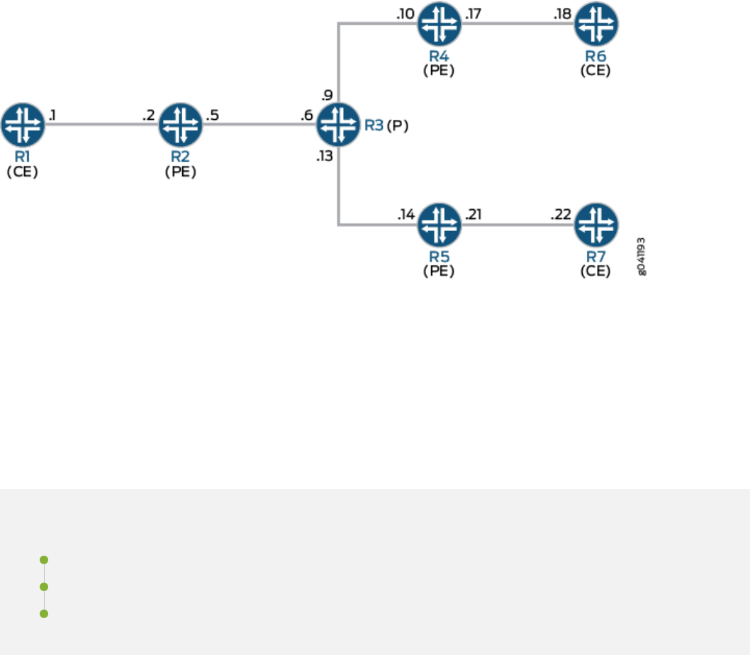
Figure 37: MBGP MVPN with BGP Route Flap Damping
On PE Device R4, BGP route ap damping is congured for address family inet-mvpn. A roung policy
called dampPolicy uses the nlri-route-type match condion to damp only MVPN route types 3, 4, and 5. All
other MVPN route types are not damped.
This example shows the full conguraon on all devices in the "CLI Quick Conguraon" on page 622
secon. The "Conguring Device R4" on page 627 secon shows the step-by-step conguraon for PE
Device R4.
Conguraon
IN THIS SECTION
CLI Quick Conguraon | 622
Conguring Device R4 | 627
Results | 630
CLI Quick Conguraon
To quickly congure this example, copy the following commands, paste them into a text le, remove any
line breaks, change any details necessary to match your network conguraon, and then copy and paste
the commands into the CLI at the [edit] hierarchy level.
622

Device R1
set interfaces ge-1/2/0 unit 1 family inet address 10.1.1.1/30
set interfaces ge-1/2/0 unit 1 family mpls
set interfaces lo0 unit 1 family inet address 172.16.1.1/32
set protocols ospf area 0.0.0.0 interface lo0.1 passive
set protocols ospf area 0.0.0.0 interface ge-1/2/0.1
set protocols pim rp static address 172.16.100.1
set protocols pim interface all
set routing-options router-id 172.16.1.1
Device R2
set interfaces ge-1/2/0 unit 2 family inet address 10.1.1.2/30
set interfaces ge-1/2/0 unit 2 family mpls
set interfaces ge-1/2/1 unit 5 family inet address 10.1.1.5/30
set interfaces ge-1/2/1 unit 5 family mpls
set interfaces vt-1/2/0 unit 2 family inet
set interfaces lo0 unit 2 family inet address 172.16.1.2/32
set interfaces lo0 unit 102 family inet address 172.16.100.1/32
set protocols mpls interface ge-1/2/1.5
set protocols bgp group ibgp type internal
set protocols bgp group ibgp local-address 172.16.1.2
set protocols bgp group ibgp family inet-vpn any
set protocols bgp group ibgp family inet-mvpn signaling
set protocols bgp group ibgp neighbor 172.16.1.4
set protocols bgp group ibgp neighbor 172.16.1.5
set protocols ospf area 0.0.0.0 interface lo0.2 passive
set protocols ospf area 0.0.0.0 interface ge-1/2/1.5
set protocols ldp interface ge-1/2/1.5
set protocols ldp p2mp
set policy-options policy-statement parent_vpn_routes from protocol bgp
set policy-options policy-statement parent_vpn_routes then accept
set routing-instances vpn-1 instance-type vrf
set routing-instances vpn-1 interface ge-1/2/0.2
set routing-instances vpn-1 interface vt-1/2/0.2
set routing-instances vpn-1 interface lo0.102
set routing-instances vpn-1 route-distinguisher 100:100
set routing-instances vpn-1 provider-tunnel ldp-p2mp
set routing-instances vpn-1 vrf-target target:1:1
set routing-instances vpn-1 protocols ospf export parent_vpn_routes
623

set routing-instances vpn-1 protocols ospf area 0.0.0.0 interface lo0.102 passive
set routing-instances vpn-1 protocols ospf area 0.0.0.0 interface ge-1/2/0.2
set routing-instances vpn-1 protocols pim rp static address 172.16.1.2 with 172.16.4.1100.1
set routing-instances vpn-1 protocols pim interface ge-1/2/0.2 mode sparse
set routing-instances vpn-1 protocols mvpn
set routing-options router-id 172.16.1.2
set routing-options autonomous-system 1001
Device R3
set interfaces ge-1/2/0 unit 6 family inet address 10.1.1.6/30
set interfaces ge-1/2/0 unit 6 family mpls
set interfaces ge-1/2/1 unit 9 family inet address 10.1.1.9/30
set interfaces ge-1/2/1 unit 9 family mpls
set interfaces ge-1/2/2 unit 13 family inet address 10.1.1.13/30
set interfaces ge-1/2/2 unit 13 family mpls
set interfaces lo0 unit 3 family inet address 172.16.1.3/32
set protocols mpls interface ge-1/2/0.6
set protocols mpls interface ge-1/2/1.9
set protocols mpls interface ge-1/2/2.13
set protocols ospf area 0.0.0.0 interface lo0.3 passive
set protocols ospf area 0.0.0.0 interface ge-1/2/0.6
set protocols ospf area 0.0.0.0 interface ge-1/2/1.9
set protocols ospf area 0.0.0.0 interface ge-1/2/2.13
set protocols ldp interface ge-1/2/0.6
set protocols ldp interface ge-1/2/1.9
set protocols ldp interface ge-1/2/2.13
set protocols ldp p2mp
set routing-options router-id 172.16.1.3
Device R4
set interfaces ge-1/2/0 unit 10 family inet address 10.1.1.10/30
set interfaces ge-1/2/0 unit 10 family mpls
set interfaces ge-1/2/1 unit 17 family inet address 10.1.1.17/30
set interfaces ge-1/2/1 unit 17 family mpls
set interfaces vt-1/2/0 unit 4 family inet
set interfaces lo0 unit 4 family inet address 172.16.1.4/32
set interfaces lo0 unit 104 family inet address 172.16.100.1/32
set protocols rsvp interface all aggregate
set protocols mpls interface all
624

set protocols mpls interface ge-1/2/0.10
set protocols bgp group ibgp type internal
set protocols bgp group ibgp local-address 172.16.1.4
set protocols bgp group ibgp family inet-vpn unicast
set protocols bgp group ibgp family inet-vpn any
set protocols bgp group ibgp family inet-mvpn signaling damping
set protocols bgp group ibgp neighbor 172.16.1.2 import dampPolicy
set protocols bgp group ibgp neighbor 172.16.1.5
set protocols ospf traffic-engineering
set protocols ospf area 0.0.0.0 interface all
set protocols ospf area 0.0.0.0 interface lo0.4 passive
set protocols ospf area 0.0.0.0 interface ge-1/2/0.10
set protocols ldp interface ge-1/2/0.10
set protocols ldp p2mp
set policy-options policy-statement dampPolicy term term1 from family inet-mvpn
set policy-options policy-statement dampPolicy term term1 from nlri-route-type 3
set policy-options policy-statement dampPolicy term term1 from nlri-route-type 4
set policy-options policy-statement dampPolicy term term1 from nlri-route-type 5
set policy-options policy-statement dampPolicy term term1 then accept
set policy-options policy-statement dampPolicy then damping no-damp
set policy-options policy-statement dampPolicy then accept
set policy-options policy-statement parent_vpn_routes from protocol bgp
set policy-options policy-statement parent_vpn_routes then accept
set policy-options damping no-damp disable
set routing-instances vpn-1 instance-type vrf
set routing-instances vpn-1 interface vt-1/2/0.4
set routing-instances vpn-1 interface ge-1/2/1.17
set routing-instances vpn-1 interface lo0.104
set routing-instances vpn-1 route-distinguisher 100:100
set routing-instances vpn-1 vrf-target target:1:1
set routing-instances vpn-1 protocols ospf export parent_vpn_routes
set routing-instances vpn-1 protocols ospf area 0.0.0.0 interface lo0.104 passive
set routing-instances vpn-1 protocols ospf area 0.0.0.0 interface ge-1/2/1.17
set routing-instances vpn-1 protocols pim rp static address 172.16.100.1
set routing-instances vpn-1 protocols pim interface ge-1/2/1.17 mode sparse
set routing-instances vpn-1 protocols mvpn
set routing-options router-id 172.16.1.4
set routing-options autonomous-system 64501
625

Device R5
set interfaces ge-1/2/0 unit 14 family inet address 10.1.1.14/30
set interfaces ge-1/2/0 unit 14 family mpls
set interfaces ge-1/2/1 unit 21 family inet address 10.1.1.21/30
set interfaces ge-1/2/1 unit 21 family mpls
set interfaces vt-1/2/0 unit 5 family inet
set interfaces lo0 unit 5 family inet address 172.16.1.5/32
set interfaces lo0 unit 105 family inet address 172.16.100.5/32
set protocols mpls interface ge-1/2/0.14
set protocols bgp group ibgp type internal
set protocols bgp group ibgp local-address 172.16.1.5
set protocols bgp group ibgp family inet-vpn any
set protocols bgp group ibgp family inet-mvpn signaling
set protocols bgp group ibgp neighbor 172.16.1.2
set protocols bgp group ibgp neighbor 172.16.1.4
set protocols ospf area 0.0.0.0 interface lo0.5 passive
set protocols ospf area 0.0.0.0 interface ge-1/2/0.14
set protocols ldp interface ge-1/2/0.14
set protocols ldp p2mp
set policy-options policy-statement parent_vpn_routes from protocol bgp
set policy-options policy-statement parent_vpn_routes then accept
set routing-instances vpn-1 instance-type vrf
set routing-instances vpn-1 interface vt-1/2/0.5
set routing-instances vpn-1 interface ge-1/2/1.21
set routing-instances vpn-1 interface lo0.105
set routing-instances vpn-1 route-distinguisher 100:100
set routing-instances vpn-1 vrf-target target:1:1
set routing-instances vpn-1 protocols ospf export parent_vpn_routes
set routing-instances vpn-1 protocols ospf area 0.0.0.0 interface lo0.105 passive
set routing-instances vpn-1 protocols ospf area 0.0.0.0 interface ge-1/2/1.21
set routing-instances vpn-1 protocols pim rp static address 172.16.100.2
set routing-instances vpn-1 protocols pim interface ge-1/2/1.21 mode sparse
set routing-instances vpn-1 protocols mvpn
set routing-options router-id 172.16.1.5
set routing-options autonomous-system 1001
Device R6
set interfaces ge-1/2/0 unit 18 family inet address 10.1.1.18/30
set interfaces ge-1/2/0 unit 18 family mpls
626

set interfaces lo0 unit 6 family inet address 172.16.1.6/32
set protocols sap listen 233.1.1.1
set protocols ospf area 0.0.0.0 interface lo0.6 passive
set protocols ospf area 0.0.0.0 interface ge-1/2/0.18
set protocols pim rp static address 172.16.100.2
set protocols pim interface all
set routing-options router-id 172.16.1.6
Device R7
set interfaces ge-1/2/0 unit 22 family inet address 10.1.1.22/30
set interfaces ge-1/2/0 unit 22 family mpls
set interfaces lo0 unit 7 family inet address 172.16.1.7/32
set protocols ospf area 0.0.0.0 interface lo0.7 passive
set protocols ospf area 0.0.0.0 interface ge-1/2/0.22
set protocols pim rp static address 172.16.100.2
set protocols pim interface all
set routing-options router-id 172.16.1.7
Conguring Device R4
Step-by-Step Procedure
The following example requires you to navigate various levels in the conguraon hierarchy. For
informaon about navigang the CLI, see
Using the CLI Editor in Conguraon Mode
in the Junos OS
CLI User Guide.
To congure Device R4:
1. Congure the interfaces.
[edit interfaces]
user@R4# set ge-1/2/0 unit 10 family inet address 10.1.1.10/30
user@R4# set ge-1/2/0 unit 10 family mpls
user@R4# set ge-1/2/1 unit 17 family inet address 10.1.1.17/30
user@R4# set ge-1/2/1 unit 17 family mpls
user@R4# set vt-1/2/0 unit 4 family inet
user@R4# set lo0 unit 4 family inet address 172.16.1.4/32
user@R4# set lo0 unit 104 family inet address 172.16.100.4/32
627

2. Congure MPLS and the signaling protocols on the interfaces.
[edit protocols]
user@R4# set mpls interface all
user@R4# set mpls interface ge-1/2/0.10
user@R4# set rsvp interface all aggregate
user@R4# set ldp interface ge-1/2/0.10
user@R4# set ldp p2mp
3. Congure BGP.
The BGP conguraon enables BGP route ap damping for the inet-mvpn address family. The BGP
conguraon also imports into the roung table the roung policy called dampPolicy. This policy is
applied to neighbor PE Device R2.
[edit protocols bgp group ibgp]
user@R4# set type internal
user@R4# set local-address 172.16.1.4
user@R4# set family inet-vpn unicast
user@R4# set family inet-vpn any
user@R4# set family inet-mvpn signaling damping
user@R4# set neighbor 172.16.1.2 import dampPolicy
user@R4# set neighbor 172.16.1.5
4. Congure an interior gateway protocol.
[edit protocols ospf]
user@R4# set traffic-engineering
[edit protocols ospf area 0.0.0.0]
user@R4# set interface all
user@R4# set interface lo0.4 passive
user@R4# set interface ge-1/2/0.10
5.
Congure a damping policy that uses the nlri-route-type match condion to damp only MVPN route
types 3, 4, and 5.
[edit policy-options policy-statement dampPolicy term term1]
user@R4# set from family inet-mvpn
user@R4# set from nlri-route-type 3
628

user@R4# set from nlri-route-type 4
user@R4# set from nlri-route-type 5
user@R4# set then accept
6. Congure the damping policy to disable BGP route ap damping.
The no-damp policy (damping no-damp disable) causes any damping state that is present in the roung
table to be deleted. The then damping no-damp statement applies the no-damp policy as an acon and has
no from match condions. Therefore, all routes that are not matched by term1 are matched by this
term, with the result that all other MVPN route types are not damped.
[edit policy-options policy-statement dampPolicy]
user@R4# set then damping no-damp
user@R4# set then accept
[edit policy-options]
user@R4# set damping no-damp disable
7. Congure the parent_vpn_routes to accept all other BGP routes that are not from the inet-mvpn address
family.
This policy is applied as an OSPF export policy in the roung instance.
[edit policy-options policy-statement parent_vpn_routes]
user@R4# set from protocol bgp
user@R4# set then accept
8. Congure the VPN roung and forwarding (VRF) instance.
[edit routing-instances vpn-1]
user@R4# set instance-type vrf
user@R4# set interface vt-1/2/0.4
user@R4# set interface ge-1/2/1.17
user@R4# set interface lo0.104
user@R4# set route-distinguisher 100:100
user@R4# set vrf-target target:1:1
user@R4# set protocols ospf export parent_vpn_routes
user@R4# set protocols ospf area 0.0.0.0 interface lo0.104 passive
user@R4# set protocols ospf area 0.0.0.0 interface ge-1/2/1.17
user@R4# set protocols pim rp static address 172.16.100.2
629

user@R4# set protocols pim interface ge-1/2/1.17 mode sparse
user@R4# set protocols mvpn
9. Congure the router ID and the autonomous system (AS) number.
[edit routing-options]
user@R4# set router-id 172.16.1.4
user@R4# set autonomous-system 1001
10. If you are done conguring the device, commit the conguraon.
user@R4# commit
Results
From conguraon mode, conrm your conguraon by entering the show interfaces, show protocols, show
policy-options, show routing-instances, and show routing-options commands. If the output does not display the
intended conguraon, repeat the instrucons in this example to correct the conguraon.
user@R4# show interfaces
ge-1/2/0 {
unit 10 {
family inet {
address 10.1.1.10/30;
}
family mpls;
}
}
ge-1/2/1 {
unit 17 {
family inet {
address 10.1.1.17/30;
}
family mpls;
}
}
vt-1/2/0 {
unit 4 {
family inet;
630

}
}
lo0 {
unit 4 {
family inet {
address 172.16.1.4/32;
}
}
unit 104 {
family inet {
address 172.16.100.4/32;
}
}
}
user@R4# show protocols
rsvp {
interface all {
aggregate;
}
}
mpls {
interface all;
interface ge-1/2/0.10;
}
bgp {
group ibgp {
type internal;
local-address 172.16.1.4;
family inet-vpn {
unicast;
any;
}
family inet-mvpn {
signaling {
damping;
}
}
neighbor 172.16.1.2 {
import dampPolicy;
}
631

neighbor 172.16.1.5;
}
}
ospf {
traffic-engineering;
area 0.0.0.0 {
interface all;
interface lo0.4 {
passive;
}
interface ge-1/2/0.10;
}
}
ldp {
interface ge-1/2/0.10;
p2mp;
}
user@R4# show policy-options
policy-statement dampPolicy {
term term1 {
from {
family inet-mvpn;
nlri-route-type [ 3 4 5 ];
}
then accept;
}
then {
damping no-damp;
accept;
}
}
policy-statement parent_vpn_routes {
from protocol bgp;
then accept;
}
damping no-damp {
632

disable;
}
user@R4# show routing-instances
vpn-1 {
instance-type vrf;
interface vt-1/2/0.4;
interface ge-1/2/1.17;
interface lo0.104;
route-distinguisher 100:100;
vrf-target target:1:1;
protocols {
ospf {
export parent_vpn_routes;
area 0.0.0.0 {
interface lo0.104 {
passive;
}
interface ge-1/2/1.17;
}
}
pim {
rp {
static {
address 172.16.100.2;
}
}
interface ge-1/2/1.17 {
mode sparse;
}
}
mvpn;
}
}
user@R4# show routing-optons
router-id 172.16.1.4;
autonomous-system 1001;
633

Vericaon
IN THIS SECTION
Verifying That Route Flap Damping Is Disabled | 634
Verifying Route Flap Damping | 635
Conrm that the conguraon is working properly.
Verifying That Route Flap Damping Is Disabled
Purpose
Verify the presence of the no-damp policy, which disables damping for MVPN route types other than 3, 4,
and 5.
Acon
From operaonal mode, enter the show policy damping command.
user@R4> show policy damping
Default damping information:
Halflife: 15 minutes
Reuse merit: 750 Suppress/cutoff merit: 3000
Maximum suppress time: 60 minutes
Computed values:
Merit ceiling: 12110
Maximum decay: 6193
Damping information for "no-damp":
Damping disabled
Meaning
The output shows that the default damping parameters are in eect and that the no-damp policy is also in
eect for the specied route types.
634

Verifying Route Flap Damping
Purpose
Check whether BGP routes have been damped.
Acon
From operaonal mode, enter the show bgp summary command.
user@R4> show bgp summary
Groups: 1 Peers: 2 Down peers: 0
Table Tot Paths Act Paths Suppressed History Damp State Pending
bgp.l3vpn.0
6 6 0 0 0 0
bgp.l3vpn.2
0 0 0 0 0 0
bgp.mvpn.0
2 2 0 0 0 0
Peer AS InPkt OutPkt OutQ Flaps Last Up/Dwn State|#Active/
Received/Accepted/Damped...
172.16.1.2 1001 3159 3155 0 0 23:43:47 Establ
bgp.l3vpn.0: 3/3/3/0
bgp.l3vpn.2: 0/0/0/0
bgp.mvpn.0: 1/1/1/0
vpn-1.inet.0: 3/3/3/0
vpn-1.mvpn.0: 1/1/1/0
172.16.1.5 1001 3157 3154 0 0 23:43:40 Establ
bgp.l3vpn.0: 3/3/3/0
bgp.l3vpn.2: 0/0/0/0
bgp.mvpn.0: 1/1/1/0
vpn-1.inet.0: 3/3/3/0
vpn-1.mvpn.0: 1/1/1/0
Meaning
The Damp State eld shows that zero routes in the bgp.mvpn.0 roung table have been damped.
Further down, the last number in the State eld shows that zero routes have been damped for BGP peer
172.16.1.2.
635


CHAPTER 8
Tracking Trac Usage with Source Class Usage and
Desnaon Class Usage Acons
IN THIS CHAPTER
Understanding Source Class Usage and Desnaon Class Usage Opons | 637
Source Class Usage Overview | 639
Guidelines for Conguring SCU | 640
System Requirements for SCU | 641
Terms and Acronyms for SCU | 642
Roadmap for Conguring SCU | 643
Roadmap for Conguring SCU with Layer 3 VPNs | 644
Conguring Route Filters and Source Classes in a Roung Policy | 644
Applying the Policy to the Forwarding Table | 646
Enabling Accounng on Inbound and Outbound Interfaces | 646
Conguring Input SCU on the vt Interface of the Egress PE Router | 647
Mapping the SCU-Enabled vt Interface to the VRF Instance | 648
Conguring SCU on the Output Interface | 649
Associang an Accounng Prole with SCU Classes | 650
Verifying Your SCU Accounng Prole | 651
SCU Conguraon | 652
SCU with Layer 3 VPNs Conguraon | 663
Example: Grouping Source and Desnaon Prexes into a Forwarding Class | 673
Understanding Source Class Usage and Desnaon Class Usage Opons
You can maintain packet counts based on the entry and exit points for trac passing through your
network. Entry and exit points are idened by source and desnaon prexes grouped into disjoint
637

sets dened as source classes and
desnaon classes
. You can dene classes based on a variety of
parameters, such as roung neighbors, autonomous systems, and route lters.
Source class usage (SCU) counts packets sent to customers by performing lookups on the IP source
address and the IP desnaon address. SCU makes it possible to track trac originang from specic
prexes on the provider core and desned for specic prexes on the customer edge. You must enable
SCU accounng on both the inbound and outbound physical interfaces.
Desnaon class usage (DCU) counts packets from customers by performing lookups of the
IP desnaon address. DCU makes it possible to track trac originang from the customer edge and
desned for specic prexes on the provider core router.
On T Series Core Routers and M320 Mulservice Edge Routers, the source class and desnaon classes
are not carried across the plaorm fabric. The implicaons of this are as follows:
• On T Series and M320 routers, SCU and DCU accounng is performed before the packet enters the
fabric.
• On T Series and M320 routers, DCU is performed before output lters are evaluated.
• On M Series plaorms, DCU is performed aer output lters are evaluated.
• If an output lter drops trac on M Series devices, the dropped packets are excluded from DCU
stascs.
• If an output lter drops trac on T Series and M320 routers, the dropped packets are included in
DCU stascs.
NOTE: For PTX Series routers with FPC3, and PTX1000 routers, to support SCU and DCU, you
must congure enhanced-mode on the chassis.
On MX Series plaorms with MPC/MIC interfaces, SCU and DCU are performed aer output lters are
evaluated. Packets dropped by output lters are not included in SCU or DCU stascs.
On MX Series plaorms with non-MPC/MIC interfaces, SCU and DCU are performed before output
lters are evaluated. Packets dropped by output lters are included in SCU and DCU stascs.
On PTX Series plaorms, SCU and DCU accounng is performed before output lters are evaluated.
Packets dropped by output lters are included in SCU and DCU stascs. On PTX10003, PTX10004,
PTX10008, PTX10001-36MR, and line card JNP10K-LC1201, the systems prexes with SCU and DCU
classes assigned occupy more space in the forwarding informaon base (FIB) tables than regular routes.
You must limit the number of prexes with non-default class assigned.
On Enhanced Scaling FPCs (T640-FPC1-ES, T640-FPC2-ES, T640-FPC3-ES, T640-FPC4-1P-ES , and
T1600-FPC4-ES), the source class accounng is performed at ingress. Starng with Junos OS Release
638

14.2, the SCU accounng is performed at ingress on a T4000 Type 5 FPC. The implicaons of this are as
follows:
• SCU accounng is performed when packets traverse from T4000 Type 5 FPC (ingress FPC) to
Enhanced Scaling FPCs (egress FPC).
• SCU accounng is performed when packets traverse from Enhanced Scaling FPCs (ingress FPC) to
T4000 Type 5 FPC (egress FPC).
NOTE: When the interface stascs are cleared and then the roung engine is replaced, the SCU
and DCU stascs will not match the stascs of the previous roung engine.
For more informaon about source class usage, see the Roung Policies, Firewall Filters, and Trac
Policers User Guide and the Junos OS Network Interfaces Library for Roung Devices.
Source Class Usage Overview
Source class usage (SCU) is a logical extension of the desnaon class usage (DCU) concept. DCU was
created so that Juniper Networks customers could count on a per-interface basis how much trac was
sent to specied prexes. Figure 38 on page 639 shows a service provider edge (PE) router diagram.
Figure 38: DCU/SCU Concept
The Fast Ethernet interfaces contain inbound trac from customers, and the SONET/SDH interfaces are
connected to outbound public network prexes. With DCU congured on the Fast Ethernet interfaces,
you can track how much trac is sent to a specic prex in the core of the network originang from one
of the specied interfaces (in this case, the Fast Ethernet interfaces).
However, DCU limits your ability to keep track of trac moving in the reverse direcon. It can account
for all trac that arrives on a core interface and heads toward a specic customer, but it cannot count
trac that arrives on a core interface from a specic prex. For example, DCU can process cumulave
639

trac headed toward interface fe-0/0/0, but cannot dierenate between trac coming only from
10.3.0.0/16 and trac coming from all prexes.
You can track source-based trac by using SCU, which allows you to monitor the amount of trac
originang from a specic prex. With this feature, usage can be tracked and customers can be billed for
the trac they receive.
RELATED DOCUMENTATION
System Requirements for SCU | 641
Roadmap for Conguring SCU | 643
Roadmap for Conguring SCU with Layer 3 VPNs | 644
SCU Conguraon | 652
SCU with Layer 3 VPNs Conguraon | 663
Guidelines for Conguring SCU
When you enable SCU or DCU, keep the following informaon in mind:
• In Junos OS Release 5.6 and later for M Series routers only, you can use a source class or a
desnaon class as a match condion in a
rewall lter
. To congure, include the desnaon-class or
source-class statement at the [edit firewall filter
firewall-name
term
term-name
from] hierarchy level. For
more informaon about rewall lters, see the
Junos Policy Framework Conguraon Guide
.
• You can assign up to 126 source classes and 126 desnaon classes.
• When conguring policy acon statements, you can congure only one source class for each
matching route. In other words, more than one source class cannot be applied to the same route.
• A source or desnaon class is applied to a packet only once during the roung table lookup. When a
network prex matches a class-usage policy, SCU is assigned to packets rst; DCU is assigned only if
SCU has not been assigned. Be careful when using both class types, since misconguraon can result
in uncounted packets. The following example explores one potenal mishap:
A packet arrives on a router interface congured for both SCU and DCU. The packet's source address
matches an SCU class, and its desnaon matches a DCU class. Consequently, the packet is
subjected to a source lookup and is marked with the SCU class. The DCU class is ignored. As a result,
the packet is forwarded to the outbound interface with only the SCU class sll intact.
However, the outbound interface lacks an SCU conguraon. When the packet is ready to leave the
router, the router detects that the output interface is not congured for SCU and the packet is not
640

counted by SCU. Likewise, even though the prex matched the DCU prex, the DCU counters do not
increment because DCU was superseded by SCU at the inbound interface.
To solve this problem, make sure you congure both the inbound and outbound interfaces completely or
congure only one class type per interface per direcon.
• Classes cannot be mapped to directly connected prexes congured on local interfaces. This is true
for DCU and SCU classes.
• If you use mulple terms within a single policy, you only need to congure the policy name and apply
it to the forwarding table once. This makes it easier to change opons within your terms without
having to recongure the main policy.
• Execute command line interface (CLI) show commands and accounng proles at the desired
outbound interface to track SCU trac. SCU counters increment at the SCU output interface.
• Apply your classes to the inbound and outbound interfaces by means of the input and output SCU
interface parameters.
• On M320 and T Series routers, the source and desnaon classes are not carried across the plaorm
fabric. For these routers, SCU and DCU accounng is performed before the packet enters the fabric
and DCU is performed before output lters are evaluated.
• If an output lter drops trac on M Series routers other than the M120 router and M320 router, the
dropped packets are excluded from DCU stascs. If an output lter drops trac on M320 and T
Series routers, the dropped packets are included in DCU stascs.
RELATED DOCUMENTATION
Source Class Usage Overview | 639
System Requirements for SCU | 641
Roadmap for Conguring SCU | 643
SCU Conguraon | 652
System Requirements for SCU
To implement SCU, your system must meet these requirements:
• Junos OS Release 8.2 or later for M120 and MX Series router support
• Junos OS Release 6.2 or later for IPv6 SCU
641

• Junos OS Release 5.6 or later to use a source class or a desnaon class as a match condion in a
rewall lter
• Junos OS Release 5.4 or later for IPv4 SCU
• Three Juniper Networks M Series, MX Series, or T Series routers for basic SCU and ve routers for
SCU with Layer 3 VPNs. One router acts as a source class usage transit router, and the other routers
are used to generate trac or parcipate in the Layer 3 VPN.
• For M Series and T Series routers, a Tunnel Services PIC for SCU with Layer 3 VPNs
RELATED DOCUMENTATION
Source Class Usage Overview | 639
Roadmap for Conguring SCU | 643
Roadmap for Conguring SCU with Layer 3 VPNs | 644
SCU Conguraon | 652
SCU with Layer 3 VPNs Conguraon | 663
Terms and Acronyms for SCU
IN THIS SECTION
desnaon class usage (DCU) | 642
source class usage (SCU) | 643
source address (SA) | 643
desnaon address (DA) | 643
desnaon class usage (DCU)
A method of grouping certain types of trac and monitoring these groups through CLI show commands,
accounng proles, or SNMP. DCU uses a desnaon address lookup when determining group
membership. For more informaon about DCU, see the
Junos Policy Framework Conguraon Guide
.
642

source class usage (SCU)
A method of grouping certain types of trac and monitoring these groups through CLI show commands,
accounng proles, or SNMP. SCU uses a source address lookup when determining group membership.
For more informaon about SCU, see the
Junos Policy Framework Conguraon Guide
.
source address (SA)
The IP address of a device sending a packet. This address is included in the IP header and is analyzed by
the router for a variety of services, including source-based ltering, policing, class of service (CoS), and
SCU.
desnaon address (DA)
The IP address of a device intended as the receiver for a packet. This address is included in the IP header
and is the main address analyzed by the router during roung table lookups and DCU.
Roadmap for Conguring SCU
To congure source class usage (SCU), you must:
1. Create a roung policy that includes prex route lters that indicate the IPv4 or IPv6 source
addresses to monitor. See "Conguring Route Filters and Source Classes in a Roung Policy" on page
644.
2. Apply the lters to the forwarding table. See "Applying the Policy to the Forwarding Table" on page
646.
3. Enable accounng on the inbound and outbound interfaces. See "Enabling Accounng on Inbound
and Outbound Interfaces" on page 646.
RELATED DOCUMENTATION
Source Class Usage Overview | 639
System Requirements for SCU | 641
SCU Conguraon | 652
643

Roadmap for Conguring SCU with Layer 3 VPNs
SCU can be implemented over regular interfaces; it is also used in combinaon with Layer 3 VPNs.
When you view SCU trac on an ingress provider edge (PE) router, use the standard procedure outlined
in "Roadmap for Conguring SCU" on page 643. However, when you enable packet counng for Layer 3
VPNs at the egress point of the MPLS tunnel, you need to take some addional steps, as follows:
1. Congure SCU on the virtual loopback tunnel (vt) interface of the egress PE router. See "Conguring
Input SCU on the vt Interface of the Egress PE Router" on page 647.
2. Map the SCU-enabled input interface of that router to the virtual roung and forwarding (VRF)
instance. See "Mapping the SCU-Enabled vt Interface to the VRF Instance" on page 648.
3. Congure SCU on the output interface of the egress router. See "Conguring SCU on the Output
Interface" on page 649.
4. Congure an accounng prole and associate the source class with that accounng prole. You can
also specify the lename for the data capture, a class usage prole name, and an interval indicang
how oen you want the SCU informaon to be saved. See "Associang an Accounng Prole with
SCU Classes" on page 650.
NOTE: SCU is not supported over Layer 2 VPNs.
RELATED DOCUMENTATION
Source Class Usage Overview | 639
System Requirements for SCU | 641
SCU with Layer 3 VPNs Conguraon | 663
Conguring Route Filters and Source Classes in a Roung Policy
Begin conguring SCU by creang prex route lters in a policy statement. These prexes indicate the
IPv4 or IPv6 source addresses to monitor. Within the policy statement, you must dene and name the
source classes aached to the lters.
[edit policy-options]
policy-statement
policy-name
{
644

term
term-name
{
from {
route-filter
address
/
prefix
;
}
then source-class
class-name
;
}
}
NOTE: When conguring policy acon statements, you can congure only one source class for
each matching route. In other words, more than one source class cannot be applied to the same
route.
An alternate conguraon method, using the forwarding-class policy acon, is even more exible. It
allows your IPv4 or IPv6 route lters to apply to an SCU prole, a DCU prole, or both simultaneously.
Addionally, if you have only one term, you can implement the from and then statements at the [edit
policy-options policy-statement
policy-name
] hierarchy level.
[edit policy-options]
policy-statement
policy-name
{
from {
route-filter 105.15.0.0/16 orlonger;
}
then forwarding-class
class-name
;
}
A third opon is the exisng DCU parameter of desnaon-class. For more informaon on DCU, see the
Junos Policy Framework Conguraon Guide
.
RELATED DOCUMENTATION
Source Class Usage Overview | 639
System Requirements for SCU | 641
Roadmap for Conguring SCU | 643
SCU Conguraon | 652
645

Applying the Policy to the Forwarding Table
Next, apply the policy you created to the forwarding table. When you apply the policy, the network
prexes you dened are marked with the appropriate source class.
[edit routing-options]
forwarding-table {
export
policy-name
;
}
RELATED DOCUMENTATION
Source Class Usage Overview | 639
System Requirements for SCU | 641
Roadmap for Conguring SCU | 643
SCU Conguraon | 652
Enabling Accounng on Inbound and Outbound Interfaces
Unlike DCU, which only requires implementaon on a single interface, accounng for SCU must be
enabled on two interfaces: the inbound and outbound physical or logical interfaces traversed by the
source class. You must dene explicitly the two interfaces on which SCU monitored trac is expected to
arrive and depart. This is because SCU performs two lookups in the roung table: a source address (SA)
and a desnaon address (DA) lookup. In contrast, DCU only has a single desnaon address lookup. By
specifying the addresses involved in the addional SCU SA lookup, you minimize the performance
impact on your router.
An individual SCU interface can be congured as an input interface, an output interface, or both. SCU
can be enabled in an IPv4 (family inet) or IPv6 (family inet6) network. To congure SCU accounng,
include the source-class-usage statement at the [edit interfaces
interface-name
unit
logical-unit-number
family
(inet | inet 6) accounting] hierarchy level:
[edit]
interfaces {
interface-name
{
unit
unit-number
{
family (inet | inet6) {
646

accounting {
source-class-usage {
(input | output | input output);
}
destination-class-usage;
}
}
}
}
}
Aer the full SCU conguraon is enabled, every packet arriving on an SCU input interface is subjected
to an SA-based lookup and then a DA-based lookup. In addion, an individual set of counters for every
congured SCU class is maintained by the router on a per-interface and per-protocol family basis.
RELATED DOCUMENTATION
Source Class Usage Overview | 639
System Requirements for SCU | 641
Roadmap for Conguring SCU | 643
SCU Conguraon | 652
Conguring Input SCU on the vt Interface of the Egress PE Router
To enable SCU in a Layer 3 VPN, congure source class usage on the virtual loopback tunnel (vt)
interface of the egress PE router that is either congured for or equipped with a Tunnel PIC. The
interface is equivalent to the inbound SCU interface, so use the input statement at the [edit interfaces
vt-
interface-number
unit 0 family inet accounting source-class-usage] hierarchy level:
[edit]
interfaces {
vt-0/3/0 {
unit 0 {
family inet {
accounting {
source-class-usage {
input;
}
647

}
}
}
}
}
RELATED DOCUMENTATION
Source Class Usage Overview | 639
System Requirements for SCU | 641
Roadmap for Conguring SCU with Layer 3 VPNs | 644
SCU with Layer 3 VPNs Conguraon | 663
Mapping the SCU-Enabled vt Interface to the VRF Instance
Next, include the VPN loopback tunnel interface in the desired VRF instance at the [edit routing-instances
routing-instance-name
] hierarchy level:
[edit]
routing-instances {
routing-instance-name
{
instance-type vrf;
interface at-2/1/1.0;
interface vt-0/3/0.0;
route-distinguisher 10.250.14.225:100;
vrf-import import-policy-name;
vrf-export export-policy-name;
protocols {
bgp {
group to-r4 {
local-address 10.20.253.1;
peer-as 400;
neighbor 10.20.253.2;
}
}
}
648

}
}
RELATED DOCUMENTATION
Source Class Usage Overview | 639
System Requirements for SCU | 641
Roadmap for Conguring SCU with Layer 3 VPNs | 644
SCU with Layer 3 VPNs Conguraon | 663
Conguring SCU on the Output Interface
Since VPN trac enters the egress router through the VPN loopback tunnel interface, you sll need to
determine the exit interface for this trac. To complete your SCU conguraon, congure the output
version of source class usage on the exit interface of your egress router:
[edit interfaces]
at-1/1/0 {
unit 0 {
family inet {
accounting {
source-class-usage {
output;
}
}
}
}
}
RELATED DOCUMENTATION
Source Class Usage Overview | 639
System Requirements for SCU | 641
Roadmap for Conguring SCU with Layer 3 VPNs | 644
SCU with Layer 3 VPNs Conguraon | 663
649

Associang an Accounng Prole with SCU Classes
Once your source classes are dened, implemented on the inbound and outbound interfaces, and
applied to the forwarding table, you are ready to associate the source class with an accounng prole.
Congure the accounng prole at the [edit accounting-options class-usage-profile] hierarchy level. You can
associate either an SCU source class or a DCU desnaon class with the accounng prole. You can also
specify the lename for the data capture, a class usage prole name, and an interval (in minutes)
indicang how oen you want the SCU informaon to be saved to the le.
[edit]
accounting-options {
file
filename
;
class-usage-profile
profile-name
{
file
filename
;
interval
minutes
;
source-classes {
source-class-name
;
}
destination-classes {
destination-class-name
;
}
}
}
NOTE: SCU accounng occurs on the outbound interface before output lter processing. If an
SCU-marked packet is discarded in the router, the SCU counters can indicate more trac than
actually exists. You must use lter counters or traceopons logs to ensure that all packets
dropped by the SCU lter are recorded. If logged, you can subtract the discarded packets from
the SCU counter tallies and calculate the true trac prole.
Because DCU accounng occurs aer the ltering process, DCU is unaected by this disclaimer.
RELATED DOCUMENTATION
Source Class Usage Overview | 639
System Requirements for SCU | 641
Roadmap for Conguring SCU with Layer 3 VPNs | 644
SCU with Layer 3 VPNs Conguraon | 663
650

Verifying Your SCU Accounng Prole
IN THIS SECTION
Purpose | 651
Acon | 651
Purpose
To view the results of the SCU accounng prole you created.
Acon
Navigate to the /var/log directory of your router. It should contain the designated class usage prole log.
The layout of an SCU prole looks like this:
profile_name,epoch-timestamp,interface-name,source-class-name,packet-count,
byte-count
An example of the actual output from a prole looks like this:
scu_profile,980313078,ge-1/0/0.0,gold,82,6888
scu_profile,980313078,ge-1/0/0.0,silver,164,13776
scu_profile,980313078,ge-1/0/0.0,bronze,0,0
scu_profile,980313678,ge-1/0/0.0,gold,82,6888
scu_profile,980313678,ge-1/0/0.0,silver,246,20664
scu_profile,980313678,ge-1/0/0.0,bronze,0,0
To view the parameters of your SCU accounng prole, you can use the show accounting-options class-
usage-profile
scu-profile-name
command.
RELATED DOCUMENTATION
Source Class Usage Overview | 639
System Requirements for SCU | 641
651

Associang an Accounng Prole with SCU Classes | 650
SCU Conguraon
IN THIS SECTION
Conguring SCU | 652
Verifying Your Work | 656
Conguring SCU
Figure 39: SCU Topology Diagram
Figure 39 on page 652 shows a basic SCU conguraon with three routers. Source routers A and B use
loopback addresses as the prexes to be monitored. Most of the conguraon tasks and actual
monitoring occurs on transit Router SCU.
Begin your conguraon on Router A. The loopback address on Router A contains the origin of the
prex that is to be assigned to source class A on Router SCU. However, no SCU processing happens on
this router. Therefore, congure Router A for basic OSPF roung and include your loopback interface
and interface so-0/0/2 in the OSPF process.
Router A:
[edit]
interfaces {
so-0/0/2 {
unit 0 {
652

family inet {
address 10.255.50.2/24;
}
}
}
lo0 {
unit 0 {
family inet {
address 10.255.192.10/32;
}
}
}
}
protocols {
ospf {
area 0.0.0.0 {
interface so-0/0/2.0;
interface lo0.0;
}
}
}
Router SCU handles the bulk of the acvity in this example. On Router SCU, enable source class usage
on the inbound and outbound interfaces at the [edit interfaces
interface-name
unit
unit-number
family inet
accounting] hierarchy level. Make sure you specify the expected trac: input, output, or, in this case,
both.
Next, congure a route lter policy statement that matches the prexes of the loopback addresses from
routers A and B. Include statements in the policy that classify packets from Router A in one group
named scu-class-a and packets from Router B in a second class named scu-class-b. Noce the ecient use
of a single policy containing mulple terms.
Last, apply the policy to the forwarding table.
Router SCU
[edit]
interfaces {
so-0/0/1 {
unit 0 {
family inet {
accounting {
source-class-usage {
653

input;
output;
}
}
address 10.255.50.1/24;
}
}
}
so-0/0/3 {
unit 0 {
family inet {
accounting {
source-class-usage {
input;
output;
}
}
address 10.255.10.3/24;
}
}
}
lo0 {
unit 0 {
family inet {
address 10.255.6.111/32;
}
}
}
}
protocols {
ospf {
area 0.0.0.0 {
interface so-0/0/1.0;
interface so-0/0/3.0;
}
}
}
routing-options {
forwarding-table {
export scu-policy;
}
}
policy-options {
654

policy-statement scu-policy {
term 0 {
from {
route-filter 10.255.192.0/24 orlonger;
}
then source-class scu-class-a;
}
term 1 {
from {
route-filter 10.255.165.0/24 orlonger;
}
then source-class scu-class-b;
}
}
}
Complete the conguraon tasks on Router B. Just as Router A provides a source prex, Router B’s
loopback address matches the prex assigned to scu-class-b on Router SCU. Again, no SCU processing
happens on this router, so congure Router B for basic OSPF roung and include your loopback
interface and interface so-0/0/4 in the OSPF process.
Router B:
[edit]
interfaces {
so-0/0/4 {
unit 0 {
family inet {
address 10.255.10.4/24;
}
}
}
lo0 {
unit 0 {
family inet {
address 10.255.165.226/32;
}
}
}
}
protocols {
ospf {
655

area 0.0.0.0 {
interface so-0/0/4.0;
interface lo0.0;
}
}
}
Verifying Your Work
To verify that SCU is funconing properly, use the following commands:
• show interfaces
interface-name
statistics
• show interfaces
interface-name
(extensive | detail)
• show route (extensive | detail)
• show interfaces source-class
source-class-name interface-name
• clear interface
interface-name
statistics
You should always verify SCU stascs at the outbound SCU interface on which you congured the
output statement. You can perform the following three steps to check the funconality of SCU:
1. Clear all counters on your SCU-enabled router and verify that they are empty.
2. Send a ping from one edge router to another edge router to generate SCU trac across the SCU-
enabled router.
3. Verify that the counters are incremenng correctly on the outbound interface.
The following secon shows the output of these commands as used with the conguraon example.
user@scu> clear interfaces statistics all
user@scu> show interfaces so-0/0/1.0 statistics
Logical interface so-0/0/1.0 (Index 4) (SNMP ifIndex 119)
Flags: Point-To-Point SNMP-Traps Encapsulation: PPP
Protocol inet, MTU: 4470
Source class Packets Bytes
scu-class-a 0 0
scu-class-b 0 0
Addresses, Flags: Is-Preferred Is-Primary
Destination: 10.255.50/24, Local: 10.255.50.1
656

user@scu> show interfaces so-0/0/3.0 statistics
Logical interface so-0/0/3.0 (Index 6) (SNMP ifIndex 113)
Flags: Point-To-Point SNMP-Traps Encapsulation: PPP
Protocol inet, MTU: 4470
Source class Packets Bytes
scu-class-a 0 0
scu-class-b 0 0
Addresses, Flags: Is-Preferred Is-Primary
Destination: 10.255.10/24, Local: 10.255.10.3
user@scu> show interfaces source-class scu-class-a so-0/0/3.0
Protocol inet
Source class Packets Bytes
scu-class-a 0 0
user@scu> show interfaces source-class scu-class-b so-0/0/1.0
Protocol inet
Source class Packets Bytes
scu-class-b 0 0
user@routerB> ping 10.255.192.10 source 10.255.165.226 rapid 10000
user@routerA> ping 10.255.165.226 source 10.255.192.10 rapid 10000
user@scu> show interfaces source-class scu-class-a so-0/0/3.0
Protocol inet
Source class Packets Bytes
scu-class-a 20000 1680000
user@scu> show interfaces source-class scu-class-a so-0/0/1.0
Protocol inet
Source class Packets Bytes
scu-class-b 20000 1680000
user@scu> show interfaces so-0/0/3.0 statistics
Logical interface so-0/0/3.0 (Index 6) (SNMP ifIndex 113)
Flags: Point-To-Point SNMP-Traps Encapsulation: PPP
Protocol inet, MTU: 4470
Source class Packets Bytes
scu-class-a 20000 1680000
scu-class-b 0 0
Addresses, Flags: Is-Preferred Is-Primary
657

Destination: 10.255.10/24, Local: 10.255.10.3
user@scu> show interfaces so-0/0/1.0 statistics
Logical interface so-0/0/1.0 (Index 4) (SNMP ifIndex 119)
Flags: Point-To-Point SNMP-Traps Encapsulation: PPP
Protocol inet, MTU: 4470
Source class Packets Bytes
scu-class-a 0 0
scu-class-b 20000 1680000
Addresses, Flags: Is-Preferred Is-Primary
Destination: 10.255.50/24, Local: 10.255.50.1
user@scu> show route extensive 10.255.192.0
inet.0: 26 destinations, 28 routes (25 active, 0 holddown, 1 hidden)
10.255.192.0/18 (1 entry, 1 announced)
TSI:
KRT in-kernel 10.255.192.0/18 -> {so-0/0/1.0}
Source class: scu-class-a
*OSPF Preference: 150
Next hop: via so-0/0/1.0, selected
State: <Active Int Ext>
Age: 2:49:31 Metric: 0 Tag: 0
Task: OSPF
Announcement bits (1): 0-KRT
AS path: I
user@scu> show route extensive 10.255.165.0
inet.0: 26 destinations, 28 routes (25 active, 0 holddown, 1 hidden)
10.255.165.0/20 (1 entry, 1 announced)
TSI:
KRT in-kernel 10.255.165.0/20 -> {so-0/0/3.0}
Source class: scu-class-b
*OSPF Preference: 150
Next hop: via so-0/0/3.0, selected
State: <Active Int Ext>
Age: 2:49:31 Metric: 0 Tag: 0
658

Task: OSPF
Announcement bits (1): 0-KRT
AS path: I
user@scu> show interfaces so-0/0/1 detail
Physical interface: so-0/0/1, Enabled, Physical link is Up
Interface index: 12, SNMP ifIndex: 17, Generation: 11
Link-level type: PPP, MTU: 4474, Clocking: Internal, SONET mode, Speed: OC3,
Loopback: None, FCS: 16, Payload scrambler: Enabled
Device flags : Present Running
Interface flags: Point-To-Point SNMP-Traps
Link flags : Keepalives
Hold-times : Up 0 ms, Down 0 ms
Keepalive settings: Interval 10 seconds, Up-count 1, Down-count 3
Keepalive statistics:
Input : 46 (last seen 00:00:01 ago)
Output: 45 (last sent 00:00:00 ago)
LCP state: Opened
NCP state: inet: Opened, inet6: Not-configured, iso: Not-configured, mpls:
Not-configured
CHAP state: Not-configured
Last flapped : 2002-04-19 11:49:22 PDT (03:10:09 ago)
Statistics last cleared: 2002-04-19 14:52:04 PDT (00:07:27 ago)
Traffic statistics:
Input bytes : 1689276 40 bps
Output bytes : 1689747 48 bps
Input packets: 20197 0 pps
Output packets: 20200 0 pps
Queue counters: Queued packets Transmitted packets Dropped packets
0 best-effort 20053 20053 0
1 expedited-fo 0 0 0
2 assured-forw 0 0 0
3 network-cont 146 146 0
SONET alarms : None
SONET defects : None
Logical interface so-0/0/1.0 (Index 4) (SNMP ifIndex 119) (Generation 3)
Flags: Point-To-Point SNMP-Traps Encapsulation: PPP
Protocol inet, MTU: 4470
Flags: SCU-in, SCU-out
Generation: 6 Route table: 0
659

Source class Packets Bytes
scu-class-a 0 0
scu-class-b 20000 1680000
Filters: Input: icmp-so-0/0/1.0-i, Output: icmp-so-0/0/1.0-o
Addresses, Flags: Is-Preferred Is-Primary
Destination: 10.255.50/24, Local: 10.255.50.1, Broadcast: Unspecified,
Generation: 8
user@scu> show interfaces so-0/0/1 extensive
Physical interface: so-0/0/1, Enabled, Physical link is Up
Interface index: 12, SNMP ifIndex: 17, Generation: 11
Link-level type: PPP, MTU: 4474, Clocking: Internal, SONET mode, Speed: OC3,
Loopback: None, FCS: 16, Payload scrambler: Enabled
Device flags : Present Running
Interface flags: Point-To-Point SNMP-Traps
Link flags : Keepalives
Hold-times : Up 0 ms, Down 0 ms
Keepalive settings: Interval 10 seconds, Up-count 1, Down-count 3
Keepalive statistics:
Input : 51 (last seen 00:00:04 ago)
Output: 50 (last sent 00:00:05 ago)
LCP state: Opened
NCP state: inet: Opened, inet6: Not-configured, iso: Not-configured, mpls:
Not-configured
CHAP state: Not-configured
Last flapped : 2002-04-19 11:49:22 PDT (03:11:05 ago)
Statistics last cleared: 2002-04-19 14:52:04 PDT (00:08:23 ago)
Traffic statistics:
Input bytes : 1689884 264 bps
Output bytes : 1690388 280 bps
Input packets: 20215 0 pps
Output packets: 20217 0 pps
Input errors:
Errors: 0, Drops: 0, Framing errors: 0, Runts: 0, Giants: 0,
Bucket drops: 0, Policed discards: 0, L3 incompletes: 0,
L2 channel errors: 0, L2 mismatch timeouts: 0, HS link CRC errors: 0,
HS link FIFO overflows: 0
Output errors:
Carrier transitions: 0, Errors: 0, Drops: 0, Aged packets: 0,
HS link FIFO underflows: 0
Queue counters: Queued packets Transmitted packets Dropped packets
0 best-effort 20053 20053 0
1 expedited-fo 0 0 0
660

2 assured-forw 0 0 0
3 network-cont 164 164 0
SONET alarms : None
SONET defects : None
SONET PHY: Seconds Count State
PLL Lock 0 0 OK
PHY Light 0 0 OK
SONET section:
BIP-B1 0 0
SEF 0 0 OK
LOS 0 0 OK
LOF 0 0 OK
ES-S 0
SES-S 0
SEFS-S 0
SONET line:
BIP-B2 0 0
REI-L 0 0
RDI-L 0 0 OK
AIS-L 0 0 OK
BERR-SF 0 0 OK
BERR-SD 0 0 OK
ES-L 0
SES-L 0
UAS-L 0
ES-LFE 0
SES-LFE 0
UAS-LFE 0
SONET path:
BIP-B3 0 0
REI-P 0 0
LOP-P 0 0 OK
AIS-P 0 0 OK
RDI-P 0 0 OK
UNEQ-P 0 0 OK
PLM-P 0 0 OK
ES-P 0
SES-P 0
UAS-P 0
ES-PFE 0
SES-PFE 0
UAS-PFE 0
Received SONET overhead:
661

F1 : 0x00, J0 : 0x00, K1 : 0x00, K2 : 0x00
S1 : 0x00, C2 : 0xcf, C2(cmp) : 0xcf, F2 : 0x00
Z3 : 0x00, Z4 : 0x00, S1(cmp) : 0x00, V5 : 0x00
V5(cmp) : 0x00
Transmitted SONET overhead:
F1 : 0x00, J0 : 0x01, K1 : 0x00, K2 : 0x00
S1 : 0x00, C2 : 0xcf, F2 : 0x00, Z3 : 0x00
Z4 : 0x00, V5 : 0x00
Received path trace: e so-0/0/1
65 20 73 6f 2d 30 2f 30 2f 31 00 00 00 00 00 00 e so-0/0/1......
00 00 00 00 00 00 00 00 00 00 00 00 00 00 00 00 ................
00 00 00 00 00 00 00 00 00 00 00 00 00 00 00 00 ................
00 00 00 00 00 00 00 00 00 00 00 00 00 00 0d 0a ................
Transmitted path trace: scu so-0/0/1
67 68 62 20 73 6f 2d 30 2f 30 2f 31 00 00 00 00 scu so-0/0/1....
00 00 00 00 00 00 00 00 00 00 00 00 00 00 00 00 ................
00 00 00 00 00 00 00 00 00 00 00 00 00 00 00 00 ................
00 00 00 00 00 00 00 00 00 00 00 00 00 00 00 00 ................
HDLC configuration:
Policing bucket: Disabled
Shaping bucket : Disabled
Giant threshold: 4484, Runt threshold: 3
Packet Forwarding Engine configuration:
Destination slot: 0, PLP byte: 1 (0x00)
CoS transmit queue Bandwidth Buffer Priority Limit
% bps % bytes
0 best-effort 0 0 0 0 low none
1 expedited-forwarding 0 0 0 0 low none
2 assured-forwarding 0 0 0 0 low none
3 network-control 0 0 0 0 low none
Logical interface so-0/0/1.0 (Index 4) (SNMP ifIndex 119) (Generation 3)
Flags: Point-To-Point SNMP-Traps Encapsulation: PPP
Protocol inet, MTU: 4470
Flags: SCU-in, SCU-out
Generation: 6 Route table: 0
Source class Packets Bytes
scu-class-a 0 0
scu-class-b 20000 1680000
Filters: Input: icmp-so-0/0/1.0-i, Output: icmp-so-0/0/1.0-o
Addresses, Flags: Is-Preferred Is-Primary
Destination: 10.255.50/24, Local: 10.255.50.1, Broadcast: Unspecified,
Generation: 8
662

RELATED DOCUMENTATION
Source Class Usage Overview | 639
System Requirements for SCU | 641
Roadmap for Conguring SCU | 643
SCU with Layer 3 VPNs Conguraon
IN THIS SECTION
Conguring SCU in a Layer 3 VPN | 663
Verifying Your Work | 672
Conguring SCU in a Layer 3 VPN
Figure 40: SCU in a Layer 3 VPN Topology Diagram
Figure 40 on page 663 displays a Layer 3 VPN topology. CE1 and CE2 are customer edge (CE) routers
connected by a VPN through provider routers PE1, P0, and PE2. EBGP is established between routers
CE1 and PE1, IBGP connects routers PE1 and PE2 over an IS-IS/MPLS/LDP core, and a second EBGP
connecon ows between routers PE2 and CE2.
On Router CE1, begin your VPN by seng up an EBGP connecon to PE1. Install a stac route of
10.114.1.0/24 and adverse this route to your EBGP neighbor.
663

Router CE1
[edit]
interfaces {
ge-0/0/0 {
unit 0 {
family inet {
address 10.20.250.1/30;
}
}
}
}
routing-options {
static {
route 10.114.1.0/24 reject;
}
autonomous-system 100;
}
protocols {
bgp {
group to-pe1 {
local-address 10.20.250.1;
export inject-direct;
peer-as 300;
neighbor 10.20.250.2;
}
}
}
policy-options {
policy-statement inject-direct {
term 1 {
from {
protocol static;
route-filter 10.114.1.0/24 exact;
}
then accept;
}
term 2 {
from protocol direct;
then accept;
}
664

}
}
On PE1, complete the EBGP connecon to CE1 through a VRF roung instance. Set an export policy for
your VRF instance that puts BGP trac into a community, and an import policy that accepts like
community trac from your VPN neighbor. Lastly, congure an IBGP relaonship to Router PE2 that
runs over an IS-IS, MPLS, and LDP core.
Router PE1
[edit]
interfaces {
ge-0/0/1 {
unit 0 {
family inet {
address 10.20.250.2/30;
}
}
}
so-0/2/1 {
unit 0 {
family inet {
address 10.20.251.1/30;
}
family iso;
family mpls;
}
}
lo0 {
unit 0 {
family inet {
address 10.250.245.245/32;
}
family iso;
family mpls;
}
}
}
routing-options {
autonomous-system 300;
}
protocols {
665

mpls {
interface so-0/2/1;
}
bgp {
group ibgp {
type internal;
local-address 10.250.245.245;
family inet-vpn {
unicast;
}
neighbor 10.250.71.14;
}
}
isis {
interface so-0/2/1;
}
ldp {
interface so-0/2/1;
}
}
policy-options {
policy-statement red-import {
from {
protocol bgp;
community red-com;
}
then accept;
}
policy-statement red-export {
from protocol bgp;
then {
community add red-com;
accept;
}
}
community red-com members target:20:20;
}
routing-instances {
red {
instance-type vrf;
interface ge-0/0/1.0;
route-distinguisher 10.250.245.245:100;
vrf-import red-import;
666

vrf-export red-export;
protocols {
bgp {
group to-ce1 {
local-address 10.20.250.2;
peer-as 100;
neighbor 10.20.250.1;
}
}
}
}
}
On P0, connect the IBGP neighbors located at PE1 and PE2. Remember to include VPN-related
protocols (MPLS, LDP, and IGP) on all interfaces.
Router P0
[edit]
interfaces {
so-0/1/0 {
unit 0 {
family inet {
address 10.20.252.1/30;
}
family iso;
family mpls;
}
}
so-0/2/0 {
unit 0 {
family inet {
address 10.20.251.2/30;
}
family iso;
family mpls;
}
}
lo0 {
unit 0 {
family inet {
address 10.250.245.246/32;
667

}
family iso;
family mpls;
}
}
}
routing-options {
autonomous-system 300;
}
protocols {
mpls {
interface so-0/1/0;
interface so-0/2/0;
}
isis {
interface all;
}
ldp {
interface all;
}
}
On PE2, complete the IBGP relaonship to Router PE1. Establish an EBGP connecon to CE2 through a
VRF roung instance. Set an export policy for the VRF instance that places BGP trac into a
community, and an import policy that accepts like community trac from the VPN neighbor. Next,
establish a policy that adds the stac route from CE1 to a source class called GOLD1. Also, export this SCU
policy into the forwarding table. Finally, set your vt interface as the SCU input interface and establish the
CE-facing interface so-0/0/0 as the SCU output interface.
Router PE2
[edit]
interfaces {
so-0/1/1 {
unit 0 {
family inet {
address 10.20.252.2/30;
}
family iso;
family mpls;
}
}
668

so-0/0/0 {
unit 0 {
family inet {
accounting {
source-class-usage {
output;
}
}
address 10.20.253.1/30;
}
}
}
vt-4/1/0 {
unit 0 {
family inet {
accounting {
source-class-usage {
input;
}
}
address 10.250.71.14/32;
}
family iso;
family mpls;
}
}
}
routing-options {
autonomous-system 300;
forwarding-table {
export inject-customer2-dest-class;
}
}
protocols {
mpls {
interface so-0/1/1;
interface vt-4/1/0;
}
bgp {
group ibgp {
type internal;
local-address 10.250.71.14;
family inet-vpn {
669

unicast;
}
neighbor 10.250.245.245;
}
}
isis {
interface so-0/1/1;
}
ldp {
interface so-0/1/1;
}
}
routing-instances {
red {
instance-type vrf;
interface so-0/0/0.0;
interface vt-4/1/0.0;
route-distinguisher 10.250.71.14:100;
vrf-import red-import;
vrf-export red-export;
protocols {
bgp {
group to-ce2 {
local-address 10.20.253.1;
peer-as 400;
neighbor 10.20.253.2;
}
}
}
}
}
policy-options {
policy-statement red-import {
from {
protocol bgp;
community red-com;
}
then accept;
}
policy-statement red-export {
from protocol bgp;
then {
community add red-com;
670

accept;
}
}
policy-statement inject-customer2-dest-class {
term term-gold1-traffic {
from {
route-filter 10.114.1.0/24 exact;
}
then source-class GOLD1;
}
}
community red-com members target:20:20;
}
On Router CE2, complete the VPN path by nishing the EBGP connecon to PE2.
Router CE2
[edit]
interfaces {
so-0/0/1 {
unit 0 {
family inet {
address 10.20.253.2/30;
}
}
}
}
routing-options {
autonomous-system 400;
}
protocols {
bgp {
group to-pe2 {
local-address 10.20.253.2;
export inject-direct;
peer-as 300;
neighbor 10.20.253.1;
}
}
}
policy-options {
671

policy-statement inject-direct {
from {
protocol direct;
}
then accept;
}
}
Verifying Your Work
To verify that SCU is funconing properly in the Layer 3 VPN, use the following commands:
• show interfaces
interface-name
statistics
• show interfaces source-class
source-class-name interface-name
• show interfaces
interface-name
(extensive | detail)
• show route (extensive | detail)
• clear interface
interface-name
statistics
You should always verify SCU stascs at the outbound SCU interface on which you congured the
output statement. To check SCU funconality, follow these steps:
1. Clear all counters on your SCU-enabled router and verify they are empty.
2. Send a ping from the ingress CE router to the second CE router to generate SCU trac across the
SCU-enabled VPN route.
3. Verify that the counters are incremenng correctly on the outbound interface.
The following secon shows the output of these commands used with the conguraon example.
user@pe2> clear interfaces statistics all
user@pe2> show interfaces so-0/0/0.0 statistics
Logical interface so-0/0/0.0 (Index 6) (SNMP ifIndex 113)
Flags: Point-To-Point SNMP-Traps Encapsulation: PPP
Protocol inet, MTU: 4470
Source class Packets Bytes
GOLD1 0 0
Addresses, Flags: Is-Preferred Is-Primary
672

user@pe2> show interfaces source-class GOLD1 so-0/0/0.0
Protocol inet
Source class Packets Bytes
GOLD1 0 0
user@ce1> ping 10.20.253.2 source 10.114.1.1 rapid count 10000
user@scu> show interfaces source-class GOLD1 so-0/0/0.0
Protocol inet
Source class Packets Bytes
GOLD1 20000 1680000
user@scu> show interfaces so-0/0/0.0 statistics
Logical interface so-0/0/0.0 (Index 6) (SNMP ifIndex 113)
Flags: Point-To-Point SNMP-Traps Encapsulation: PPP
Protocol inet, MTU: 4470
Source class Packets Bytes
GOLD1 20000 1680000
Addresses, Flags: Is-Preferred Is-Primary
Destination: 10.20.253/24, Local: 10.20.253.1
RELATED DOCUMENTATION
Source Class Usage Overview | 639
System Requirements for SCU | 641
Example: Grouping Source and Desnaon Prexes into a Forwarding
Class
IN THIS SECTION
Requirements | 674
Overview | 674
Conguraon | 677
Vericaon | 684
673
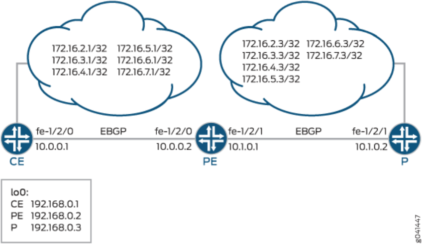
This example shows how to group source and desnaon prexes into a forwarding class.
Requirements
No special conguraon beyond device inializaon is required before conguring this example.
Overview
This example uses three roung devices: a customer edge (CE) device, a provider edge (PE) device, and a
provider core (P) device.
Figure 41 on page 674 shows the sample network.
Figure 41: SCU and DCU Sample Network
Source class usage (SCU) counts packets sent to the customer edge by performing lookup on the IP
source address and the IP desnaon address. SCU makes it possible to track trac originang from
specic prexes on the provider core and desned for specic prexes on the customer edge.
DCU counts packets from customers by performing a lookup of the IP desnaon address. DCU makes
it possible to track trac originang from the customer edge and desned for specic prexes on the
provider core router.
On Device PE’s fe-1/2/1 interface, facing the provider core (represented by Device P), SCU input is
congured with the
source-class-usage input
statement to track trac originang at Device P and desned
674

to Device CE. On this same interface, the destination-class-usage input statement is congured to track
trac originang at Device CE desned to the provider core.
user@PE# show interfaces fe-1/2/1 unit 0 family inet
accounting {
source-class-usage {
input; # tracks traffic destined to customer edge
}
destination-class-usage; # tracks traffic destined to provider core
}
address 10.1.0.1/30;
Unlike desnaon class usage (DCU), which only requires implementaon on a single interface,
accounng for SCU must be enabled on two interfaces: the inbound and outbound interfaces traversed
by the source class. You must dene explicitly the two interfaces on which SCU monitored trac is
expected to arrive and depart. This is because SCU performs two lookups in the roung table: a source
address (SA) and a desnaon address (DA) lookup. In contrast, DCU only has a single desnaon
address lookup.
On Device PE’s fe-1/2/0 interface, facing Device CE, SCU output is congured with the source-class-
usage output statement.
user@PE# show interfaces fe-1/2/0 unit 0 family inet
accounting {
source-class-usage {
output;
}
}
address 10.0.0.2/30;
To account for trac desned to the customer, the policy called scu_class uses route lters to place
trac into the gold1, gold2, and gold3 classes.
user@PE# show policy-options
policy-statement scu_class {
term gold1 {
from {
route-filter 172.16.2.0/24 orlonger;
}
then source-class gold1;
}
675

term gold2 {
from {
route-filter 172.16.3.0/24 orlonger;
}
then source-class gold2;
}
term gold3 {
from {
route-filter 172.16.4.0/24 orlonger;
}
then source-class gold3;
}
}
To account for trac desned to the provider, the policy called dcu_class uses route lters to place
trac into the silver1, silver2, and silver3 classes.
user@PE# show policy-options
policy-statement dcu_class {
term silver1 {
from {
route-filter 172.16.5.0/24 orlonger;
}
then destination-class silver1;
}
term silver2 {
from {
route-filter 172.16.6.0/24 orlonger;
}
then destination-class silver2;
}
term silver3 {
from {
route-filter 172.16.7.0/24 orlonger;
}
then destination-class silver3;
}
}
676

The policies are then applied to the forwarding table.
forwarding-table {
export [ dcu_class scu_class ];
}
The example uses stac routes to provide connecvity and loopback interface addresses for tesng the
operaon.
"CLI Quick Conguraon" on page 677 shows the conguraon for all of the devices in Figure 41 on
page 674.
The secon "No Link Title" on page 680 describes the steps on Device PE.
Conguraon
IN THIS SECTION
Procedure | 677
Procedure
CLI Quick Conguraon
To quickly congure this example, copy the following commands, paste them into a text le, remove any
line breaks, change any details necessary to match your network conguraon, and then copy and paste
the commands into the CLI at the [edit] hierarchy level.
Device CE
set interfaces fe-1/2/0 unit 0 family inet address 10.0.0.1/30
set interfaces lo0 unit 0 family inet address 192.168.0.1/32
set interfaces lo0 unit 0 family inet address 172.16.0.1/32
set interfaces lo0 unit 0 family inet address 172.16.0.1/32
set interfaces lo0 unit 0 family inet address 172.16.0.1/32
set interfaces lo0 unit 0 family inet address 172.16.0.1/32
set interfaces lo0 unit 0 family inet address 172.16.0.1/32
set interfaces lo0 unit 0 family inet address 172.16.0.1/32
set protocols bgp group ext type external
677

set protocols bgp group ext export send-direct
set protocols bgp group ext export send-static
set protocols bgp group ext peer-as 200
set protocols bgp group ext neighbor 10.0.0.2
set policy-options policy-statement send-direct term 1 from protocol direct
set policy-options policy-statement send-direct term 1 then accept
set policy-options policy-statement send-static term 1 from protocol static
set policy-options policy-statement send-static term 1 then accept
set routing-options static route 10.1.0.0/30 next-hop 10.0.0.2
set routing-options autonomous-system 100
Device PE
set interfaces fe-1/2/0 unit 0 family inet accounting source-class-usage output
set interfaces fe-1/2/0 unit 0 family inet address 10.0.0.2/30
set interfaces fe-1/2/1 unit 0 family inet accounting source-class-usage input
set interfaces fe-1/2/1 unit 0 family inet accounting destination-class-usage
set interfaces fe-1/2/1 unit 0 family inet address 10.1.0.1/30
set interfaces lo0 unit 0 family inet address 192.168.0.2/32
set protocols bgp group ext type external
set protocols bgp group ext export send-direct
set protocols bgp group ext neighbor 10.0.0.1 peer-as 100
set protocols bgp group ext neighbor 10.1.0.2 peer-as 300
set policy-options policy-statement dcu_class term silver1 from route-filter 172.16.5.0/24
orlonger
set policy-options policy-statement dcu_class term silver1 then destination-class silver1
set policy-options policy-statement dcu_class term silver2 from route-filter 172.16.6.0/24
orlonger
set policy-options policy-statement dcu_class term silver2 then destination-class silver2
set policy-options policy-statement dcu_class term silver3 from route-filter 172.16.7.0/24
orlonger
set policy-options policy-statement dcu_class term silver3 then destination-class silver3
set policy-options policy-statement scu_class term gold1 from route-filter 172.16.2.0/24 orlonger
set policy-options policy-statement scu_class term gold1 then source-class gold1
set policy-options policy-statement scu_class term gold2 from route-filter 172.16.3.0/24 orlonger
set policy-options policy-statement scu_class term gold2 then source-class gold2
set policy-options policy-statement scu_class term gold3 from route-filter 172.16.4.0/24 orlonger
set policy-options policy-statement scu_class term gold3 then source-class gold3
set policy-options policy-statement send-direct term 1 from protocol direct
set policy-options policy-statement send-direct term 1 then accept
set routing-options autonomous-system 200
678

set routing-options forwarding-table export dcu_class
set routing-options forwarding-table export scu_class
Device P
set interfaces fe-1/2/1 unit 0 family inet address 10.1.0.2/30
set interfaces lo0 unit 0 family inet address 192.168.0.3/32
set interfaces lo0 unit 0 family inet address 172.16.0.3/32
set interfaces lo0 unit 0 family inet address 172.16.0.3/32
set interfaces lo0 unit 0 family inet address 172.16.0.3/32
set interfaces lo0 unit 0 family inet address 172.16.0.3/32
set interfaces lo0 unit 0 family inet address 172.16.0.3/32
set interfaces lo0 unit 0 family inet address 172.16.0.3/32
set protocols bgp group ext type external
set protocols bgp group ext export send-direct
set protocols bgp group ext export send-static
set protocols bgp group ext peer-as 200
set protocols bgp group ext neighbor 10.1.0.1
set policy-options policy-statement send-direct term 1 from protocol direct
set policy-options policy-statement send-direct term 1 then accept
set policy-options policy-statement send-static term 1 from protocol static
set policy-options policy-statement send-static term 1 then accept
set routing-options static route 10.0.0.0/30 next-hop 10.1.0.1
set routing-options static route 172.16.2.0/24 discard
set routing-options static route 172.16.3.0/24 discard
set routing-options static route 172.16.4.0/24 discard
set routing-options static route 172.16.5.0/24 discard
set routing-options static route 172.16.6.0/24 discard
set routing-options static route 172.16.7.0/24 discard
set routing-options autonomous-system 300
Step-by-Step Procedure
The following example requires you to navigate various levels in the conguraon hierarchy. For
instrucons on how to do that, see "Use the CLI Editor in Conguraon Mode" on page 1892 in the
Junos OS CLI User Guide.
To group source and desnaon prexes in a forwarding class:
679

1. Create the router interfaces.
[edit interfaces]
user@PE# set fe-1/2/0 unit 0 family inet accounting source-class-usage output
user@PE# set fe-1/2/0 unit 0 family inet address 10.0.0.2/30
user@PE# set fe-1/2/1 unit 0 family inet accounting source-class-usage input
user@PE# set fe-1/2/1 unit 0 family inet accounting destination-class-usage
user@PE# set fe-1/2/1 unit 0 family inet address 10.1.0.1/30
user@PE# set lo0 unit 0 family inet address 192.168.0.2/32
2. Congure BGP.
[edit protocols bgp group ext]
user@PE# set type external
user@PE# set export send-direct
user@PE# set neighbor 10.0.0.1 peer-as 100
user@PE# set neighbor 10.1.0.2 peer-as 300
3. Congure the DCU policy.
[edit policy-options policy-statement dcu_class]
user@PE# set term silver1 from route-filter 172.16.5.0/24 orlonger
user@PE# set term silver1 then destination-class silver1
user@PE# set term silver2 from route-filter 172.16.6.0/24 orlonger
user@PE# set term silver2 then destination-class silver2
user@PE# set term silver3 from route-filter 172.16.7.0/24 orlonger
user@PE# set term silver3 then destination-class silver3
4. Congure the SCU policy.
[edit policy-options policy-statement scu_class]
user@PE# set term gold1 from route-filter 172.16.2.0/24 orlonger
user@PE# set term gold1 then source-class gold1
user@PE# set term gold2 from route-filter 172.16.3.0/24 orlonger
user@PE# set term gold2 then source-class gold2
user@PE# set term gold3 from route-filter 172.16.4.0/24 orlonger
user@PE# set term gold3 then source-class gold3
680

5. Apply the policies to the forwarding table.
[edit routing-options forwarding-table]
user@PE# set export dcu_class
user@PE# set export scu_class
NOTE: You can refer to the same roung policy one or more mes in the same or dierent
export statement.
6. (Oponal) Congure a roung policy that adverses direct routes.
[edit policy-options policy-statement send-direct term 1]
user@PE# set from protocol direct
user@PE# set then accept
7. Congure the autonomous system (AS) number.
[edit routing-options]
user@PE# set autonomous-system 200
Results
From conguraon mode, conrm your conguraon by issuing the show interfaces, show protocols, show
policy-options, and show routing-options commands. If the output does not display the intended
conguraon, repeat the instrucons in this example to correct the conguraon.
user@PE# show interfaces
fe-1/2/0 {
unit 0 {
family inet {
accounting {
source-class-usage {
output;
}
}
address 10.0.0.2/30;
}
681

}
}
fe-1/2/1 {
unit 0 {
family inet {
accounting {
source-class-usage {
input;
}
destination-class-usage;
}
address 10.1.0.1/30;
}
}
}
lo0 {
unit 0 {
family inet {
address 192.168.0.2/32;
}
}
}
user@PE# show protocols
bgp {
group ext {
type external;
export send-direct;
neighbor 10.0.0.1 {
peer-as 100;
}
neighbor 10.1.0.2 {
peer-as 300;
}
}
}
user@PE# show policy-options
policy-statement dcu_class {
term silver1 {
682

from {
route-filter 172.16.5.0/24 orlonger;
}
then destination-class silver1;
}
term silver2 {
from {
route-filter 172.16.6.0/24 orlonger;
}
then destination-class silver2;
}
term silver3 {
from {
route-filter 172.16.7.0/24 orlonger;
}
then destination-class silver3;
}
}
policy-statement scu_class {
term gold1 {
from {
route-filter 172.16.2.0/24 orlonger;
}
then source-class gold1;
}
term gold2 {
from {
route-filter 172.16.3.0/24 orlonger;
}
then source-class gold2;
}
term gold3 {
from {
route-filter 172.16.4.0/24 orlonger;
}
then source-class gold3;
}
}
policy-statement send-direct {
term 1 {
from protocol direct;
then accept;
683

}
}
user@PE# show routing-options
autonomous-system 200;
forwarding-table {
export [ dcu_class scu_class ];
}
If you are done conguring the device, enter commit from conguraon mode.
Vericaon
IN THIS SECTION
Making Sure That the DCU Policy Is Working | 684
Making Sure That the SCU Policy Is Working | 685
Conrm that the conguraon is working properly.
Making Sure That the DCU Policy Is Working
Purpose
Verify that trac sent from the provider core into the customer network is causing the DCU policy
counters to increment.
Acon
1. From Device P, ping an address in the customer network.
user@P> ping rapid count 10000000 172.16.0.1
PING 172.16.0.1 (6.0.0.1): 56 data bytes
!!!!!!!!!!!!!!!!!!!!!!!!!!!!!!!!!!!!!!!!!!!!!!!!!!!!!!!!!!!!!!!!!!!!!!!!!!!!!!!!!!!!!!!!!!!!!!
!!!!!!!!!!!!
684

2. On Device PE, check the interface stascs on the interface facing the provider core.
user@PE> show interfaces statistics fe-1/2/1.0
Logical interface fe-1/2/1.0 (Index 108) (SNMP ifIndex 546)
Flags: SNMP-Traps 0x4000 Encapsulation: ENET2
Input packets : 251956
Output packets: 251961
Protocol inet, MTU: 1500
Flags: Sendbcast-pkt-to-re, DCU, SCU-in
Packets Bytes
Destination class (packet-per-second) (bits-per-second)
silver1 7460 626640
( 0) ( 0)
silver2 22440 2401416
( 256) ( 171963)
silver3 9004 756336
( 0) ( 0)
Addresses, Flags: Is-Preferred Is-Primary
Destination: 10.1.0.0/30, Local: 10.1.0.1, Broadcast: 10.1.0.3
Meaning
Packet and bit rates are displayed with packet and byte counters.
Alternavely, you can use the show interfaces destination-class all command to display the same
informaon.
Making Sure That the SCU Policy Is Working
Purpose
Verify that trac sent from the customer network into the provider core is causing the SCU policy
counters to increment.
685

Acon
1. From Device CE, ping an address in the customer network.
user@CE> ping rapid count 10000000 172.16.0.1
PING 172.16.0.1 (6.0.0.1): 56 data bytes
!!!!!!!!!!!!!!!!!!!!!!!!!!!!!!!!!!!!!!!!!!!!!!!!!!!!!!!!!!!!!!!!!!!!!!!!!!!!!!!!!!!!!!!!!!!!!!
!!!!!!!!!!!!!!!!!!!!!!!!!!!!!!!!!!!!!!!!!!!!!!!!!!!!!!!!!!!!!!!!!!!!!!!!!!!!!!!!!!!!!!!!!!!!!!
!!!!!!!!!!!!!!!!!!!!!!!!!!!!!!!!!!!!!!!!!!!!!!!!!!!!!!!!!!!!!!!!!!!!!!!!!!!!!!!!!!!!!!!!!!!!!!
!!!!!!!!!!!!!!!!!!!!!!!!!!!!!!!!!!!!!!!!!!!!!!!!!!!!!!!!!!!!!!!!!!!!!!!!!!!!!!!!!!!!!!!!!!!!!!
!!!!!!!!!!!!!!!!!!!!!!!!!!!!!!!!!!!!!!!!!!!!!!!!!!!!!!!!!!!!!!!!!!!!!!!!!!!!!!!!!!!!!!!!!!!!!!
!!!!!!!!!!!!!!!!!!!!!!!!!!!!!!!!!!!!!!!!!!!!!!!!!!!!!!!!!!!!!!!!!!!!!!!!!!!!!!!!!!!!!!!!!!!!!!
!!!!!!!!!!!!!!!!!!!!!!!!!!!!!!!!!!!!!!!!!!!!!!!!!!!!!!!!!!!!!!!!!!!!!!!!!!!!!!!!!!!!!!!!!!!!!!
!!!!!!!!!!!!!!!!!!!!!!!!!!!!!!!!!!!!!!!!!!!!!!!!!!!!!!!!!!!!!!!!!!!!!!!!!!!!!!!!!!!!!!!!!!!!!!
!!!!!!!!!!!!!!!!!!!!!!!!!!!!!!!!!!!!!!!!!!!!!!!!!!!!!!!!!!!!!!!!!!!!!!!!!!!!!!!!!!!!!!!!!!!!!!
!!!!!!!!!!!!!!!!!!!!!!!!!!!!!!!!!!!!!!!!!!!!!!!!!!!!!!!!!!!!!!!!!!!!!!!!!!!!!!!!!!!!!!!!!!!!!!
!!!!!!!!!!!!!!!!!!!!!!!!!!!!!!!!!!!!!!!!!!!!!!!!!!!!!!!!!!!!!!!!!!!!!!!!!!!!!!!!!!!!!!!!!!!!!!
!!!!!!!!!!
2. On Device PE, check the interface stascs on the interface facing the customer network.
user@PE> show interfaces statistics fe-1/2/0.0
Logical interface fe-1/2/0.0 (Index 93) (SNMP ifIndex 554)
Flags: SNMP-Traps 0x4000 Encapsulation: ENET2
Input packets : 32246
Output packets: 32245
Protocol inet, MTU: 1500
Flags: Sendbcast-pkt-to-re, Is-Primary, SCU-out
Packets Bytes
Source class (packet-per-second) (bits-per-second)
gold1 8871 745164
( 259) ( 174497)
gold2 1812 152208
( 0) ( 0)
gold3 5711 479724
( 0) ( 0)
686

Addresses, Flags: Is-Preferred Is-Primary
Destination: 10.0.0.0/30, Local: 10.0.0.2, Broadcast: 10.0.0.3
Meaning
Packet and bit rates are displayed with packet and byte counters.
Alternavely, you can use the show interfaces source-class all command to display the same informaon.
RELATED DOCUMENTATION
Route Filter Match Condions | 72
Understanding Source Class Usage and Desnaon Class Usage Opons
687

CHAPTER 9
Avoiding Trac Roung Threats with Condional
Roung Policies
IN THIS CHAPTER
Condional Adversement and Import Policy (Roung Table) with certain match condions | 688
Condional Adversement Enabling Condional Installaon of Prexes Use Cases | 691
Example: Conguring a Roung Policy for Condional Adversement Enabling Condional Installaon of
Prexes in a Roung Table | 693
Condional Adversement and Import Policy (Roung Table) with certain
match condions
BGP accepts all non-looped routes learned from neighbors and imports them into the RIB-In table. If
these routes are accepted by the BGP import policy, they are then imported into the inet.0 roung table.
In cases where only certain routes are required to be imported, provisions can be made such that the
peer roung device exports routes based on a condion or a set of condions.
The condion for exporng a route can be based on:
• The peer the route was learned from
• The interface the route was learned on
• Some other required aribute
For example:
[edit]
policy-options {
condition
condition-name
{
if-route-exists address table
table-name
;
688

}
}
This is known as condional installaon of prexes and is described in
Example: Conguring a Roung
Policy for Condional Adversement Enabling Condional Installaon of Prexes in a Roung Table
.
Condions in roung policies can be congured irrespecve of whether they are a part of the export or
import policies or both. The export policy supports these condions inherited from the roung policy
based on the existence of another route in the roung policy. However, the import policy doesn't
support these condions, and the condions are not executed even if they are present.
Figure 42 on page 689 illustrates where BGP import and export policies are applied. An import policy is
applied to inbound routes that are visible in the output of the show route receive-protocol bgp
neighbor-
address
command. An export policy is applied to outbound routes that are visible in the output of the show
route advertising-protocol bgp
neighbor-address
command.
Figure 42: BGP Import and Export Policies
To enable condional installaon of prexes, an export policy must be congured on the device where
the prex export has to take place. The export policy evaluates each route to verify that it sases all
the match condions under the from statement. It also searches for the existence of the route dened
under the condition statement (also congured under the from statement).
If the route does not match the enre set of required condions dened in the policy, or if the route
dened under the condition statement does not exist in the roung table, the route is not exported to its
BGP peers. Thus, a condional export policy matches the routes for the desired route or prex you want
installed in the peers’ roung table.
To congure the condional installaon of prexes with the help of an export policy:
689

1. Create a condition statement to check prexes.
[edit]
policy-options {
condition
condition-name
{
if-route-exists address table
table-name
;
}
}
2. Create an export policy with the newly created condion using the condition statement.
[edit]
policy-options {
policy-statement
policy-name
{
term 1 {
from {
protocols bgp;
condition
condition-name
;
}
then {
accept;
}
}
}
}
3. Apply the export policy to the device that requires only selected prexes to be exported from the
roung table.
[edit]
protocols bgp {
group
group-name
{
export
policy-name
;
}
}
690

RELATED DOCUMENTATION
Condional Adversement Enabling Condional Installaon of Prexes Use Cases
Condional Adversement Enabling Condional Installaon of Prexes
Use Cases
Networks are usually subdivided into smaller, more-manageable units called autonomous systems (ASs).
When BGP is used by routers to form peer relaonships in the same AS, it is referred to as internal BGP
(IBGP). When BGP is used by routers to form peer relaonships in dierent ASs, it is referred to as
external BGP (EBGP).
Aer performing route sanity checks, a BGP router accepts the routes received from its peers and
installs them into the roung table. By default, all routers in IBGP and EBGP sessions follow the
standard BGP adversement rules. While a router in an IBGP session adverses only the routes learned
from its direct peers, a router in an EBGP session adverses all routes learned from its direct and
indirect peers (peers of peers). Hence, in a typical network congured with EBGP, a router adds all
routes received from an EBGP peer into its roung table and adverses nearly all routes to all EBGP
peers.
A service provider exchanging BGP routes with both customers and peers on the Internet is at risk of
malicious and unintended threats that can compromise the proper roung of trac, as well as the
operaon of the routers.
This has several disadvantages:
• Non-aggregated route adversements—A customer could erroneously adverse all its prexes to the
ISP rather than an aggregate of its address space. Given the size of the Internet roung table, this
must be carefully controlled. An edge router might also need only a default route out toward the
Internet and instead be receiving the enre BGP roung table from its upstream peer.
• BGP route manipulaon—If a malicious administrator alters the contents of the BGP roung table, it
could prevent trac from reaching its intended desnaon.
• BGP route hijacking—A rogue administrator of a BGP peer could maliciously announce a network’s
prexes in an aempt to reroute the trac intended for the vicm network to the administrator’s
network to either gain access to the contents of trac or to block the vicm’s online services.
• BGP denial of service (DoS)—If a malicious administrator sends unexpected or undesirable BGP
trac to a router in an aempt to use all of the router’s available BGP resources, it might result in
impairing the router’s ability to process valid BGP route informaon.
Condional installaon of prexes can be used to address all the problems previously menoned. If a
customer requires access to remote networks, it is possible to install a specic route in the roung table
691

of the router that is connected with the remote network. This does not happen in a typical EBGP
network and hence, condional installaon of prexes becomes essenal.
ASs are not only bound by physical relaonships but by business or other organizaonal relaonships.
An AS can provide services to another organizaon, or act as a transit AS between two other ASs. These
transit ASs are bound by contractual agreements between the pares that include parameters on how to
connect to each other and most importantly, the type and quanty of trac they carry for each other.
Therefore, for both legal and nancial reasons, service providers must implement policies that control
how BGP routes are exchanged with neighbors, which routes are accepted from those neighbors, and
how those routes aect the trac between the ASs.
There are many dierent opons available to lter routes received from a BGP peer to both enforce
inter-AS policies and migate the risks of receiving potenally harmful routes. Convenonal route
ltering examines the aributes of a route and accepts or rejects the route based on such aributes. A
policy or lter can examine the contents of the AS-Path, the next-hop value, a community value, a list of
prexes, the address family of the route, and so on.
In some cases, the standard “acceptance condion” of matching a parcular aribute value is not
enough. The service provider might need to use another condion outside of the route itself, for
example, another route in the roung table. As an example, it might be desirable to install a default route
received from an upstream peer, only if it can be veried that this peer has reachability to other
networks further upstream. This condional route installaon avoids installing a default route that is
used to send trac toward this peer, when the peer might have lost its routes upstream, leading to
black-holed trac. To achieve this, the router can be congured to search for the presence of a
parcular route in the roung table, and based on this knowledge accept or reject another prex.
Example: Conguring a Roung Policy for Condional Adversement Enabling Condional Installaon
of Prexes in a Roung Table
explains how the condional installaon of prexes can be congured and
veried.
RELATED DOCUMENTATION
Example: Conguring a Roung Policy for Condional Adversement Enabling Condional
Installaon of Prexes in a Roung Table
692

Example: Conguring a Roung Policy for Condional Adversement
Enabling Condional Installaon of Prexes in a Roung Table
IN THIS SECTION
Requirements | 693
Overview | 693
Conguraon | 697
Vericaon | 707
This example shows how to
congure condional installaon of prexes in a roung table using BGP
export policy.
Requirements
This example uses the following hardware and soware components:
• M Series Mulservice Edge Routers, MX Series 5G Universal Roung Plaorms, or T Series Core
Routers
• Junos OS Release 9.0 or later
Overview
IN THIS SECTION
Topology | 697
In this example, three routers in three dierent autonomous systems (ASs) are connected and congured
with the BGP protocol. The router labeled Internet, which is the upstream router, has ve addresses
congured on its lo0.0 loopback interface (172.16.11.1/32, 172.16.12.1/32, 172.16.13.1/32,
172.16.14.1/32, and 172.16.15.1/32), and an extra loopback address (192.168.9.1/32) is congured as
the router ID. These six addresses are exported into BGP to emulate the contents of a BGP roung table
of a router connected to the Internet, and adversed to North.
693

The North and South routers use the 10.0.89.12/30 and 10.0.78.12/30 networks, respecvely, and use
192.168.7.1 and 192.168.8.1 for their respecve loopback addresses.
Figure 43 on page 694 shows the topology used in this example.
Figure 43: Condional Installaon of Prexes
Router North exports the 172.16.0.0/16 BGP routes it learns from Router Internet to Router South.
These routes might represent the routes owned by the Internet router's domain. In addion, when the
specic 172.16.11.1/32 route is present, Router North also adverses a default route. The 172.16.11.1
route might represent the Internet router's link to a er 1 transit peering provider that provides full
internet connecvity.
Router South receives all six routes, but should only install the default route and one other specic route
(172.16.11.1/32) in its roung table.
To summarize, the example meets the following requirements:
• On North, send all 172.16/16 prexes. In addion, also send 0/0 to South only if a parcular route is
present in the inet.0 roung table (in this example 172.16.11.1/32).
• On South, accept and install the default route and the 172.16.11.1/32 route in the roung and
forwarding tables. Drop all other routes. Consider that South might be a lower-end device that
cannot accept a full Internet roung table. As a result the operator only wants South to have the
default route and one other specic prex.
694

The rst requirement is met with an export policy on North:
user@North# show policy-options
policy-statement conditional-export-bgp {
term prefix_11 {
from {
protocol bgp;
route-filter 172.16.0.0/16 orlonger;
}
then accept;
}
term conditional-default {
from {
route-filter 0.0.0.0/0 exact;
condition prefix_11;
}
then accept;
}
term others {
then reject;
}
}
condition prefix_11 {
if-route-exists {
172.16.11.1/32;
table inet.0;
}
}
The logic of the condional export policy can be summarized as follows: If 0/0 is present, and if
172.16.11.1/32 is present, then send the 0/0 prex. This implies that if 172.16.11.1/32 is not present,
then do not send 0/0.
The second requirement is met with an import policy on South:
user@South# show policy-options
policy-statement import-selected-routes {
term 1 {
from {
rib inet.0;
neighbor 10.0.78.14;
route-filter 0.0.0.0/0 exact;
695

route-filter 172.16.11.1/32 exact;
}
then accept;
}
term 2 {
then reject;
}
}
In this example, four routes are dropped as a result of the import policy on South. This is because the
export policy on North leaks all of the routes received from Internet, and the import policy on South
excludes some of these routes.
It is important to understand that in Junos OS, although an import policy (inbound route lter) might
reject a route, not use it for trac forwarding, and not include it in an adversement to other peers, the
router retains these routes as hidden routes. These hidden routes are not available for policy or roung
purposes. However, they do occupy memory space on the router. A service provider ltering routes to
control the amount of informaon being kept in memory and processed by a router might want the
router to enrely drop the routes being rejected by the import policy.
Hidden routes can be viewed by using the show route receive-protocol bgp
neighbor-address
hidden command.
The hidden routes can then be retained or dropped from the roung table by conguring the keep all |
none statement at the [edit protocols bgp] or [edit protocols bgp group
group-name
] hierarchy level.
The rules of BGP route retenon are as follows:
• By default, all routes learned from BGP are retained, except those where the AS path is looped. (The
AS path includes the local AS.)
• By conguring the keep all statement, all routes learned from BGP are retained, even those with the
local AS in the AS path.
• By conguring the keep none statement, BGP discards routes that were received from a peer and that
were rejected by import policy or other sanity checking. When this statement is congured and the
inbound policy changes, Junos OS re-adverses all the routes adversed by the peer.
When you congure keep all or keep none and the peers support route refresh, the local speaker sends a
refresh message and performs an import evaluaon. For these peers, the sessions do not restart. To
determine if a peer supports refresh, check for Peer supports Refresh capability in the output of the show bgp
neighbor command.
CAUTION: If you congure keep all or keep none and the peer does not support session
restart, the associated BGP sessions are restarted (apped).
696

Topology
Conguraon
IN THIS SECTION
CLI Quick Conguraon | 697
Conguring Condional Installaon of Prexes | 699
Results | 703
CLI Quick
Conguraon
To quickly congure this example, copy the following commands, paste them into a text le, remove any
line breaks, change any details necessary to match your network conguraon, and then copy and paste
the commands into the CLI at the [edit] hierarchy level.
Router Internet
set interfaces lo0 unit 0 family inet address 172.16.11.1/32
set interfaces lo0 unit 0 family inet address 172.16.12.1/32
set interfaces lo0 unit 0 family inet address 172.16.13.1/32
set interfaces lo0 unit 0 family inet address 172.16.14.1/32
set interfaces lo0 unit 0 family inet address 172.16.15.1/32
set interfaces lo0 unit 0 family inet address 192.168.9.1/32
set interfaces fe-0/1/3 unit 0 family inet address 10.0.89.14/30
set protocols bgp group toNorth local-address 10.0.89.14
set protocols bgp group toNorth peer-as 65200
set protocols bgp group toNorth neighbor 10.0.89.13
set protocols bgp group toNorth export into-bgp
set policy-options policy-statement into-bgp term 1 from interface lo0.0
set policy-options policy-statement into-bgp term 1 then accept
set routing-options router-id 192.168.9.1
set routing-options autonomous-system 65300
697

Router North
set interfaces fe-1/3/1 unit 0 family inet address 10.0.78.14/30
set interfaces fe-1/3/0 unit 0 family inet address 10.0.89.13/30
set interfaces lo0 unit 0 family inet address 192.168.8.1/32
set protocols bgp group toInternet local-address 10.0.89.13
set protocols bgp group toInternet peer-as 65300
set protocols bgp group toInternet neighbor 10.0.89.14
set protocols bgp group toSouth local-address 10.0.78.14
set protocols bgp group toSouth export conditional-export-bgp
set protocols bgp group toSouth peer-as 65100
set protocols bgp group toSouth neighbor 10.0.78.13
set policy-options policy-statement conditional-export-bgp term prefix_11 from protocol bgp
set policy-options policy-statement conditional-export-bgp term prefix_11 from route-filter
172.16.0.0/16 orlonger
set policy-options policy-statement conditional-export-bgp term prefix_11 then accept
set policy-options policy-statement conditional-export-bgp term conditional-default from route-
filter 0.0.0.0/0 exact
set policy-options policy-statement conditional-export-bgp term conditional-default from
condition prefix_11
set policy-options policy-statement conditional-export-bgp term conditional-default then accept
set policy-options policy-statement conditional-export-bgp term others then reject
set policy-options condition prefix_11 if-route-exists 172.16.11.1/32
set policy-options condition prefix_11 if-route-exists table inet.0
set routing-options static route 0/0 reject
set routing-options router-id 192.168.8.1
set routing-options autonomous-system 65200
Router South
set interfaces fe-0/1/2 unit 0 family inet address 10.0.78.13/30
set interfaces lo0 unit 0 family inet address 192.168.7.1/32
set protocols bgp group toNorth local-address 10.0.78.13
set protocols bgp group toNorth import import-selected-routes
set protocols bgp group toNorth peer-as 65200
set protocols bgp group toNorth neighbor 10.0.78.14
set policy-options policy-statement import-selected-routes term 1 from neighbor 10.0.78.14
set policy-options policy-statement import-selected-routes term 1 from route-filter
172.16.11.1/32 exact
set policy-options policy-statement import-selected-routes term 1 from route-filter 0.0.0.0/0
exact
698

set policy-options policy-statement import-selected-routes term 1 then accept
set policy-options policy-statement import-selected-routes term 2 then reject
set routing-options router-id 192.168.7.1
set routing-options autonomous-system 65100
Conguring Condional Installaon of Prexes
Step-by-Step Procedure
The following example requires that you navigate various levels in the conguraon hierarchy. For
informaon about navigang the CLI, see
Using the CLI Editor in Conguraon Mode
in the Junos OS
CLI User Guide.
To congure condional installaon of prexes:
1. Congure the router interfaces forming the links between the three routers.
Router Internet
[edit interfaces]
user@Internet# set fe-0/1/3 unit 0 family inet address 10.0.89.14/30
Router North
[edit interfaces]
user@North# set fe-1/3/1 unit 0 family inet address 10.0.78.14/30
user@North# set fe-1/3/0 unit 0 family inet address 10.0.89.13/30
Router South
[edit interfaces]
user@South# set fe-0/1/2 unit 0 family inet address 10.0.78.13/30
2. Congure ve loopback interface addresses on Router Internet to emulate BGP routes learned from
the Internet that are to be imported into the roung table of Router South, and congure an
addional address (192.168.9.1/32) that will be congured as the router ID.
Router Internet
[edit interfaces lo0 unit 0 family inet]
user@Internet# set address 172.16.11.1/32
user@Internet# set address 172.16.12.1/32
699

user@Internet# set address 172.16.13.1/32
user@Internet# set address 172.16.14.1/32
user@Internet# set address 172.16.15.1/32
user@Internet# set address 192.168.9.1/32
Also, congure the loopback interface addresses on Routers North and South.
Router North
[edit interfaces lo0 unit 0 family inet]
user@North# set address 192.168.8.1/32
Router South
[edit interfaces lo0 unit 0 family inet]
user@South# set address 192.168.7.1/32
3. Congure the stac default route on Router North to be adversed to Router South.
[edit routing-options]
user@North# set static route 0/0 reject
4. Dene the condion for exporng prexes from the roung table on Router North.
[edit policy-options condition prefix_11]
user@North# set if-route-exists 172.16.11.1/32
user@North# set if-route-exists table inet.0
5. Dene export policies (into-bgp and conditional-export-bgp ) on Routers Internet and North respecvely,
to adverse routes to BGP.
NOTE: Ensure that you reference the condion, prefix_11 (congured in Step "4" on page 700),
in the export policy.
Router Internet
[edit policy-options policy-statement into-bgp ]
700

user@Internet# set term 1 from interface lo0.0
user@Internet# set term 1 then accept
Router North
[edit policy-options policy-statement conditional-export-bgp]
user@North# set term prefix_11 from protocol bgp
user@North# set term prefix_11 from route-filter 172,16.0.0/16 orlonger
user@North# set term prefix_11 then accept
user@North# set term conditional-default from route-filter 0.0.0.0/0 exact
user@North# set term conditional-default from condition prefix_11
user@North# set term conditional-default then accept
user@North# set term others then reject
6. Dene an import policy (import-selected-routes) on Router South to import some of the routes
adversed by Router North into its roung table.
[edit policy-options policy-statement import-selected-routes ]
user@South# set term 1 from neighbor 10.0.78.14
user@South# set term 1 from route-filter 172.16.11.1/32 exact
user@South# set term 1 from route-filter 0.0.0.0/0 exact
user@South# set term 1 then accept
user@South# set term 2 then reject
7. Congure BGP on all three routers to enable the ow of prexes between the autonomous systems.
NOTE: Ensure that you apply the dened import and export policies to the respecve BGP
groups for prex adversement to take place.
Router Internet
[edit protocols bgp group toNorth]
user@Internet# set local-address 10.0.89.14
user@Internet# set peer-as 65200
701

user@Internet# set neighbor 10.0.89.13
user@Internet# set export into-bgp
Router North
[edit protocols bgp group toInternet]
user@North# set local-address 10.0.89.13
user@North# set peer-as 65300
user@North# set neighbor 10.0.89.14
[edit protocols bgp group toSouth]
user@North# set local-address 10.0.78.14
user@North# set peer-as 65100
user@North# set neighbor 10.0.78.13
user@North# set export conditional-export-bgp
Router South
[edit protocols bgp group toNorth]
user@South# set local-address 10.0.78.13
user@South# set peer-as 65200
user@South# set neighbor 10.0.78.14
user@South# set import import-selected-routes
8. Congure the router ID and autonomous system number for all three routers.
NOTE: In this example, the router ID is congured based on the IP address congured on the
lo0.0 interface of the router.
Router Internet
[edit routing options]
user@Internet# set router-id 192.168.9.1
user@Internet# set autonomous-system 65300
Router North
[edit routing options]
702

user@North# set router-id 192.168.8.1
user@North# set autonomous-system 65200
Router South
[edit routing options]
user@South# set router-id 192.168.7.1
user@South# set autonomous-system 65100
Results
From conguraon mode, conrm your conguraon by issuing the show interfaces, show protocols bgp, show
policy-options, and show routing-options commands. If the output does not display the intended
conguraon, repeat the instrucons in this example to correct the conguraon.
Device Internet
user@Internet# show interfaces
fe-0/1/3 {
unit 0 {
family inet {
address 10.0.89.14/30;
}
}
}
lo0 {
unit 0 {
family inet {
address 172.16.11.1/32;
address 172.16.12.1/32;
address 172.16.13.1/32;
address 172.16.14.1/32;
address 172.16.15.1/32;
address 192.168.9.1/32;
}
}
}
user@Internet# show protocols bgp
group toNorth {
703

local-address 10.0.89.14;
export into-bgp;
peer-as 65200;
neighbor 10.0.89.13;
}
user@Internet# show policy-options
policy-statement into-bgp {
term 1 {
from interface lo0.0;
then accept;
}
}
user@Internet# show routing-options
router-id 192.168.9.1;
autonomous-system 65300;
Device North
user@North# show interfaces
fe-1/3/1 {
unit 0 {
family inet {
address 10.0.78.14/30;
}
}
}
fe-1/3/0 {
unit 0 {
family inet {
address 10.0.89.13/30;
}
}
}
lo0 {
unit 0 {
family inet {
address 192.168.8.1/32;
704

}
}
}
user@North# show protocols bgp
group toInternet {
local-address 10.0.89.13;
peer-as 65300;
neighbor 10.0.89.14;
}
group toSouth {
local-address 10.0.78.14;
export conditional-export-bgp;
peer-as 65100;
neighbor 10.0.78.13;
}
user@North# show policy-options
policy-statement conditional-export-bgp {
term prefix_11 {
from {
protocol bgp;
route-filter 172.16.0.0/16 orlonger;
}
then accept;
}
term conditional-default {
from {
route-filter 0.0.0.0/0 exact;
condition prefix_11;
}
then accept;
}
term others {
then reject;
}
}
condition prefix_11 {
if-route-exists {
172.16.11.1/32;
705

table inet.0;
}
}
user@North# show routing-options
static {
route 0.0.0.0/0 reject;
}
router-id 192.168.8.1;
autonomous-system 65200;
Device South
user@South# show interfaces
fe-0/1/2 {
unit 0 {
family inet {
address 10.0.78.13/30;
}
}
}
lo0 {
unit 0 {
family inet {
address 192.168.7.1/32;
}
}
}
user@South# show protocols bgp
bgp {
group toNorth {
local-address 10.0.78.13;
import import-selected-routes;
peer-as 65200;
neighbor 10.0.78.14;
706

}
}
user@South# show policy-options
policy-statement import-selected-routes {
term 1 {
from {
neighbor 10.0.78.14;
route-filter 172.16.11.1 exact;
route-filter 0.0.0.0/0 exact;
}
then accept;
}
term 2 {
then reject;
}
}
user@South# show routing-options
router-id 192.168.7.1;
autonomous-system 65100;
If you are done conguring the routers, enter commit from conguraon mode.
Vericaon
IN THIS SECTION
Verifying BGP | 708
Verifying Prex Adversement from Router Internet to Router North | 710
Verifying Prex Adversement from Router North to Router South | 711
Verifying BGP Import Policy for Installaon of Prexes | 712
Verifying Condional Export from Router North to Router South | 713
Verifying the Presence of Routes Hidden by Policy (Oponal) | 714
Conrm that the conguraon is working properly.
707

Verifying BGP
Purpose
Verify that BGP sessions have been established between the three routers.
Acon
From operaonal mode, run the show bgp neighbor
neighbor-address
command.
1. Check the BGP session on Router Internet to verify that Router North is a neighbor.
user@Internet> show bgp neighbor 10.0.89.13
Peer: 10.0.89.13+179 AS 65200 Local: 10.0.89.14+56187 AS 65300
Type: External State: Established Flags: [ImportEval Sync]
Last State: OpenConfirm Last Event: RecvKeepAlive
Last Error: None
Export: [ into-bgp ]
Options: [Preference LocalAddress PeerAS Refresh]
Local Address: 10.0.89.14 Holdtime: 90 Preference: 170
Number of flaps: 0
Peer ID: 192.168.8.1 Local ID: 192.168.9.1 Active Holdtime: 90
Keepalive Interval: 30 Group index: 0 Peer index: 0
BFD: disabled, down
Local Interface: fe-0/1/3.0
NLRI for restart configured on peer: inet-unicast
NLRI advertised by peer: inet-unicast
NLRI for this session: inet-unicast
Peer supports Refresh capability (2)
Stale routes from peer are kept for: 300
Peer does not support Restarter functionality
NLRI that restart is negotiated for: inet-unicast
NLRI of received end-of-rib markers: inet-unicast
NLRI of all end-of-rib markers sent: inet-unicast
Peer supports 4 byte AS extension (peer-as 65200)
Peer does not support Addpath
Table inet.0 Bit: 10000
RIB State: BGP restart is complete
Send state: in sync
Active prefixes: 0
Received prefixes: 0
Accepted prefixes: 0
708

Suppressed due to damping: 0
Advertised prefixes: 6
Last traffic (seconds): Received 9 Sent 18 Checked 28
Input messages: Total 12 Updates 1 Refreshes 0 Octets 232
Output messages: Total 14 Updates 1 Refreshes 0 Octets 383
Output Queue[0]: 0
2. Check the BGP session on Router North to verify that Router Internet is a neighbor.
user@North> show bgp neighbor 10.0.89.14
Peer: 10.0.89.14+56187 AS 65300 Local: 10.0.89.13+179 AS 65200
Type: External State: Established Flags: [ImportEval Sync]
Last State: OpenConfirm Last Event: RecvKeepAlive
Last Error: None
Options: [Preference LocalAddress PeerAS Refresh]
Local Address: 10.0.89.13 Holdtime: 90 Preference: 170
Number of flaps: 0
Peer ID: 192.168.9.1 Local ID: 192.168.8.1 Active Holdtime: 90
Keepalive Interval: 30 Group index: 0 Peer index: 0
BFD: disabled, down
Local Interface: fe-1/3/0.0
NLRI for restart configured on peer: inet-unicast
NLRI advertised by peer: inet-unicast
NLRI for this session: inet-unicast
Peer supports Refresh capability (2)
Stale routes from peer are kept for: 300
Peer does not support Restarter functionality
NLRI that restart is negotiated for: inet-unicast
NLRI of received end-of-rib markers: inet-unicast
NLRI of all end-of-rib markers sent: inet-unicast
Peer supports 4 byte AS extension (peer-as 65300)
Peer does not support Addpath
Table inet.0 Bit: 10001
RIB State: BGP restart is complete
Send state: in sync
Active prefixes: 6
Received prefixes: 6
Accepted prefixes: 6
Suppressed due to damping: 0
Advertised prefixes: 0
Last traffic (seconds): Received 14 Sent 3 Checked 3
Input messages: Total 16 Updates 2 Refreshes 0 Octets 402
709

Output messages: Total 15 Updates 0 Refreshes 0 Octets 348
Output Queue[0]: 0
Check the following elds in these outputs to verify that BGP sessions have been established:
• Peer—Check if the peer AS number is listed.
• Local—Check if the local AS number is listed.
• State—Ensure that the value is Established. If not, check the conguraon again and see show bgp
neighbor for more details on the output elds.
Similarly, verify that Routers North and South form peer relaonships with each other.
Meaning
BGP sessions are established between the three routers.
Verifying Prex Adversement from Router Internet to Router North
Purpose
Verify that the routes sent from Router Internet are received by Router North.
Acon
1. From operaonal mode on Router Internet, run the show route advertising-protocol bgp
neighbor-address
command.
user@Internet> show route advertising-protocol bgp 10.0.89.13
inet.0: 8 destinations, 8 routes (8 active, 0 holddown, 0 hidden)
Prefix Nexthop MED Lclpref AS path
* 172.16.11.1/32 Self I
* 172.16.12.1/32 Self I
* 172.16.13.1/32 Self I
* 172.16.14.1/32 Self I
* 172.16.15.1/32 Self I
* 192.168.9.1/32 Self I
The output veries that Router Internet adverses the routes 172.16.11.1/32, 172.16.12.1/32,
172.16.13.1/32, 172.16.14.1/32, 172.16.15.1/32, and 192.168.9.1/32 (the loopback address used
as router ID) to Router North.
710

2. From operaonal mode on Router North, run the show route receive-protocol bgp
neighbor-address
command.
user@North> show route receive-protocol bgp 10.0.89.14
inet.0: 12 destinations, 12 routes (12 active, 0 holddown, 0 hidden)
Prefix Nexthop MED Lclpref AS path
* 172.16.11.1/32 10.0.89.14 65300 I
* 172.16.12.1/32 10.0.89.14 65300 I
* 172.16.13.1/32 10.0.89.14 65300 I
* 172.16.14.1/32 10.0.89.14 65300 I
* 172.16.15.1/32 10.0.89.14 65300 I
* 192.168.9.1/32 10.0.89.14 65300 I
The output veries that Router North has received all the routes adversed by Router Internet.
Meaning
Prexes sent by Router Internet have been successfully installed into the roung table on Router North.
Verifying Prex Adversement from Router North to Router South
Purpose
Verify that the routes received from Router Internet and the stac default route are adversed by
Router North to Router South.
Acon
1. From operaonal mode on Router North, run the show route 0/0 exact command.
user@North> show route 0/0 exact
inet.0: 12 destinations, 12 routes (12 active, 0 holddown, 0 hidden)
+ = Active Route, - = Last Active, * = Both
0.0.0.0/0 *[Static/5] 00:10:22
Reject
The output veries the presence of the stac default route (0.0.0.0/0) in the roung table on Router
North.
711

2. From operaonal mode on Router North, run the show route advertising-protocol bgp
neighbor-address
command.
user@North> show route advertising-protocol bgp 10.0.78.13
inet.0: 12 destinations, 12 routes (12 active, 0 holddown, 0 hidden)
Prefix Nexthop MED Lclpref AS path
* 0.0.0.0/0 Self I
* 172.16.11.1/32 Self 65300 I
* 172.16.12.1/32 Self 65300 I
* 172.16.13.1/32 Self 65300 I
* 172.16.14.1/32 Self 65300 I
* 172.16.15.1/32 Self 65300 I
The output veries that Router North is adversing the stac route and the 172.16.11.1/32 route
received from Router Internet, as well as many other routes, to Router South.
Verifying BGP Import Policy for Installaon of Prexes
Purpose
Verify that the BGP import policy successfully installs the required prexes.
Acon
See if the import policy on Router South is operaonal by checking if only the stac default route from
Router North and the 172.16.11.1/32 route from Router South are installed in the roung table.
From operaonal mode, run the show route receive-protocol bgp
neighbor-address
command.
user@South> show route receive-protocol bgp 10.0.78.14
inet.0: 10 destinations, 11 routes (6 active, 0 holddown, 4 hidden)
Prefix Nexthop MED Lclpref AS path
* 0.0.0.0/0 10.0.78.14 65200 I
* 172.16.11.1/32 10.0.78.14 65200 65300 I
The output veries that the BGP import policy is operaonal on Router South, and only the stac
default route of 0.0.0.0/0 from Router North and the 172.16.11.1/32 route from Router Internet have
leaked into the roung table on Router South.
712

Meaning
The installaon of prexes is successful because of the congured BGP import policy.
Verifying Condional Export from Router North to Router South
Purpose
Verify that when Device Internet stops sending the 172.16.11.1/32 route, Device North stops sending
the default 0/0 route.
Acon
1. Cause Device Internet to stop sending the 172.16.11.1/32 route by deacvang the 172.16.11.1/32
address on the loopback interface.
[edit interfaces lo0 unit 0 family inet]
user@Internet# deactivate address 172.16.11.1/32
user@Internet# commit
2. From operaonal mode on Router North, run the show route advertising-protocol bgp
neighbor-address
command.
user@North> show route advertising-protocol bgp 10.0.78.13
inet.0: 11 destinations, 11 routes (11 active, 0 holddown, 0 hidden)
Prefix Nexthop MED Lclpref AS path
* 172.16.12.1/32 Self 65300 I
* 172.16.13.1/32 Self 65300 I
* 172.16.14.1/32 Self 65300 I
* 172.16.15.1/32 Self 65300 I
The output veries that Router North is not adversing the default route to Router South. This is the
expected behavior when the 172.16.11.1/32 route is not present.
3. Reacvate the 172.16.11.1/32 address on Device Internet’s loopback interface.
[edit interfaces lo0 unit 0 family inet]
user@Internet# activate address 172.16.11.1/32
user@Internet# commit
713

Verifying the Presence of Routes Hidden by Policy (Oponal)
Purpose
Verify the presence of routes hidden by the import policy congured on Router South.
NOTE: This secon demonstrates the eects of various changes you can make to the
conguraon depending on your needs.
Acon
View routes hidden from the roung table of Router South by:
• Using the hidden opon for the show route receive-protocol bgp
neighbor-address
command.
• Deacvang the import policy.
1. From operaonal mode, run the show route receive-protocol bgp
neighbor-address
hidden command to view
hidden routes.
user@South> show route receive-protocol bgp 10.0.78.14 hidden
inet.0: 10 destinations, 11 routes (6 active, 0 holddown, 4 hidden)
Prefix Nexthop MED Lclpref AS path
172.16.12.1/32 10.0.78.14 65200 65300 I
172.16.13.1/32 10.0.78.14 65200 65300 I
172.16.14.1/32 10.0.78.14 65200 65300 I
172.16.15.1/32 10.0.78.14 65200 65300 I
The output veries the presence of routes hidden by the import policy (172.16.12.1/32,
172.16.13.1/32, 172.16.14.1/32, and 172.16.15.1/32) on Router South.
2. Deacvate the BGP import policy by conguring the deactivate import statement at the [edit protocols
bgp group
group-name
] hierarchy level.
[edit protocols bgp group toNorth]
user@South# deactivate import
user@South# commit
714

3. Run the show route receive-protocol bgp
neighbor-address
operaonal mode command to check the routes
aer deacvang the import policy.
user@South> show route receive-protocol bgp 10.0.78.14
inet.0: 10 destinations, 11 routes (10 active, 0 holddown, 0 hidden)
Prefix Nexthop MED Lclpref AS path
* 0.0.0.0/0 10.0.78.14 65200 I
* 172.16.11.1/32 10.0.78.14 65200 65300 I
* 172.16.12.1/32 10.0.78.14 65200 65300 I
* 172.16.13.1/32 10.0.78.14 65200 65300 I
* 172.16.14.1/32 10.0.78.14 65200 65300 I
* 172.16.15.1/32 10.0.78.14 65200 65300 I
The output veries the presence of previously hidden routes (172.16.12.1/32, 172.16.13.1/32,
172.16.14.1/32, and 172.16.15.1/32).
4. Acvate the BGP import policy and remove the hidden routes from the roung table by conguring
the activate import and keep none statements respecvely at the [edit protocols bgp group
group-name
]
hierarchy level.
[edit protocols bgp group toNorth]
user@South# activate import
user@South# set keep none
user@South# commit
5. From operaonal mode, run the show route receive-protocol bgp
neighbor-address
hidden command to
check the routes aer acvang the import policy and conguring the keep none statement.
user@South> show route receive-protocol bgp 10.0.78.14 hidden
inet.0: 6 destinations, 7 routes (6 active, 0 holddown, 0 hidden)
The output veries that the hidden routes are not maintained in the roung table because of the
congured keep none statement.
RELATED DOCUMENTATION
Condional Adversement Enabling Condional Installaon of Prexes Use Cases
Condional Adversement and Import Policy (Roung Table) with certain match condions
715

CHAPTER 10
Protecng Against DoS Aacks by Forwarding
Trac to the Discard Interface
IN THIS CHAPTER
Assigning Forwarding Classes and Loss Priority | 716
Understanding Forwarding Packets to the Discard Interface | 718
Example: Forwarding Packets to the Discard Interface | 720
Assigning Forwarding Classes and Loss Priority
You can congure rewall lters to assign packet loss priority (PLP) and forwarding classes so that if
congeson occurs, the marked packets can be dropped according to the priority you set. The valid
match condions are one or more of the six packet header elds: desnaon address, source address, IP
protocol, source port, desnaon port, and DSCP. In other words, you can set the forwarding class and
the PLP for each packet entering or an interface with a specic desnaon address, source address, IP
protocol, source port, desnaon port, or DSCP.
NOTE: Junos OS assigns forwarding classes and PLP on ingress only. Do not use a lter that
assigns forwarding classes or PLP as an egress lter.
When tricolor marking is enabled, a switch supports four PLP designaons: low, medium-low, medium-high, and
high. You can also specify any of the forwarding classes listed in Table 25 on page 716
Table 25: Unicast Forwarding Classes
Unicast Forwarding Class For CoS Trac Type
be
Best-eort trac
716

Table 25: Unicast Forwarding Classes
(Connued)
Unicast Forwarding Class For CoS Trac Type
no-loss
Guaranteed delivery for TCP trac
fcoe
Guaranteed delivery for Fibre Channel over Ethernet (FCoE) trac
nc
Network-control trac
To assign forwarding classes in rewall lters:
1. Congure the family address type and lter name:
[edit]
user@switch# edit firewall family inetfilter ingress-filter
2. Congure the terms of the lter as appropriate, including the forwarding-class and loss-priority acon
modiers. For example, each of the following terms in the lter examines various packet header elds
and assigns the appropriate forwarding class and packet loss priority:
• The term corp-traffic matches all IPv4 packets with a 10.1.1.0/24 source address and assigns the
packets to forwarding class no-loss with a loss priority of low:
[edit firewall family inet filter ingress-filter]
user@switch# set term corp-traffic from source-address 10.1.1.0/24;
user@switch# set term corp-traffic then forwarding-class no-loss
user@switch# set term corp-traffic then loss-priority low
• The term data-traffic matches all IPv4 packets with a 10.1.2.0/24 source address and assigns the
packets to forwarding class be (best eort) with a loss priority of medium-high:
[edit firewall family inet filter ingress-filter]
user@switch# set term data-traffic from source-address 10.1.2.0/24;
user@switch# set term data-traffic then forwarding-class be
user@switch# set term data-traffic then loss-priority medium-high
717

• The last term accept-traffic matches any packets that did not match on any of the preceding terms
and assigns the packets to forwarding class be with a loss priority of high:
[edit firewall family inet filter ingress-filter]
user@switch# set term accept-traffic then forwarding-class be
user@switch# set term accept-traffic then loss-priority high
3. Apply the lter ingress-filter to a Layer 3 interface. For informaon about applying the lter, see
"Conguring Firewall Filters" on page 1829. (Assigning forwarding classes and PLP is supported only
on ingress lters.)
RELATED DOCUMENTATION
Monitoring Firewall Filter Trac | 829
Overview of Policers | 2202
Understanding CoS Classiers
Understanding CoS Forwarding Classes
Understanding Forwarding Packets to the Discard Interface
The discard (dsc) interface is a virtual interface that can silently discard forwarded packets as they are
received (no ICMP message is sent). It is useful in the case of a denial-of-service (DoS) aacks. Once you
know the IP address that is being targeted, you can congure a policy to forward all packets received on
that interface to the discard interface, where they will be dropped. Likewise, silently discarding packets
that have no valid route in the associated forwarding table can prevent the device from becoming a
distributed denial-of-service (DDoS) reector, in which a spoofed source IP address is used to trigger a
ood of ICMP error messages from the device.
The dsc interface can be only be congured on unit 0 of the given physical interface, and only one dsc
instance per device is supported.
Congure an input lter if, for example, you want to take an acon such as logging the discard to beer
understand the nature of the aack.
[edit interfaces
interface-name
]
dsc {
unit 0 {
family inet {
718

filter {
output
filter-name
;
}
}
}
}
You can congure an input policy to associate a BGP community with the discard interface. To congure
an input policy to associate a community with the discard interface:
[edit]
policy-options {
community
community-name
members [
community-id
];
policy-statement
statement-name
{
term
term-name
{
from community
community-name
;
then {
next-hop
address
; # Remote end of the point-to-point interface
accept;
}
}
}
}
Congure an output policy to set up the community on the routes injected into the network:
[edit]
policy-options {
policy-statement
statement-name
{
term
term-name
{
from prefix-list
name
;
then community (set | add | delete)
community-name
;
}
}
}
RELATED DOCUMENTATION
Example: Forwarding Packets to the Discard Interface | 720
719

Example: Forwarding Packets to the Discard Interface
IN THIS SECTION
Requirements | 720
Overview | 720
Conguraon | 724
Vericaon | 729
This example shows how to use discard roung to migate denial of service (DoS) aacks, protect vital
network resources from outside aack, provide protecon services for customers so that each customer
can iniate its own protecon, and log and track DoS aempts.
Requirements
No special conguraon beyond device inializaon is required before conguring this example.
Overview
In discard roung, routers are congured with rules that disallow millions of requests in a short period of
me from being sent to the same address. If too many requests are received in a short period of me,
the router simply discards the requests without forwarding them. The requests are sent to a router that
does not forward the packets. The problemac routes are somemes referred to as discard routes or
black-holed routes. The types of routes that should be discarded are idened as aacks to customers
from peers or other customers, aacks from customers to peers or other customers, aack controllers,
which are hosts providing aack instrucons, and unallocated address spaces, known as bogons or
invalid IP addresses.
Aer the aack aempt is idened, operators can put a conguraon in place to migate the aack.
One way to congure discard roung in Junos OS is to create a discard stac route for each next hop
used for discard routes. A discard stac route uses the discard opon.
For example:
user@host# show routing-options
static {
route 192.0.2.101/32 discard;
route 192.0.2.103/32 discard;
720

route 192.0.2.105/32 discard;
}
user@host> show route protocol static terse
inet.0: 3 destinations, 3 routes (3 active, 0 holddown, 0 hidden)
+ = Active Route, - = Last Active, * = Both
A V Destination P Prf Metric 1 Metric 2 Next hop AS path
* ? 192.0.2.101/32 S 5 Discard
* ? 192.0.2.103/32 S 5 Discard
* ? 192.0.2.105/32 S 5 Discard
Another strategy, which is the main focus of this example, is to use roung policy and the discard
interface. In this approach, the discard interface contains the next hop you are assigning to the null route
routes. A discard interface can have only one logical unit (unit 0), but you can congure mulple IP
addresses on unit 0.
For example:
user@host# show interfaces dsc
unit 0 {
family inet {
address 192.0.2.102/32 {
destination 192.0.2.101;
}
address 192.0.2.104/32 {
destination 192.0.2.103;
}
address 192.0.2.106/32 {
destination 192.0.2.105;
}
}
}
user@host> show interfaces terse dsc
b
Interface Admin Link Proto Local Remote
dsc up up
dsc.0 up up inet 192.0.2.102 --> 192.0.2.101
721

192.0.2.104 --> 192.0.2.103
192.0.2.106 --> 192.0.2.105
The advantage of using a discard interface instead of using discard stac routes is that the discard
interface allows you to congure and assign lters to the interface for counng, logging, and sampling
the trac. This is demonstrated in this example.
To actually discard packets requires a roung policy aached to the BGP sessions. To locate discard-
eligible routes, you can use a route lter, an access list, or a BGP community value.
For example, here is how you would use a route lter:
Route Filter
protocols {
bgp {
import blackhole-by-route;
}
}
policy-options {
policy-statement blackhole-by-route {
term specific-routes {
from {
route-filter 10.10.10.1/32 exact;
route-filter 10.20.20.2/32 exact;
route-filter 10.30.30.3/32 exact;
route-filter 10.40.40.4/32 exact;
}
then {
next-hop 192.0.2.101
}
}
}
}
Figure 44 on page 723 shows the sample network.
722

Figure 44: Discard Interface Sample Network
The example includes three routers with external BGP (EBGP) sessions established.
Device R1 represents the aacking device. Device R3 represents the router closest to the device that is
being aacked. Device R2 migates the aack by forwarding packets to the discard interface.
The example shows an outbound lter applied to the discard interface.
NOTE: An issue with using a single null route lter is visibility. All discard packets increment the
same counter. To see which categories of packets are being discarded, use desnaon class
usage (DCU), and associate a user-dened class with each null route community. Then reference
the DCU classes in a rewall lter. For related examples, see "Example: Grouping Source and
Desnaon Prexes into a Forwarding Class" on page 673 and "Example: Conguring a Rate-
Liming Filter Based on Desnaon Class" on page 1212.
Compared to using route lters and access lists, using a community value is the least administravely
dicult and the most scalable approach. Therefore, this is the approach shown in this example.
By default, the next hop must be equal the external BGP (EBGP) peer address. Altering the next hop for
null route services requires the mulhop feature to be congured on the EBGP sessions.
"CLI Quick Conguraon" on page 724 shows the conguraon for all of the devices in Figure 44 on
page 723.
The secon "No Link Title" on page 725 describes the steps on Device R2.
723

Conguraon
IN THIS SECTION
Procedure | 724
Procedure
CLI Quick Conguraon
To quickly congure this example, copy the following commands, paste them into a text le, remove any
line breaks, change any details necessary to match your network conguraon, and then copy and paste
the commands into the CLI at the [edit] hierarchy level.
Device R1
set interfaces fe-1/2/0 unit 0 family inet address 10.0.0.1/30
set interfaces lo0 unit 0 family inet address 192.168.0.1/32
set protocols bgp group ext type external
set protocols bgp group ext peer-as 200
set protocols bgp group ext neighbor 10.0.0.2
set routing-options autonomous-system 100
Device R2
set interfaces fe-1/2/0 unit 0 family inet address 10.0.0.2/30
set interfaces fe-1/2/1 unit 0 family inet address 10.1.0.1/30
set interfaces dsc unit 0 family inet filter output log-discard
set interfaces dsc unit 0 family inet address 192.0.2.102/32 destination 192.0.2.101
set interfaces lo0 unit 0 family inet address 192.168.0.2/32
set protocols bgp import blackhole-policy
set protocols bgp group ext type external
set protocols bgp group ext multihop
set protocols bgp group ext export dsc-export
set protocols bgp group ext neighbor 10.0.0.1 peer-as 100
set protocols bgp group ext neighbor 10.1.0.2 peer-as 300
set policy-options policy-statement blackhole-policy term blackhole-communities from community
blackhole-all-routers
724

set policy-options policy-statement blackhole-policy term blackhole-communities then next-hop
192.0.2.101
set policy-options policy-statement dsc-export from route-filter 192.0.2.101/32 exact
set policy-options policy-statement dsc-export from route-filter 192.0.2.102/32 exact
set policy-options policy-statement dsc-export then community set blackhole-all-routers
set policy-options policy-statement dsc-export then accept
set policy-options community blackhole-all-routers members 100:5555
set routing-options static route 192.0.2.102/32 next-hop 192.0.2.101
set routing-options autonomous-system 200
set firewall filter log-discard term one then count counter
set firewall filter log-discard term one then log
Device R3
set interfaces fe-1/2/1 unit 0 family inet address 10.1.0.2/30
set interfaces lo0 unit 0 family inet address 192.168.0.3/32
set interfaces lo0 unit 0 family inet address 192.0.2.102/32
set protocols bgp group ext type external
set protocols bgp group ext peer-as 200
set protocols bgp group ext neighbor 10.1.0.1
set routing-options autonomous-system 300
Step-by-Step Procedure
The following example requires you to navigate various levels in the conguraon hierarchy. For
instrucons on how to do that, see "Use the CLI Editor in Conguraon Mode" on page 1892 in the
Junos OS CLI User Guide.
To congure Device R2:
1. Create the router interfaces.
[edit interfaces]
user@R2# set fe-1/2/0 unit 0 family inet address 10.0.0.2/30
user@R2# set fe-1/2/1 unit 0 family inet address 10.1.0.1/30
user@R2# set lo0 unit 0 family inet address 192.168.0.2/32
725

2. Congure a rewall lter that matches all packets and counts and logs the packets.
[edit firewall filter log-discard term one]
user@R2# set then count counter
user@R2# set then log
3. Create a discard interface and apply the output rewall lter.
Input rewall lters have no impact in this context.
[edit interfaces dsc unit 0 family inet]
user@R2# set filter output log-discard
user@R2# set address 192.0.2.102/32 destination 192.0.2.101
4. Congure a stac route that sends the next hop to the desnaon address that is specied in the
discard interface.
[edit routing-options static]
user@R2# set route 192.0.2.102/32 next-hop 192.0.2.101
5. Congure BGP peering.
[edit protocols bgp ]
user@R2# set group ext type external
user@R2# set group ext multihop
user@R2# set group ext neighbor 10.0.0.1 peer-as 100
user@R2# set group ext neighbor 10.1.0.2 peer-as 300
6. Congure the roung policies.
[edit policy-options policy-statement blackhole-policy term blackhole-communities]
user@R2# set from community blackhole-all-routers
user@R2# set then next-hop 192.0.2.101
[edit policy-options policy-statement dsc-export]
user@R2# set from route-filter 192.0.2.101/32 exact
user@R2# set from route-filter 192.0.2.102/32 exact
user@R2# set then community set blackhole-all-routers
user@R2# set then accept
726

[edit policy-options community blackhole-all-routers]
user@R2# set members 100:5555
7. Apply the roung policies.
[edit protocols bgp ]
user@R2# set import blackhole-policy
user@R2# set group ext export dsc-export
8. Congure the autonomous system (AS) number.
[edit routing-options]
user@R2# set autonomous-system 200
Results
From conguraon mode, conrm your conguraon by issuing the show interfaces, show protocols , show
policy-options, show routing-options, and show firewall commands. If the output does not display the
intended conguraon, repeat the instrucons in this example to correct the conguraon.
[edit]
user@R2# show interfaces
fe-1/2/0 {
unit 0 {
family inet {
address 10.0.0.2/30;
}
}
}
fe-1/2/1 {
unit 0 {
family inet {
address 10.1.0.1/30;
}
}
}
dsc {
unit 0 {
family inet {
727

filter {
output log-discard;
}
address 192.0.2.102/32 {
destination 192.0.2.101;
}
}
}
}
lo0 {
unit 0 {
family inet {
address 192.168.0.2/32;
}
}
}
user@R2# show protocols
bgp {
import blackhole-policy;
group ext {
type external;
multihop;
export dsc-export;
neighbor 10.0.0.1 {
peer-as 100;
}
neighbor 10.1.0.2 {
peer-as 300;
}
}
}
user@R2# show policy-options
policy-statement blackhole-policy {
term blackhole-communities {
from community blackhole-all-routers;
then {
next-hop 192.0.2.101;
}
728

}
}
policy-statement dsc-export {
from {
route-filter 192.0.2.101/32 exact;
route-filter 192.0.2.102/32 exact;
}
then {
community set blackhole-all-routers;
accept;
}
}
community blackhole-all-routers members 100:5555;
user@R2# show routing-options
static {
route 192.0.2.102/32 next-hop 192.0.2.101;
}
autonomous-system 200;
user@R2# show firewall
filter log-discard {
term one {
then {
count counter;
log;
}
}
}
If you are done conguring the device, enter commit from conguraon mode.
Vericaon
IN THIS SECTION
Clearing the Firewall Counters | 730
Pinging the 192.0.2.101 Address | 730
729

Checking the Output Filter | 731
Checking the Community Aribute | 732
Conrm that the conguraon is working properly.
Clearing the Firewall Counters
Purpose
Clear the counters to make sure you are starng from a known zero (0) state.
Acon
1.
From Device R2, run the clear firewall command.
user@R2> clear firewall filter log-discard
2. From Device R2, run the show firewall command.
user@R2> show firewall filter log-discard
Filter: /log-discard
Counters:
Name Bytes Packets
counter 0 0
Pinging the 192.0.2.101 Address
Purpose
Send packets to the desnaon address.
730

Acon
From Device R1, run the ping command.
user@R1> ping 192.0.2.101
PING 192.0.2.101 (192.0.2.101): 56 data bytes
^C
--- 192.0.2.101 ping statistics ---
4 packets transmitted, 0 packets received, 100% packet loss
Meaning
As expected, the ping request fails, and no response is sent. The packets are being discarded.
Checking the Output Filter
Purpose
Verify that Device R2’s rewall lter is funconing properly.
Acon
From Device R2, enter the show firewall filter log-discard command.
user@R2> show firewall filter log-discard
Filter: log-discard
Counters:
Name Bytes Packets
counter 336 4
Meaning
As expected, the counter is being incremented.
NOTE: The ping packet carries an addional 20 bytes of IP overhead as well as 8 bytes of ICMP
header.
731

Checking the Community Aribute
Purpose
Verify that the route is being tagged with the community aribute.
Acon
From Device R1, enter the show route extensive command, using the neighbor address for Device R2,
192.0.2.101.
user@R1> show route 192.0.2.101 extensive
inet.0: 4 destinations, 4 routes (4 active, 0 holddown, 0 hidden)
192.0.2.101/32 (1 entry, 1 announced)
TSI:
KRT in-kernel 192.0.2.101/32 -> {10.0.0.2}
*BGP Preference: 170/-101
Next hop type: Router, Next hop index: 684
Address: 0x94141d8
Next-hop reference count: 2
Source: 10.0.0.2
Next hop: 10.0.0.2 via fe-1/2/0.0, selected
Session Id: 0x8000a
State: <Active Ext>
Local AS: 100 Peer AS: 200
Age: 53:03
Validation State: unverified
Task: BGP_200.10.0.0.2+63097
Announcement bits (1): 2-KRT
AS path: 200 I
Communities: 100:5555
Accepted
Localpref: 100
Router ID: 192.168.0.2
Meaning
As expected, when Device R2 adverses the 192.0.2.101 route to Device R1, Device R2 adds the
100:5555 community tag.
732


CHAPTER 11
Improving Commit Times with Dynamic Roung
Policies
IN THIS CHAPTER
Understanding Dynamic Roung Policies | 734
Example: Conguring Dynamic Roung Policies | 739
Understanding Dynamic Roung Policies
IN THIS SECTION
Conguring Roung Policies and Policy Objects in the Dynamic Database | 735
Conguring Roung Policies Based on Dynamic Database Conguraon | 736
Applying Dynamic Roung Policies to BGP | 737
Prevenng Reestablishment of BGP Peering Sessions Aer NSR Roung Engine Switchover | 738
The vericaon process required to commit conguraon changes can entail a signicant amount of
overhead and me. For example, changing a prex in one line of a roung policy that is 20,000 lines long
can take up to 20 seconds to commit. It can be useful to be able to commit roung policy changes much
more quickly.
In Junos OS Release 9.5 and later, you can congure roung policies and certain roung policy objects in
a dynamic database that is not subject to the same vericaon required in the standard conguraon
database. As a result, the me it takes to commit changes to the dynamic database is much shorter than
for the standard conguraon database. You can then reference these policies and policy objects in
roung policies you congure in the standard database. BGP is the only protocol to which you can apply
roung policies that reference policies and policy objects congured in the dynamic database. Aer you
734

congure and commit a roung policy based on the objects congured in the dynamic database, you can
quickly update any exisng roung policy by making changes to the dynamic database conguraon.
CAUTION: Because the Junos OS does not validate conguraon changes to the
dynamic database, when you use this feature, you should test and verify all
conguraon changes before comming them.
Conguring Roung Policies and Policy Objects in the Dynamic Database
Junos OS Release 9.5 and later support a conguraon database, the
dynamic database
, which can be
edited in a similar way to the standard conguraon database but which is not subject to the same
vericaon process to commit conguraon changes. As a result, the me it takes to commit a
conguraon change is much faster. The policies and policy objects dened in the dynamic database can
then be referenced in roung policies congured in the standard conguraon. The dynamic database is
stored in the /var/run/db/juniper.dyn directory.
To congure the dynamic database, enter the configure dynamic command to enter the conguraon mode
for the dynamic database:
user@host> configure dynamic
Entering configuration mode
[edit dynamic]
user@host#
In this dynamic conguraon database, you can congure the following statements at the [edit policy-
options] hierarchy level:
• as-path
name
• as-path-group
group-name
• community
community-name
• condition
condition-name
•
prefix-list
prefix-list-name
• policy-statement
policy-statement-name
NOTE: No other conguraon is supported at the [edit dynamic] hierarchy level.
735

Use the policy-statement
policy-statement-name
statement to congure roung policies as you would in the
standard conguraon database.
To exit conguraon mode for the dynamic database, issue the exit configuration-mode command from any
level within the [edit dynamic] hierarchy, or use the exit command from the top level.
Conguring Roung Policies Based on Dynamic Database Conguraon
In the standard conguraon mode, you can congure roung policies that reference policies and policy
objects congured at the [edit dynamic] hierarchy level in the dynamic database. To dene a roung
policy that references the dynamic database conguraon, include the dynamic-db statement at the [edit
policy-options policy-statement
policy-statement-name
] hierarchy level:
[edit policy-options]
policy-statement
policy-statement-name
{
dynamic-db;
}
You can also dene specic policy objects based on the conguraon of these objects in the dynamic
database. To dene a policy object based on the dynamic database, include the dynamic-db statement with
the following statements at the [edit policy-options] hierarchy level:
• as-path
name
• as-path-group
group-name
• community
community-name
• condition
condition-name
• prefix-list
prefix-list-name
In the standard conguraon, you can also dene a roung policy that references any policy object you
have congured in the standard conguraon that references an object congured in the dynamic
database.
For example, in standard conguraon mode, you congure a prex list prefix-list pl2 that references a
prex list, also named prefix-list pl2, that has been congured in the dynamic database:
[edit policy-options]
prefix-list pl2 {
dynamic-db; # Reference a prefix list configured in the dynamic database.
}
736

You then congure a roung policy in the standard conguraon that includes prefix-list pl2:
[edit policy-options]
policy-statement one {
term term1 {
from {
prefix-list pl2; # Include the prefix list configured in the standard configuration
# database, but which references a prefix list configured in the dynamic database.
}
then accept;
}
then reject;
}
If you need to update the conguraon of prefix-list pl2, you do so in the dynamic database
conguraon using the [edit dynamic] hierarchy level. This enables you to make commit conguraon
changes to the prex list more quickly than you can in the standard conguraon database.
NOTE: If you are downgrading the Junos OS to Junos OS Release 9.4 or earlier, you must rst
delete any roung policies that reference the dynamic database. That is, you must delete any
roung policies or policy objects congured with the dynamic-db statement.
Applying Dynamic Roung Policies to BGP
BGP is the only roung protocol to which you can apply roung policies that reference the dynamic
database conguraon. You must apply these policies in the standard conguraon. Dynamic policies
can be applied to BGP export or import policy. They can also be applied at the global, group, or neighbor
hierarchy level.
To apply a BGP export policy, include the export [
policy-names
] statement at the [edit protocols bgp], [edit
protocols bgp group
group-name
], or [edit protocols bgp group
group-name
neighbor
address
] hierarchy level.
[edit]
protocols
bgp {
export [
policy-names
];
}
}
737

To apply a BGP import policy, include the import [
policy-names
] statement at the [edit protocols bgp], [edit
protocols bgp group
group-name
], or [edit protocols bgp group
group-name
neighbor
address
] hierarchy level.
[edit]
protocols
bgp {
import [
policy-names
];
}
}
Include one or more policy names congured in that standard conguraon at the [edit policy-options
policy-statement
] hierarchy level that reference policies congured in the dynamic database.
Prevenng Reestablishment of BGP Peering Sessions Aer NSR Roung Engine
Switchover
If you have acve nonstop roung (NSR) enabled, the dynamic database is not synchronized with the
backup Roung Engine. As a result, if a switchover to a backup Roung Engine occurs, import and
export policies running on the primary Roung Engine at the me of the switchover might no longer be
available. Therefore, you might want to prevent a BGP peering session from automacally being
reestablished as soon as a switchover occurs.
You can congure the router not to reestablish a BGP peering session aer an acve nonstop roung
switchover either for a specied period or unl you manually reestablish the session. Include the idle-
after-switch-over (
seconds
| forever) statement at the [edit protocols bgp], [edit protocols bgp group
group-
name
], or [edit protocols bgp group
group-name
neighbor
address
] hierarchy level:
[edit]
bgp {
protocols {
idle-after-switch-over (
seconds
| never);
}
}
For
seconds
, specify a value from 1 through 4,294,967,295 (2
32
– 1). The BGP peering session is not
reestablished unl aer the specied period. If you specify the forever opon, the BGP peering session is
not established unl you issue the clear bgp neighbor command.
738

RELATED DOCUMENTATION
Example: Conguring Dynamic Roung Policies | 739
Junos OS High Availability User Guide
Example: Conguring Dynamic Roung Policies
IN THIS SECTION
Requirements | 739
Overview | 739
Conguraon | 741
Vericaon | 752
This example shows how to congure roung policy objects in a dynamic database that is not subject to
the same vericaon required in the standard conguraon database.
Requirements
No special conguraon beyond device inializaon is required before conguring this example.
Overview
The vericaon process required to commit conguraon changes can entail a signicant amount of
overhead and me.
The me it takes to commit changes to the dynamic database is much shorter than for the standard
conguraon database. You can reference these policies and policy objects in roung policies you
congure in the standard database. BGP is the only protocol to which you can apply roung policies that
reference policies and policy objects congured in the dynamic database. Aer you congure and
commit a roung policy based on the objects congured in the dynamic database, you can quickly
update any exisng roung policy by making changes to the dynamic database conguraon.
CAUTION: Because Junos OS does not validate conguraon changes to the dynamic
database, when you use this feature, you should test and verify all conguraon
changes before comming them.
739

Figure 45 on page 740 shows the sample network.
Figure 45: Dynamic Roung Policy Sample Network
The example includes three routers with external BGP (EBGP) sessions established. Only Device R1
makes use of the dynamic database.
On Device R0’s fe-1/2/1 interface, mulple IPv4 interfaces are congured, and a roung policy injects
these prexes into BGP, using the from interface fe-1/2/1.0 policy condion as a shorthand method for
specifying all of the IP addresses congured on Device R0’s fe-1/2/1 interface.
Likewise, on Device R2’s fe-1/2/3 interface, mulple IPv4 addresses are congured, and a roung policy
injects these prexes into BGP. Device R2’s conguraon is slightly dierent from Device R0’s in that
Device R2’s conguraon demonstrates the use of a prex list.
On Device R1, in the dynamic database, two prex lists are dened, one for the interface addresses
learned from Device R0 and another for the interface addresses learned from Device R2. Device R1’s
standard database contains roung policies with prex lists that are similar to those dened in the
dynamic database.
In its peer session with Device R0, Device R1 has the stac-database policies applied. In contrast, in its
peer session with Device R2, Device R1’s conguraon references the dynamic database.
The results of these dierent conguraons are analyzed in the "Vericaon" on page 752 secon.
"CLI Quick Conguraon" on page 741 shows the conguraon for all of the devices in Figure 45 on
page 740.
The secon "No Link Title" on page 744 describes the steps on Device R1’s dynamic database.
The secon "No Link Title" on page 745 describes the steps on Device R1’s standard database.
740

Conguraon
IN THIS SECTION
Procedure | 741
Procedure
CLI Quick Conguraon
To quickly congure this example, copy the following commands, paste them into a text le, remove any
line breaks, change any details necessary to match your network conguraon, and then copy and paste
the commands into the CLI at the [edit] hierarchy level.
Device R0
set interfaces fe-1/2/0 unit 0 family inet address 10.0.0.1/30
set interfaces fe-1/2/1 unit 0 family inet address 172.16.4.1/24
set interfaces fe-1/2/1 unit 0 family inet address 172.16.3.1/24
set interfaces fe-1/2/1 unit 0 family inet address 172.16.2.1/24
set interfaces fe-1/2/1 unit 0 family inet address 172.16.1.1/24
set interfaces fe-1/2/1 unit 0 family inet address 172.16.5.1/24
set interfaces fe-1/2/1 unit 0 family inet address 172.16.6.1/24
set interfaces fe-1/2/1 unit 0 family inet address 172.16.7.1/24
set interfaces fe-1/2/1 unit 0 family inet address 172.16.8.1/24
set interfaces fe-1/2/1 unit 0 family inet address 172.16.9.1/24
set interfaces fe-1/2/1 unit 0 family inet address 172.16.10.1/24
set interfaces lo0 unit 0 family inet address 10.255.14.151/32
set protocols bgp group ext type external
set protocols bgp group ext neighbor 10.0.0.2 export t2
set protocols bgp group ext neighbor 10.0.0.2 peer-as 200
set policy-options policy-statement t2 from interface fe-1/2/0.0
set policy-options policy-statement t2 from interface fe-1/2/1.0
set policy-options policy-statement t2 then accept
set routing-options router-id 10.255.14.151
set routing-options autonomous-system 100
741

Device R1 Dynamic Database
[edit dynamic]
set policy-options prefix-list dyn_prfx1 172.16.1.0/24
set policy-options prefix-list dyn_prfx1 172.16.2.0/24
set policy-options prefix-list dyn_prfx1 172.16.3.0/24
set policy-options prefix-list dyn_prfx1 172.16.4.0/24
set policy-options prefix-list dyn_prfx1 172.16.5.0/24
set policy-options prefix-list dyn_prfx1 172.16.6.0/24
set policy-options prefix-list dyn_prfx1 172.16.7.0/24
set policy-options prefix-list dyn_prfx1 172.16.8.0/24
set policy-options prefix-list dyn_prfx2 172.16.2.0/24
set policy-options prefix-list dyn_prfx2 172.16.3.0/24
set policy-options prefix-list dyn_prfx2 172.16.4.0/24
set policy-options prefix-list dyn_prfx2 172.16.5.0/24
set policy-options prefix-list dyn_prfx2 172.16.6.0/24
set policy-options policy-statement dyn_policy1 term t1 from prefix-list dyn_prfx1
set policy-options policy-statement dyn_policy1 term t1 then accept
set policy-options policy-statement dyn_policy1 term t2 then reject
set policy-options policy-statement dyn_policy2 term t1 from prefix-list dyn_prfx2
set policy-options policy-statement dyn_policy2 term t1 then accept
set policy-options policy-statement dyn_policy2 term t2 then reject
Device R1 Standard Database
set interfaces fe-1/2/0 unit 0 family inet address 10.0.0.2/30
set interfaces fe-1/2/2 unit 0 family inet address 10.1.0.1/30
set interfaces fe-1/2/1 unit 0 family inet address 172.16.4.2/24
set interfaces fe-1/2/1 unit 0 family inet address 172.16.3.2/24
set interfaces fe-1/2/1 unit 0 family inet address 172.16.2.2/24
set interfaces fe-1/2/1 unit 0 family inet address 172.16.1.2/24
set interfaces fe-1/2/1 unit 0 family inet address 172.16.5.2/24
set interfaces fe-1/2/1 unit 0 family inet address 172.16.6.2/24
set interfaces fe-1/2/1 unit 0 family inet address 172.16.7.2/24
set interfaces fe-1/2/1 unit 0 family inet address 172.16.8.2/24
set interfaces fe-1/2/1 unit 0 family inet address 172.16.9.2/24
set interfaces fe-1/2/1 unit 0 family inet address 172.16.10.2/24
set interfaces fe-1/2/3 unit 0 family inet address 172.16.22.2/24
set interfaces fe-1/2/3 unit 0 family inet address 172.16.23.2/24
set interfaces fe-1/2/3 unit 0 family inet address 172.16.24.2/24
set interfaces fe-1/2/3 unit 0 family inet address 172.16.25.2/24
742

set interfaces fe-1/2/3 unit 0 family inet address 172.16.26.2/24
set interfaces lo0 unit 0 family inet address 192.168.0.2/32
set protocols bgp group to_r0 idle-after-switch-over 300
set protocols bgp group to_r0 neighbor 10.0.0.1 import dyn_policy1
set protocols bgp group to_r0 neighbor 10.0.0.1 export dyn_policy2
set protocols bgp group to_r0 neighbor 10.0.0.1 peer-as 100
set protocols bgp group to_R2 import static_policy1
set protocols bgp group to_R2 export static_policy2
set protocols bgp group to_R2 idle-after-switch-over 300
set protocols bgp group to_R2 neighbor 10.1.0.2 peer-as 300
set policy-options prefix-list static_prfx1 172.16.22.0/24
set policy-options prefix-list static_prfx1 172.16.23.0/24
set policy-options prefix-list static_prfx1 172.16.24.0/24
set policy-options prefix-list static_prfx1 172.16.25.0/24
set policy-options prefix-list static_prfx2 172.16.1.0/24
set policy-options prefix-list static_prfx2 172.16.2.0/24
set policy-options prefix-list static_prfx2 172.16.3.0/24
set policy-options prefix-list static_prfx2 172.16.4.0/24
set policy-options policy-statement dyn_policy1 dynamic-db
set policy-options policy-statement dyn_policy2 dynamic-db
set policy-options policy-statement static_policy1 term t1 from prefix-list static_prfx1
set policy-options policy-statement static_policy1 term t1 then accept
set policy-options policy-statement static_policy1 term t2 then reject
set policy-options policy-statement static_policy2 term t1 from prefix-list static_prfx2
set policy-options policy-statement static_policy2 term t1 then accept
set policy-options policy-statement static_policy2 term t2 then reject
set routing-options autonomous-system 200
Device R2
set interfaces fe-1/2/2 unit 0 family inet address 10.1.0.2/30
set interfaces fe-1/2/3 unit 0 family inet address 172.16.22.1/24
set interfaces fe-1/2/3 unit 0 family inet address 172.16.23.1/24
set interfaces fe-1/2/3 unit 0 family inet address 172.16.24.1/24
set interfaces fe-1/2/3 unit 0 family inet address 172.16.25.1/24
set interfaces fe-1/2/3 unit 0 family inet address 172.16.26.1/24
set interfaces lo0 unit 0 family inet address 192.168.0.3/32
set protocols bgp group to_vin neighbor 10.1.0.1 export p1
set protocols bgp group to_vin neighbor 10.1.0.1 peer-as 200
set policy-options prefix-list ppx1 172.16.22.0/24
set policy-options prefix-list ppx1 172.16.23.0/24
set policy-options prefix-list ppx1 172.16.24.0/24
743

set policy-options prefix-list ppx1 172.16.25.0/24
set policy-options prefix-list ppx1 172.16.26.0/24
set policy-options policy-statement p1 term t1 from family inet
set policy-options policy-statement p1 term t1 from prefix-list ppx1
set policy-options policy-statement p1 term t1 then accept
set routing-options autonomous-system 300
Step-by-Step Procedure
The following example requires you to navigate various levels in the conguraon hierarchy. For
instrucons on how to do that, see "Use the CLI Editor in Conguraon Mode" on page 1892 in the
Junos OS CLI User Guide.
To congure Device R1’s dynamic database:
1. Enter conguraon mode for the dynamic database.
user@R1> configure dynamic
Entering configuration mode
[edit dynamic]
2. Create a prex list for the interface addresses learned from Device R0.
[edit dynamic policy-options prefix-list dyn_prfx1]
user@R1# set 172.16.1.0/24
user@R1# set 172.16.2.0/24
user@R1# set 172.16.3.0/24
user@R1# set 172.16.4.0/24
user@R1# set 172.16.5.0/24
user@R1# set 172.16.6.0/24
user@R1# set 172.16.7.0/24
user@R1# set 172.16.8.0/24
3. Create a prex list for the interface addresses learned from Device R2.
[edit dynamic policy-options prefix-list dyn_prfx2]
user@R1# set 172.16.2.0/24
user@R1# set 172.16.3.0/24
user@R1# set 172.16.4.0/24
744

user@R1# set 172.16.5.0/24
user@R1# set 172.16.6.0/24
4. Congure the roung policies.
[edit dynamic policy-options policy-statement dyn_policy1]
user@R1# set term t1 from prefix-list dyn_prfx1
user@R1# set term t1 then accept
user@R1# set term t2 then reject
user@R1# set term t1 from prefix-list dyn_prfx2
user@R1# set term t1 then accept
user@R1# set term t2 then reject
Step-by-Step Procedure
The following example requires you to navigate various levels in the conguraon hierarchy. For
instrucons on how to do that, see "Use the CLI Editor in Conguraon Mode" on page 1892 in the
Junos OS CLI User Guide.
To congure Device R1’s standard database:
1. Create the router interfaces.
[edit interfaces]
user@R1# set fe-1/2/0 unit 0 family inet address 10.0.0.2/30
user@R1# set fe-1/2/2 unit 0 family inet address 10.1.0.1/30
user@R1# set fe-1/2/1 unit 0 family inet address 172.16.4.2/24
user@R1# set fe-1/2/1 unit 0 family inet address 172.16.3.2/24
user@R1# set fe-1/2/1 unit 0 family inet address 172.16.2.2/24
user@R1# set fe-1/2/1 unit 0 family inet address 172.16.1.2/24
user@R1# set fe-1/2/1 unit 0 family inet address 172.16.5.2/24
user@R1# set fe-1/2/1 unit 0 family inet address 172.16.6.2/24
user@R1# set fe-1/2/1 unit 0 family inet address 172.16.7.2/24
user@R1# set fe-1/2/1 unit 0 family inet address 172.16.8.2/24
user@R1# set fe-1/2/1 unit 0 family inet address 172.16.9.2/24
user@R1# set fe-1/2/1 unit 0 family inet address 172.16.10.2/24
user@R1# set fe-1/2/3 unit 0 family inet address 172.16.2.2/24
user@R1# set fe-1/2/3 unit 0 family inet address 172.16.3.2/24
user@R1# set fe-1/2/3 unit 0 family inet address 172.16.4.2/24
user@R1# set fe-1/2/3 unit 0 family inet address 172.16.5.2/24
745

user@R1# set fe-1/2/3 unit 0 family inet address 172.16.6.2/24
user@R1# set lo0 unit 0 family inet address 192.168.0.2/32
2. Create roung policies that reference the policies in the dynamic database.
[edit policy-options]
user@R1# set policy-statement dyn_policy1 dynamic-db
user@R1# set policy-statement dyn_policy2 dynamic-db
3. Congure BGP peering with Device R0.
[edit protocols bgp group to_r0]
user@R1# set neighbor 10.0.0.1 peer-as 100
4. Apply the dynamic database policies to the BGP peering with Device R0.
[edit protocols bgp group to_r0]
user@R1# set neighbor 10.0.0.1 import dyn_policy1
user@R1# set neighbor 10.0.0.1 export dyn_policy2
5. Congure a prex list for prexes learned from Device R0.
[edit policy-options prefix-list static_prfx2]
user@R1# set 172.16.1.0/24
user@R1# set 172.16.2.0/24
user@R1# set 172.16.3.0/24
user@R1# set 172.16.4.0/24
6. Congure a prex list for prexes learned from Device R2.
[edit policy-options prefix-list static_prfx1]
user@R1# set 172.16.2.0/24
user@R1# set 172.16.3.0/24
user@R1# set 172.16.4.0/24
user@R1# set 172.16.5.0/24
746

7. Congure the stac database policies.
[edit policy-options policy-statement static_policy1]
user@R1# set term t1 from prefix-list static_prfx1
user@R1# set term t1 then accept
user@R1# set term t2 then reject
[edit policy-options policy-statement static_policy2]
user@R1# set term t1 from prefix-list static_prfx2
user@R1# set term t1 then accept
user@R1# set term t2 then reject
8. Congure BGP peering with Device R2.
[edit protocols bgp group to_R2]
user@R1# set neighbor 10.1.0.2 peer-as 300
9. Apply the stac database policies to the BGP peering with Device R2.
[edit protocols bgp group to_R2]
user@R1# set import static_policy1
user@R1# set export static_policy2
10. (Oponal) Congure the router not to reestablish the BGP peering sessions aer an acve nonstop
roung switchover either for a specied period or unl you manually reestablish the session.
This statement is parcularly useful with dynamic roung policies because the dynamic database is
not synchronized with the backup Roung Engine when nonstop acve roung (NSR) is enabled. As
a result, if a switchover to a backup Roung Engine occurs, import and export policies running on
the primary Roung Engine at the me of the switchover might no longer be available. Therefore,
you might want to prevent a BGP peering session from automacally being reestablished as soon as
a switchover occurs.
[edit protocols bgp]
user@R1# set group to_r0 idle-after-switch-over 300
user@R1# set group to_R2 idle-after-switch-over 300
747

11. Congure the autonomous system (AS) number.
[edit routing-options]
user@R1# set routing-options autonomous-system 200
Results
Conrm your conguraon by entering the show command from conguraon mode in the dynamic
database, and the show interfaces, show protocols, show policy-options and show routing-options commands from
conguraon mode in the standard database. If the output does not display the intended conguraon,
repeat the instrucons in this example to correct the conguraon.
Device R1 Dynamic
[edit dynamic]
user@R1# show
policy-options {
prefix-list dyn_prfx1 {
172.16.1.0/24;
172.16.2.0/24;
172.16.3.0/24;
172.16.4.0/24;
172.16.5.0/24;
172.16.6.0/24;
172.16.7.0/24;
172.16.8.0/24;
}
prefix-list dyn_prfx2 {
172.16.2.0/24;
172.16.3.0/24;
172.16.4.0/24;
172.16.5.0/24;
172.16.6.0/24;
}
policy-statement dyn_policy1 {
term t1 {
from {
prefix-list dyn_prfx1;
}
then accept;
}
748

term t2 {
then reject;
}
}
policy-statement dyn_policy2 {
term t1 {
from {
prefix-list dyn_prfx2;
}
then accept;
}
term t2 {
then reject;
}
}
}
Device R1 Standard
[edit]
user@R1# show interfaces
fe-1/2/0 {
unit 0 {
family inet {
address 10.0.0.2/30;
}
}
}
fe-1/2/1 {
unit 0 {
family inet {
address 172.16.4.2/24;
address 172.16.3.2/24;
address 172.16.2.2/24;
address 172.16.1.2/24;
address 172.16.5.2/24;
address 172.16.6.2/24;
address 172.16.7.2/24;
address 172.16.8.2/24;
address 172.16.9.2/24;
address 172.16.10.2/24;
}
749

}
}
fe-1/2/2 {
unit 0 {
family inet {
address 10.1.0.1/30;
}
}
}
fe-1/2/3 {
unit 0 {
family inet {
address 172.16.2.2/24;
address 172.16.3.2/24;
address 172.16.4.2/24;
address 172.16.5.2/24;
address 172.16.6.2/24;
}
}
}
lo0 {
unit 0 {
family inet {
address 192.168.0.2/32;
}
}
}
user@R1# show protocols
bgp {
group to_r0 {
idle-after-switch-over 300;
neighbor 10.0.0.1 {
import dyn_policy1;
export dyn_policy2;
peer-as 100;
}
}
group to_R2 {
import static_policy1;
export static_policy2;
750

idle-after-switch-over 300;
neighbor 10.1.0.2 {
peer-as 300;
}
}
}
user@R1# show policy-options
prefix-list static_prfx1 {
172.16.2.0/24;
172.16.3.0/24;
172.16.4.0/24;
172.16.5.0/24;
}
prefix-list static_prfx2 {
172.16.1.0/24;
172.16.2.0/24;
172.16.3.0/24;
172.16.4.0/24;
}
policy-statement dyn_policy1 {
dynamic-db;
}
policy-statement dyn_policy2 {
dynamic-db;
}
policy-statement static_policy1 {
term t1 {
from {
prefix-list static_prfx1;
}
then accept;
}
term t2 {
then reject;
}
}
policy-statement static_policy2 {
term t1 {
from {
prefix-list static_prfx2;
751

}
then accept;
}
term t2 {
then reject;
}
}
user@R1# show routing-options
autonomous-system 200;
If you are done conguring the device, enter commit from conguraon mode.
Vericaon
IN THIS SECTION
Checking the Congured Policies on Device R1 | 752
Checking the Routes Adversed from Device R0 to Device R1 | 754
Checking the Routes That Device R1 Is Receiving from Device R0 | 755
Checking the Routes Adversed from Device R2 to Device R1 | 756
Checking the Routes That Device R1 Is Receiving from Device R2 | 756
Checking the Routes That Device R1 Is Adversing to Device R0 | 757
Checking the Routes That Device R1 Is Adversing to Device R2 | 758
Conrm that the conguraon is working properly.
Checking the Congured Policies on Device R1
Purpose
Verify that Device R1 has the dynamic and stac policies in eect.
752

Acon
From Device R1, enter the show policy command.
user@R1> show policy
Configured policies:
dyn_policy1
dyn_policy2
static_policy1
static_policy2
dyn_policy1
dyn_policy2
Meaning
The dynamic policies are listed two mes because they are congured two mes, the rst and central
conguraon in the dynamic database. The secondary conguraon is in the stac database, where the
dynamic database is referenced, as shown here:
Congured in the Dynamic Database
policy-statement dyn_policy1 {
term t1 {
from {
prefix-list dyn_prfx1;
}
then accept;
}
term t2 {
then reject;
}
}
policy-statement dyn_policy2 {
term t1 {
from {
prefix-list dyn_prfx2;
}
then accept;
}
term t2 {
then reject;
753

}
}
Referenced from the Stac Database
policy-statement dyn_policy1 {
dynamic-db;
}
policy-statement dyn_policy2 {
dynamic-db;
}
Checking the Routes Adversed from Device R0 to Device R1
Purpose
Verify that Device R0’s roung policy is working.
Acon
From Device R0, enter the show route advertising-protocol bgp command, using the neighbor address for
Device R1.
user@R0> show route advertising-protocol bgp 10.0.0.2
inet.0: 28 destinations, 28 routes (28 active, 0 holddown, 0 hidden)
Prefix Nexthop MED Lclpref AS path
* 172.16.1.0/24 Self I
* 172.16.2.0/24 Self I
* 172.16.3.0/24 Self I
* 172.16.4.0/24 Self I
* 172.16.5.0/24 Self I
* 172.16.6.0/24 Self I
* 172.16.7.0/24 Self I
* 172.16.8.0/24 Self I
* 172.16.9.0/24 Self I
* 172.16.10.0/24 Self I
* 10.0.0.0/30 Self I
754

Meaning
Device R0 is sending the expected routes to Device R1.
Checking the Routes That Device R1 Is Receiving from Device R0
Purpose
Verify that Device R1’s import roung policy is working.
Acon
From Device R1, enter the show route receive-protocol bgp command, using the neighbor address for
Device R0.
user@R1> show route receive-protocol bgp 10.0.0.1
inet.0: 35 destinations, 51 routes (35 active, 0 holddown, 4 hidden)
Prefix Nexthop MED Lclpref AS path
172.16.1.0/24 10.0.0.1 100 I
172.16.2.0/24 10.0.0.1 100 I
172.16.3.0/24 10.0.0.1 100 I
172.16.4.0/24 10.0.0.1 100 I
172.16.5.0/24 10.0.0.1 100 I
172.16.6.0/24 10.0.0.1 100 I
172.16.7.0/24 10.0.0.1 100 I
172.16.8.0/24 10.0.0.1 100 I
Meaning
Some of the routes that are sent by Device R0 are not received by Device R1. The routes 172.16.9.0/24,
172.16.10.0/24, and 10.0.0.0/30 are missing. This is because Device R1’s import policy, applied to the
BGP peering session with Device R0 using the import dyn_policy1 statement, specically denes a prex
list limited to the following routes:
prefix-list dyn_prfx1 {
172.16.1.0/24;
172.16.2.0/24;
172.16.3.0/24;
172.16.4.0/24;
172.16.5.0/24;
755

172.16.6.0/24;
172.16.7.0/24;
172.16.8.0/24;
}
Checking the Routes Adversed from Device R2 to Device R1
Purpose
Verify that Device R2’s roung policy is working.
Acon
From Device R2, enter the show route advertising-protocol bgp command, using the neighbor address for
Device R1.
user@R2> show route advertising-protocol bgp 10.1.0.1
inet.0: 17 destinations, 17 routes (17 active, 0 holddown, 0 hidden)
Prefix Nexthop MED Lclpref AS path
* 172.16.2.0/24 Self I
* 172.16.3.0/24 Self I
* 172.16.4.0/24 Self I
* 172.16.5.0/24 Self I
* 172.16.6.0/24 Self I
Meaning
Device R2 is sending the expected routes to Device R1.
Checking the Routes That Device R1 Is Receiving from Device R2
Purpose
Verify that Device R1’s import roung policy is working.
756

Acon
From Device R1, enter the show route receive-protocol bgp command, using the neighbor address for
Device R0.
user@R1> show route receive-protocol bgp 10.1.0.2
inet.0: 35 destinations, 51 routes (35 active, 0 holddown, 4 hidden)
Prefix Nexthop MED Lclpref AS path
172.16.2.0/24 10.1.0.2 300 I
172.16.3.0/24 10.1.0.2 300 I
172.16.4.0/24 10.1.0.2 300 I
172.16.5.0/24 10.1.0.2 300 I
Meaning
One of the routes that is sent by Device R2 is not received by Device R1. The route 172.16.6.0/24 is
missing. This is because Device R1’s import policy, applied to the BGP peering session with Device R2
using the import static_policy1 statement, specically denes a prex list limited to the following routes:
prefix-list static_prfx1 {
172.16.2.0/24;
172.16.3.0/24;
172.16.4.0/24;
172.16.5.0/24;
}
Checking the Routes That Device R1 Is Adversing to Device R0
Purpose
Verify that Device R1’s export roung policy is working.
Acon
From Device R1, enter the show route advertising-protocol bgp command, using the neighbor address for
Device R0.
user@R1> show route advertising-protocol bgp 10.0.0.1
inet.0: 35 destinations, 51 routes (35 active, 0 holddown, 4 hidden)
757

Prefix Nexthop MED Lclpref AS path
* 172.16.2.0/24 Self I
* 172.16.3.0/24 Self I
* 172.16.4.0/24 Self I
* 172.16.5.0/24 Self I
* 172.16.6.0/24 Self I
Meaning
Perhaps unexpectedly, the route that Device R1 did not receive through BGP from Device R2
(172.16.6.0/24) is nonetheless being adversed by Device R1 through BGP to Device R0. This is
happening for two reasons. The rst reason is that route 172.16.6.0/24 is in Device R1’s roung table,
albeit as a direct route, as shown here:
user@R1> show route 172.16.6.0/24 protocol direct
inet.0: 35 destinations, 51 routes (35 active, 0 holddown, 4 hidden)
+ = Active Route, - = Last Active, * = Both
172.16.6.0/24 *[Direct/0] 2d 22:51:41
> via fe-1/2/3.0
The second reason is that Device R1’s export policy, applied to the BGP peering session with Device R0
using the export dyn_policy2 statement, specically denes a prex list limited to the following routes:
prefix-list dyn_prfx2 {
172.16.2.0/24;
172.16.3.0/24;
172.16.4.0/24;
172.16.5.0/24;
172.16.6.0/24;
}
Note the inclusion of 172.16.6.0/24.
Checking the Routes That Device R1 Is Adversing to Device R2
Purpose
Verify that Device R1’s export roung policy is working.
758

Acon
From Device R1, enter the show route advertising-protocol bgp command, using the neighbor address for
Device R2.
user@R1> show route advertising-protocol bgp 10.1.0.2
inet.0: 35 destinations, 51 routes (35 active, 0 holddown, 4 hidden)
Prefix Nexthop MED Lclpref AS path
* 172.16.1.0/24 Self I
* 172.16.2.0/24 Self I
* 172.16.3.0/24 Self I
* 172.16.4.0/24 Self I
Meaning
Device R1 is sending the expected routes to Device R2. Device R1’s export policy, applied to the BGP
peering session with Device R2 using the export static_policy2 statement, specically denes a prex list
limited to the following routes:
prefix-list static_prfx2 {
172.16.1.0/24;
172.16.2.0/24;
172.16.3.0/24;
172.16.4.0/24;
}
RELATED DOCUMENTATION
Understanding Dynamic Roung Policies | 734
Example: Conguring Roung Policy Prex Lists | 398
759

CHAPTER 12
Tesng Before Applying Roung Policies
IN THIS CHAPTER
Understanding Roung Policy Tests | 760
Example: Tesng a Roung Policy with Complex Regular Expressions | 762
Understanding
Roung Policy Tests
IN THIS SECTION
Example: Tesng a Roung Policy | 761
Roung policy tests provide a method for verifying the eecveness of your policies before applying
them on the roung device. Before applying a roung policy, you can issue the test policy command to
ensure that the policy produces the results that you expect:
user@host> test policy
policy-name
prefix
Keep in mind that dierent protocols have dierent default policies that get applied if the prex does
not match the congured policy. For BGP this is accept, but for RIP it is reject. The test policy command
always uses accept as the default policy, so unless you explicitly reject all routes that you do not want to
match you might see more routes matching than you want.
The default policy of the test policy command accepts all routes from all protocols. Test output can be
misleading when you are evaluang protocol-specic condions. For example, if you dene a policy for
BGP that accepts routes of a specied prex and apply it to BGP as an export policy, BGP routes that
match the prex are adversed to BGP peers. However, if you test the same policy using the test policy
command, the test output might indicate that non-BGP routes have been accepted.
760

Example: Tesng a Roung Policy
Test the following policy, which looks for unwanted routes and rejects them:
[edit policy-options]
policy-statement reject-unwanted-routes {
term drop-these-routes {
from {
route-filter 0/0 exact;
route-filter 10/8 orlonger;
route-filter 172.16/12 orlonger;
route-filter 192.168/16 orlonger;
route-filter 224/3 orlonger;
}
then reject;
}
}
Test this policy against all routes in the roung table:
user@host> test policy reject-unwanted-routes 0/0
Test this policy against a specic set of routes:
user@host> test policy reject-unwanted-routes 10.49.0.0/16
RELATED DOCUMENTATION
Example: Tesng a Roung Policy with Complex Regular Expressions | 762
761

Example: Tesng a Roung Policy with Complex Regular Expressions
IN THIS SECTION
Requirements | 762
Overview | 762
Conguraon | 765
Vericaon | 771
This example shows how to test a roung policy using the test policy command to ensure that the policy
produces the results that you expect before you apply it in a producon environment. Regular
expressions, especially complex ones, can be tricky to get right. This example shows how to use the test
policy command to make sure that your regular expressions have the intended eect.
Requirements
No special conguraon beyond device inializaon is required before you congure this example.
Overview
IN THIS SECTION
Topology | 764
This example shows two roung devices with an external BGP (EBGP) connecon between them.
Device R2 uses the BGP session to send customer routes to Device R1. These stac routes have
mulple community values aached.
user@R2> show route match-prefix 172.16.* detail
inet.0: 7 destinations, 7 routes (7 active, 0 holddown, 0 hidden)
172.16.1.0/24 (1 entry, 1 announced)
*Static Preference: 5
Next hop type: Reject
Address: 0x8fd0dc4
762

Next-hop reference count: 8
State: <Active Int Ext>
Local AS: 64511
Age: 21:32:13
Validation State: unverified
Task: RT
Announcement bits (1): 0-KRT
AS path: I
Communities: 64510:1 64510:10 64510:11 64510:100 64510:111
172.16.2.0/24 (1 entry, 1 announced)
*Static Preference: 5
Next hop type: Reject
Address: 0x8fd0dc4
Next-hop reference count: 8
State: <Active Int Ext>
Local AS: 64511
Age: 21:32:13
Validation State: unverified
Task: RT
Announcement bits (1): 0-KRT
AS path: I
Communities: 64510:2 64510:20 64510:22 64510:200 64510:222
172.16.3.0/24 (1 entry, 1 announced)
*Static Preference: 5
Next hop type: Reject
Address: 0x8fd0dc4
Next-hop reference count: 8
State: <Active Int Ext>
Local AS: 64511
Age: 21:32:13
Validation State: unverified
Task: RT
Announcement bits (1): 0-KRT
AS path: I
Communities: 64510:3 64510:30 64510:33 64510:300 64510:333
172.16.4.0/24 (1 entry, 1 announced)
*Static Preference: 5
Next hop type: Reject
Address: 0x8fd0dc4
Next-hop reference count: 8
763

State: <Active Int Ext>
Local AS: 64511
Age: 21:32:13
Validation State: unverified
Task: RT
Announcement bits (1): 0-KRT
AS path: I
Communities: 64510:4 64510:40 64510:44 64510:400 64510:444
To test a complex regular expression, Device R2 has a policy called test-regex that locates routes. The
policy is congured like this:
policy-statement test-regex {
term find-routes {
from community complex-regex;
then accept;
}
term reject-the-rest {
then reject;
}
}
community complex-regex members "^64510:[13].*$";
This regular expression matches community values beginning with either 1 or 3.
Topology
Figure 46 on page 765 shows the sample network.
764

Figure 46: Roung Policy Test for Complex Regular Expressions
"CLI Quick Conguraon" on page 765 shows the conguraon for all of the devices in Figure 46 on
page 765.
The secon "No Link Title" on page 767 describes the steps on Device R2.
Conguraon
IN THIS SECTION
CLI Quick Conguraon | 765
Procedure | 767
CLI Quick Conguraon
To quickly congure this example, copy the following commands, paste them into a text le, remove any
line breaks, change any details necessary to match your network conguraon, and then copy and paste
the commands into the CLI at the [edit] hierarchy level.
765

Device R1
set interfaces fe-1/2/0 unit 0 family inet address 10.0.0.1/30
set interfaces lo0 unit 0 family inet address 192.168.0.1/32
set protocols bgp group ext type external
set protocols bgp group ext peer-as 64511
set protocols bgp group ext neighbor 10.0.0.2
set routing-options router-id 192.168.0.1
set routing-options autonomous-system 64510
Device R2
set interfaces fe-1/2/0 unit 0 family inet address 10.0.0.2/30
set interfaces lo0 unit 0 family inet address 192.168.0.2/32
set protocols bgp group ext type external
set protocols bgp group ext peer-as 64510
set protocols bgp group ext neighbor 10.0.0.1
set policy-options policy-statement send-static term 1 from protocol static
set policy-options policy-statement send-static term 1 then accept
set policy-options policy-statement send-static term 2 then reject
set policy-options policy-statement test-regex term find-routes from community complex-regex
set policy-options policy-statement test-regex term find-routes then accept
set policy-options policy-statement test-regex term reject-the-rest then reject
set policy-options community complex-regex members "^64510:[13].*$"
set routing-options static route 172.16.1.0/24 reject
set routing-options static route 172.16.1.0/24 community 64510:1
set routing-options static route 172.16.1.0/24 community 64510:10
set routing-options static route 172.16.1.0/24 community 64510:11
set routing-options static route 172.16.1.0/24 community 64510:100
set routing-options static route 172.16.1.0/24 community 64510:111
set routing-options static route 172.16.2.0/24 reject
set routing-options static route 172.16.2.0/24 community 64510:2
set routing-options static route 172.16.2.0/24 community 64510:20
set routing-options static route 172.16.2.0/24 community 64510:22
set routing-options static route 172.16.2.0/24 community 64510:200
set routing-options static route 172.16.2.0/24 community 64510:222
set routing-options static route 172.16.3.0/24 reject
set routing-options static route 172.16.3.0/24 community 64510:3
set routing-options static route 172.16.3.0/24 community 64510:30
set routing-options static route 172.16.3.0/24 community 64510:33
set routing-options static route 172.16.3.0/24 community 64510:300
766

set routing-options static route 172.16.3.0/24 community 64510:333
set routing-options static route 172.16.4.0/24 reject
set routing-options static route 172.16.4.0/24 community 64510:4
set routing-options static route 172.16.4.0/24 community 64510:40
set routing-options static route 172.16.4.0/24 community 64510:44
set routing-options static route 172.16.4.0/24 community 64510:400
set routing-options static route 172.16.4.0/24 community 64510:444
set routing-options router-id 192.168.0.2
set routing-options autonomous-system 64511
Procedure
Step-by-Step Procedure
The following example requires that you navigate various levels in the conguraon hierarchy. For
informaon about navigang the CLI, see
Using the CLI Editor in Conguraon Mode
in the CLI User
Guide.
To congure Device R2:
1. Congure the interfaces.
[edit interfaces]
user@R2# set fe-1/2/0 unit 0 family inet address 10.0.0.2/30
user@R2# set lo0 unit 0 family inet address 192.168.0.2/32
2. Congure BGP.
Apply the import policy to the BGP peering session with Device R2.
[edit protocols bgp group ext]
user@R2# set type external
user@R2# set peer-as 64510
user@R2# set neighbor 10.0.0.1
3. Congure the roung policy that sends stac routes.
[edit policy-options policy-statement send-static]
user@R2# set term 1 from protocol static
767

user@R2# set term 1 then accept
user@R2# set term 2 then reject
4. Congure the roung policy that tests a regular expression.
[edit policy-options policy-statement test-regex]
user@R2# set term find-routes from community complex-regex
user@R2# set term find-routes then accept
user@R2# set term reject-the-rest then reject
[edit policy-options community]
user@R2# set complex-regex members "^64510:[13].*$"
5. Congure the stac routes and aaches community values.
[edit routing-options static route 172.16.1.0/24]
user@R2# set reject
user@R2# set community [ 64510:1 64510:10 64510:11 64510:100 64510:111 ]
[edit routing-options static route 172.16.2.0/24]
user@R2# set reject
user@R2# set community [ 64510:2 64510:20 64510:22 64510:200 64510:222 ]
[edit routing-options static route 172.16.3.0/24]
user@R2# set reject
user@R2# set community [ 64510:3 64510:30 64510:33 64510:300 64510:333 ]
[edit routing-options static route 172.16.4.0/24]
user@R2# set reject
user@R2# set community [ 64510:4 64510:40 64510:44 64510:400 64510:444 ]
6. Congure the autonomous system (AS) number and the router ID.
This aects Device R2’s roung table, and as no impact on Device R1 and Device R3.
[edit routing-options ]
user@R2# set router-id 192.168.0.2
user@R2# set autonomous-system 64511
768

Results
From conguraon mode, conrm your conguraon by entering the show interfaces, show protocols, show
policy-options, and show routing-options commands. If the output does not display the intended
conguraon, repeat the instrucons in this example to correct the conguraon.
user@R2# show interfaces
fe-1/2/0 {
unit 0 {
family inet {
address 10.0.0.2/30;
}
}
}
lo0 {
unit 0 {
family inet {
address 192.168.0.2/32;
}
}
}
user@R2# show protocols
bgp {
group ext {
type external;
peer-as 64510;
neighbor 10.0.0.1;
}
}
user@R2# show policy-options
policy-statement send-static {
term 1 {
from protocol static;
then accept;
}
term 2 {
then reject;
769

}
}
policy-statement test-regex {
term find-routes {
from community complex-regex;
then accept;
}
term reject-the-rest {
then reject;
}
}
community complex-regex members "^64510:[13].*$";
user@R2# show routing-options
static {
route 172.16.1.0/24 {
reject;
community [ 64510:1 64510:10 64510:11 64510:100 64510:111 ];
}
route 172.16.2.0/24 {
reject;
community [ 64510:2 64510:20 64510:22 64510:200 64510:222 ];
}
route 172.16.3.0/24 {
reject;
community [ 64510:3 64510:30 64510:33 64510:300 64510:333 ];
}
route 172.16.4.0/24 {
reject;
community [ 64510:4 64510:40 64510:44 64510:400 64510:444 ];
}
}
router-id 192.168.0.2;
autonomous-system 64511;
If you are done conguring the device, enter commit from conguraon mode.
770

Vericaon
IN THIS SECTION
Test to See Which Communies Match the Regular Expression | 771
Conrm that the conguraon is working properly.
Test to See Which Communies Match the Regular Expression
Purpose
You can test the regular expression and its policy by using the test policy
policy-name
command.
Acon
1. On Device R2, run the test policy test-regex 0/0 command.
user@R2> test policy test-regex 0/0
inet.0: 7 destinations, 7 routes (7 active, 0 holddown, 0 hidden)
+ = Active Route, - = Last Active, * = Both
172.16.1.0/24 *[Static/5] 1d 00:32:50
Reject
172.16.3.0/24 *[Static/5] 1d 00:32:50
Reject
Policy test-regex: 2 prefix accepted, 5 prefix rejected
2. On Device R2, change the regular expression to match a community value containing any number of
instances of the digit 2.
[edit policy-options community complex-regex]
user@R2# delete members "^64510:[13].*$"
771

user@R2# set members "^65020:2+$"
user@R2# commit
3. On Device R2, rerun the test policy test-regex 0/0 command.
user@R2> test policy test-regex 0/0
inet.0: 7 destinations, 7 routes (7 active, 0 holddown, 0 hidden)
+ = Active Route, - = Last Active, * = Both
172.16.2.0/24 *[Static/5] 1d 00:31:36
Reject
Policy test-regex: 1 prefix accepted, 6 prefix rejected
Meaning
The 172.16.1.0 /24 and 172.16.3.0/24 routes both have communies aached that match the ^64510:
[13].*$ expression. The 172.16.2.0/24 route has communies that match the ^65020:2+$ expression.
772

2
PART
Conguring Firewall Filters
Understanding How Firewall Filters Protect Your Network | 774
Firewall Filter Match Condions and Acons | 847
Applying Firewall Filters to Roung Engine Trac | 1061
Applying Firewall Filters to Transit Trac | 1142
Conguring Firewall Filters in Logical Systems | 1217
Conguring Firewall Filter Accounng and Logging | 1281
Aaching Mulple Firewall Filters to a Single Interface | 1304
Aaching a Single Firewall Filter to Mulple Interfaces | 1372
Conguring Filter-Based Tunneling Across IP Networks | 1398
Conguring Service Filters | 1435
Conguring Simple Filters | 1467
Conguring Layer 2 Firewall Filters | 1483
Conguring Firewall Filters for Forwarding, Fragments, and Policing | 1497
Conguring Firewall Filters (EX Series Switches) | 1538
Conguring Firewall Filters (QFX Series Switches, EX4600 Switches, PTX Series
Routers) | 1719
Conguring Firewall Filter Accounng and Logging (EX9200 Switches) | 1886

CHAPTER 13
Understanding How Firewall Filters Protect Your
Network
IN THIS CHAPTER
Firewall Filters Overview | 774
Router Data Flow Overview | 775
Stateless Firewall Filter Overview | 778
Understanding How to Use Standard Firewall Filters | 780
Understanding How Firewall Filters Control Packet Flows | 781
Stateless Firewall Filter Components | 783
Stateless Firewall Filter Applicaon Points | 790
How Standard Firewall Filters Evaluate Packets | 795
Understanding Firewall Filter Fast Lookup Filter | 800
Understanding Egress Firewall Filters with PVLANs | 801
Selecve Class-based Filtering on PTX Routers | 802
Guidelines for Conguring Firewall Filters | 816
Guidelines for Applying Standard Firewall Filters | 823
Supported Standards for Filtering | 828
Monitoring Firewall Filter Trac | 829
Troubleshoong Firewall Filters | 832
Firewall Filters Overview
Firewall lters provide a means of protecng your router (and switch) from excessive trac transing
the router (and switch) to a network desnaon or desned for the Roung Engine. Firewall lters that
control local packets can also protect your router (and switch) from external incidents.
You can congure a
rewall lter
to do the following:
774

• Restrict trac desned for the Roung Engine based on its source, protocol, and applicaon.
• Limit the trac rate of packets desned for the Roung Engine to protect against ood, or denial-of-
service (DoS) aacks.
• Address special circumstances associated with fragmented packets desned for the Roung Engine.
Because the device evaluates every packet against a rewall lter (including fragments), you must
congure the lter to accommodate fragments that do not contain packet header informaon.
Otherwise, the lter discards all but the rst fragment of a fragmented packet.
RELATED DOCUMENTATION
Stateless Firewall Filter Types
Guidelines for Conguring Firewall Filters | 816
Guidelines for Applying Standard Firewall Filters | 823
Understanding How to Use Standard Firewall Filters | 780
Router Data Flow Overview
IN THIS SECTION
Flow of Roung Informaon | 775
Flow of Data Packets | 776
Flow of Local Packets | 776
Interdependent Flows of Roung Informaon and Packets | 777
Stateless and Stateful Firewall Filters | 777
The Junos® operang system (Junos OS) provides a
policy framework
, which is a collecon of Junos OS
policies that enable you to control ows of roung informaon and packets within the router.
Flow of Roung Informaon
Roung informaon
is the informaon about routes learned by the roung protocols from a router’s
neighbors. This informaon is stored in roung tables. The roung protocols adverse acve routes only
775
from the roung tables. An
acve route
is a route that is chosen from all routes in the roung table to
reach a desnaon.
To control which routes the roung protocols place in the roung tables and which routes the roung
protocols adverse from the roung tables, you can congure
roung policies
, which are sets of rules
that the policy framework uses to preempt default roung policies.
The Roung Engine, which runs the router's control plane soware, handles the ow of roung
informaon between the roung protocols and the roung tables and between the roung tables and
the forwarding table. The Roung Engine runs the Junos OS and roung policies and stores the acve
router conguraon, the master roung table, and the master forwarding table,
Flow of Data Packets
Data packets
are chunks of data that transit the router as they are being forwarded from a source to a
desnaon. When a router receives a data packet on an interface, it determines where to forward the
packet by looking in the forwarding table for the best route to a desnaon. The router then forwards
the data packet toward its desnaon through the appropriate interface.
The Packet Forwarding Engine, which is the central processing element of the router’s forwarding plane,
handles the ow of data packets in and out of the router’s physical interfaces. Although the Packet
Forwarding Engine contains Layer 3 and Layer 4 header informaon, it does not contain the packet data
itself (the packet's payload).
To control the ow of data packets transing the device as the packets are being forwarded from a
source to a desnaon, you can apply stateless rewall lters to the input or output of the router’s or
switch’s physical interfaces.
To enforce a specied bandwidth and maximum burst size for trac sent or received on an interface,
you can congure policers. Policers are a specialized type of stateless rewall lter and a primary
component of the Junos OS class-of-service (CoS).
Flow of Local Packets
Local packets
are chunks of data that are desned for or sent by the router. Local packets usually
contain roung protocol data, data for IP services such as Telnet or SSH, and data for administrave
protocols such as the Internet Control Message Protocol (ICMP). When the Roung Engine receives a
local packet, it forwards the packet to the appropriate process or to the kernel, which are both part of
the Roung Engine, or to the Packet Forwarding Engine.
The Roung Engine handles the ow of local packets from the router’s physical interfaces and to the
Roung Engine.
776

To control the ow of local packets between the physical interfaces and the Roung Engine, you can
apply stateless rewall lters to the input or output of the loopback interface. The loopback interface
(lo0) is the interface to the Roung Engine and carries no data packets.
Interdependent Flows of Roung Informaon and Packets
Figure 47 on page 777 illustrates the ow of data through a router. Although roung informaon ows
and packet ows are very dierent from one another, they are also interdependent.
Figure 47: Flows of Roung Informaon and Packets
Roung policies determine which routes the Roung Engine places in the forwarding table. The
forwarding table, in turn, has an integral role in determining the appropriate physical interface through
which to forward a packet.
Stateless and Stateful Firewall Filters
A stateless rewall lter, also known as an access control list (ACL), does not statefully inspect trac.
Instead, it evaluates packet contents stacally and does not keep track of the state of network
connecons. In contrast, a stateful rewall lter uses connecon state informaon derived from other
applicaons and past communicaons in the data ow to make dynamic control decisions.
The basic purpose of a stateless rewall lter is to enhance security through the use of packet ltering.
Packet ltering enables you to inspect the components of incoming or outgoing packets and then
perform the acons you specify on packets that match the criteria you specify. The typical use of a
stateless rewall lter is to protect the Roung Engine processes and resources from malicious or
untrusted packets.
RELATED DOCUMENTATION
Stateless Firewall Filter Components | 783
Understanding Firewall Filter Processing Points for Bridged and Routed Packets | 1856
Understanding How Firewall Filters Are Evaluated | 856
777

Conguring Firewall Filters | 1829
Understanding Route Preference Values (Administrave Distance)
Understanding Roung Policies | 22
Stateless Firewall Filter Overview
IN THIS SECTION
Packet Flow Control | 778
Stateless and Stateful Firewall Filters | 779
Purpose of Stateless Firewall Filters | 779
Packet Flow Control
To inuence which packets are allowed to transit the system and to apply special acons to packets as
necessary, you can congure
stateless rewall lters
. A stateless rewall species a sequence of one or
more packet-ltering rules, called
lter terms
. A lter term species
match condions
to use to
determine a match and
acons
to take on a matched packet. A stateless
rewall lter
enables you to
manipulate any packet of a parcular protocol family, including fragmented packets, based on evaluaon
of Layer 3 and Layer 4 header elds. You typically apply a stateless rewall lter to one or more
interfaces that have been congured with protocol family features. You can apply a stateless rewall
lter to an ingress interface, an egress interface, or both.
Data Packet Flow Control
To control the ow of data packets transing the device as the packets are being forwarded from a
source to a desnaon, you can apply stateless rewall lters to the input or output of the router’s or
switch’s physical interfaces.
To enforce a specied bandwidth and maximum burst size for trac sent or received on an interface,
you can congure
policers
. Policers are a specialized type of stateless rewall lter and a primary
component of the Junos OS
class-of-service
(CoS).
778

Local Packet Flow Control
To control the ow of local packets between the physical interfaces and the Roung Engine, you can
apply stateless rewall lters to the input or output of the
loopback interface
. The loopback interface
(lo0) is the interface to the Roung Engine and carries no data packets.
Junos OS Evolved Local Packet Flow Control
In Junos OS Evolved, you can have two dierent lters: one for network control trac (loopback trac)
and one for management trac. With two lters, you have more exibility. For example, you can
congure a stricter lter on management interface trac than on network control trac.
Management ltering uses Roung Engine lters based on netlters, a framework provided by the Linux
kernel. This dierence results in only certain matches and acons being supported. Refer Roung Engine
Firewall Filters to read more.
NOTE: You must explicitly add the lter on the management interface as for Junos OS Evolved,
the lo lter no longer applies on the management trac, as is the case for Junos OS.
Stateless and Stateful Firewall Filters
A stateless rewall lter, also known as an
access control list
(ACL), does not statefully inspect trac.
Instead, it evaluates packet contents stacally and does not keep track of the state of network
connecons. In contrast, a
stateful rewall lter
uses connecon state informaon derived from other
applicaons and past communicaons in the data ow to make dynamic control decisions.
The Roung Policies, Firewall Filters, and Trac Policers User Guide describes
stateless rewall lters
.
Purpose of Stateless Firewall Filters
The basic purpose of a stateless rewall lter is to enhance security through the use of packet ltering.
Packet ltering enables you to inspect the components of incoming or outgoing packets and then
perform the acons you specify on packets that match the criteria you specify. The typical use of a
stateless rewall lter is to protect the Roung Engine processes and resources from malicious or
untrusted packets.
RELATED DOCUMENTATION
Router Data Flow Overview | 775
Stateless Firewall Filter Types
779

Controlling Network Access Using Trac Policing Overview | 1920
Packet Flow Through the Junos OS CoS Process Overview
Understanding How to Use Standard Firewall Filters
IN THIS SECTION
Using Standard Firewall Filters to Aect Local Packets | 780
Using Standard Firewall Filters to Aect Data Packets | 781
Using Standard Firewall Filters to Aect Local Packets
On a router, you can congure one physical loopback interface, lo0, and one or more addresses on the
interface. The loopback interface is the interface to the Roung Engine, which runs and monitors all the
control protocols. The loopback interface carries local packets only. Standard rewall lters applied to
the loopback interface aect the local packets desned for or transmied from the Roung Engine.
NOTE: When you create an addional loopback interface, it is important to apply a lter to it so
the Roung Engine is protected. We recommend that when you apply a lter to the loopback
interface, you include the apply-groups statement. Doing so ensures that the lter is
automacally inherited on every loopback interface, including lo0 and other loopback interfaces.
Trusted Sources
The typical use of a standard stateless
rewall lter
is to protect the Roung Engine processes and
resources from malicious or untrusted packets. To protect the processes and resources owned by the
Roung Engine, you can use a standard stateless rewall lter that species which protocols and
services, or applicaons, are allowed to reach the Roung Engine. Applying this type of lter to the
loopback interface ensures that the local packets are from a trusted source and protects the processes
running on the Roung Engine from an external aack.
780

Flood Prevenon
You can create standard stateless rewall lters that limit certain TCP and ICMP trac desned for the
Roung Engine. A router without this kind of protecon is vulnerable to TCP and ICMP ood aacks,
which are also called denial-of-service (DoS) aacks. For example:
• A TCP ood aack of SYN packets iniang connecon requests can overwhelm the device unl it
can no longer process legimate connecon requests, resulng in denial of service.
• An ICMP ood can overload the device with so many echo requests (ping requests) that it expends all
its resources responding and can no longer process valid network trac, also resulng in denial of
service.
Applying the appropriate rewall lters to the Roung Engine protects against these types of aacks.
Using Standard Firewall Filters to Aect Data Packets
Standard rewall lters that you apply to your router’s transit interfaces evaluate only the user data
packets that transit the router from one interface directly to another as they are being forwarded from a
source to a desnaon. To protect the network as a whole from unauthorized access and other threats
at specic interfaces, you can apply rewall lters router transit interfaces .
RELATED DOCUMENTATION
How Standard Firewall Filters Evaluate Packets
Guidelines for Conguring Firewall Filters
Guidelines for Applying Standard Firewall Filters
Understanding How Firewall Filters Control Packet Flows
A switch supports rewall lters that allow you to control ows of data packets and local packets.
Data
packets
transit a switch as they are forwarded from a source to a desnaon.
Local packets
are desned
for or sent by a Roung Engine (they do not transit a switch). Local packets usually contain roung
protocol data, data for IP services such as Telnet or SSH, or data for administrave protocols such as the
Internet Control Message Protocol (ICMP).
Firewall lters aect packet ows entering into or exing from a switch as follows:
• Ingress rewall lters aect the ow of data packets that are received on switch interfaces. When a
switch receives a data packet, the Packet Forwarding Engine in the system that contains the ingress
interface determines where to forward the packet by looking in its Layer 2 or Layer 3 forwarding
781

table for the best route to the desnaon. Data packets are forwarded to an egress interface. Locally
desned packets are forwarded to the Roung Engine.
• Egress rewall lters aect data packets that are transing a switch but do not aect packets sent by
the Roung Engine. These lters are applied by the Packet Forwarding Engine in the system that
contains the egress interface.
NOTE: On some QFX plaorms which use PTX codebase, such as QFX10002-60C for example,
there is support for rewall lter inspecon of RE-based outgoing trac.
Figure 48 on page 782 illustrates the applicaon of ingress and egress rewall lters to control the
ow of packets through a switch:
1. Ingress
rewall lter
applied to locally desned packets that are received on switch interfaces and are
desned for the Roung Engine.
2. Ingress rewall lter applied to data packets that are received on switch interfaces and will transit the
switch.
3. Egress rewall lter applied to data packets that are transing the switch.
Figure 48: Applicaon of Firewall Filters to Control Packet Flow
782

Stateless Firewall Filter Components
IN THIS SECTION
Protocol Family | 783
Filter Type | 784
Terms | 786
Match Condions | 787
Acons | 788
This topic covers the following informaon:
Protocol Family
Under the firewall statement, you can specify the protocol family for which you want to lter trac.
Table 26 on page 783 describes the
rewall lter
protocol families.
Table 26: Firewall Filter Protocol Families
Type of Trac to Be Filtered Conguraon Statement Comments
Protocol Independent
family any
All protocol families congured on a
logical interface
.
Internet Protocol version 4 (IPv4)
family inet The family inet statement is oponal for
IPv4.
Internet Protocol version 6 (IPv6)
family inet6
MPLS
family mpls
MPLS-tagged IPv4
family mpls
Supports matching on IP addresses and
ports, up to ve MPLS stacked labels.
783

Table 26: Firewall Filter Protocol Families
(Connued)
Type of Trac to Be Filtered Conguraon Statement Comments
MPLS-tagged IPv6
family mpls
Supports matching on IP addresses and
ports, up to ve MPLS stacked labels.
Virtual private LAN service (VPLS)
family vpls
Layer 2 Circuit Cross-Connecon
family ccc
Layer 2 Bridging
family bridge (for MX
Series routers) and
family ethernet-
switching (for EX Series
switches)
MX Series routers and EX Series
switches only.
Filter Type
Under the family
family-name
statement, you can specify the type and name of the lter you want to
congure.
Table 27 on page 785 describes the rewall lter types.
784

Table 27: Filter Types
Filter Type Conguraon Statement Descripon
Standard
Firewall Filter
filter
filter-name
Filters the following trac types:
• Protocol independent
• IPv4
• IPv6
• MPLS
•
MPLS-tagged IPv4
•
MPLS-tagged IPv6
•
VPLS
•
Layer 2 CCC
•
Layer 2 bridging (MX Series routers and EX Series
switches only)
Service Filter
service-filter
service-
filter-name
Denes packet-ltering to be applied to ingress or egress before it
is accepted for service processing or applied to returning service
trac aer service processing has completed.
Filters the following trac types:
• IPv4
• IPv6
Supported at logical interfaces congured on the following
hardware only:
•
Adapve Services (AS) PICs on M Series and T Series routers
•
Mulservices (MS) PICs on M Series and T Series routers
•
Mulservices (MS) DPCs on MX Series routers (and EX Series
switches)
785

Table 27: Filter Types
(Connued)
Filter Type Conguraon Statement Descripon
Simple Filter
simple-filter
simple-
filter-name
Denes packet ltering to be applied to ingress trac only.
Filters the following trac type:
• IPv4
Supported at logical interfaces congured on the following
hardware only:
• Gigabit Ethernet Intelligent Queuing (IQ2) PICs installed on
M120, M320, or T Series routers
•
Enhanced Queuing Dense Port Concentrators (EQ DPCs)
installed on MX Series routers (and EX Series switches)
Terms
Under the filter, service-filter, or simple-filter statement, you must congure at least one rewall lter
term
. A term is a named structure in which match condions and acons are dened. Within a rewall
lter, you must congure a unique name for each term.
TIP: For each protocol family on an interface, you can apply no more than one lter in each
direcon. If you try to apply addional lters for the same protocol family in the same direcon,
the last lter overwrites the previous lter. You can, however, apply lters from the same
protocol family to the input and output direcon of the same interface.
All stateless rewall lters contain one or more terms, and each term consists of two components—
match condions and acons. The match condions dene the values or elds that the packet must
contain to be considered a match. If a packet is a match, the corresponding acon is taken. By default, a
packet that does not match a rewall lter is discarded.
If a packet arrives on an interface for which no rewall lter is applied for the incoming trac on that
interface, the packet is accepted by default.
NOTE: A rewall lter with a large number of terms can adversely aect both the conguraon
commit me and the performance of the Roung Engine.
786
Addionally, you can congure a stateless rewall lter within the term of another lter. This method
enables you to add common terms to mulple lters without having to modify all lter denions. You
can congure one lter with the desired common terms, and congure this lter as a term in other
lters. Consequently, to make a change in these common terms, you need to modify only one lter that
contains the common terms, instead of mulple lters.
Match Condions
A rewall lter term must contain at least one packet-ltering criteria, called a
match condion
, to
specify the eld or value that a packet must contain in order to be considered a match for the rewall
lter term. For a match to occur, the packet must match all the condions in the term. If a packet
matches a rewall lter term, the router (or switch) takes the congured acon on the packet.
If a rewall lter term contains mulple match condions, a packet must meet
all
match condions to be
considered a match for the rewall lter term.
If a single match condion is congured with mulple values, such as a range of values, a packet must
match only
one
of the values to be considered a match for the rewall lter term.
The scope of match condions you can specify in a rewall lter term depends on the protocol family
under which the rewall lter is congured. You can dene various match condions, including the IP
source address eld, IP desnaon address eld, TCP or UDP source port eld, IP protocol eld, Internet
Control Message Protocol (ICMP) packet type, IP opons, TCP ags, incoming logical or physical
interface, and outgoing logical or physical interface. These are pre-dened, or xed, match condions.
On MX Series 3D Universal Edge Routers with MPCs or MICs, it is possible to build exible match
condions for IPv4, IPv6, Layer 2 bridge, CCC, and VPLS protocol families. These exible match
condions allow a user to specify start locaon, byte oset, match length, and other parameters within
the packet.
Each protocol family supports a dierent set of match condions, and some match condions are
supported only on certain roung devices. For example, a number of match condions for VPLS trac
are supported only on the MX Series 3D Universal Edge Routers.
In the from statement in a rewall lter term, you specify characteriscs that the packet must have for
the acon in the subsequent then statement to be performed. The characteriscs are referred to as
match condions
. The packet must match all condions in the from statement for the acon to be
performed, which also means that the order of the condions in the from statement is not important.
If an individual match condion can specify a list of values (such as mulple source and desnaon
addresses) or a range of numeric values, a match occurs if any of the values matches the packet.
If a lter term does not specify match condions, the term accepts all packets and the acons specied
in the term’s then statement are oponal.
787

NOTE: Some of the numeric range and bit-eld match condions allow you to specify a text
synonym. For a complete list of synonyms:
• If you are using the J-Web interface, select the synonym from the appropriate list.
• If you are using the CLI, type a queson mark (?) aer the from statement.
Acons
The acons specied in a rewall lter term dene the acons to take for any packet that matches the
condions specied in the term.
Acons that are congured within a single term are all taken on trac that matches the condions
congured.
BEST PRACTICE: We strongly recommend that you explicitly congure one or more acons
per rewall lter term. Any packet that matches all the condions of the term is automacally
accepted unless the term species other or addional acons.
Firewall lter acons fall into the following categories:
Filter-Terminang Acons
A lter-terminang acon halts all evaluaon of a rewall lter for a specic packet. The router (or
switch) performs the specied acon, and no addional terms are examined.
Nonterminang Acons
Nonterminang acons are used to perform other funcons on a packet, such as incremenng a
counter, logging informaon about the packet header, sampling the packet data, or sending informaon
to a remote host using the system log funconality.
The presence of a nonterminang acon, such as count, log, or syslog, without an explicit terminang
acon, such as accept, discard, or reject, results in a default terminang acon of accept. If you do not want
the rewall lter acon to terminate, use the next term acon aer the nonterminang acon.
788

NOTE: On Junos OS Evolved, next term cannot appear as the last term of the acon. A lter term
where next term is specied as an acon but without any match condions congured is not
supported.
In this example, term 2 is never evaluated, because term 1 has the implicit default accept terminang
acon.
[edit firewall filter test]
term 1 {
from {
source-address {
0.0.0.0/0;
}
}
then {
log;
<accept> #By default if not specified
}
}
term 2 {
then {
reject;
}
}
In this example, term 2 is evaluated, because term 1 has the explicit next term ow control acon.
[edit firewall filter test]
term 1 {
from {
source-address {
0.0.0.0/0;
}
}
then {
log;
next term;
}
}
789

term 2 {
then {
reject;
}
}
Flow Control Acon
For standard stateless rewall lters only, the acon next term enables the router (or switch) to perform
congured acons on the packet and then evaluate the following term in the lter, rather than
terminang the lter.
A maximum of 1024 next term acons are supported per standard stateless rewall lter conguraon. If
you congure a standard lter that exceeds this limit, your candidate conguraon results in a commit
error.
RELATED DOCUMENTATION
Stateless Firewall Filter Types
Firewall Filter Flexible Match Condions | 864
Inserng a New Idener in a Junos OS Conguraon
Junos OS CLI User Guide
Stateless Firewall Filter Applicaon Points
Aer you dene the
rewall lter
, you must apply it to an applicaon point. These applicaon points
include logical interfaces, physical interfaces, roung interfaces, and roung instances.
In most cases, you can apply a rewall lter as an
input
lter or an
output
lter, or both at the same
me. Input lters take acon on packets being received on the specied interface, whereas output lters
take acon on packets that are transmied through the specied interface.
You typically apply one lter with mulple terms to a single
logical interface
, to incoming trac,
outbound trac, or both. However, there are mes when you might want to chain together mulple
rewall lters (with single or mulple terms) and apply them to an interface. You use an
input list
to
apply mulple rewall lters to the incoming trac on an interface. You use an
output list
to apply
mulple rewall lters to the outbound trac on an interface. You can include up to 16 lters in an
input list or an output list.
790

There is no limit to the number of lters and counters you can set, but there are some praccal
consideraons. More counters require more terms, and a large number of terms can take a long me to
process during a commit operaon. However, lters with more than 4000 terms and counters have been
implemented successfully.
Table 28 on page 791 describes each point to which you can apply a rewall lter. For each applicaon
point, the table describes the types of rewall lters supported at that point, the router (or switch)
hierarchy level at which the lter can be applied, and any plaorm-specic limitaons.
Table 28: Stateless Firewall Filter Conguraon and Applicaon Summary
Filter Type Applicaon Point Restricons
Stateless rewall lter
Congure by including the filte
r
filter-name
statement the
[edit firewall] hierarchy level:
filter
filter-name
;
NOTE: If you do not include the
family statement, the rewall
lter processes IPv4 trac by
default.
Logical interface
Apply at the [edit interfaces
interface-name
unit
unit-
number
family inet] hierarchy
level by including the input
filter-name
or output
filter-
name
statements:
filter {
input
filter-name
;
output
filter-name
;
}
NOTE: A lter congured with
the implicit inet protocol
family cannot be included in
an input lter list or an output
lter list.
NOTE: On T4000 Type 5
FPCs, a lter aached at the
Layer 2 applicaon point (that
is, at the logical interface level)
is unable to match with the
forwarding class of a packet
that is set by a Layer 3
classier such as DSCP, DSCP
V6, inet-precedence, and mpls-
exp.
Supported on the following routers:
• T Series routers
• M320 routers
• M7i routers with the enhanced CFEB (C
FEB-e)
• M10i routers with the enhanced CFEB-e
Also supported on the following Modular
Port Concentrators (MPCs) on MX Series
routers:
•
10-Gigabit Ethernet MPC
•
60-Gigabit Ethernet Queuing MPC
•
60-Gigabit Ethernet Enhanced Queuing
MPC
• 100-Gigabit Ethernet MPC
• Also supported on EX Series switches
791

Table 28: Stateless Firewall Filter Conguraon and Applicaon Summary
(Connued)
Filter Type Applicaon Point Restricons
Stateless rewall lter
Congure at the [edit firewall
family
family-name
] hierarchy
level by including the following
statement:
filter
filter-name
;
The
family-name
can be any of
the following protocol families:
• any
• bridge
• ethernet-switching
• ccc
• inet
• inet6
• mpls
• vpls
Protocol family on a logical
interface
Apply at the [edit interfaces
interface-name
unit
unit-
number
family
family-name
]
hierarchy level by, including
the input, input-list, output, or
output-list statements:
filter {
input
filter-name
;
input-list [
filter-
names
];
output
filter-name
;
output-list [
filter-
names
];
}
The protocol family bridge is supported only
on MX Series routers.
Stateless rewall lter Roung Engine loopback
interface
792

Table 28: Stateless Firewall Filter Conguraon and Applicaon Summary
(Connued)
Filter Type Applicaon Point Restricons
Service lter
Congure at the [edit firewall
family (inet | inet6)] hierarchy
level by including the following
statement:
service-filter
service-filter-
name
;
Family inet or inet6 on a
logical interface
Apply at the [edit interfaces
interface-name
unit
unit-
number
family (inet | inet6)]
hierarchy level by using the
service-set statement to apply
a service lter as an input or
output lter to a service set:
service {
input {
service-set
service-
set-name
service-filter
filter-name;
}
output {
service-set
service-
set-name
service-filter
filter-name;
}
}
Congure a service set at the
[edit services] hierarchy level
by including the following
statement:
service-set
service-set-name
;
Supported only on Adapve Services (AS)
and Mulservices (MS) PICs.
793

Table 28: Stateless Firewall Filter Conguraon and Applicaon Summary
(Connued)
Filter Type Applicaon Point Restricons
Postservice lter
Congure at the [edit firewall
family (inet | inet6)] hierarchy
level by including the following
statement:
service-filter
service-filter-
name
;
Family inet or inet6 on a
logical interface
Apply at the [edit interfaces
interface-name
unit
unit-
number
family (inet | inet6)]
hierarchy level by including
the post-service-filter
statement to apply a service
lter as an input lter:
service {
input {
post-service-filter
filter-name
;
}
}
A postservice lter is applied to trac
returning to the services interface aer
service processing. The lter is applied only
if a service set is congured and selected.
Simple lter
Congure at the [edit firewall
family inet] hierarchy level by
including the following
statement:
simple-filter
filter-name
Family inet on a logical
interface
Apply at the [edit interfaces
interface-name
unit
unit-
number
family inet] hierarchy
level by including the
following statement:
simple-filter
simple-filter-
name
;
Simple lters can only be applied as input
lters.
Supported on the following plaorms only:
• Gigabit Ethernet intelligent queuing
(IQ2) PICs on the M120, M320, and
T Series routers.
• Enhanced Queuing Dense Port
Concentrators (EQ DPC) on MX Series
routers (and EX Series switches).
794

Table 28: Stateless Firewall Filter Conguraon and Applicaon Summary
(Connued)
Filter Type Applicaon Point Restricons
Reverse packet forwarding (RPF)
check lter
Congured at the [edit firewall
family (inet | inet6)] hierarchy
level by including the following
statement:
filter
filter-name
;
Family inet or inet6 on a
logical interface
Apply at the [edit interfaces
interface-name
unit
unit-
number
family (inet | inet6)]
hierarchy level by including
the following statement:
rpf-check fail-filter
filter-
name
to apply the stateless rewall
lter as an RPF check lter.
rpf-check {
fail-filter
filter-name
;
mode loose;
}
Supported on MX Series routers and EX
Series switches only.
How Standard Firewall Filters Evaluate Packets
IN THIS SECTION
Firewall Filter Packet Evaluaon Overview | 796
Packet Evaluaon at a Single Firewall Filter | 797
Best Pracce: Explicitly Accept Any Trac That Is Not Specically Discarded | 798
Best Pracce: Explicitly Reject Any Trac That Is Not Specically Accepted | 799
Mulple Firewall Filters Aached to a Single Interface | 799
Single Firewall Filter Aached to Mulple Interfaces | 799
795

This topic covers the following informaon:
Firewall Filter Packet Evaluaon Overview
The following sequence describes how the device evaluates a packet entering or exing an interface if
the input or output trac at a device interface is associated with a
rewall lter
. Packet evaluaon
proceeds as follows:
1. The device evaluates the packet against the terms in the rewall lter sequenally, beginning with
the rst term in the lter.
• If the packet matches all the condions specied in a term, the device performs all the acons
specied in that term.
• If the packet does not match all the condions specied in a term, the device proceeds to the next
term in the lter (if a subsequent term exists) and evaluates the packet against that term.
• If the packet does not match any term in the rewall lter, the device implicitly discards the
packet.
2. Unlike service lters and simple lters, rewall lters support the next term acon, which is neither a
terminang acon nor a nonterminang acon but a ow control acon.
NOTE: On Junos and Junos OS Evolved, next term cannot appear as the last term of the acon.
A lter term where next term is specied as an acon but without any match condions
congured is not supported.
• If the matched term includes the next term acon, the device connues evaluaon of the packet at
the next term within the rewall lter.
• If the matched term does not include the next term acon, evaluaon of the packet against the
given rewall lter ends at this term. The device does not evaluate the packet against any
subsequent terms in this lter.
A maximum of 1024 next term acons are supported per rewall lter conguraon. If you congure a
rewall lter that exceeds this limit, your candidate conguraon results in a commit error.
3. The device stops evaluang a packet against a given rewall lter when either the packet matches a
term without the next term acon or the packet fails to match the last term in the rewall lter.
4. If a local packet arrives at a router interface that is associated with an ingress rewall lter, the lter
evaluates the packet twice. The rst evaluaon occurs in the Packet Forwarding Engine, which is the
central processing element of the router's forwarding plane, and the second evaluaon occurs in the
Roung Engine, which runs the router's control plane soware.
796

NOTE: Local packets--chunks of data that are desned for or sent by the router itself--usually
contain roung protocol data, data for IP services such as Telnet or SSH, and data for
administrave protocols such as the Internet Control Message Protocol (ICMP).
If the rst evaluaon of the rewall lter modies the incoming local packet or packet context values,
the second evaluaon of the rewall lter is based on the updated packet or packet context values.
For example, suppose that the lter includes a match condion based on the forwarding class or loss
priority value associated with the packet and that the lter includes an acon that modies the
forwarding class or loss priority value associated with the packet. If an ingress local packet arrives at
an associated interface and the lter evaluaon in the Packet Forwarding Engine modies (rather
than drops) the packet, then the lter evaluaon in the Roung Engine is based on the modied
packet context (rather than the original packet context).
Packet Evaluaon at a Single Firewall Filter
Table 29 on page 797 describes packet-ltering behaviors at a device interface associated with a single
rewall lter.
NOTE: On Junos OS Evolved, next term cannot appear as the last term of the acon. A lter term
where next term is specied as an acon but without any match condions congured is not
supported.
Table 29: Packet
Evaluaon at a Single Firewall Filter
Firewall Filter Event Acon Subsequent Acon
The rewall lter term does not
specify any match condions.
The term matches all packets by
default, and so the device performs
the acons specied by that term.
If the term acons include the
next term acon, the device
connues evaluaon of the
packet against the next term
within the rewall lter (if a
subsequent term exists).
797

Table 29: Packet Evaluaon at a Single Firewall Filter
(Connued)
Firewall Filter Event Acon Subsequent Acon
The packet matches all condions
specied by the rewall lter term.
The device performs the acons
specied by that term.
If the term acons include the
next term acon, the device
connues evaluaon of the
packet against the next term
within the rewall lter (if a
subsequent term exists).
The packet matches all condions
specied by the rewall lter term,
but the term does not specify any
acons.
The device implicitly accepts the
packet.
If the term acons include the
next term acon, the device
connues evaluaon of the
packet against the next term
within the rewall lter (if a
subsequent term exists).
The packet does not match all
condions specied by the rewall
lter term.
The device does not perform the
acons specied by that term.
The device connues evaluaon
of the packet against the next
term within the lter (if a
subsequent term exists).
The packet does not match any term
in the lter
The device implicitly discards the packet
Every rewall lter conguraon includes an implicit discard acon at
the end of the lter. This implicit terminang acon is equivalent to
including the following example term t_explicit_discard as the nal term
in the rewall lter:
term t_explicit_discard {
then discard;
}
Best Pracce: Explicitly Accept Any Trac That Is Not Specically Discarded
You might want a rewall lter to accept any trac that the lter does not specically discard. In this
case, we recommend that you congure the rewall lter with a nal term that species the accept
terminang acon.
798

In the following example snippet, conguring the t_allow_all_else term as the nal term in the rewall
lter explicitly congures the rewall lter to accept any trac that the lter did not specically discard :
term t_allow_all_else {
then accept;
}
Following this best pracce can simplify troubleshoong of the rewall lter.
Best Pracce: Explicitly Reject Any Trac That Is Not Specically Accepted
On the other hand, you might want a rewall lter to reject any trac that the rewall lter does not
specically accept. In this case, we recommend that you congure the rewall lter with a nal term that
species the reject terminang acon.
In the following example snippet, conguring the t_deny_all_else term as the nal term in the rewall
lter explicitly congures the rewall lter to reject any trac that the lter did not specically accept:
term t_deny_all_else {
then reject;
}
Following this best pracce can simplify troubleshoong of the rewall lter.
Mulple Firewall Filters Aached to a Single Interface
On supported device interfaces, you can aach mulple rewall lters to a single interface. For more
informaon, see "Understanding Mulple Firewall Filters Applied as a List" on page 1342.
NOTE: On supported interfaces, you can aach a protocol-independent (family any) rewall lter
and a protocol-specic (family inet or family inet6) rewall lter to the same interface. The
protocol-independent rewall lter executes rst. For more informaon, see "Guidelines for
Applying Standard Firewall Filters" on page 823.
Single Firewall Filter Aached to Mulple Interfaces
On supported interfaces, you can associate a single rewall lter with mulple interfaces, and Junos OS
creates an
interface-specic instance
of that rewall lter for each associated interface.
799

• Junos OS associates each interface-specic instanaon of a rewall lter with a system-generated,
interface-specic name.
• For any count acons in the lter terms, the Packet Forwarding Engine maintains separate, interface-
specic counters, and Junos OS associates each counter with a system-generated, interface-specic
name.
• For any policer acons in the lter terms, Junos OS creates separate, interface-specic instances of
the policer acons.
For more informaon, see "Interface-Specic Firewall Filter Instances Overview" on page 1375.
RELATED DOCUMENTATION
Firewall Filter Match Condions for Protocol-Independent Trac | 939
Firewall Filter Terminang Acons | 886
How Service Filters Evaluate Packets | 1437
How Simple Filters Evaluate Packets | 1468
Guidelines for Conguring Firewall Filters | 816
Understanding How to Use Standard Firewall Filters | 780
Understanding Firewall Filter Fast Lookup Filter
In order to enhance the speed at which specic rewall lters are processed, you can use the lter block
hardware available on certain modular port concentrators (MPCs). See the MX Series Interface Module
Reference manual for details.This hardware allows for an increase in the number of rewall lter
operaons per second that can be accomplished.
Using the fast-lookup-filter opon in environments with hundreds or thousands of terms per lter can
increase performance of those lters by ulizing the lter block hardware.
There are 4096 hardware lters available per MPC. The number of rewall lters that can be installed in
hardware depends on the number of terms in each lter. One hardware lter is needed for every group
of 255 terms in a rewall lter. The total number of terms supported per rewall lter is 8000. However,
aaching a given rewall lter with less than 256 terms to mulple interfaces will only result in one
instance of that rewall lter being installed in the lter block. This is true for interface-specic lters as
well as for lter lists.
You designate specic rewall lters to be processed in the lter block hardware by including the fast-
lookup-filter opon when conguring the rewall.
800

When this opon is used, rewall parameters are stored in the lter block hardware which accelerates
the lookup process. fast-lookup-filter is only available for the inet and inet6 protocol families. The match
condions are limited to 5-tuples: protocol, source-address, destination-address, source-port, and destination-
port.
Ranges, prex lists, and the except keyword are supported within the rewall lters and terms when
using this opon.
NOTE: Firewall lters that are congured using the fast-lookup-filter opon are not opmized by
the rewall compiler.
RELATED DOCUMENTATION
MX Series 5G Universal Roung Plaorm Interface Module Reference
fast-lookup-lter
Understanding Egress Firewall Filters with PVLANs
If you apply rewall lters to private VLANs in the output direcon, the behavior of the lters might be
unexpected. This topic explains how egress lters behave when applied to private VLANs.
If you apply a
rewall lter
in the output direcon to a primary VLAN, the lter also applies to the
secondary VLANs that are members of the primary VLAN when the trac egresses with the primary
VLAN tag or isolated VLAN tag, as listed below:
• Trac forwarded from a secondary VLAN trunk port to a promiscuous port (trunk or access)
• Trac forwarded from a secondary VLAN trunk port to a PVLAN trunk port.
• Trac forwarded from a promiscuous port (trunk or access) to a secondary VLAN trunk port
• Trac forwarded from a PVLAN trunk port. to a secondary VLAN trunk port
• Trac forwarded from a community port to a promiscuous port (trunk or access)
If you apply a rewall lter in the output direcon to a primary VLAN, the lter does
not
apply to trac
that egresses with a community VLAN tag, as listed below:
• Trac forwarded from a community trunk port to a PVLAN trunk port
• Trac forwarded from a promiscuous port (trunk or access) to a community trunk port
801

• Trac forwarded from a PVLAN trunk port. to a community trunk port
If you apply a rewall lter in the output direcon to a community VLAN, the following behaviors apply:
• The lter is applied to trac forwarded from a promiscuous port (trunk or access) to a community
trunk port (because the trac egresses with the community VLAN tag).
• The lter is applied to trac forwarded from a community port to a PVLAN trunk port (because the
trac egresses with the community VLAN tag).
• The lter is
not
applied to trac forwarded from a community port to a promiscuous port (because
the trac egresses with the primary VLAN tag or untagged).
RELATED DOCUMENTATION
Understanding Private VLANs
Creang a Private VLAN on a Single QFX Switch
Conguring VLANs on Switches
Creang a Private VLAN Spanning Mulple QFX Series Switches
Selecve Class-based Filtering on PTX Routers
SUMMARY
IN THIS SECTION
Selecve Class-based Filtering on PTX
Routers | 802
Understanding Class-based Filtering on PTX
Routers | 804
Example: Selecve Class Based Filtering (PTX
Routers) | 805
Selecve Class-based Filtering on PTX Routers
For supported PTX Series routers and line cards, you can lter IPv4 and IPv6 trac based on the source
or desnaon classicaon (Source Class Usage, SCU) and (Desnaon Class Usage, DCU). This is
useful because it means you can apply a lter selecvely, on a subset of packets in a class, rather than all
802

packets in the class. In addion, the packet ow through the packet forwarding engine (PFE) is
opmized, and the ltering is more ecient.
For service providers, class-based ltering allows you to provide advanced services such as:
• Per-hop behavior manipulaon by adjusng the forwarding class of the packet based on the source
or desnaon packet class and other lter criteria.
• Trac rate liming towards certain customer interfaces, with high volume of trac to drop (for
example, under DDoS aack). Normally, you would deploy an outgoing interface lter to rate limit
the trac. However, this may be inecient because trac sll crosses the fabric in distributed
systems and consumes limited fabric bandwidth. The ineciency becomes even more visible in a
Virtual Output Queueing system, like PTX, where admission into the egress queue is happening
before the output lter is executed and any subsequent drop acon in the output lter requires
compensaon – more trac needs to be admied into the queue, which requires more fabric
bandwidth and more egress on-chip buer space (which is a limited resource). Class-based lters are
executed in the ingress pipeline before admission of the packets into the egress queue. This
mechanism is recommended over regular output interface lters, if you expect to drop large volumes
of trac towards certain desnaons.
Class-based ltering is also eecve for "low-and-slow" DoS aacks that target applicaon and server
resources by mimicking normal trac paerns.
To support class-based ltering, two new bind points are introduced at the forwarding table for PTX
routers: source-class and destination-class.
The CLI hierarchy is shown here, where src-class-name or dest-class-name is the name of the lter you
dened in the corresponding policy.
routing-options forwarding-table source-class src-class-name family
[inet | inet6]
filter
<filter-name>
routing-options forwarding-table destination-class dest-class-name family
[inet | inet6]
filter
<filter-name>
You can also congure instance-specic lters across mulple SCU and DCU classes. By default, only
one set of counters and policers is instanated for a lter. In the instance-specic lter, separate set of
counters and policers is created for each lter aach point.
firewall family
[inet | inet6]
filter
<filter name>
instance-specific
803

Understanding Class-based Filtering on PTX Routers
Inially, Source Class Usage (SCU) feature was introduced to provide stascs breakdown of trac sent
towards specic interface per originang prex (idened by the source class). Desnaon Class Usage
(DCU) was originally introduced to provide stascs breakdown of trac received on an interface per
desnaon prex (idened by the desnaon class).
Both source or desnaon classes are assigned to the packet in the source or desnaon lookup
process. Therefore, source and desnaon lter match condions can be evaluated only if the lter is
executed aer the lookup.
Juniper routers support mulple lter bind points, those that may leverage the result of the source and
desnaon classicaon are listed below, with usage guidelines:
• Output interface lter (set interfaces <interface name> family inet lter <output>. Supported on any
PTX plaorm, but not recommended if it is expected to discard large volumes of trac in a steady
state (for example, when implemenng a DDoS aack migaon lter). Discarded DDoS aack
trac may not be compensated by other trac not matching DDoS aack criteria due to limited
fabric bandwidth and limited egress on-chip buer space.
• Filter aer forwarding table lter lookup (set forwarding-opons family inet lter <lter-name>
output). Supported on Express 2 (PE) and Express 3 (ZX) plaorms. However, the lters are
instanated in the egress pipeline, therefore the discard behavior is similar to the regular output
interface lter.
• Source or desnaon class specic bind point (set roung-opons forwarding-table source-class src-
class-name family [inet | inet6] lter <lter- name>). Supported on Express 2 (PE), Express 3 (ZX) and
Express 4 (BT) plaorms. This lter is instanated in the ingress pipeline. This is the recommended
opon to discard large volumes of trac. This opon is also recommended if you need to override
forwarding class and subsequently output queue assignment. In a Virtual Output Queueing system,
queue is selected in the ingress pipeline and any override must happen in the ingress pipeline too.
NOTE:
• Note, these lter acons are not supported in the lter bound to the source or desnaon
class specic bind point:
• roung-instance
• next-ip
• next-interface
804

• decapsulate
• encapsulate
• Selecve class-based lters cannot be applied on host-bound packets.
• Packets which fail uRPF lookups, but are restored by uRPF fail-lters are not subject to
SCU/DCU lookups. Hence, selecve class-based lters cannot be applied on such packets.
• Filters are applied only to packets ingressing on interfaces which have SCU/DCU feature
enabled. This means lters would be applied irrespecve of whether SCU is congured on
output interfaces or not.
• Packets for which selecve class-based lter needs to be applied may cause drop in
performance. Performance drop would be funcon of rate of incoming trac, average
packets size, and amount of trac subjected to the lters. However, packets on which
selecve class-based lters are not applied, do not aect performance.
• DCU accounng is applicable for packets dropped by lters.
• SCU output accounng is not applicable for packets dropped by lters.
• Selecve class-based lters cannot be used with interface-specic knob because this knob is
only applicable to interface-aached lters.
• Lists (input/output lists) of selecve class-based lters are not supported.
• Logical systems are not supported.
• Only IPv4 and IPv6 are the supported payload protocols. MPLS is not supported.
• If a packet matches both SCU and DCU selecve class-based lters then only the last lter
(i.e., DCU lter) is applied to the packet and but not both lters.
Example: Selecve Class Based Filtering (PTX Routers)
IN THIS SECTION
Requirements | 806
Overview | 806
Conguraon | 809
805

This example shows how to apply rewall acons (discard, reject, or police) to IPv4 and IPv6 trac ows
on the basis of source or desnaon classicaon. It applies to PTX10001-36MR, PTX10003-160C,
PTX10003-80C, PTX10004, and PTX10008 routers running Junos Evolved OS release 21.2, PTX10016
routers running JUNOS Evolved OS release 21.4, or PTX3000, PTX-5000, PTX1000, PTX10002,
PTX10008, PTX10016 routers running Junos OS release 21.2 or later soware.
Requirements
This example uses BGP because BGP can be used to exchange routes between devices in a network
topology consisng of customer edge, provider edge, and provider routers. Refer BGP Conguraon
Overview to read more.
Overview
This example uses three roung devices: a customer edge (CE) device, a provider edge (PE) device, and a
provider core (P) device. The conguraon for IPv4 trac is shown, and includes two sets of SCU and
DCU classes, plus the rewall lters. In the following gure, the /32 IP prexes represent hosts
connected to the customer edge (CE) and provider (P) routers respecvely.
Figure 49: Sample Network
In this example, we dene two classes of trac: scu-1 and scu-2, the rst one is assigned to prexes in
the subnet 172.16.2.0/24 and the second one is assigned to prexes in the subnet 172.16.3.0/24.
806

Other prexes do not have any class assignments. As shown in the following CLI snippet, roung policy
is dened on the PE router to assign prexes to source-class scu-1 and source-class scu-2.
show policy-options
policy-statement scu-class {
term gold {
from {
route-filter 172.16.2.0/24 orlonger;
}
then source-class scu-1;
accept;
term silver {
from {
route-filter 172.16.3.0/24 orlonger;
}
then source-class scu-2;
accept;
}
To account for trac ingressing PE's interfaces from CE, the policy called dcu-class dened on the PE
router uses route lters to place trac into dcu-1, other prexes have no class assignments.
show policy-options
policy-statement dcu-class {
term gold {
from {
route-filter 172.16.5.0/24 orlonger;
}
then destination-class dcu-1;
accept;
}
The policies are then applied to the forwarding table.
forwarding-table {
export [ dcu_class scu_class ];
}
807

In the next step we congure a lter on the PE router.
show firewall {
family inet {
filter f1 {
term t1 {
from {
protocol icmp;
}
then {
count c1;
}
}
}
}
}
And aach that lter to the specic source and desnaon class bind points on the PE router.
show routing-options forwarding-table
source-class scu-1 {
family inet {
filter {
f1;
}
}
}
destination-class dcu-1 {
family inet {
filter {
f1;
}
}
}
808

Conguraon
Procedure
CLI Quick Conguraon
To quickly congure this example, copy the following commands, paste them into a text le, remove any
line breaks, change any details necessary to match your network conguraon, and then copy and paste
the commands into the CLI.
The example uses stac routes to provide connecvity and loopback interface addresses for tesng the
operaon.
Device CE
set interfaces et-1/2/0 unit 0 family inet address 10.0.0.1/30
set interfaces lo0 unit 0 family inet address 192.168.0.1/32
set interfaces lo0 unit 0 family inet address 172.16.0.1/32
set protocols bgp group ext type external
set protocols bgp group ext export send-direct
set protocols bgp group ext export send-static
set protocols bgp group ext peer-as 200
set protocols bgp group ext neighbor 10.0.0.2
set policy-options policy-statement send-direct term 1 from protocol direct set policy-options
policy-statement send-direct term 1 then accept
set policy-options policy-statement send-static term 1 from protocol static set policy-options
policy-statement send-static term 1 then accept
set routing-options static route 10.1.0.0/30 next-hop 10.0.0.2 set routing-options autonomous-
system 100
Device PE
set interfaces et-1/2/0 unit 0 family inet address 10.0.0.2/30
set interfaces et-1/2/1 unit 0 family inet accounting source-class-usage input
set interfaces et-1/2/1 unit 0 family inet accounting destination-class-usage
set interfaces et-1/2/1 unit 0 family inet address 10.1.0.1/30
set interfaces lo0 unit 0 family inet address 192.168.0.2/32
set protocols bgp group ext type external
set protocols bgp group ext export send-direct
set protocols bgp group ext neighbor 10.0.0.1 peer-as 100
809

set protocols bgp group ext neighbor 10.1.0.2 peer-as 300
set policy-options policy-statement dcu_class term gold from route-filter 172.16.5.0/24 orlonger
set policy-options policy-statement dcu_class term gold then destination-class dcu-1
set policy-options policy-statement scu_class term gold from route-filter 172.16.2.0/24 orlonger
set policy-options policy-statement scu_class term gold then source-class scu-1
set policy-options policy-statement scu_class term silver from route-filter 172.16.3.0/24
orlonger
set policy-options policy-statement scu_class term silver then source-class scu-1
set policy-options policy-statement send-direct term 1 from protocol direct
set policy-options policy-statement send-direct term 1 then accept
set firewall family inet filter f1 term 0 from protocol icmp
set firewall family inet filter f1 term 0 then count c1
set firewall family inet filter f1 term 0 then accept
set routing-options autonomous-system 200
set routing-options forwarding-table export dcu_class
set routing-options forwarding-table export scu_class
Device P
set interfaces et-1/2/1 unit 0 family inet address 10.1.0.2/30
set interfaces lo0 unit 0 family inet address 192.168.0.3/32
set interfaces lo0 unit 0 family inet address 172.16.0.3/32
set interfaces lo0 unit 0 family inet address 172.16.0.3/32
set interfaces lo0 unit 0 family inet address 172.16.0.3/32
set interfaces lo0 unit 0 family inet address 172.16.0.3/32
set interfaces lo0 unit 0 family inet address 172.16.0.3/32
set interfaces lo0 unit 0 family inet address 172.16.0.3/32
set protocols bgp group ext type external
set protocols bgp group ext export send-direct
set protocols bgp group ext export send-static
set protocols bgp group ext peer-as 200
set protocols bgp group ext neighbor 10.1.0.1
set policy-options policy-statement send-direct term 1 from protocol direct
set policy-options policy-statement send-direct term 1 then accept
set policy-options policy-statement send-static term 1 from protocol static
set policy-options policy-statement send-static term 1 then accept
set routing-options static route 10.0.0.0/30 next-hop 10.1.0.1
set routing-options static route 172.16.2.0/24 discard
set routing-options static route 172.16.3.0/24 discard
set routing-options static route 172.16.4.0/24 discard set routing-options static route
810

172.16.5.0/24 discard set routing-options static route 172.16.6.0/24 discard set routing-options
static route 172.16.7.0/24 discard set routing-options autonomous-system 300
Step-by-Step Procedure
To group source and desnaon prexes in a forwarding class:
1. Create the router interfaces on the PE router.
[edit interfaces]
set et-1/2/0 unit 0 family inet accounting source-class-usage output
set et-1/2/0 unit 0 family inet address 10.0.0.2/30
set et-1/2/1 unit 0 family inet accounting source-class-usage input
set et-1/2/1 unit 0 family inet accounting destination-class-usage
set et-1/2/1 unit 0 family inet address 10.1.0.1/30
set lo0 unit 0 family inet address 192.168.0.2/32
2. Congure BGP on PE router.
[edit]
set protocols bgp group ext type external
set protocols bgp group ext export send-direct
set protocols bgp group ext neighbor 10.0.0.1 peer-as 100
set protocols bgp group ext neighbor 10.1.0.2 peer-as 300
3. Congure the autonomous system (AS) number of the PE router.
[edit]
set routing-options autonomous-system 200
4. Congure the DCU policy on the PE router.
[edit]
set policy-options policy-statement dcu_class term class-1 from route-filter 172.16.5.0/24
811

orlonger
set policy-options policy-statement dcu_class term class-1 then destination-class dcu-1
5. Congure the SCU policy on the PE router.
[edit]
set policy-options policy-statement scu_class term class-1 from route-filter 172.16.2.0/24
orlonger
set policy-options policy-statement scu_class term class-1 then source-class scu-1
6. Apply the policies to the forwarding table on the PE router.
[edit]
set routing-options forwarding-table export dcu_class
set routing-options forwarding-table export scu_class
7. Create the lter on the PE router.
[edit]
set firewall family inet filter f1 from protocol icmp then count c1
8. Bind the lter to the source class and desnaon class bind points on the PE router.
Binding the lter to desnaon class usage.
[edit]
set routing-options forwarding-table destination-class dcu-1 family inet filter f1
Binding the lter to source class usage.
[edit]
set routing-options forwarding-table source-class scu-1 family inet filter f1
812

9. (Oponal) Congure a roung policy that adverses direct routes on the PE router.
[edit]
set policy-options policy-statement send-direct term 1 from protocol direct
set policy-options policy-statement send-direct term 1 then accept
Results
From conguraon mode , conrm your conguraon by issuing the show interfaces, show protocols, show
policy-options, and show routing-options commands on the PE router. If the output does not display the
intended conguraon, repeat the instrucons in this example to correct the conguraon.
show interfaces
et-1/2/0 {
unit 0 {
family inet {
address 10.0.0.2/30;
}
}
}
et-1/2/1 {
unit 0 {
family inet {
accounting {
source-class-usage { input;
}
}
address 10.1.0.1/30;
}
}
}
lo0 {
unit 0 {
family inet {
address 192.168.0.2/32;
}
813

}
}
show interface statistics et-1/2/0
Physical interface: et-1/2/0:0, Enabled, Physical link is Up
Interface index: 1087, SNMP ifIndex: 622
Link-level type: Ethernet, MTU: 1514, LAN-PHY mode, Speed: 10Gbps, BPDU Error: None, Loop
Detect PDU Error: None, MAC-REWRITE Error: None, Loopback: Disabled,
Source filtering: Disabled, Flow control: Enabled, Media type: Fiber Device flags :
Present Running
Interface flags: SNMP-Traps
CoS queues : 8 supported, 8 maximum usable queues
Current address: e4:5d:37:4e:e8:40, Hardware address: e4:5d:37:4e:e8:40 Last flapped :
2021-03-16 09:33:43 PDT (03:39:51 ago)
Statistics last cleared: 2021-03-16 13:13:01 PDT (00:00:33 ago) Input rate : 0 bps (0 pps)
Output rate : 0 bps (0 pps) Input errors: 0, Output errors: 0 Active alarms : None
Active defects : None
PCS statistics Seconds
Bit errors 0
Errored blocks 0
PRBS Mode : Disabled
Interface transmit statistics: Disabled Link Degrade :
Link Monitoring : Disable
Logical interface et-1/2/0:0.0 (Index 1047) (SNMP ifIndex 673)
Flags: Up SNMP-Traps
Encapsulation: ENET2
Input packets : 14
Output packets: 6
Protocol inet, MTU: 1500
Flags: Sendbcast-pkt-to-re, SCU-out
Packets Bytes
Source class (packet-per-second) (bits-per-second)
scu-1 6 504
( 0)( 0)
Addresses, Flags: Is-Preferred Is-Primary
Destination: 44.4.4/24, Local: 44.4.4.4, Broadcast: 44.4.4.255
Protocol inet6, MTU: 1500
Flags: None, SCU-out
Packets Bytes
814

Source class (packet-per-second) (bits-per-second)
scu-1 0 0
( 0) ( 0)
Addresses, Flags: Is-Preferred Is-Primary
Destination: 4001::/64, Local: 4001::4001
Addresses, Flags: Is-Preferred
Destination: fe80::/64, Local: fe80::e65d:37ff:fe4e:e840
Protocol multiservice, MTU: Unlimited
Flags: None
show firewall
Filter: f1
Counters:
Name Bytes Packets
c1 0 0
Filter: v4_instance_new-scu-scu-1
Counters:
Name Bytes Packets
c_v4_instance_new-scu-scu-1 504 6
Filter: v6_instance_new-scu-scu-1
Counters:
Name Bytes Packets
c_v6_instance_new-scu-scu-1 0 0
show policy-options
policy-statement dcu_class {
term class-1 {
from {
route-filter 172.16.5.0/24 orlonger;
}
then destination-class dcu-1;
}
}
policy-statement scu_class {
term class-1 {
from {
route-filter 172.16.2.0/24 orlonger;
}
815

then source-class scu-1;
}
}
policy-statement send-direct {
term 1 {
from protocol direct;
then accept;
}
}
show routing-options
autonomous-system 200;
forwarding-table {
export [ dcu_class scu_class ];
}
If you are done conguring the device, enter commit from conguraon mode.
Guidelines for Conguring Firewall Filters
IN THIS SECTION
Statement Hierarchy for Conguring Firewall Filters | 817
Firewall Filter Protocol Families | 818
Firewall Filter Names and Opons | 819
Firewall Filter Terms | 819
Firewall Filter Match Condions | 820
Firewall Filter Acons | 822
This topic covers the following informaon:
816

Statement Hierarchy for Conguring Firewall Filters
To congure a standard rewall lter, you can include the following statements. For an IPv4 standard
rewall lter, the family inet statement is oponal. For an IPv6 standard rewall lter, the family inet6
statement is mandatory.
firewall {
family
family-name
{
filter
filter-name
{
accounting-profile
name
;
instance-shared;
interface-specific;
physical-interface-filter;
term
term-name
{
filter
filter-name
;
}
term
term-name
{
from {
match-conditions
;
ip-version
ip-version
{
match-conditions
;
protocol (tcp | udp) {
match conditions
;
}
}
}
then {
actions
;
}
}
}
}
}
You can include the rewall conguraon at one of the following hierarchy levels:
•
[edit]
• [edit logical-systems
logical-system-name
]
817

NOTE: For stateless rewall ltering, you must allow the output tunnel trac through the
rewall lter applied to input trac on the interface that is the next-hop interface toward the
tunnel desnaon. The rewall lter aects only the packets exing the router (or switch) by
way of the tunnel.
NOTE: On ACX7100 plaorms, VPLS rewall lters are congured under family ethernet-switching
and not under family VPLS. Management lters are congured at family inet or inet6 and the syntax
is of this form:
set interfaces re0:mgmt-0 unit
logical-unit-number
family family-name filter input
filter-name
.
Firewall Filter Protocol Families
A rewall lter conguraon is specic to a parcular protocol family. Under the firewall statement,
include one of the following statements to specify the protocol family for which you want to lter
trac:
• family any—To lter protocol-independent trac.
• family inet—To lter Internet Protocol version 4 (IPv4) trac.
• family inet6—To lter Internet Protocol version 6 (IPv6) trac.
• family mpls—To lter MPLS trac.
• family vpls—To lter virtual private LAN service (VPLS) trac.
• family ccc—To lter Layer 2 circuit cross-connecon (CCC) trac.
• family bridge—To lter Layer 2 bridging trac for MX Series 3D Universal Edge Routers only.
•
family ethernet-switching—To lter Layer 2 (Ethernet) trac.
The family
family-name
statement is required only to specify a protocol family other than IPv4. To
congure an IPv4 rewall lter, you can congure the lter at the [edit firewall] hierarchy level without
including the family inet statement, because the [edit firewall] and [edit firewall family inet] hierarchy
levels are equivalent.
818

NOTE: For bridge family lter, the
ip-protocol
match criteria is supported only for IPv4 and not
for IPv6. This is applicable for line cards that support the Junos Trio chipset such as the MX 3D
MPC line cards.
Firewall Filter Names and Opons
Under the family
family-name
statement, you can include filter
filter-name
statements to create and name
rewall lters. The lter name can contain leers, numbers, and hyphens (-) and be up to 64 characters
long. To include spaces in the name, enclose the enre name in quotaon marks (“ ”).
At the [edit firewall family
family-name
filter
filter-name
] hierarchy level, the following statements are
oponal:
• accounting-profile
• instance-shared (MX Series routers with Modular Port Concentrators (MPCS) only)
• interface-specific
• physical-interface-filter
Firewall Filter Terms
Under the filter
filter-name
statement, you can include term
term-name
statements to create and name
lter terms.
• You must congure at least one term in a rewall lter.
• You must specify a unique name for each term within a rewall lter. The term name can contain
leers, numbers, and hyphens (-) and can be up to 64 characters long. To include spaces in the name,
enclose the enre name in quotaon marks (“ ”).
• The order in which you specify terms within a rewall lter conguraon is important. Firewall lter
terms are evaluated in the order in which they are congured. By default, new terms are always
added to the end of the exisng lter. You can use the insert conguraon mode command to
reorder the terms of a rewall lter.
At the [edit firewall family
family-name
filter
filter-name
term
term-name
] hierarchy level, the filter
filter-
name
statement is not valid in the same term as from or then statements. When included at this hierarchy
level, the filter
filter-name
statement is used to
nest
rewall lters.
819

Firewall Filter Match Condions
Firewall lter match condions are specic to the type of trac being ltered.
With the excepon of MPLS-tagged IPv4 or IPv6 trac, you specify the term’s match condions under
the from statement. For MPLS-tagged IPv4 trac, you specify the term’s IPv4 address-specic match
condions under the ip-version ipv4 statement and the term’s IPv4 port-specic match condions under
the protocol (tcp | udp) statement.
For MPLS-tagged IPv6 trac, you specify the term’s IPv6 address-specic match condions under the
ip-version ipv6 statement and the term’s IPv6 port-specic match condions under the protocol (tcp |
udp) statement.
Table 30 on page 820 describes the types of trac for which you can congure rewall lters.
Table 30: Firewall Filter Match Condions by Protocol Family
Trac Type Hierarchy Level at Which Match Condions Are Specied
Protocol-independent
[edit firewall family any filter
filter-name
term
term-name
]
For the complete list of match condions, see "Firewall Filter Match Condions for
Protocol-Independent Trac" on page 939.
IPv4
[edit firewall family inet filter
filter-name
term
term-name
]
For the complete list of match condions, see "Firewall Filter Match Condions for IPv4
Trac" on page 942.
IPv6
[edit firewall family inet6 filter
filter-name
term
term-name
]
For the complete list of match condions, see " Firewall Filter Match Condions for
IPv6 Trac" on page 959.
MPLS
[edit firewall family mpls filter
filter-name
term
term-name
]
For the complete list of match condions, see "Firewall Filter Match Condions for
MPLS Trac" on page 1004.
IPv4 addresses
in MPLS ows
[edit firewall family mpls filter
filter-name
term
term-name
ip-version ipv4 ]
For the complete list of match condions, see "Firewall Filter Match Condions for
MPLS-Tagged IPv4 or IPv6 Trac" on page 1013.
820

Table 30: Firewall Filter Match Condions by Protocol Family
(Connued)
Trac Type Hierarchy Level at Which Match Condions Are Specied
IPv4 ports in MPLS o
ws
[edit firewall family mpls filter
filter-name
term
term-name
ip-version ipv4 protocol
(tcp | udp)]
For the complete list of match condions, see "Firewall Filter Match Condions for
MPLS-Tagged IPv4 or IPv6 Trac" on page 1013.
IPv6 addresses
in MPLS ows
[edit firewall family mpls filter
filter-name
term
term-name
ip-version ipv6 ]
For the complete list of match condions, see "Firewall Filter Match Condions for
MPLS-Tagged IPv4 or IPv6 Trac" on page 1013.
IPv6 ports in MPLS o
ws
[edit firewall family mpls filter
filter-name
term
term-name
ip-version ipv6 protocol
(tcp | udp)]
For the complete list of match condions, see "Firewall Filter Match Condions for
MPLS-Tagged IPv4 or IPv6 Trac" on page 1013.
VPLS
[edit firewall family vpls filter
filter-name
term
term-name
]
For the complete list of match condions, see "Firewall Filter Match Condions for
VPLS Trac" on page 1017.
Layer 2 CCC
[edit firewall family ccc filter
filter-name
term
term-name
]
For the complete list of match condions, see "Firewall Filter Match Condions for
Layer 2 CCC Trac" on page 1036.
Layer 2 Bridging
(MX Series routers
and EX Series
switches only)
[edit firewall family bridge filter
filter-name
term
term-name
]
[edit firewall family ethernet-switching filter
filter-name
term
term-name
] (for EX
Series switches only)
For the complete list of match condions, see "Firewall Filter Match Condions for
Layer 2 Bridging Trac" on page 1042.
If you specify an IPv6 address in a match condion (the address, destination-address, or source-address match
condions), use the syntax for text representaons described in RFC 4291,
IP Version 6 Addressing
Architecture
. For more informaon about IPv6 addresses, see IPv6 Overview and Supported IPv6
Standards.
821

Firewall Filter Acons
Under the then statement for a rewall lter term, you can specify the acons to be taken on a packet
that matches the term.
Table 31 on page 822 summarizes the types of acons you can specify in a rewall lter term.
Table 31: Firewall Filter Acon Categories
Type of Acon Descripon Comment
Terminang Halts all evaluaon of a rewall lter for a
specic packet. The router (or switch) performs
the specied acon, and no addional terms are
used to examine the packet.
You can specify only one
terminang acon
in a
rewall lter term. If you try to specify more than
one
terminang acon
within the lter term then
the latest
terminang acon
will replace the
exisng
terminang acon
. You can, however,
specify one terminang acon with one or more
nonterminang acons
in a single term. For
example, within a term, you can specify accept
with count and syslog. Regardless of the number
of terms that contain terminang acons, once
the system processes a terminang acon within
a term, processing of the enre rewall lter
halts.
See "Firewall Filter Terminang Acons"
on page 886.
Nonterminan
g
Performs other funcons on a packet (such as
incremenng a counter, logging informaon
about the packet header, sampling the packet
data, or sending informaon to a remote host
using the system log funconality), but any
addional terms are used to examine the packet.
All nonterminang acons include an
implicit accept acon. This accept acon is
carried out if no other terminang acon
is congured in the same term.
See "Firewall Filter Nonterminang
Acons" on page 873.
822

Table 31: Firewall Filter Acon Categories
(Connued)
Type of Acon Descripon Comment
Flow control
For standard rewall lters only, the next term
acon directs the router (or switch) to perform
congured acons on the packet and then, rather
than terminate the lter, use the next term in the
lter to evaluate the packet. If the next term
acon is included, the matching packet is
evaluated against the next term in the rewall
lter. Otherwise, the matching packet is not
evaluated against subsequent terms in the
rewall lter.
For example, when you congure a term with the
nonterminang acon count, the term’s acon
changes from an implicit discard to an implicit
accept. The next term acon forces the connued
evaluaon of the rewall lter.
You cannot congure the next term acon
with a terminang acon in the same lter
term. However, you can congure the next
term acon with another nonterminang
acon in the same lter term.
A maximum of 1024 next term acons are
supported per standard rewall lter
conguraon. If you congure a standard
rewall lter that exceeds this limit, your
candidate conguraon results in a
commit error.
NOTE: On Junos OS Evolved, next term
cannot appear as the last term of the
acon. A lter term where next term is
specied as an acon but without any
match condions congured is not
supported.
RELATED DOCUMENTATION
Guidelines for Applying Standard Firewall Filters | 823
Understanding How to Use Standard Firewall Filters | 780
Guidelines for Applying Standard Firewall Filters
IN THIS SECTION
Applying Firewall Filters Overview | 824
Statement Hierarchy for Applying Firewall Filters | 825
Restricons on Applying Firewall Filters | 827
823

Applying Firewall Filters Overview
You can apply a standard rewall lter to a loopback interface on the router or to a physical or logical
interface on the router. You can apply a rewall lter to a single interface or to mulple interfaces on the
router.Table 32 on page 824 summarizes the behavior of rewall lters based on the point to which
you aach the lter.
Table 32: Firewall Filter Behavior by Filter Aachment Point
Filter Aachment Point Filter Behavior
Loopback interface
The router’s loopback interface, lo0, is the interface to the Roung Engine and carries
no data packets. When you apply a rewall lter to the loopback interface, the lter
evaluates the local packets received or transmied by the Roung Engine.
NOTE:
• ACX5048 and ACX5096 routers do not support the evaluaon of packets
transmied by the Roung engine for loopback interface lter.
Physical interface or
logical interface
When you apply a lter to a physical interface on the router or to a logical interface (or
member of an aggregated Ethernet bundle dened on the interface), the lter
evaluates all data packet that pass through that interface.
Mulple interfaces You can use the same rewall lter one or more mes.
On M Series routers, except the M120 and M320 routers, if you apply a rewall lter
to mulple interfaces, the lter acts on the sum of trac entering or exing those
interfaces.
On T Series, M120, M320, and MX Series routers, interfaces are distributed among
mulple packet-forwarding components. On these routers, you can congure rewall
lters and service lters that, when applied to mulple interfaces, act on the individual
trac streams entering or exing each interface, regardless of the sum of trac on the
mulple interfaces.
For more informaon, see "Interface-Specic Firewall Filter Instances Overview" on
page 1375.
824

Table 32: Firewall Filter Behavior by Filter Aachment Point
(Connued)
Filter Aachment Point Filter Behavior
Single interface with
protocol-independent
and protocol-specic
rewall lters aached
For interfaces hosted on the following hardware only, you can aach a protocol-
independent (family any) rewall lter and a protocol-specic (family inet or
family inet6) rewall lter simultaneously. The protocol-independent rewall executes
rst.
• ACX Series Universal Metro Routers
• Flexible PIC Concentrators (FPCs) in M7i and M10i Mulservice Edge Routers
• Modular Interface Cards (MICs) and Modular Port Concentrators (MPCs) in MX
Series 5G Universal Roung Plaorms
•
T Series Core Routers
NOTE: Interfaces hosted on the following hardware do not support protocol-
independent rewall lters:
•
Forwarding Engine Boards (FEBs) in M120 routers
•
Enhanced III FPCs in M320 routers
• FPC2 and FPC3 modules in MX Series routers
• Dense Port Concentrators (DPCs) in MX Series routers
• PTX Series Packet Transport Routers
Statement Hierarchy for Applying Firewall Filters
To apply a standard rewall lter to a logical interface, congure the filter statement for the logical
interface dened under either the [edit] or [edit logical-systems
logical-system-name
] hierarchy level. Under
the filter statement, you can include one or more of the following statements: group
group-number
, input
filter-name
, input-list
filter-name
, output
filter-name
, or output-list
filter-name
. The hierarchy level at which
you aach the filter statement depends on the lter type and device type you are conguring.
825

Protocol-Independent Firewall Filters on MX Series Routers
To apply a protocol-independent rewall lter to a logical interface on an MX Series router, congure
the filter statement
directly
under the logical unit:
interfaces {
interface-name
{
unit
logical-unit-number
{
filter {
group
group-number
;
input
filter-name
;
input-list [
filter-names
];
output
filter-name
;
output-list [
filter-names
];
}
}
}
}
All Other Firewall Filters on Logical Interfaces
To apply a standard rewall lter to a logical interface for all cases
other than
a protocol-independent
lter on an MX Series router, congure the filter statement under the protocol family:
interfaces {
interface-name
{
unit
logical-unit-number
{
family
family-name
{
...
filter {
group
group-number
;
input
filter-name
;
input-list [
filter-names
];
output
filter-name
;
output-list [
filter-names
];
}
}
}
}
}
826
Restricons on Applying Firewall Filters
Number of Input and Output Filters Per Logical Interface
Input lters—Although you can use the same lter mulple mes, you can apply only one input lter or
one input lter list to an interface.
• To specify a single rewall lter to be used to evaluate packets received on the interface, include the
input
filter-name
statement in the filter stanza.
• To specify an ordered list of rewall lters to be used to evaluate packets received on the interface,
include the input-list [
filter-names
] statement in the filter stanza. You can specify up to 16 rewall
lters for the lter input list.
Output lters—Although you can use the same lter mulple mes, you can apply only one output lter
or one output lter list to an interface.
• To specify a single rewall lter to be used to evaluate packets transmied on the interface, include
the output
filter-name
statement in the filter stanza.
• To specify an ordered list of rewall lters to be used to evaluate packets transmied on the
interface, include the output-list [
filter-names
] statement in the filter stanza. You can specify up to
16 rewall lters in a lter output list.
MPLS and Layer 2 CCC Firewall Filters in Lists
The input-list
filter-names
and output-list
filter-names
statements for rewall lters for the ccc and mpls
protocol families are supported on all interfaces with the excepon of the following:
• Management interfaces and internal Ethernet interfaces (fxp or em0)
• Loopback interfaces (lo0)
• USB modem interfaces (umd)
Layer 2 CCC Firewall Filters on MX Series Routers and EX Series Switches
Only on MX Series routers and EX Series switches, you cannot apply a Layer 2 CCC stateless rewall
lter (a rewall lter congured at the [edit firewall filter family ccc] hierarchy level) as an output lter.
On MX Series routers and EX Series switches, rewall lters congured for the family ccc statement can
be applied only as input lters.
IPv6 Firewall Filters on PTX Series Packet Transport Routers
On PTX10001-20C routers, you cannot apply IPv6 rewall lters to:
827

• Tunnel interfaces
• IRB interfaces
• Egress interfaces
• Interface-specic lters, congured at the [edit firewall family inet6 filter filter-name] hierarchy level.
• Trac policers
• Junos Telemetry Interface
RELATED DOCUMENTATION
family (Firewall)
family (Interfaces)
lter (Applying to a Logical Interface)
lter (Conguring)
Guidelines for Conguring Firewall Filters | 816
Understanding How to Use Standard Firewall Filters | 780
Supported Standards for Filtering
The Junos OS supports the following RFCs related to ltering:
• RFC 792,
Internet Control Message Protocol
• RFC 2460,
Internet Protocol, Version 6 (IPv6)
• RFC 2474,
Denion of the Dierenated Services (DS) Field
• RFC 2475,
An Architecture for Dierenated Services
• RFC 2597,
Assured Forwarding PHB Group
• RFC 3246,
An Expedited Forwarding PHB (Per-Hop Behavior)
• RFC 4291,
IP Version 6 Addressing Architecture
• RFC 4443,
Internet Control Message Protocol (ICMPv6) for the Internet Protocol Version 6 (IPv6)
Specicaon
828

NOTE: ACX Series routers do not support RFC 2460, RFC 4291, and RFC 4443 standards.
RELATED DOCUMENTATION
Firewall Filters Overview | 774
Service Filter Overview | 1435
Simple Filter Overview | 1467
Firewall Filters in Logical Systems Overview | 1217
Monitoring Firewall Filter Trac
IN THIS SECTION
Monitoring Trac for All Firewall Filters and Policers That Are Congured | 829
Monitoring Trac for a Specic Firewall Filter | 830
Monitoring Trac for a Specic Policer | 831
You can use operaonal mode commands to monitor rewall lter trac.
Monitoring Trac for All Firewall Filters and Policers That Are Congured
IN THIS SECTION
Purpose | 830
Acon | 830
Meaning | 830
829

Purpose
Monitor the number of packets and bytes that matched the rewall lters and monitor the number of
packets that exceeded policer rate limits:
Acon
Use the show firewall operaonal mode command:
user@switch> show firewall
Filter: egress-vlan-watch-employee
Counters:
Name Bytes Packets
counter-employee-web 3348 27
Filter: ingress-port-limit-tcp-icmp
Counters:
Name Bytes Packets
icmp-counter 560 10
Policers:
Name Packets
icmp-connection-policer 10
tcp-connection-policer 0
Filter: ingress-vlan-rogue-block
Filter: ingress-vlan-limit-guest
Meaning
The show firewall command displays the names of all rewall lters, counters, and policers that are
congured. For each counter that is specied in a lter conguraon, the output eld shows the byte
count and packet count for the term in which the counter is specied. For each policer that is specied
in a lter conguraon, the output eld shows the packet count for packets that exceed the specied
rate limits.
Monitoring Trac for a Specic Firewall Filter
IN THIS SECTION
Purpose | 831
830

Acon | 831
Meaning | 831
Purpose
Monitor the number of packets and bytes that matched a rewall lter and monitor the number of
packets that exceeded policer rate limits.
Acon
Use the show firewall filter
filter-name
operaonal mode command:
user@switch> show firewall filter ingress-port-limit-tcp-icmp
Filter: ingress-port-limit-tcp-icmp
Counters:
Name Bytes Packets
icmp-counter 560 10
Meaning
The show firewall filter
filter-name
command limits the display informaon to the counters and policers
that are dened for the specied lter.
Monitoring Trac for a Specic Policer
IN THIS SECTION
Purpose | 831
Acon | 832
Meaning | 832
Purpose
Monitor the number of packets that exceeded the rate limits of a policer:
831

Acon
Use the show firewall policer
policer-name
operaonal mode command:
user@switch> show firewall policer icmp-connection-policer
Filter: ingress-port-limit-tcp-icmp
Policers:
Name Packets
icmp-connection-policer 10
Meaning
The show firewall policer
policer-name
command displays the number of packets that exceeded the rate
limits for the specied policer.
RELATED DOCUMENTATION
Conguring Firewall Filters | 1829
Conguring Two-Color and Three-Color Policers to Control Trac Rates | 2241
Troubleshoong Firewall Filters
IN THIS SECTION
Troubleshoong QFX10000 Switches | 833
Troubleshoong Other Switches | 834
Use the following informaon to troubleshoot your rewall lter conguraon.
832

Troubleshoong QFX10000 Switches
IN THIS SECTION
Do Not Combine Match Condions for Dierent Layers | 833
Layer 2 Packets Cannot be Discarded with Firewall Filters | 833
Protect-RE (loopback) Firewall Filter Does Not Filter Packets Applied to EM0 Interfaces | 834
This secon describes issues specic to QFX10000 switches:
Do Not Combine Match Condions for Dierent Layers
On QFX10000 switches, do not combine match condions for Layer 2 and any other layer in a family
ethernet-switching lter. (For example, do not include condions that match MAC addresses and IP
addresses in the same lter.) If you do so, the lter will commit successfully but will not work. You will
also see the following log message: L2 filter
filter-name
doesn't support mixed L2 and L3/L4 match conditions.
Please re-config.
Layer 2 Packets Cannot be Discarded with Firewall Filters
IN THIS SECTION
Problem | 833
Soluon | 834
Problem
Descripon
Layer 2 (L2) control packets such as Link Layer Discovery Protocol (LLDP) and bridge protocol data unit
(BPDU) cannot be discarded with rewall lters.
833

Soluon
Congure distributed denial-of-service (DDoS) protecon on the L2 control packet and set the
aggregate policer bandwidth and burst values to the minimum value of 1. For example,
[edit system ddos-protection protocols
protocol name
]
user@host# set aggregate bandwidth 1
[edit system ddos-protection protocols
protocol name
]
user@host# set aggregate burst 1
Protect-RE (loopback) Firewall Filter Does Not Filter Packets Applied to EM0 Interfaces
IN THIS SECTION
Problem | 834
Soluon | 834
Problem
Descripon
On QFX10000 switches, the Protect-RE (loopback) rewall lter does not lter packets applied to EM0
interfaces including SNMP, Telnet, and other services.
Soluon
This is expected behavior.
Troubleshoong Other Switches
IN THIS SECTION
Firewall Filter Conguraon Returns a No Space Available in TCAM Message | 835
834

Filter Counts Previously Dropped Packet | 838
Matching Packets Not Counted | 839
Counter Reset When Eding Filter | 840
Cannot Include loss-priority and policer Acons in Same Term | 840
Cannot Egress Filter Certain Trac Originang on QFX Switch | 841
Firewall Filter Match Condion Not Working with Q-in-Q Tunneling | 842
Egress Firewall Filters with Private VLANs | 842
Egress Filtering of L2PT Trac Not Supported | 844
Cannot Drop BGP Packets in Certain Circumstances | 844
Invalid Stascs for Policer | 845
Policers can Limit Egress Filters | 845
This secon describes issues specic to QFX switches other than QFX10000 switches. This informaon
also applies to OCX1100 switches and EX4600 switches.
Firewall Filter Conguraon Returns a No Space Available in TCAM Message
IN THIS SECTION
Problem | 835
Soluon | 836
Problem
Descripon
When a rewall lter conguraon exceeds the amount of available Ternary Content Addressable
Memory (TCAM) space, the system returns the following syslogd message:
No space available in tcam.
Rules for filter
filter-name
will not be installed.
835

A switch returns this message during the commit operaon if the rewall lter that has been applied to
a port, VLAN, or Layer 3 interface exceeds the amount of space available in the TCAM table. The lter is
not applied, but the commit operaon for the rewall lter conguraon is completed in the CLI
module.
Soluon
When a rewall lter conguraon exceeds the amount of available TCAM table space, you must
congure a new rewall lter with fewer lter terms so that the space requirements for the lter do not
exceed the available space in the TCAM table.
You can perform either of the following procedures to correct the problem:
To delete the lter and its binding and apply the new smaller rewall lter to the same binding:
1. Delete the lter and its binding to ports, VLANs, or Layer 3 interfaces. For example:
[edit]
user@switch# delete firewall family ethernet-switching filter ingress-vlan-rogue-block
user@switch# delete vlans employee-vlan description "filter to block rogue devices on
employee-vlan"
user@switch# delete vlans employee-vlan filter input ingress-vlan-rogue-block
2. Commit the changes:
[edit]
user@switch# commit
3. Congure a smaller lter with fewer terms that does not exceed the amount of available TCAM
space. For example:
[edit]
user@switch# set firewall family ethernet-switching filter new-ingress-vlan-rogue-block ...
4. Apply (bind) the new rewall lter to a port, VLAN , or Layer 3 interface. For example:
[edit]
user@switch# set vlans employee-vlan description "filter to block rogue devices on employee-
vlan"
user@switch# set vlans employee-vlan filter input new-ingress-vlan-rogue-block
836

5. Commit the changes:
[edit]
user@switch# commit
To apply a new rewall lter and overwrite the exisng binding but not delete the original lter:
1. Congure a rewall lter with fewer terms than the original lter:
[edit]
user@switch# set firewall family ethernet-switching filter new-ingress-vlan-rogue-block...
2. Apply the rewall lter to the port, VLAN, or Layer 3 interfaces to overwrite the binding of the
original lter—for example:
[edit]
user@switch# set vlans employee-vlan description "smaller filter to block rogue devices on
employee-vlan"
user@switch# set vlans employee-vlan filter input new-ingress-vlan-rogue-block
Because you can apply no more than one rewall lter per VLAN per direcon, the binding of the
original rewall lter to the VLAN is overwrien with the new rewall lter new-ingress-vlan-rogue-
block.
3. Commit the changes:
[edit]
user@switch# commit
NOTE: The original lter is not deleted and is sll available in the conguraon.
837

Filter Counts Previously Dropped Packet
IN THIS SECTION
Problem | 838
Soluon | 839
Problem
Descripon
If you congure two or more lters in the same direcon for a physical interface and one of the lters
includes a counter, the counter will be incorrect if the following circumstances apply:
• You congure the lter that is applied to packets rst to discard certain packets. For example,
imagine that you have a VLAN lter that accepts packets sent to 10.10.1.0/24 addresses and
implicitly discards packets sent to any other addresses. You apply the lter to the admin VLAN in the
output direcon, and interface xe-0/0/1 is a member of that VLAN.
• You congure a subsequent lter to accept and count packets that are dropped by the rst lter. In
this example, you have a port lter that accepts and counts packets sent to 192.168.1.0/24
addresses that is also applied to xe-0/0/1 in the output direcon.
The egress VLAN lter is applied rst and correctly discards packets sent to 192.168.1.0/24 addresses.
The egress port lter is applied next and counts the discarded packets as matched packets. The packets
are not forwarded, but the counter displayed by the egress port lter is incorrect.
Remember that the order in which lters are applied depends on the direcon in which they are applied,
as indicated here:
Ingress lters:
1. Port (Layer 2) lter
2. VLAN lter
3. Router (Layer 3) lter
Egress lters:
1. Router (Layer 3) lter
2. VLAN lter
838

3. Port (Layer 2) lter
Soluon
This is expected behavior.
Matching Packets Not Counted
IN THIS SECTION
Problem | 839
Soluon | 839
Problem
Descripon
If you congure two egress lters with counters for a physical interface and a packet matches both of
the lters, only one of the counters includes that packet.
For example:
• You congure an egress port lter with a counter for interface xe-0/0/1.
• You congure an egress VLAN lter with a counter for the adminVLAN, and interface xe-0/0/1 is a
member of that VLAN.
• A packet matches both lters.
In this case, the packet is counted by only one of the counters even though it matched both lters.
Soluon
This is expected behavior.
839

Counter Reset When Eding Filter
IN THIS SECTION
Problem | 840
Soluon | 840
Problem
Descripon
If you edit a rewall lter term, the value of any counter associated with any term in the same lter is set
to 0, including the implicit counter for any policer referenced by the lter. Consider the following
examples:
• Assume that your lter has term1, term2, and term3, and each term has a counter that has already
counted matching packets. If you edit any of the terms in any way, the counters for all the terms are
reset to 0.
• Assume that your lter has term1 and term2. Also assume that term2 has a policer acon modier and
the implicit counter of the policer has already counted 1000 matching packets. If you edit term1 or
term2 in any way, the counter for the policer referenced by term2 is reset to 0.
Soluon
This is expected behavior.
Cannot Include loss-priority and policer Acons in Same Term
IN THIS SECTION
Problem | 841
Soluon | 841
840

Problem
Descripon
You cannot include both of the following acons in the same rewall lter term in a QFX Series switch:
• loss-priority
• policer
If you do so, you see the following error message when you aempt to commit the conguraon:
“cannot support policer acon if loss-priority is congured.”
Soluon
This is expected behavior.
Cannot Egress Filter Certain Trac Originang on QFX Switch
IN THIS SECTION
Problem | 841
Soluon | 841
Problem
Descripon
On a QFX Series switch, you cannot lter certain trac with a rewall lter applied in the output
direcon if the trac originates on the QFX switch. This limitaon applies to control trac for protocols
such as ICMP (ping), STP, LACP, and so on.
Soluon
This is expected behavior.
841

Firewall Filter Match Condion Not Working with Q-in-Q Tunneling
IN THIS SECTION
Problem | 842
Soluon | 842
Problem
Descripon
If you create a rewall lter that includes a match condion of dot1q-tag or dot1q-user-priority and apply
the lter on input to a trunk port that parcipates in a service VLAN, the match condion does not work
if the Q-in-Q EtherType is not 0x8100. (When Q-in-Q tunneling is enabled, trunk interfaces are assumed
to be part of the service provider or data center network and therefore parcipate in service VLANs.)
Soluon
This is expected behavior. To set the Q-in-Q EtherType to 0x8100, enter the set dot1q-tunneling
ethertype 0x8100 statement at the [edit ethernet-switching-options] hierarchy level. You must also
congure the other end of the link to use the same Ethertype.
Egress Firewall Filters with Private VLANs
IN THIS SECTION
Problem | 843
Soluon | 843
842
Problem
Descripon
If you apply a rewall lter in the output direcon to a primary VLAN, the lter also applies to the
secondary VLANs that are members of the primary VLAN when the trac egresses with the primary
VLAN tag or isolated VLAN tag, as listed below:
• Trac forwarded from a secondary VLAN trunk port to a promiscuous port (trunk or access)
• Trac forwarded from a secondary VLAN trunk port that carries an isolated VLAN to a PVLAN trunk
port.
• Trac forwarded from a promiscuous port (trunk or access) to a secondary VLAN trunk port
• Trac forwarded from a PVLAN trunk port. to a secondary VLAN trunk port
• Trac forwarded from a community port to a promiscuous port (trunk or access)
If you apply a rewall lter in the output direcon to a primary VLAN, the lter does
not
apply to trac
that egresses with a community VLAN tag, as listed below:
• Trac forwarded from a community trunk port to a PVLAN trunk port
• Trac forwarded from a secondary VLAN trunk port that carries a community VLAN to a PVLAN
trunk port
• Trac forwarded from a promiscuous port (trunk or access) to a community trunk port
• Trac forwarded from a PVLAN trunk port. to a community trunk port
If you apply a rewall lter in the output direcon to a community VLAN, the following behaviors apply:
• The lter is applied to trac forwarded from a promiscuous port (trunk or access) to a community
trunk port (because the trac egresses with the community VLAN tag).
• The lter is applied to trac forwarded from a community port to a PVLAN trunk port (because the
trac egresses with the community VLAN tag).
• The lter is
not
applied to trac forwarded from a community port to a promiscuous port (because
the trac egresses with the primary VLAN tag or untagged).
Soluon
These are expected behaviors. They occur only if you apply a rewall lter to a private VLAN in the
output direcon and do not occur if you apply a rewall lter to a private VLAN in the input direcon.
843

Egress Filtering of L2PT Trac Not Supported
IN THIS SECTION
Problem | 844
Soluon | 844
Problem
Descripon
Egress ltering of L2PT trac is not supported on the QFX3500 switch. That is, if you congure L2PT to
tunnel a protocol on an interface, you cannot also use a rewall lter to lter trac for that protocol on
that interface in the output direcon. If you commit a conguraon for this purpose, the rewall lter is
not applied to the L2PT-tunneled trac.
Soluon
This is expected behavior.
Cannot Drop BGP Packets in Certain Circumstances
IN THIS SECTION
Problem | 844
Soluon | 845
Problem
Descripon
BGP packets with a me-to-live (TTL) value greater than 1 cannot be discarded using a rewall lter
applied to a loopback interface or applied on input to a Layer 3 interface. BGP packets with TTL value of
1 or 0 can be discarded using a rewall lter applied to a loopback interface or applied on input to a
Layer 3 interface.
844

Soluon
This is expected behavior.
Invalid Stascs for Policer
IN THIS SECTION
Problem | 845
Soluon | 845
Problem
Descripon
If you apply a single-rate two-color policer in more than 128 terms in a rewall lter, the output of the
show firewall command displays incorrect data for the policer.
Soluon
This is expected behavior.
Policers can Limit Egress Filters
IN THIS SECTION
Problem | 845
Soluon | 846
Problem
Descripon
On some switches, the number of egress policers you congure can aect the total number of allowed
egress rewall lters. Every policer has two implicit counters that take up two entries in a 1024-entry
845
TCAM. These are used for counters, including counters that are congured as acon modiers in rewall
lter terms. (Policers consume two entries because one is used for green packets and one is used for
nongreen packets regardless of policer type.) If the TCAM becomes full, you are unable to commit any
more egress rewall lters that have terms with counters. For example, if you congure and commit 512
egress policers (two-color, three-color, or a combinaon of both policer types), all of the memory entries
for counters get used up. If later in your conguraon le you insert addional egress rewall lters with
terms that also include counters,
none
of the terms in those lters are commied because there is no
available memory space for the counters.
Here are some addional examples:
• Assume that you congure egress lters that include a total of 512 policers and no counters. Later in
your conguraon le you include another egress lter with 10 terms, 1 of which has a counter
acon modier. None of the terms in this lter are commied because there is not enough TCAM
space for the counter.
• Assume that you congure egress lters that include a total of 500 policers, so 1000 TCAM entries
are occupied. Later in your conguraon le you include the following two egress lters:
• Filter A with 20 terms and 20 counters. All the terms in this lter are commied because there is
enough TCAM space for all the counters.
• Filter B comes aer Filter A and has ve terms and ve counters.
None
of the terms in this lter
are commied because there is not enough memory space for
all
the counters. (Five TCAM
entries are required but only four are available.)
Soluon
You can prevent this problem by ensuring that egress rewall lter terms with counter acons are placed
earlier in your conguraon le than terms that include policers. In this circumstance, Junos OS commits
policers even if there is not enough TCAM space for the implicit counters. For example, assume the
following:
• You have 1024 egress rewall lter terms with counter acons.
• Later in your conguraon le you have an egress lter with 10 terms. None of the terms have
counters but one has a policer acon modier.
You can successfully commit the lter with 10 terms even though there is not enough TCAM space for
the implicit counters of the policer. The policer is commied without the counters.
846

CHAPTER 14
Firewall Filter Match Condions and Acons
IN THIS CHAPTER
Overview of Firewall Filters (OCX Series) | 848
Understanding Firewall Filter Match Condions | 850
Understanding Firewall Filter Planning | 855
Understanding How Firewall Filters Are Evaluated | 856
Understanding Firewall Filter Match Condions | 858
Firewall Filter Flexible Match Condions | 864
Firewall Filter Nonterminang Acons | 873
Firewall Filter Terminang Acons | 886
Firewall Filter Match Condions and Acons (ACX Series Routers) | 911
Firewall Filter Match Condions for Protocol-Independent Trac | 939
Firewall Filter Match Condions for IPv4 Trac | 942
Firewall Filter Match Condions for IPv6 Trac | 959
Firewall Filter Match Condions Based on Numbers or Text Aliases | 978
Firewall Filter Match Condions Based on Bit-Field Values | 980
Firewall Filter Match Condions Based on Address Fields | 986
Firewall Filter Match Condions Based on Address Classes | 996
Understanding IP-Based Filtering and Selecve Port Mirroring of MPLS Trac | 998
Firewall Filter Match Condions for MPLS Trac | 1004
Firewall Filter Match Condions for MPLS-Tagged IPv4 or IPv6 Trac | 1013
Firewall Filter Match Condions for VPLS Trac | 1017
Firewall Filter Match Condions for Layer 2 CCC Trac | 1036
Firewall Filter Match Condions for Layer 2 Bridging Trac | 1042
Firewall Filter Support on Loopback Interface | 1059
847

Overview of Firewall Filters (OCX Series)
IN THIS SECTION
Where You Can Apply Filters | 848
Firewall Filter Components | 849
Firewall Filter Processing | 850
Firewall lters provide rules that dene whether to accept or discard packets that are transing an
interface. If a packet is accepted, you can congure addional acons to perform on the packet, such as
class-of-service (CoS) marking (grouping similar types of trac together and treang each type of trac
as a class with its own level of service priority) and trac policing (controlling the maximum rate of
trac sent or received). You congure rewall lters to determine whether to accept or discard a packet
before it enters or exits a Layer 3 (routed) interface.
An
ingress
rewall lter
is applied to packets that are entering an interface, and an
egress
rewall lter is
applied to packets that are exing an interface .
NOTE: Firewall lters are somemes called
access control lists
(ACLs).
Where You Can Apply Filters
You can apply a router rewall lter in both ingress and egress direcons on IPv4 or IPv6 Layer 3
(routed) interfaces and a loopback interface, which lters trac sent to the switch itself or generated by
the switch.
You apply a lter to a loopback interface in the input direcon to protect the switch from unwanted
trac. You also might want to apply a lter to a loopback interface in the output direcon so that you
can set the forwarding class and DSCP bit value for packets that originate on the switch itself. This
feature gives you very ne control over the classicaon of CPU generated packets. For example, you
might want to assign dierent DSCP values and forwarding classes to trac generated by dierent
roung protocols so the trac for those protocols can be treated in a dierenated manner by other
devices.
848

NOTE: On QFX5220 switches, you can only apply a lter to a loopback interface in the ingress
direcon.
NOTE: If you apply ingress and egress lters to the same interface, the ingress lter is processed
rst.
To apply a rewall lter:
1. Congure the rewall lter.
2. Apply the rewall lter to a Layer 3 interface and specify the direcon. If you specify the input
direcon, trac is ltered on ingress. If you specify the output direcon, trac is ltered on egress.
NOTE: You can apply only one rewall lter to a Layer 3 interface for a given direcon. For
example, for a given family inet interface, you can apply one lter for input and one for output.
OCX switches support the maximum numbers of
rewall lter
terms per type of aachment point
shown in Table 33 on page 849.
Table 33: Supported Firewall Filter Numbers
Filter Type Maximum Number of Filters
Ingress 1536
Egress 1024
Firewall Filter Components
In a rewall lter, you rst dene the family address type (inet for IPv4 or inet6 for IPv6) and then dene
one or more terms that specify the ltering criteria and the acon to take if a match occurs.
Each term consists of the following components:
• Match condions—Specify values that a packet must contain to be considered a match.
849

• Acon—Species what to do if a packet matches the match condions. A lter can accept, discard, or
reject a matching packet and then perform addional acons, such as counng, classifying, and
policing. If no acon is specied for a term, the default is to accept the matching packet.
Firewall Filter Processing
If there are mulple terms in a lter, the order of the terms is important. If a packet matches the rst
term, the switch executes the acon dened by that term, and no other terms are evaluated. If the
switch does not nd a match between the packet and the rst term, it compares the packet to the next
term. If no match occurs between the packet and the second term, the system connues to compare the
packet to each successive term in the lter unl a match is found. If the packet does not match any
terms in the lter, the switch discards the packet by default.
RELATED DOCUMENTATION
Understanding Firewall Filter Planning | 855
Understanding How Firewall Filters Are Evaluated | 856
Understanding Firewall Filter Processing Points for Bridged and Routed Packets | 1856
Understanding Firewall Filter Match Condions | 850
Firewall Filter Match Condions and Acons (QFX and EX Series Switches) | 1734
Firewall Filter Match Condions and Acons (QFX10000 Switches) | 1783
Overview of Policers | 2202
Conguring Firewall Filters | 1829
Understanding Firewall Filter Match Condions
IN THIS SECTION
Filter Match Condions | 851
Numeric Filter Match Condions | 851
Interface Filter Match Condions | 852
IP Address Filter Match Condions | 853
Bit-Field Filter Match Condions | 853
850

Before you dene terms for rewall lters, you must understand how the condions in a term are
handled and how to specify interface, numeric, address, and bit-eld lter match condions to achieve
the desired lter results.
Filter Match Condions
In the from statement of a
rewall lter
term, you specify the condions that the packet must match for
the acon in the then statement to be taken. All condions must match for the acon to be
implemented. The order in which you specify match condions is not important, because a packet must
match all the condions in a term for a match to occur.
If you specify mulple values for the same condion, a match on any one of those values matches that
condion. For example, if you specify mulple IP source addresses using the source-address statement, a
packet that contains any one of those IP source addresses matches the condion. In some cases you can
specify mulple values for the same condion by enclosing the possible values in square brackets, as in:
[edit firewall family
family-name
filter
filter-name
term
term-name
from]
user@switch# set protocol (icmp | udp)
In other cases you must enter mulple statements, as in:
[edit firewall family
family-name
filter
filter-name
term
term-name
from]
user@switch# set source-address 10.1.1.1
user@switch# set source-address 10.1.1.2
If you specify no match condions in a term, that term matches all packets.
NOTE: Unlike tradional Junos OS rewall lters, you cannot use except in a condion statement
to negate the condion.
Numeric Filter Match Condions
You can specify numeric lter match condions that are idened by a numeric value, such as port and
protocol numbers. For numeric lter match condions, you specify the condion and a single value that
a eld in a packet must contain to be considered a match.
You can specify the numeric value in one of the following ways:
851

• Single number—A match occurs if the value of the eld matches the number. For example, to match
Telnet trac:
[edit firewall family
family-name
filter
filter-name
term
term-name
from]
user@switch# set source-port 23
• Text synonym for a single number—A match occurs if the value of the eld matches the number that
corresponds to the synonym. For example, to match Telnet trac:
[edit firewall family
family-name
filter
filter-name
term
term-name
from]
user@switch# set source-port telnet
• To specify mulple values for the same match condion in a lter term, enter each value in its own
match statement. For example, a match occurs in the following term if the value of the source port in
the packet is 22 or 23.
[edit firewall family
family-name
filter
filter-name
term
term-name
from]
user@switch# set source-port 22
user@switch# set source-port 23
Interface Filter Match Condions
You can specify an interface lter match condion to match an interface on which a packet is received
or transmied. In this example, the nal character (0) species the logical unit. You can include the
wildcard (*) as part of the interface name. For example:
[edit firewall family
family-name
filter
filter-name
term
term-name
from]
user@switch# set interface ge-0/*/6.0
user@switch# set interface ge-0/1/*.0
user@switch# set interface ge-0/0/6.*
Note that you must specify a value or a wildcard for the logical unit.
852

IP Address Filter Match Condions
You can specify an address lter match condion to match an IP source or desnaon address or prex
in a packet. Specify the address or prex type and the address or prex itself. For example:
[edit firewall family
family-name
filter
filter-name
term
term-name
from]
user@switch# set destination-address 10.2.1.0/24;
If you omit the prex length, it defaults to /32. For example:
[edit firewall family
family-name
filter
filter-name
term
term-name
from]
user@switch# set destination-address 10
[edit firewall family
family-name
filter
filter-name
term
term-name
from]
user@switch# show
destination-address {
10.0.0.0/32;
}
To specify more than one IP address or prex in a lter term, enter each address or prex in its own
match statement. For example, a match occurs in the following term if the source address of a packet
matches either of the following prexes:
[edit firewall family
family-name
filter
filter-name
term
term-name
from]
user@switch# set source-address 10.1.0.0/16
user@switch# set source-address 10.2.0.0/16
Bit-Field Filter Match Condions
You can specify bit-eld lter match condions to match parcular bits within certain elds in Ethernet
frames and IP, TCP, UDP, and ICMP headers. You usually specify the eld and the bit within the eld that
must be set in a packet to be considered a match.
In most cases you can use a keyword to specify the bit you want to match on. For example, to match on
a TCP SYN packet you can enter syn, as in:
[edit firewall family
family-name
filter
filter-name
term
term-name
from]
user@switch# set tcp-flags syn
853

You can also enter 0x02 because the SYN bit is the third least-signicant bit of the 8-bit tcp-ags eld:
[edit firewall family
family-name
filter
filter-name
term
term-name
from]
user@switch# set tcp-flags 0x02
To match mulple bit-eld values, use the logical operators, which are described in Table 34 on page
854. The operators are listed in order from highest precedence to lowest precedence. Operaons are
evaluated from le to right.
Table 34: Acons for Firewall Filters
Logical Operators Descripon
!
Negaon
&
Logical AND
|
Logical OR
If you use a logical operator, enclose the values in quotaon marks and do not include any spaces. For
example, the following statement matches the second packet of a TCP handshake:
[edit firewall family
family-name
filter
filter-name
term
term-name
from]
user@switch# set tcp-flags "syn&ack"
To negate a match, precede the value with an exclamaon point. For example, the following statement
matches only the inial packet of a TCP handshake:
[edit firewall family
family-name
filter
filter-name
term
term-name
from]
user@switch# set tcp-flags "syn&!ack"
You can use text synonyms to specify some common bit-eld matches. For example, the following
statement also matches the inial packet of a TCP handshake:
[edit firewall family
family-name
filter
filter-name
term
term-name
from]
user@switch# set tcp-initial
854

RELATED DOCUMENTATION
Understanding How a Firewall Filter Tests a Protocol | 1855
Firewall Filter Match Condions and Acons (QFX and EX Series Switches) | 1734
Conguring Firewall Filters | 1829
Understanding Firewall Filter Planning
Before you create a
rewall lter
and apply it, determine what you want the lter to accomplish and
how to use its match condions and acons to achieve your goals. It is important that you understand
how packets are matched, the default and congured acons of the rewall lter, and where to apply
the rewall lter.
You can apply no more than one rewall lter per router interface per direcon (input and output). For
example, for a given interface you can apply at most one lter in the input direcon and one lter in the
output direcon. You should try to be conservave in the number of terms (rules) that you include in
each rewall lter, because a large number of terms requires longer processing me during a commit
operaon and can make tesng and troubleshoong more dicult.
Before you congure and apply rewall lters, answer the following quesons for each of them:
1. What is the purpose of the lter?
For example, the system can drop packets based on header informaon, rate-limit trac, classify
packets into forwarding classes, log and count packets, or prevent denial-of-service aacks.
2. What are the appropriate match condions? Determine the packet header elds that the packet must
contain for a match. Possible elds include:
• Layer 3 header elds—Source and desnaon IP addresses, protocols, and IP opons (IP
precedence, IP fragmentaon ags, or TTL type).
• TCP header elds—Source and desnaon ports and ags.
• ICMP header elds—Packet type and code.
3. What are the appropriate acons to take if a match occurs?
The system can accept, discard, or reject packets.
4. What addional acon modiers might be required?
For example, you can congure the system to mirror (copy) packets to a specied port, count
matching packets, apply trac management, or police packets.
855

5. On what Layer 3 interface should the rewall lter be applied?
Before you choose the interface on which to apply a rewall lter, understand how that placement
can aect trac ow to other interfaces. In general, apply a lter close to the source device if the
lter matches on source or desnaon IP addresses, IP protocols, or protocol informaon—such as
ICMP message types, and TCP or UDP port numbers. However, you should apply a lter close to the
desnaon device if the lter matches
only
on a source IP address. When you apply a lter too close
to the source device, the lter could prevent that source device from accessing other services that
are available on the network.
6. In which direcon should the rewall lter be applied?
You typically congure dierent acons for trac entering an interface than you congure for trac
exing an interface.
7. How many lters should I create?
RELATED DOCUMENTATION
Overview of Policers | 2202
Understanding How Firewall Filters Are Evaluated | 856
Conguring Firewall Filters | 1829
Understanding How Firewall Filters Are Evaluated
A
rewall lter
consists of one or more terms, and the order of the terms within a lter is important.
Before you congure rewall lters, you should understand how switches evaluate the terms within a
lter and how packets are evaluated against the terms.
When a rewall lter consists of a single term, the lter is evaluated as follows:
• If the packet matches all the condions, the acon in the then statement is taken.
• If the packet matches all the condions, and no acon is specied in the then statement, the default
acon accept is taken.
• If the packet does not match all the condions, the switch discards it.
When a rewall lter consists of more than one term, the lter is evaluated sequenally:
1.
The packet is evaluated against the condions in the from statement in the rst term.
856

2. If the packet matches all the condions in the term, the acon in the then statement is taken and the
evaluaon ends. Subsequent terms in the lter are not evaluated.
3. If the packet does not match all the condions in the term, the packet is evaluated against the
condions in the from statement in the second term.
This process connues unl the packet matches all the condions in the from statement in one of the
subsequent terms or there are no more terms in the lter.
4. If a packet passes through all the terms in the lter without a match, the switch discards it.
NOTE: The order of condions in a from statement is not important because a packet must match
all the condions to be considered a match.
Figure 50 on page 857 shows how switches evaluate the terms within a rewall lter.
Figure 50: Evaluaon of Terms Within a Firewall Filter
If you do not include a from statement in a term, all packets will match the term and be processed by the
then statement. If a term does not contain a then statement or if an acon has not been congured in the
then statement, the term accepts any matching packets.
857

Every rewall lter contains an implicit deny statement at the end of the lter, which is equivalent to the
following explicit lter term:
term implicit-rule {
then discard;
}
Consequently, a packet that does not match any of the terms in a rewall lter is discarded. If you
congure a lter that has no terms, all packets that pass through the lter are discarded.
NOTE: Firewall ltering is supported on packets that are at least 64 bytes long.
RELATED DOCUMENTATION
Understanding Firewall Filter Match Condions | 858
Overview of Policers | 2202
Conguring Firewall Filters | 1829
Understanding Firewall Filter Match Condions
IN THIS SECTION
Filter Match Condions | 859
Numeric Filter Match Condions | 859
Interface Filter Match Condions | 860
IP Address Filter Match Condions | 861
MAC Address Filter Match Condions | 861
Bit-Field Filter Match Condions | 862
Before you dene terms for rewall lters, you must understand how the condions in a term are
handled and how to specify interface, numeric, address, and bit-eld lter match condions to achieve
the desired lter results.
858

Filter Match Condions
In the from statement of a
rewall lter
term, you specify the condions that the packet must match for
the acon in the then statement to be taken. All condions must match for the acon to be
implemented. The order in which you specify match condions is not important, because a packet must
match all the condions in a term for a match to occur.
If you specify mulple values for the same condion, a match on any one of those values matches that
condion. For example, if you specify mulple IP source addresses using the source-address statement, a
packet that contains any one of those IP source addresses matches the condion. In some cases you can
specify mulple values for the same condion by enclosing the possible values in square brackets, as in:
[edit firewall family
family-name
filter
filter-name
term
term-name
from]
user@switch# set protocol (icmp | udp)
In other cases you must enter mulple statements, as in:
[edit firewall family
family-name
filter
filter-name
term
term-name
from]
user@switch# set source-address 10.1.1.1
user@switch# set source-address 10.1.1.2
If you specify no match condions in a term, that term matches all packets.
NOTE: Unlike tradional Junos OS rewall lters, you cannot use except in a condion statement
to negate the condion.
Numeric Filter Match Condions
You can specify numeric lter match condions that are idened by a numeric value, such as port and
protocol numbers. For numeric lter match condions, you specify the condion and a single value that
a eld in a packet must contain to be considered a match.
You can specify the numeric value in one of the following ways:
• Single number—A match occurs if the value of the eld matches the number. For example, to match
Telnet trac:
[edit firewall family
family-name
filter
filter-name
term
term-name
from]
user@switch# set source-port 23
859

• Text synonym for a single number—A match occurs if the value of the eld matches the number that
corresponds to the synonym. For example, to match Telnet trac:
[edit firewall family
family-name
filter
filter-name
term
term-name
from]
user@switch# set source-port telnet
• To specify mulple values for the same match condion in a lter term, enter each value in its own
match statement. For example, a match occurs in the following term if the value of the source port in
the packet is 22 or 23.
[edit firewall family
family-name
filter
filter-name
term
term-name
from]
user@switch# set source-port 22
user@switch# set source-port 23
Interface Filter Match Condions
You can specify an interface lter match condion to match an interface on which a packet is received
or transmied. For example, if you apply a lter to a VLAN you might want the lter to match on some
interfaces that parcipate in the VLAN and not match on other interfaces in the VLAN. When you
specify the name of the interface, you must include a logical unit.
[edit firewall family
family-name
filter
filter-name
term
term-name
from]
user@switch# set interface ge-0/0/6.0
In this example, the nal character (0) species the logical unit. You can include the wildcard (*) as part of
the interface name. For example:
[edit firewall family
family-name
filter
filter-name
term
term-name
from]
user@switch# set interface ge-0/*/6.0
user@switch# set interface ge-0/1/*.0
user@switch# set interface ge-0/0/6.*
Note that you must specify a value or a wildcard for the logical unit.
860

IP Address Filter Match Condions
You can specify an address lter match condion to match an IP source or desnaon address or prex
in a packet. Specify the address or prex type and the address or prex itself. For example:
[edit firewall family
family-name
filter
filter-name
term
term-name
from]
user@switch# set destination-address 10.2.1.0/24;
If you omit the prex length, it defaults to /32. For example:
[edit firewall family
family-name
filter
filter-name
term
term-name
from]
user@switch# set destination-address 10
[edit firewall family
family-name
filter
filter-name
term
term-name
from]
user@switch# show
destination-address {
10.0.0.0/32;
}
To specify more than one IP address or prex in a lter term, enter each address or prex in its own
match statement. For example, a match occurs in the following term if the source address of a packet
matches either of the following prexes:
[edit firewall family
family-name
filter
filter-name
term
term-name
from]
user@switch# set source-address 10.1.0.0/16
user@switch# set source-address 10.2.0.0/16
MAC Address Filter Match Condions
You can specify a MAC address lter match condion to match a source or desnaon MAC address.
You specify the address type and value that a packet must contain to be considered a match.
861

You can specify the MAC address as six hexadecimal bytes in any of the following formats:
[edit firewall family
family-name
filter
filter-name
term
term-name
from]
user@switch# set destination-mac-address 00:11:22:33:44:55
[edit firewall family
family-name
filter
filter-name
term
term-name
from]
user@switch# set destination-mac-address 0011.2233.4455
[edit firewall family
family-name
filter
filter-name
term
term-name
from]
user@switch# set destination-mac-address 001122334455
Regardless of the formats you use, the system resolves the address to the standard format, in this case
00:11:22:33:44:55.
To specify more than one MAC address in a lter term, enter each MAC address in its own match
statement. For example, a match occurs in the following term if the value of the MAC source address
matches either of the following addresses:
[edit firewall family
family-name
filter
filter-name
term
term-name
from]
user@switch# set source-mac-address 00:11:22:33:44:55
user@switch# set source-mac-address 00:11:22:33:20:15
Bit-Field Filter Match Condions
You can specify bit-eld lter match condions to match parcular bits within certain elds in Ethernet
frames and IP, TCP, UDP, and ICMP headers. You usually specify the eld and the bit within the eld that
must be set in a packet to be considered a match.
In most cases you can use a keyword to specify the bit you want to match on. For example, to match on
a TCP SYN packet you can enter syn, as in:
[edit firewall family
family-name
filter
filter-name
term
term-name
from]
user@switch# set tcp-flags syn
862

You can also enter 0x02 because the SYN bit is the third least-signicant bit of the 8-bit tcp-ags eld:
[edit firewall family
family-name
filter
filter-name
term
term-name
from]
user@switch# set tcp-flags 0x02
To match mulple bit-eld values, use the logical operators, which are described in Table 35 on page
863. The operators are listed in order from highest precedence to lowest precedence. Operaons are
evaluated from le to right.
Table 35: Acons for Firewall Filters
Logical Operators Descripon
!
Negaon
&
Logical AND
|
Logical OR
If you use a logical operator, enclose the values in quotaon marks and do not include any spaces. For
example, the following statement matches the second packet of a TCP handshake:
[edit firewall family
family-name
filter
filter-name
term
term-name
from]
user@switch# set tcp-flags "syn&ack"
To negate a match, precede the value with an exclamaon point. For example, the following statement
matches only the inial packet of a TCP handshake:
[edit firewall family
family-name
filter
filter-name
term
term-name
from]
user@switch# set tcp-flags "syn&!ack"
You can use text synonyms to specify some common bit-eld matches. For example, the following
statement also matches the inial packet of a TCP handshake:
[edit firewall family
family-name
filter
filter-name
term
term-name
from]
user@switch# set tcp-initial
863

RELATED DOCUMENTATION
Understanding How a Firewall Filter Tests a Protocol | 1855
Firewall Filter Match Condions and Acons (EX4100, EX4100-F, EX4400, EX4600, EX4650,
QFX5100, QFX5110, QFX5120, QFX5200, QFX5210, QFX5700) | 1735
Conguring Firewall Filters | 1829
Firewall Filter Flexible Match Condions
IN THIS SECTION
Statement Hierarchy | 865
Flexible Filter Match Types | 865
Flexible Filter Match Start Locaons | 867
Flexible Filter Match Examples | 868
Standard rewall lter match condions vary based on the protocol family of the trac being matched.
For example, the terms available for bridge protocol trac are dierent from those available for the inet
or inet6 protocol families. The elds available for matching within each protocol family are, however,
xed or pre-dened. This means that lters can match on paerns within those pre-dened elds only.
Using exible match condions, rewall lters can be constructed that start the match at layer-2,
layer-3, layer-4 or payload locaons. From there, addional oset criteria can be specied thereby
enabling paern matches at custom, user-dened locaons within a packet.
Flexible match lter terms are applied to MPC or MIC interfaces as either input or output lters just as
any other rewall lter terms. Flexible match lter terms can also be created as templates at the [edit
firewall] hierarchy level. These templates can then be referenced within a exible match term.
For MX series routers, exible match condions are only supported with MPCs or MICs. For
environments where FPCs, PICs, and or DPCs are installed along with MPCs or MICs, be sure to only
apply the exible match rewall lter criteria to the MPC or MIC interfaces.
NOTE: For MX Series routers with MPCs, you need to inialize the lter counter for Trio-only
match lters in the MIB by walking the corresponding SNMP MIB. For example, for any lter that
is congured or changed with respect to their Trio-only lters, you need to run a command such
864

as the following: show snmp mib walk
(ascii | decimal)
object-id. This forces Junos to learn the lter
counters and ensure that the lter stascs are displayed (this is because the rst poll to lter
stascs may not show all counters). Trio-only match lters are those that include at least one
match condion or acon that is only supported by the Trio chipset.
This guidance applies to all enhanced-mode rewall lters. It also applies to "Firewall Filter Match
Condions for IPv4 Trac" on page 942 with exible match lter terms for oset-range or
oset-mask, gre-key, and " Firewall Filter Match Condions for IPv6 Trac" on page 959 with
any of the following match condions: payload-protocol, extension headers, is_fragment. It also applies
to lters with either of the following "Firewall Filter Terminang Acons" on page 886:
encapsulate or decapsulate, or either of the following "Firewall Filter Nonterminang Acons" on
page 873: policy-map, and clear-policy-map.
Statement Hierarchy
Flexible match lter terms are available in three variaons as shown in Table 36 on page 865. The
flexible-match variaon is congured at the [edit firewall] hierarchy level. It is used to dene exible
match templates. The flexible-filter-match-mask and flexible-match-range are congured at the [edit firewall
family [inet|inet6|bridge|ethernet-switching|ccc|vpls] filter
<filter-name>
term
<term-name>
from] hierarchy. Use
the family ethernet-switching lter for EX9200 switches.
Flexible Filter Match Types
Table 36: Flexible Filter Match Types
Flexible Filter Match
Type
Available Aributes Descripon
flexible-match
<name>
Create a exible-match template named as the
<name>
aribute.
bit-length
Length of the data to be matched in bits, not needed for string
input (0..32)
For QFX5120 and EX4650 switches, 16 and 32 are the only
valid bit lengths.
bit-offset Bit oset aer the (match-start + byte) oset (0..7)
865

Table 36: Flexible Filter Match Types
(Connued)
Flexible Filter Match
Type
Available Aributes Descripon
byte-offset Byte oset aer the match start point
match-start Start point to match in packet
flexible-match-mask bit-length
Length of the data to be matched in bits, not needed for string
input (0..128)
bit-offset
Bit oset aer the (match-start + byte) oset (0..7)
byte-offset
Byte oset aer the match start point
flexible-mask-name
Select a exible match from predened template eld. Required
unless match-start is congured.
mask-in-hex
Mask out bits in the packet data to be matched.
match-start Start point to match in packet. Required unless flexible-mask-
name is congured.
prefix
Value data/string to be matched.
flexible-match-range bit-length
Length of the data to be matched in bits. (0..32) Required
unless flexible-range-name is congured.
bit-offset
Bit oset aer the (match-start + byte) oset. (0..7)
byte-offset
Byte oset aer the match start point
flexible-range-name
Select a exible match from predened template.
866

Table 36: Flexible Filter Match Types
(Connued)
Flexible Filter Match
Type
Available Aributes Descripon
match-start Start point to match in packet. Required unless flexible-range-
name is congured.
range
Range of values to be matched.
range-except
Range of values to be not matched.
NOTE: flexible-match-range is not supported on EX2300, EX3400, EX4100 and EX4400.
Flexible Filter Match Start Locaons
Flexible match lter terms are constructed by giving a start locaon or anchor point within the packet.
The start locaons can be any of: layer-2, layer-3, layer-4 or payload, depending on the protocol family
in use. Table 37 on page 867 shows available exible lter match start locaons by protocol family. You
use these available start locaons as the match-start locaons for the exible match lter terms.
From these start locaons, specic byte and bit osets can be ulized to allow the lter to match
paerns at very specic locaons within the packet.
Table 37: Flexible Filter Match Start
Locaons
Protocol Family Available Start Locaons
inet layer-3, layer-4 and payload
For QFX5120 and EX4650 switches, support for layer-2 and layer-3 (only) exible match
lters was added in Junos Release 20.1R1.
inet6 layer-3, layer-4, payload
For QFX5120 and EX4650 switches, support for layer-2 and layer-3 (only) exible match
lters was added in Junos Release 20.1R1.
867
Table 37: Flexible Filter Match Start Locaons
(Connued)
Protocol Family Available Start Locaons
bridge layer-2, layer-3, layer-4 and payload
ccc layer-2, layer-3, layer-4 and payload
mpls layer-3 and payload
vpls layer-2, layer-3, layer-4 and payload
ethernet-switching (EX9200 switches) layer-2, layer-3, layer-4 and payload
For, QFX5120 and EX4650 switches, support for layer-2 and layer-3 (only) exible match
lters was added in Junos Release 20.1R1. An example of using a layer-2 packet oset and
match length can be found below.
Flexible Filter Match Examples
The following example illustrates the use and context for flexible-match-mask.
from {
flexible-match-mask {
flexible-mask-name <mask-name>;
mask-in-hex <mask>;
prefix <pattern>;
}
}
The
<mask-name>
species for
exible-mask-name
which predened template is used for the exible
match condion. Templates can be dened to specify at which place (posion) in the packet the exible
match condion should be executed.
The
<mask>
for
mask-in-hex
is in hexadecimal format. For example, a congured mask of 0xf0fc species
a match for the st four bits in rst byte (as referred by
<mask-name>
), and for the rst six bits in the
second byte. If the packet is IPv4 packet, and
<mask-name>
refers to rst two bytes in L3 header, the
search is for the IP version eld and DSCP eld. As another example, a congured mask 0xffc0 species a
868

search for enre rst byte and for two bits from the second byte. If the
<mask-name>
refers to rst two
bytes in L3 header, and the packet is IPv6 packet, this species the IP version eld and DSCP in the
Trac Class eld.
The
<paern>
specied for
prex
is an ASCII string. If rst two characters are 0x, then the string is
processed as a hexadecimal number encoding appropriate bits. For example, the congured prex 0x40c0
in combinaon with mask 0xf0fc and
<mask-name>
referring rst two bytes in L3 header, indicates a
search for 0100 in the rst four bits (version eld is equal to 4) and 1100 00 in IPv4 DSCP eld (DSCP is
equal to cs6). Or, using the congured prex 0x6c00 in combinaon with mask 0xffc0 and
<mask-name>
referring rst two bytes in L3 header, species a search for for 0110 in the rst four bits (version eld is
equal to 6), and 1100 00 in IPv6 DSCP eld (DSCP is equal to cs6).
The rst example denes a mask template that selects rst two bytes (16 bits) from L3 header for
exible match:
firewall {
flexible-match FM-FIRST-TWO-L3-BYTES {
match-start layer-3;
byte-offset 0;
bit-offset 0;
bit-length 16;
}
}
The next example denes a mask template that selects the third through sixth byte (32 bits) of the
packet payload for exible match:
firewall {
flexible-match FM-FOUR-PAYLOAD-BYTES {
match-start payload;
byte-offset 2;
bit-offset 0;
bit-length 32;
}
}
869

This example shows an ASCII character match for the string
JNPR
(ASCII characters: 0x4a, 0x4e, 0x50, 0x52)
in the third through sixth byte of the packet payload. The lter uses the FM-FOUR-PAYLOAD-BYTES mask
template dened in the previous example.
firewall {
family ccc filter FF-COUNT-JNPR-PACKETS {
term JNPR-STRING {
from {
flexible-match-mask {
mask-in-hex 0xffffffff;
prefix JNPR;
flexible-mask-name FM-FOUR-PAYLOAD-BYTES;
}
}
then {
count CNT-JNPR-YES
accept;
}
}
term DEAFULT {
then {
count CNT-JNPR-NO
accept;
}
}
}
}
This example shows a family ccc lter looking for DSCP equal to cs6 and DSCP ef, regardless whether
the encapsulated packets are IPv4 or IPv6. It uses the the FM-FIRST-TWO-L3-BYTES mask template dened in
the rst example.
firewall {
family ccc filter FF-DSCP-CLASSIFY {
term ROUTING-IPV4 {
from {
flexible-match-mask {
mask-in-hex 0xf0fc;
prefix 0x40c0; # DSCP=cs6 in IPv4 header
flexible-mask-name FM-FIRST-TWO-L3-BYTES;
}
870

}
then {
count ROUTING-IPV4;
accept;
}
}
term ROUTING-IPV6 {
from {
flexible-match-mask {
mask-in-hex 0xffc0;
prefix 0x6c00; # DSCP=cs6 in IPv6 header
flexible-mask-name FM-FIRST-TWO-L3-BYTES;
}
}
then {
count ROUTING-IPV6;
accept;
}
}
term VOICE-IPV4 {
from {
flexible-match-mask {
mask-in-hex 0xf0fc;
prefix 0x40b8; # DSCP=ef in IPv4 header
flexible-mask-name FM-FIRST-TWO-L3-BYTES;
}
}
then {
count VOICE-IPV4;
accept;
}
}
term VOICE-IPV6 {
from {
flexible-match-mask {
mask-in-hex 0xffc0;
prefix 0x6b80; # DSCP=ef in IPv6 header
flexible-mask-name FM-FIRST-TWO-L3-BYTES;
}
}
then {
count VOICE-IPV6;
accept;
871

}
}
term DEFAULT {
then {
accept;
}
}
}
}
This example shows how to use a match length, starng from a layer-2 packet oset, in a rewall lter
for a QFX5120-32C, QFX5120-48Y, or EX4650 device running Junos Release 20.1R1. Here, we use a
bit-length of 32 bits and the ethernet-switching family (inet and inet6 are also supported, as is using a
layer-3 oset).
user@device# show firewall family ethernet-switching
filter udf_eth {
term t1 {
from {
flexible-match-mask {
match-start layer-2;
byte-offset 8;
bit-length 32;
prefix 168430090;
}
}
then count c1;
}
}
Change History Table
Feature support is determined by the plaorm and release you are using. Use Feature Explorer to
determine if a feature is supported on your plaorm.
Release
Descripon
23.2R1 From Junos OS Release 23.2R1, we support layer-2 and layer-3 (only) exible match lters on the
EX4100-24P, EX4100-24T, EX4100-24MP, EX4100-48P, EX4100-48T, EX4400-24T, EX4400-24X, and
EX4400-48F switches.
20.1R1 For, QFX5120 and EX4650 switches, support for layer-2 and layer-3 (only) exible match lters was
added in Junos Release 20.1R1.
872

RELATED DOCUMENTATION
Firewall Filter Match Condions for IPv4 Trac | 942
Firewall Filter Match Condions for IPv6 Trac | 959
Firewall Filter Match Condions for Layer 2 CCC Trac | 1036
Firewall Filter Match Condions for VPLS Trac | 1017
Firewall Filter Nonterminang Acons
Firewall lters support dierent sets of nonterminang acons for each protocol family, which include
an implicit accept acon. In this context,
nonterminang
means that other acons can follow these
acons whereas no other acons can follow a
terminang
acon. As such, you cannot congure the
next term acon with a
terminang
acon in the same lter term. You can, however, congure the
next term acon with another
nonterminang
acon in the same lter term.
NOTE: On Junos OS and Junos OS Evolved, next term cannot appear as the last term of the
acon. A lter term where next term is specied as an acon but without any match condions
congured is not supported.
Table 38 on page 874 describes the nonterminang acons you can congure for a rewall lter term.
873

Table 38: Nonterminang Acons for Firewall Filters
Nonterminang
Acon Descripon Protocol Families
bgp-output-queue-
priority priority
(expedited |
(1-16))
Assign the packet to one of the 17 priorized BGP output queues.
• family evpn
• family inet
• family inet-mdt
• family inet-mvpn
• family inet-vpn
• family inet6
• family inet6-
mvpn
• family inet6-vpn
• family iso-vpn
• family l2vpn
• family route-
target
• family traffic-
engineering
count
counter-name
Count the packet in the named counter.
• family any
• family bridge
• family ccc
• family inet
• family inet6
• family mpls
• family vpls
874

Table 38: Nonterminang Acons for Firewall Filters
(Connued)
Nonterminang
Acon Descripon Protocol Families
dont-fragment (set
| clear)
Congure the value of the Don’t Fragment bit (ag) in the IPv4
header to specify whether the datagram can be fragmented:
• set—Change the ag value to one, prevenng fragmentaon.
• clear—Change the ag value to zero, allowing fragmentaon.
NOTE: The dont-fragment (set | clear) acons are supported only
on MPCs.
family inet
875

Table 38: Nonterminang Acons for Firewall Filters
(Connued)
Nonterminang
Acon Descripon Protocol Families
dscp
value
Set the IPv4 Dierenated Services code point (DSCP) bit. You can
specify a numerical value from 0 through 63. To specify the value in
hexadecimal form, include 0x as a prex. To specify the value in
binary form, include b as a prex.
The default DSCP value is be (best eort), or 0.
You can also specify one of the following text synonyms:
• af11—Assured forwarding class 1, low drop precedence (1)
• af12—Assured forwarding class 1, medium drop precedence (2)
• af13—Assured forwarding class 1, high drop precedence (3); and
so on through af43, Assured forwarding class 4, high drop
precedence
• be—Best eort
• cs0—Class selector 0; and so on through cs7, Class selector 0
• ef—Expedited forwarding
NOTE: This acon is not supported on PTX series routers.
NOTE: MPC line cards running on MX series routers support any
value (from 0 to 63) in conjuncon with the set dscp rewall lter
acon.
NOTE: The acons dscp 0 and dscp be are supported only on T320,
T640, T1600, TX Matrix, TX Matrix Plus, and M320 routers and on
10-Gigabit Ethernet Modular Port Concentrators (MPC). However,
these acons are not supported on Enhanced III Flexible PIC
Concentrators (FPCs) on M320 routers. On T4000 routers, the dscp
0 acon is not supported during the inter-operaon between a
T1600 Enhanced Scaling Type 4 FPC and a T4000 Type 5 FPC.
family inet
876

Table 38: Nonterminang Acons for Firewall Filters
(Connued)
Nonterminang
Acon Descripon Protocol Families
enhanced-
hierarchical-
policer
Police the packets of a trac priority using the specied enhanced
hierarchical policer.
• family any
• family bridge
• family ccc
• family inet
• family inet6
• family VPLS
force-premium
By default, a hierarchical policer processes the trac it receives
according to the trac’s forwarding class. Premium, expedited-
forwarding trac, has priority for bandwidth over aggregate, best-
eort trac. The force-premium lter ensures that trac matching
the term is treated as premium trac by a subsequent hierarchical
policer, regardless of its forwarding class. This trac is given
preference over any aggregate trac received by that policer.
NOTE: The force-premium lter opon is supported only on MPCs.
• family any
• family bridge
• family ccc
• family inet
• family inet6
• family VPLS
forwarding-class
class-name
Classify the packet to the named forwarding class:
•
forwarding-class-name
• assured-forwarding
• best-effort
• expedited-forwarding
• network-control
• family any
• family bridge
• family ccc
• family inet
• family inet6
• family mpls
• family vpls
877

Table 38: Nonterminang Acons for Firewall Filters
(Connued)
Nonterminang
Acon Descripon Protocol Families
hierarchical-
policer
Police the packet using the specied hierarchical policer
• family any
• family bridge
• family ccc
• family inet
• family inet6
• family mpls
• family vpls
ipsec-sa
ipsec-sa
Use the specied IPsec security associaon.
NOTE: This acon is not supported on MX Series routers, Type 5
FPCs on T4000 routers, and PTX Series Packet Transport Routers.
family inet
load-balance
group-name
Use the specied load-balancing group.
NOTE: This acon is not supported on MX Series routers or PTX
Series Packet Transport Routers.
family inet
log
Log the packet header informaon in a buer within the Packet
Forwarding Engine. You can access this informaon by issuing the
show firewall log command at the command-line interface (CLI).
NOTE: The Layer 2 (L2) families log acon is available only for MX
Series routers with MPCs (MPC mode if the router has only MPCs,
or mix mode if it has MPCs and DCPs). For MX Series routers with
DPCs, the log acon for L2 families is ignored if congured.
• family bridge
• family ccc
• family inet
• family inet6
• family vpls
logical-system
logical-system-
name
Direct packets to a specic logical system.
• family inet
• family inet6
878

Table 38: Nonterminang Acons for Firewall Filters
(Connued)
Nonterminang
Acon Descripon Protocol Families
loss-priority
(high | medium-
high | medium-low
| low)
Set the packet loss priority (PLP) level.
You cannot also congure the three-color-policer nonterminang
acon for the same rewall lter term. These two nonterminang
acons are mutually exclusive.
This acon is supported on M120 and M320 routers; M7i and M10i
routers with the Enhanced CFEB (CFEB-E); and MX Series routers.
For IP trac on M320, MX Series, and T Series routers with
Enhanced II Flexible PIC Concentrators (FPCs), you must include the
tri-color statement at the [edit class-of-service] hierarchy level to
commit a PLP conguraon with any of the four levels specied. If
the tri-color statement is not enabled, you can only congure the
high and low levels. This applies to all protocol families.
For informaon about the tri-color statement and using behavior
aggregate (BA) classiers to set the PLP level of incoming packets,
see
Understanding How Behavior Aggregate Classiers Priorize
Trusted Trac
.
• family any
• family bridge
• family ccc
• family inet
• family inet6
• family mpls
• family vpls
next-hop-group
group-name
Use the specied next-hop group.
We recommend that you do not use the next-hop-group acon with
the port-mirror-instance or port-mirror acon in the same rewall
lter.
• family any
• family inet
next-interface
interface-name
(MX Series) Direct packets to the specied outgoing interface.
• family inet
• family inet6
next-ip
ip-address
(MX Series) Direct packets to the specied desnaon IPv4 address.
family inet
next-ip6
ipv6-
address
(MX Series) Direct packets to the specied desnaon IPv6 address.
family inet6
879

Table 38: Nonterminang Acons for Firewall Filters
(Connued)
Nonterminang
Acon Descripon Protocol Families
packet-mode
Updates a bit eld in the packet key buer, which species trac
that will bypass ow-based forwarding. Packets with the packet-mode
acon modier follow the packet-based forwarding path and bypass
ow-based forwarding completely. Applies to SRX100, SRX210,
SRX220, SRX240, and SRX650 devices only. For more informaon
about selecve stateless packet-based services, see the
Junos OS
Security Conguraon Guide
.
family any
policer
policer-
name
Name of policer to use to rate-limit trac.
• family any
• family bridge
• family ccc
• family inet
• family inet6
• family mpls
• family vpls
policy-map
policy-
map-name
(MX Series) Name of policy map used to assign specic rewrite rules
to a specic customer.
• family any
• family ccc
• family inet
• family inet6
• family mpls
• family vpls
880

Table 38: Nonterminang Acons for Firewall Filters
(Connued)
Nonterminang
Acon Descripon Protocol Families
port-mirror
instance-name
Port-mirror the packet based on the specied family. This acon is
supported on M120 routers, M320 routers congured with
Enhanced III FPCs, MX Series routers, and PTX Series Packet
Transport Routers only.
We recommend that you do not use both the next-hop-group and the
port-mirror acons in the same rewall lter.
• family any
• family bridge
• family ccc
• family inet
• family inet6
• family vpls
• family mpls
port-mirror-
instance
instance-
name
Port mirror a packet for an instance. This acon is supported only on
the MX Series routers.
We recommend that you do not use both the next-hop-group and the
port-mirror-instance acons in the same rewall lter.
• family any
• family bridge
• family ccc
• family inet
• family inet6
• family vpls
• family mpls
prefix-action
action-name
Count or police packets based on the specied acon name.
NOTE: This acon is not supported on PTX Series Packet Transport
Routers.
family inet
routing-instance
routing-instance-
name
Direct packets to the specied roung instance.
• family inet
• family inet6
•
881

Table 38: Nonterminang Acons for Firewall Filters
(Connued)
Nonterminang
Acon Descripon Protocol Families
sample
Sample the packet.
NOTE: Junos OS does not sample packets originang from the
router. If you congure a lter and apply it to the output side of an
interface, then only the transit packets going through that interface
are sampled. Packets that are sent from the Roung Engine to the
Packet Forwarding Engine are not sampled.
• family inet
• family inet6
• family mpls
service-accounting
Use the inline counng mechanism when capturing subscriber per-
service stascs.
Count the packet for service accounng. The count is applied to a
specic named counter (__junos-dyn-service-counter) that RADIUS
can obtain.
The service-accounting and service-accounting-deferred keywords
are mutually exclusive, both per-term and per-lter.
NOTE: This acon is not supported on T4000 Type 5 FPCs and PTX
Series Packet Transport Routers.
• family any
• family inet
• family inet6
service-
accounting-
deferred
Use the deferred counng mechanism when capturing subscriber
per-service stascs. The count is applied to a specic named
counter (__junos-dyn-service-counter) that RADIUS can obtain.
The service-accounting and service-accounting-deferred keywords
are mutually exclusive, both per-term and per-lter.
NOTE: This acon is not supported on T4000 Type 5 FPCs and PTX
Series Packet Transport Routers.
• family any
• family inet
• family inet6
882

Table 38: Nonterminang Acons for Firewall Filters
(Connued)
Nonterminang
Acon Descripon Protocol Families
service-filter-hit (Only if the service-filter-hit ag is marked by a previous lter in
the current type of chained lters) Direct the packet to the next type
of lters.
Indicate to subsequent lters in the chain that the packet was
already processed. This acon, coupled with the service-filter-hit
match condion in receiving lters, helps to streamline lter
processing.
NOTE: This acon is not supported on T4000 Type 5 FPCs and PTX
Series Packet Transport Routers.
• family any
• family inet
• family inet6
slice
slice-name
Mark packets that pass the match condions of the rule with the
slice idener corresponding to the Services Network-Slicing
conguraon. See slice (rewall lter acon).
• family any
• family bridge
• family ccc
• family evpn
• family inet
• family inet6
• family mpls
• family vpls
883

Table 38: Nonterminang Acons for Firewall Filters
(Connued)
Nonterminang
Acon Descripon Protocol Families
syslog
Log the packet to the system log le.
The syslog rewall acon for exisng inet and inet6 families, and the
syslog acon in L2 family lters includes the following L2
informaon:
Input interface, acon, VLAN ID1, VLAN ID2, Ethernet type, source
and desnaon MAC addresses, protocol, source and desnaon IP
addresses, source and desnaon ports, and the number of packets.
NOTE: The L2 families syslog acon is available only for MX Series
routers with MPCs (MPC mode if the router has only MPCs, or mix
mode if it has MPCs and DCPs). For MX Series routers with DPCs,
the syslog acon for L2 families is ignored if congured.
• family bridge
• family ccc
• family inet
• family inet6
• family vpls
three-color-
policer (single-
rate | two-rate)
policer-name
Police the packet using the specied single-rate or two-rate three-
color-policer.
NOTE: You cannot also congure the loss-priority acon for the
same rewall lter term. These two acons are mutually exclusive.
• family bridge
• family ccc
• family inet
• family inet6
• family mpls
• family vpls
884

Table 38: Nonterminang Acons for Firewall Filters
(Connued)
Nonterminang
Acon Descripon Protocol Families
traffic-class
value
Specify the trac-class code point. You can specify a numerical
value from 0 through 63. To specify the value in hexadecimal form,
include 0x as a prex. To specify the value in binary form, include b
as a prex.
The default trac-class value is best eort, that is, be or 0.
In place of the numeric value, you can specify one of the following
text synonyms:
• af11—Assured forwarding class 1, low drop precedence
• af12—Assured forwarding class 1, medium drop precedence
• af13—Assured forwarding class 1, high drop precedence
• af21—Assured forwarding class 2, low drop precedence
• af22—Assured forwarding class 2, medium drop precedence
• af23—Assured forwarding class 2, high drop precedence
• af31—Assured forwarding class 3, low drop precedence
• af32—Assured forwarding class 3, medium drop precedence
• af33—Assured forwarding class 3, high drop precedence
• af41—Assured forwarding class 4, low drop precedence
• af42—Assured forwarding class 4, medium drop precedence
• af43—Assured forwarding class 4, high drop precedence
• be—Best eort
• cs0—Class selector 0
• cs1—Class selector 1
• cs2—Class selector 2
family inet6
885

Table 38: Nonterminang Acons for Firewall Filters
(Connued)
Nonterminang
Acon Descripon Protocol Families
• cs3—Class selector 3
• cs4—Class selector 4
• cs5—Class selector 5
• cs6—Class selector 6
• cs7—Class selector 7
• ef—Expedited forwarding
NOTE: The acons traffic-class 0and traffic-class be are
supported only on T Series and M320 routers and on the 10-Gigabit
Ethernet Modular Port Concentrator (MPC), 60-Gigabit Ethernet
MPC, 60-Gigabit Ethernet Queuing MPC, and 60-Gigabit Ethernet
Enhanced Queuing MPC on MX Series routers. However, these
acons are not supported on Enhanced III Flexible PIC
Concentrators (FPCs) on M320 routers.
RELATED DOCUMENTATION
Guidelines for Conguring Firewall Filters | 816
Firewall Filter Terminang Acons | 886
Firewall Filter Terminang Acons
Firewall lters support a set of terminang acons for each protocol family. A lter-terminang acon
halts all evaluaon of a rewall lter for a specic packet. The router performs the specied acon, and
no addional terms are examined.
886

NOTE: You cannot congure the next term acon with a
terminang
acon in the same lter
term. However, you can congure the next term acon with another
nonterminang
acon in
the same lter term.
On Junos OS and Junos OS Evolved, next term cannot appear as the last term of the acon. A
lter term where next term is specied as an acon but without any match condions congured
is not supported.
For MX Series routers with MPCs, you need to inialize the lter counter for Trio-only match
lters by walking the corresponding SNMP MIB, for example, show snmp mib walk
name
ascii. This
forces Junos to learn the lter counters and ensure that the lter stascs are displayed. This
guidance applies to all enhanced mode rewall lters, lters with exible condions, and lters
with the certain terminang acons. See those topics, listed under Related Documentaon, for
details.
Table 39 on page 887 describes the terminang acons you can specify in a rewall lter term.
Table 39: Terminang Acons for Firewall Filters
Terminang
Acon Descripon Protocols
accept Accept the packet.
• family any
• family inet
• family inet6
• family mpls
• family vpls
•
family ccc
•
family bridge
•
family ethernet-switching (for EX Series switches only)
887

Table 39: Terminang Acons for Firewall Filters
(Connued)
Terminang
Acon Descripon Protocols
decapsulate gre
[ routing-
instance
instance-name
]
At a customer-
facing interface on
an MX Series router
installed at the
provider edge (PE)
of an IPv4 transport
network, enable de-
encapsulaon of
generic roung
encapsulaon (GRE)
packets transported
through a lter-
based GRE tunnel.
You can congure a
lter term that pairs
this acon with a
match condion that
includes a packet
header match for
the GRE protocol.
For an IPv4 lter,
include the
protocol gre (or
protocol 47) match
condion. Aach
the lter to the
input of an Ethernet
logical interface or
aggregated Ethernet
interface on a
Modular Interface
Card (MIC) or
Modular Port
Concentrator (MPC)
in the router. If you
commit a
conguraon that
aaches a de-
encapsulang lter
•
family inet
888

Table 39: Terminang Acons for Firewall Filters
(Connued)
Terminang
Acon Descripon Protocols
to an interface that
does not support
lter-based GRE
tunneling, the
system writes a
syslog warning
message that the
interface does not
support the lter.
When the interface
receives a matched
packet, processes
that run on the
Packet Forwarding
Engine perform the
following
operaons:
• Remove the
outer GRE
header.
• Forward the
inner payload
packet to its
original
desnaon by
performing
desnaon
lookup.
By default, the
Packet Forwarding
Engine uses the
default roung
instance to forward
payload packets to
the desnaon
network. If the
payload is MPLS, the
Packet Forwarding
889

Table 39: Terminang Acons for Firewall Filters
(Connued)
Terminang
Acon Descripon Protocols
Engine performs
route lookup on the
MPLS path roung
table using the route
label in the MPLS
header.
If you specify the
decapsulate acon
with an oponal
roung instance
name, the Packet
Forwarding Engine
performs route
lookup on the
roung instance,
and the instance
must be congured.
NOTE: On MX960
routers, the
decapsulate acon
de-encapsulates
GRE, IP-in-IP and
IPv6-in-IP tunneling
packets. You
congure this acon
at the [edit firewall
family inet filter
filter-name
term
term-name
] hierarchy
level .
For more
informaon, see
"Understanding
Filter-Based
Tunneling Across
IPv4 Networks" on
page 1398 and
"Components of
890


Table 39: Terminang Acons for Firewall Filters
(Connued)
Terminang
Acon Descripon Protocols
decapsulate l2tp
[ routing-
instance
instance-name
]
[ forwarding-
class
class-
name
] [ output-
interface
interface-name
]
[ cookie
l2tpv3-
cookie
]
[ sample ]
At a customer-
facing interface on
an MX Series router
installed at the
provider edge (PE)
of an IPv4 transport
network, enable de-
encapsulaon of
Layer 2 tunneling
protocol (L2TP)
packets transported
through a lter-
based L2TP tunnel.
You can congure a
lter term that pairs
this acon with a
match condion that
includes a packet
header match for
the L2TP protocol.
For IPv4 trac, an
input rewall lter
$junos-input-filter
and an output
rewall lter $junos-
output-filter are
aached to the
interface. Aach the
lter to the input of
an Ethernet logical
interface or
aggregated Ethernet
interface on a
Modular Interface
Card (MIC) or
Modular Port
Concentrator (MPC)
in the router. If you
commit a
family inet
892

Table 39: Terminang Acons for Firewall Filters
(Connued)
Terminang
Acon Descripon Protocols
conguraon that
aaches a de-
encapsulang lter
to an interface that
does not support
lter-based L2TP
tunneling, the
system writes a
syslog warning
message that the
interface does not
support the lter.
The remote tunnel
endpoint sends an
IP tunnel packet that
contains an Ethernet
MAC address in the
payload. If the
desnaon MAC
address of the
payload packet
contains the MAC
address of the
router, the Ethernet
packet is sent in the
outgoing direcon
towards the
network, and it is
processed and
forwarded as though
it is received on the
customer port. If the
source MAC address
of the payload
packet contains the
MAC address of the
router, the Ethernet
packet is transmied
in the outgoing
direcon towards
893

Table 39: Terminang Acons for Firewall Filters
(Connued)
Terminang
Acon Descripon Protocols
the customer port. If
the tunnel does not
contain the receive-
cookie congured,
packet injecon
does not happen. In
such a case, any
received tunnel
packet is counted
and dropped in the
same manner in
which packets that
arrive with a wrong
cookie are counted
and dropped.
The following
parameters can be
specied with the
decapsulate l2tp
acon:
• routing-instance
instance-name
—
By default, the
Packet
Forwarding
Engine uses the
default roung
instance to
forward payload
packets to the
desnaon
network. If the
payload is MPLS,
the Packet
Forwarding
Engine performs
route lookup on
the MPLS path
894

Table 39: Terminang Acons for Firewall Filters
(Connued)
Terminang
Acon Descripon Protocols
roung table
using the route
label in the
MPLS header. If
you specify the
decapsulate
acon with an
oponal roung
instance name,
the Packet
Forwarding
Engine performs
route lookup on
the roung
instance, and the
instance must be
congured.
•
forwarding-class
class-name
—
(Oponal)
Classify l2TP
packets to the
specied
forwarding class.
• output-interface
interface-name
—
(Oponal) For
L2TP tunnels,
enable the
packet to be
duplicated and
sent towards the
customer or the
network (based
on the MAC
address in the
Ethernet
payload).
895

Table 39: Terminang Acons for Firewall Filters
(Connued)
Terminang
Acon Descripon Protocols
• cookie
l2tpv3-
cookie
—
(Oponal) For
L2TP tunnels,
specify the L2TP
cookie for the
duplicated
packets. If the
tunnel does not
contain the
receive-cookie
congured,
packet injecon
does not
happen. In such
a case, any
received tunnel
packet is
counted and
dropped in the
same manner in
which packets
that arrive with a
wrong cookie are
counted and
dropped.
• sample—
(Oponal)
Sample the
packet. Junos OS
does not sample
packets
originang from
the router. If you
congure a lter
and apply it to
the output side
of an interface,
896

Table 39: Terminang Acons for Firewall Filters
(Connued)
Terminang
Acon Descripon Protocols
then only the
transit packets
going through
that interface are
sampled. Packets
that are sent
from the Roung
Engine to the
Packet
Forwarding
Engine are not
sampled.
NOTE: The
decapsulate l2tp
acon that you
congure at the
[edit firewall
family inet filter
filter-name
term
term-name
] hierarchy
level does not
process trac with
IPv4 and IPv6
opons. As a result,
trac with such
opons is discarded
by the de-
encapsulaon of
L2TP packets
funconality.
897

Table 39: Terminang Acons for Firewall Filters
(Connued)
Terminang
Acon Descripon Protocols
discard
Discard a packet
silently, without
sending an Internet
Control Message
Protocol (ICMP)
message. Discarded
packets are available
for logging and
sampling.
• family any
• family inet
• family inet6
• family mpls
• family vpls
• family ccc
• family bridge
• family ethernet-switching (for EX Series switches only)
898

Table 39: Terminang Acons for Firewall Filters
(Connued)
Terminang
Acon Descripon Protocols
encapsulate
template-name
At a customer-
facing interface on
an MX Series router
installed at the
provider edge (PE)
of an IPv4 transport
network, enable
lter-based generic
roung
encapsulaon (GRE)
tunneling using the
specied tunnel
template.
You can congure a
lter term that pairs
this acon with the
appropriate match
condions, and then
aach the lter to
the input of an
Ethernet logical
interface or
aggregated Ethernet
interface on a
Modular Interface
Card (MIC) or
Modular Port
Concentrator (MPC)
in the router. If you
commit a
conguraon that
aaches an
encapsulang lter
to an interface that
does not support
lter-based GRE
tunneling, the
system writes a
syslog warning
•
family inet
• family inet6
• family any
• family mpls
899

Table 39: Terminang Acons for Firewall Filters
(Connued)
Terminang
Acon Descripon Protocols
message that the
interface does not
support the lter.
When the interface
receives a matched
packet, processes
that run on the
Packet Forwarding
Engine use
informaon in the
specied tunnel
template to perform
the following
operaons:
1. Aach a GRE
header (with or
without a tunnel
key value, as
specied in the
tunnel template.
2. Aach a header
for the IPv4
transport
protocol.
3. Forward the
resulng GRE
packet from the
tunnel source
interface to the
tunnel
desnaon (the
remote PE
router).
The specied tunnel
template must be
congured using the
tunnel-end-point
900


Table 39: Terminang Acons for Firewall Filters
(Connued)
Terminang
Acon Descripon Protocols
encapsulate
template-name
(for L2TP
tunnels)
At a customer-
facing interface on
an MX Series router
installed at the
provider edge (PE)
of an IPv4 transport
network, enable
lter-based L2TP
tunneling using the
specied tunnel
template. You can
congure a lter
term that pairs this
acon with the
appropriate match
condions, and then
aach the lter to
the input of an
Ethernet logical
interface or
aggregated Ethernet
interface on a
Modular Interface
Card (MIC) or
Modular Port
Concentrator (MPC)
in the router. If you
commit a
conguraon that
aaches an
encapsulang lter
to an interface that
does not support
lter-based GRE
tunneling, the
system writes a
syslog warning
message that the
interface does not
support the lter.
•
family inet
902

Table 39: Terminang Acons for Firewall Filters
(Connued)
Terminang
Acon Descripon Protocols
When the interface
receives a matched
packet, processes
that run on the
Packet Forwarding
Engine use
informaon in the
specied tunnel
template to perform
the following
operaons:
1. Aach an L2TP
header (with or
without a tunnel
key value, as
specied in the
tunnel template).
2. Aach a header
for the IPv4
transport
protocol.
3. Forward the
resulng L2TP
packet from the
tunnel source
interface to the
tunnel
desnaon (the
remote PE
router). The
specied tunnel
template must be
congured using
the tunnel-end-
point statement
under the [edit
firewall]
or
[edit
903

Table 39: Terminang Acons for Firewall Filters
(Connued)
Terminang
Acon Descripon Protocols
logical-systems
logical-system-
name
firewall]
statement
hierarchy.
904

Table 39: Terminang Acons for Firewall Filters
(Connued)
Terminang
Acon Descripon Protocols
exclude-
accounting
Exclude the packet
from being included
in accurate
accounng stascs
for tunneled
subscribers on an
L2TP LAC. Typically
used in lters that
match DHCPv6 or
ICMPv6 control
trac Failure to
exclude these
packets results in
the idle-meout
detecon
mechanism
considering these
packets as data
trac, causing the
meout to never
expire. (The idle
meout is
congured with the
client-idle-timeout
and client-idle-
timeout-ingress-only
statements in the
access prole
session opons.)
The term excludes
packets from being
included in counts
for both family
accurate accounng
and service accurate
accounng. The
packets are sll
included in the
session interface
stascs.
•
family inet
• family inet6
905

Table 39: Terminang Acons for Firewall Filters
(Connued)
Terminang
Acon Descripon Protocols
The term is available
for both inet and
inet6 families, but is
used only for inet6.
logical-system
logical-system-
name
Direct the packet to
the specied logical
system.
NOTE: This acon is
not supported on
PTX Series Packet
Transport Routers.
• family inet
• family inet6
906

Table 39: Terminang Acons for Firewall Filters
(Connued)
Terminang
Acon Descripon Protocols
reject
message-
type
Reject the packet
and return an
ICMPv4 or ICMPv6
message:
• If no
message-
type
is specied,
a destination
unreachable
message is
returned by
default.
• If tcp-reset is
specied as the
message-type
,
tcp-reset is
returned only if
the packet is a
TCP packet.
Otherwise, the
administratively-
prohibited
message, which
has a value
of 13, is
returned.
• If any other
message-type
is
specied, that
message is
returned.
NOTE: Rejected
packets can be
sampled or logged if
you congure the
sample or syslog
acon. For MX2K-
•
family inet
• family inet6
907

Table 39: Terminang Acons for Firewall Filters
(Connued)
Terminang
Acon Descripon Protocols
MPC11E, ICMP
reject messages
traverse egress
lters, policers, and
class of service (CoS)
conguraons and
so are included in
those stascs. The
same is true for
destination
unreachable
messages.
The
message-type
can
be one of the
following values:
address-unreachable,
administratively-
prohibited, bad-host-
tos, bad-network-tos,
beyond-scope,
fragmentation-needed,
host-prohibited,
host-unknown, host-
unreachable, network-
prohibited, network-
unknown, network-
unreachable, no-
route, port-
unreachable,
precedence-cutoff,
precedence-violation,
protocol-unreachable,
source-host-isolated,
source-route-failed,
or tcp-reset.
On PTX1000
routers, the reject
908

Table 39: Terminang Acons for Firewall Filters
(Connued)
Terminang
Acon Descripon Protocols
acon is supported
on ingress interfaces
only.
routing-instance
instance-name
Direct the packet to
the specied roung
instance.
• family inet
• family inet6
909

Table 39: Terminang Acons for Firewall Filters
(Connued)
Terminang
Acon Descripon Protocols
topology
topology-name
Direct the packet to
the specied
topology.
NOTE: This acon is
not supported on
PTX Series Packet
Transport Routers.
Each roung
instance (primary or
virtual-router)
supports one default
topology to which
all forwarding
classes are
forwarded. For
multopology
roung, you can
congure a rewall
lter on the ingress
interface to match a
specic forwarding
class, such as
expedited
forwarding, with a
specic topology.
The trac that
matches the
specied forwarding
class is then added
to the roung table
for that topology.
• family inet
• family inet6
NOTE: On QFX5120-48Y and QFX5120-32C switch models, congure discard acon explicitly to
bring down a BFD session. However, note that if there is a port-mirror acon congured before
the discard acon, then the BFD session will not be brought down.
910

RELATED DOCUMENTATION
Guidelines for Conguring Firewall Filters | 816
Firewall Filter Nonterminang Acons | 873
Firewall Filter Match Condions for IPv4 Trac | 942
Firewall Filter Match Condions for IPv6 Trac | 959
enhanced-mode
Firewall Filter Flexible Match Condions | 864
Firewall Filter Terminang and Nonterminang Acons for Protocol-Independent Trac in Dynamic
Service Proles
Firewall Filter Match Condions and Acons (ACX Series Routers)
IN THIS SECTION
Overview of Firewall Filter Match Condions and Acons on ACX Series Routers | 912
Match Condions for Bridge Family Firewall Filters (ACX Series Routers) | 914
Match Condions for CCC Firewall Family Filters (ACX Series Routers) | 918
Match Condions for IPv4 Trac (ACX Series Routers) | 919
Match Condions for IPv6 Trac (ACX Series Routers) | 925
Match Condions for MPLS Trac (ACX Series Routers) | 932
Nonterminang Acons (ACX Series Routers) | 933
Terminang Acons (ACX Series Routers) | 937
On ACX Series Universal Metro Routers, you can congure rewall lters to lter packets and to
perform an acon on packets that match the lter. The match condions specied to lter the packets
are specic to the type of trac being ltered.
Firewall lters with IPv6 match condions not supported at the firewall family inet6 filter
name
hierarchy
level on ACX6360-OR routers in Junos OS Release 19.1R1.
NOTE: On ACX Series routers, the lter for the exing trac (egress lter) can be applied only
for interface-specic instances of the
rewall lter
.
911

On ACX Series routers, TCAM errors are seen when you modify a prex or a term on the applied
rewall lters. To modify a prex or a term in the rewall lter, you need to remove the exisng
rewall lter and then apply the modied lter.
NOTE: On ACX Series routers, you cannot apply a rewall lter in the egress direcon on IRB
interfaces.
Overview of Firewall Filter Match Condions and Acons on ACX Series Routers
Table 40 on page 912 describes the types of trac for which you can congure standard stateless
rewall lters.
Table 40: Standard Firewall Filter Match Condions by Protocol Family for ACX Series Routers
Trac Type Hierarchy Level at Which Match Condions Are Specied
Protocol-independent
[edit firewall family any filter
filter-name
term
term-
name
]
No match condions are supported for this trac type on
ACX Series routers.
IPv4
[edit firewall family inet filter
filter-name
term
term-
name
For the complete list of match condions, see "Match
Condions for IPv4 Trac (ACX Series Routers)" on page
919.
MPLS
[edit firewall family mpls filter
filter-name
term
term-
name
]
For the complete list of match condions, see "Match
Condions for MPLS Trac (ACX Series Routers)" on page
932.
912

Table 40: Standard Firewall Filter Match Condions by Protocol Family for ACX Series Routers
(Connued)
Trac Type Hierarchy Level at Which Match Condions Are Specied
Layer 2 CCC
[edit firewall family ccc filter
filter-name
term
term-
name
]
No match condions are supported for this trac type on
ACX Series routers.
Bridge
[edit firewall family bridge filter filter-name term term-
name]
[edit firewall family ethernet-switching filter filter-
name term term-name] (Applicable to ACX5048 and
ACX5096 routers only.)
On ACX5448 router, the following ingress family lters can be scaled based on the availability of
external-tcam:
• family ethernet-switching
• family ccc
• family inet
• family inet6
• family mpls
• family vpls
Under the then statement for a standard stateless rewall lter term, you can specify the acons to be
taken on a packet that matches the term.
Table 41 on page 914 summarizes the types of acons you can specify in a standard stateless rewall
lter term.
913

Table 41: Standard Firewall Filter Acon Categories for ACX Series Routers
Type of Acon Descripon Comment
Terminang Halts all evaluaon of a rewall lter for a
specic packet. The router performs the
specied acon, and no addional terms are
used to examine the packet.
You can specify only one
terminang acon
in a standard rewall lter. You can, however,
specify one terminang acon with one or
more
nonterminang acons
in a single term.
For example, within a term, you can specify
accept with count and syslog.
See "Terminang Acons (ACX
Series Routers)" on page 937.
Nonterminang Performs other funcons on a packet (such
as incriminang a counter, logging
informaon about the packet header,
sampling the packet data, or sending
informaon to a remote host using the
system log funconality), but any addional
terms are used to examine the packet.
See "Nonterminang Acons
(ACX Series Routers)" on page
933.
Match Condions for Bridge Family Firewall Filters (ACX Series Routers)
IN THIS SECTION
Bridge Family Firewall Filters on ACX Series Routers | 914
Bridge Family Firewall Filters on ACX Series Routers
Bridge family rewall lters can be congured at the IFL-family level on ACX series routers. Bridge
family lters are used to match the L2 bridge ows based on the supported Layer2/Layer3 elds and
take rewall acon. The maximum number of terms supported for bridge rewall lters on ACX Series
routers is 124.
914

NOTE: On ACX5448 and ACX7000 series routers, you need to apply the layer 2 rewall lters
only on the layer 2 switched packets, even if the bridge domain has IRB aached to the bridge
domain. If the packet is layer 3 forwarded, then layer 3 lters must be applied on the IRB.
NOTE: On ACX Series routers, you cannot apply a rewall lter in the egress direcon on IRB
interfaces.
Table 42 on page 915 shows the match condions supported for bridge family lters.
Table 42: Bridge Family Firewall Filter Match Condions for ACX Series Routers
Match Condion Descripon
apply-groups Set the groups from which to inherit conguraon data
apply-groups-except Set which groups will not broadcast conguraon data
desnaon-mac-address Set the desnaon MAC address
desnaon-port Match the TCP/UDP desnaon port
destination-prefix-list
Match IP desnaon prexes in named list.
dscp Match the Dierenated Services (DiServ) code point
ether-type Match the Ethernet type
icmp-code Match a ICMP message code
icmp-type Match a ICMP message type
interface-group Match an interface group
915

Table 42: Bridge Family Firewall Filter Match Condions for ACX Series Routers
(Connued)
Match Condion Descripon
ip-desnaon-address Match an IP desnaon address
ip-precedence Match an IP precedence value
ip-protocol Match an IP protocol type
ip-source-address Match an IP source address
learn-vlan-1p-priority Match the learned 802.1p VLAN Priority
learn-vlan-dei Match user VLAN ID DEI bit
learn-vlan-id Match a learnt VLAN ID
source-mac-address Set the source MAC address
source-prefix-list
Match IP source prexes in named list.
source-port Match a TCP/UDP source port
user-vlan-1p-priority Match user 802.1p VLAN Priority
user-vlan-id Match a user VLAN ID
vlan-ether-type Match a VLAN Ethernet type
Table 43 on page 917 shows the acon elds supported.
916

Table 43: Bridge Family Firewall Filter Acon Fields for ACX Series Routers
Acon Field Descripon
accept Accept the packet
count Count the packet in the named counter
discard Discard the packet
forwarding-class Classify packet to forwarding class
loss-priority Packet’s loss priority
log Log the packet header informaon in a buer within the
Packet Forwarding Engine. You can access this informaon
by issuing the show rewall log command at the command-
line interface (CLI).
policer Name of policer to use to rate-limit trac
syslog Log the packet to the system log le.
three-color-policer Police the packet using a three-colo-policer
NOTE: Bridge family rewall lters can be applied as an output lter on Layer 2 interfaces. When
the Layer 2 interface is on a bridge-domain congured with the vlan-id statement, ACX series
routers can match the outer-vlan of the packet using the user vlan-id match specied in the
bridge family rewall lter.
917

Match Condions for CCC Firewall Family Filters (ACX Series Routers)
IN THIS SECTION
Match Condions for CCC Family Firewall Filters | 918
Match Condions for CCC Family Firewall Filters
On ACX Series routers, you can congure a standard rewall lter with match condions for circuit
cross-connecon (CCC) trac (family ccc).
Table 44 on page 918 describes the match condions you can congure at the [edit firewall family ccc
filter
filter-name
term
term-name
] hierarchy level.
Table 44: CCC Family Firewall Filter Match Condions for ACX Series Routers
Field Descripon
destination-mac-address
Desnaon MAC address
destination-port
Matches TCP/UDP desnaon port
dscp
Matches dierenated services (DiServ) code point
icmp-code
Matches ICMP message code
icmp-type
Matches ICMP message type
ip-destination-address
Matches desnaon IP address
ip-precedence
Matches IP precedence value
ip-protocol
Matches IP protocol type
918

Table 44: CCC Family Firewall Filter Match Condions for ACX Series Routers
(Connued)
Field Descripon
ip-source-address
Matches source IP address
learn-vlan-1p-priority
Matches learned 802.1p VLAN priority
source-mac-address
Source MAC address
source-port
Matches TCP/UDP source port
user-vlan-1p-priority
Matches user 802.1p VLAN priority
Match Condions for IPv4 Trac (ACX Series Routers)
On ACX Series routers, you can congure a standard stateless rewall lter with match condions for IP
version 4 (IPv4) trac (family inet). Table 45 on page 919 describes the match condions you can
congure at the [edit firewall family inet filter
filter-name
term
term-name
from] hierarchy level.
Table 45: Firewall Filter Match
Condions for IPv4 Trac on ACX Series Routers
Match Condion Descripon
destination-address
address
Match the IPv4 desnaon address eld.
NOTE: On ACX Series routers, you can specify only one desnaon address. A list of
IPv4 desnaon addresses is not supported.
919

Table 45: Firewall Filter Match Condions for IPv4 Trac on ACX Series Routers
(Connued)
Match Condion Descripon
destination-port
number
Match the UDP or TCP desnaon port eld.
If you congure this match condion, we recommend that you also congure the
protocol udp or protocol tcp match statement in the same term to specify which
protocol is being used on the port.
In place of the numeric value, you can specify one of the following text synonyms (the
port numbers are also listed): afs (1483), bgp (179), biff (512), bootpc (68), bootps (67),
cmd (514), cvspserver (2401), dhcp (67), domain (53), eklogin (2105), ekshell (2106),
exec (512), finger (79), ftp (21), ftp-data (20), http (80), https (443), ident (113),
imap (143), kerberos-sec (88), klogin (543), kpasswd (761), krb-prop (754), krbupdate (760),
kshell (544), ldap (389), ldp (646), login (513), mobileip-agent (434), mobilip-mn (435),
msdp (639), netbios-dgm (138), netbios-ns (137), netbios-ssn (139), nfsd (2049),
nntp (119), ntalk (518), ntp (123), pop3 (110), pptp (1723), printer (515), radacct (1813),
radius (1812), rip (520), rkinit (2108), smtp (25), snmp (161), snmptrap (162), snpp (444),
socks (1080), ssh (22), sunrpc (111), syslog (514), tacacs (49), tacacs-ds (65), talk (517),
telnet (23), tftp (69), timed (525), who (513), or xdmcp (177).
destination-prefix-list
Match IP desnaon prexes in named list.
920

Table 45: Firewall Filter Match Condions for IPv4 Trac on ACX Series Routers
(Connued)
Match Condion Descripon
dscp
number
Match the Dierenated Services code point (DSCP). The DiServ protocol uses the
type-of-service (ToS) byte in the IP header. The most signicant 6 bits of this byte
form the DSCP. For more informaon, see
Understanding How Behavior Aggregate
Classiers Priorize Trusted Trac
.
You can specify a numeric value from 0 through 63. To specify the value in
hexadecimal form, include 0x as a prex. To specify the value in binary form, include b
as a prex.
In place of the numeric value, you can specify one of the following text synonyms (the
eld values are also listed):
•
RFC 3246,
An Expedited Forwarding PHB (Per-Hop Behavior)
, denes one code
point: ef (46).
•
RFC 2597,
Assured Forwarding PHB Group
, denes 4 classes, with 3 drop
precedences in each class, for a total of 12 code points:
• af11 (10), af12 (12), af13 (14)
• af21 (18), af22 (20), af23 (22)
• af31 (26), af32 (28), af33 (30)
• af41 (34), af42 (36), af43 (38)
fragment-flags
number
(Ingress only) Match the three-bit IP fragmentaon ags eld in the IP header.
In place of the numeric eld value, you can specify one of the following keywords (the
eld values are also listed): dont-fragment (0x4), more-fragments (0x2), or reserved (0x8).
921

Table 45: Firewall Filter Match Condions for IPv4 Trac on ACX Series Routers
(Connued)
Match Condion Descripon
icmp-code
number
Match the ICMP message code eld.
If you congure this match condion, we recommend that you also congure the
protocol icmp match condion in the same term.
If you congure this match condion, you must also congure the icmp-type
message-
type
match condion in the same term. An ICMP message code provides more specic
informaon than an ICMP message type, but the meaning of an ICMP message code
is dependent on the associated ICMP message type.
In place of the numeric value, you can specify one of the following text synonyms (the
eld values are also listed). The keywords are grouped by the ICMP type with which
they are associated:
• parameter-problem: ip-header-bad (0), required-option-missing (1)
• redirect: redirect-for-host (1), redirect-for-network (0), redirect-for-tos-and-
host (3), redirect-for-tos-and-net (2)
• me-exceeded: ttl-eq-zero-during-reassembly (1), ttl-eq-zero-during-transit (0)
• unreachable: communication-prohibited-by-filtering (13), destination-host-
prohibited (10), destination-host-unknown (7), destination-network-prohibited (9),
destination-network-unknown (6), fragmentation-needed (4), host-precedence-
violation (14), host-unreachable (1), host-unreachable-for-TOS (12), network-
unreachable (0), network-unreachable-for-TOS (11), port-unreachable (3), precedence-
cutoff-in-effect (15), protocol-unreachable (2), source-host-isolated (8), source-
route-failed (5)
icmp-type
number
Match the ICMP message type eld.
If you congure this match condion, we recommend that you also congure the
protocol icmp match condion in the same term.
In place of the numeric value, you can specify one of the following text synonyms (the
eld values are also listed): echo-reply (0), echo-request (8), info-reply (16), info-
request (15), mask-request (17), mask-reply (18), parameter-problem (12), redirect (5),
router-advertisement (9), router-solicit (10), source-quench (4), time-exceeded (11),
timestamp (13), timestamp-reply (14), or unreachable (3).
922

Table 45: Firewall Filter Match Condions for IPv4 Trac on ACX Series Routers
(Connued)
Match Condion Descripon
ip-options
values
Match the 8-bit IP opon eld, if present, to the specied value.
ACX Series routers support only the ip-options_any match condion, which ensures
that the packets are sent to the Packet Forwarding Engine for processing.
NOTE: On ACX Series routers, you can specify only one IP opon value. Conguring
mulple values is not supported.
precedence
ip-
precedence-field
Match the IP precedence eld.
In place of the numeric eld value, you can specify one of the following text
synonyms (the eld values are also listed): critical-ecp (0xa0), flash (0x60), flash-
override (0x80), immediate (0x40), internet-control (0xc0), net-control (0xe0),
priority (0x20), or routine (0x00). You can specify precedence in hexadecimal, binary,
or decimal form.
protocol
number
Match the IP protocol type eld. In place of the numeric value, you can specify one of
the following text synonyms (the eld values are also listed): dstopts (60), egp (8),
esp (50), fragment (44), gre (47), hop-by-hop (0), icmp (1), icmp6 (58), icmpv6 (58), igmp (2),
ipip (4), ipv6 (41), no-next-header, ospf (89), pim (103), routing, rsvp (46), sctp (132),
tcp (6), udp (17), or vrrp (112).
source-address
address
Match the IPv4 address of the source node sending the packet.
source-port
number
Match the UDP or TCP source port eld.
If you congure this match condion for IPv4 trac, we recommend that you also
congure the protocol udp or protocol tcp match statement in the same term to
specify which protocol is being used on the port.
In place of the numeric value, you can specify one of the text synonyms listed with
the destination-port
number
match condion.
source-prefix-list
Match IP source prexes in named list.
923

Table 45: Firewall Filter Match Condions for IPv4 Trac on ACX Series Routers
(Connued)
Match Condion Descripon
tcp-flags
value
Match one or more of the low-order 6 bits in the 8-bit TCP ags eld in the TCP
header.
To specify individual bit elds, you can specify the following text synonyms or
hexadecimal values:
• fin (0x01)
• syn (0x02)
• rst (0x04)
• push (0x08)
• ack (0x10)
• urgent (0x20)
In a TCP session, the SYN ag is set only in the inial packet sent, while the ACK ag
is set in all packets sent aer the inial packet.
You can string together mulple ags using the bit-eld logical operators.
For combined bit-eld match condions, see the tcp-initial match condions.
If you congure this match condion, we recommend that you also congure the
protocol tcp match statement in the same term to specify that the TCP protocol is
being used on the port.
tcp-initial Match the inial packet of a TCP connecon. This is an alias for tcp-flags "(!ack &
syn)".
This condion does not implicitly check that the protocol is TCP. If you congure this
match condion, we recommend that you also congure the protocol tcp match
condion in the same term.
ttl
number
Match the IPv4 me-to-live number. Specify a TTL value or a range of TTL values. For
number
, you can specify one or more values from 2 through 255.
924

Match Condions for IPv6 Trac (ACX Series Routers)
You can congure a rewall lter with match condions for Internet Protocol version 6 (IPv6) trac
(family inet6). Table 46 on page 925 describes the match condions you can congure at the [edit
firewall family inet6 filter
filter-name
term
term-name
from] hierarchy level.
Table 46: Firewall Filter Match Condions for IPv6 Trac
Match Condion Descripon
destination-address
address
Match the IPv6 desnaon address eld.
destination-port
number
Match the UDP or TCP desnaon port eld.
You cannot specify both the port and destination-port match condions in the same
term.
If you congure this match condion, we recommend that you also congure the
next-header udp or next-header tcp match condion in the same term to specify which
protocol is being used on the port.
In place of the numeric value, you can specify one of the following text synonyms
(the port numbers are also listed): afs (1483), bgp (179), biff (512), bootpc (68),
bootps (67), cmd (514), cvspserver (2401), dhcp (67), domain (53), eklogin (2105),
ekshell (2106), exec (512), finger (79), ftp (21), ftp-data (20), http (80), https (443),
ident (113), imap (143), kerberos-sec (88), klogin (543), kpasswd (761), krb-prop (754),
krbupdate (760), kshell (544), ldap (389), ldp (646), login (513), mobileip-agent (434),
mobilip-mn (435), msdp (639), netbios-dgm (138), netbios-ns (137), netbios-ssn (139),
nfsd (2049), nntp (119), ntalk (518), ntp (123), pop3 (110), pptp (1723), printer (515),
radacct (1813), radius (1812), rip (520), rkinit (2108), smtp (25), snmp (161),
snmptrap (162), snpp (444), socks (1080), ssh (22), sunrpc (111), syslog (514), tacacs (49),
tacacs-ds (65), talk (517), telnet (23), tftp (69), timed (525), who (513), or xdmcp (177).
destination-prefix-list
Match IP desnaon prexes in named list.
925

Table 46: Firewall Filter Match Condions for IPv6 Trac
(Connued)
Match Condion Descripon
extension-headers
header-type
Match an extension header type that is contained in the packet by idenfying a Next
Header value.
In the rst fragment of a packet, the lter searches for a match in any of the
extension header types. When a packet with a fragment header is found (a
subsequent fragment), the lter only searches for a match of the next extension
header type because the locaon of other extension headers is unpredictable.
In place of the numeric value, you can specify one of the following text synonyms
(the eld values are also listed): ah (51), destination (60), esp (50), fragment (44), hop-by-
hop (0), mobility (135), or routing (43).
To match
any
value for the extension header opon, use the text synonym any.
NOTE: Only the rst extension header of the IPv6 packet can be matched. L4 header
beyond one IPv6 extension header will be matched.
hop-limit
hop-limit
Match the hop limit to the specied hop limit or set of hop limits. For
hop-limit
,
specify a single value or a range of values from 0 through 255.
926

Table 46: Firewall Filter Match Condions for IPv6 Trac
(Connued)
Match Condion Descripon
icmp-code
message-code
Match the ICMP message code eld.
If you congure this match condion, we recommend that you also congure the
next-header icmp or next-header icmp6 match condion in the same term.
If you congure this match condion, you must also congure the icmp-type
message-
type
match condion in the same term. An ICMP message code provides more
specic informaon than an ICMP message type, but the meaning of an ICMP
message code is dependent on the associated ICMP message type.
In place of the numeric value, you can specify one of the following text synonyms
(the eld values are also listed). The keywords are grouped by the ICMP type with
which they are associated:
• parameter-problem: ip6-header-bad (0), unrecognized-next-header (1), unrecognized-
option (2)
• me-exceeded: ttl-eq-zero-during-reassembly (1), ttl-eq-zero-during-transit (0)
• desnaon-unreachable: administratively-prohibited (1), address-unreachable (3),
no-route-to-destination (0), port-unreachable (4)
927

Table 46: Firewall Filter Match Condions for IPv6 Trac
(Connued)
Match Condion Descripon
icmp-type
message-type
Match the ICMP message type eld.
If you congure this match condion, we recommend that you also congure the
next-header icmp or next-header icmp6 match condion in the same term.
In place of the numeric value, you can specify one of the following text synonyms
(the eld values are also listed): certificate-path-advertisement (149), certificate-
path-solicitation (148), destination-unreachable (1), echo-reply (129), echo-
request (128), home-agent-address-discovery-reply (145), home-agent-address-discovery-
request (144), inverse-neighbor-discovery-advertisement (142), inverse-neighbor-
discovery-solicitation (141), membership-query (130), membership-report (131),
membership-termination (132), mobile-prefix-advertisement-reply (147), mobile-prefix-
solicitation (146), neighbor-advertisement (136), neighbor-solicit (135), node-
information-reply (140), node-information-request (139), packet-too-big (2), parameter-
problem (4), private-experimentation-100 (100), private-experimentation-101 (101),
private-experimentation-200 (200), private-experimentation-201 (201), redirect (137),
router-advertisement (134), router-renumbering (138), router-solicit (133), or time-
exceeded (3).
For private-experimentation-201 (201), you can also specify a range of values within
square brackets.
928

Table 46: Firewall Filter Match Condions for IPv6 Trac
(Connued)
Match Condion Descripon
next-header
header-type
Match the rst 8-bit Next Header eld in the packet. Support for the next-header
rewall match condion is available in Junos OS Release 13.3R6 and later.
For IPv6, we recommend that you use the payload-protocol term rather than the next-
header term when conguring a rewall lter with match condions. Although either
can be used, payload-protocol provides the more reliable match condion because it
uses the actual payload protocol to nd a match, whereas next-header simply takes
whatever appears in the rst header following the IPv6 header, which may or may
not be the actual protocol. In addion, if next-header is used with IPv6, the
accelerated lter block lookup process is bypassed and the standard lter used
instead.
In place of the numeric value, you can specify one of the following text synonyms
(the eld values are also listed): ah (51), dstops (60), egp (8), esp (50), fragment (44),
gre (47), hop-by-hop (0), icmp (1), icmp6 (58), icmpv6 (58), igmp (2), ipip (4), ipv6 (41),
mobility (135), no-next-header (59), ospf (89), pim (103), routing (43), rsvp (46),
sctp (132), tcp (6), udp (17), or vrrp (112).
NOTE: next-header icmp6 and next-header icmpv6 match condions perform the same
funcon. next-header icmp6 is the preferred opon. next-header icmpv6 is hidden in the
Junos OS CLI.
source-address
address
Match the IPv6 address of the source node sending the packet.
source-port
number
Match the UDP or TCP source port eld.
You cannot specify the port and source-port match condions in the same term.
If you congure this match condion, we recommend that you also congure the
next-header udp or next-header tcp match condion in the same term to specify which
protocol is being used on the port.
In place of the numeric value, you can specify one of the text synonyms listed with
the destination-port
number
match condion.
source-prefix-list
Match IP source prexes in named list.
929

Table 46: Firewall Filter Match Condions for IPv6 Trac
(Connued)
Match Condion Descripon
tcp-flags
flags
Match one or more of the low-order 6 bits in the 8-bit TCP ags eld in the TCP
header.
To specify individual bit elds, you can specify the following text synonyms or
hexadecimal values:
• fin (0x01)
• syn (0x02)
• rst (0x04)
• push (0x08)
• ack (0x10)
• urgent (0x20)
In a TCP session, the SYN ag is set only in the inial packet sent, while the ACK ag
is set in all packets sent aer the inial packet.
You can string together mulple ags using the bit-eld logical operators.
For combined bit-eld match condions, see the tcp-established and tcp-initial
match condions.
If you congure this match condion, we recommend that you also congure the
next-header tcp match condion in the same term to specify that the TCP protocol is
being used on the port.
tcp-initial Match the inial packet of a TCP connecon. This is a text synonym for tcp-flags "(!
ack & syn)".
This condion does not implicitly check that the protocol is TCP. If you congure this
match condion, we recommend that you also congure the next-header tcp match
condion in the same term.
930

Table 46: Firewall Filter Match Condions for IPv6 Trac
(Connued)
Match Condion Descripon
traffic-class
number
Match the 8-bit eld that species the class-of-service (CoS) priority of the packet.
This eld was previously used as the type-of-service (ToS) eld in IPv4.
You can specify a numeric value from 0 through 63. To specify the value in
hexadecimal form, include 0x as a prex. To specify the value in binary form, include b
as a prex.
In place of the numeric value, you can specify one of the following text synonyms
(the eld values are also listed):
• RFC 3246,
An Expedited Forwarding PHB (Per-Hop Behavior)
, denes one code
point: ef (46).
•
RFC 2597,
Assured Forwarding PHB Group
, denes 4 classes, with 3 drop
precedences in each class, for a total of 12 code points:
• af11 (10), af12 (12), af13 (14)
• af21 (18), af22 (20), af23 (22)
• af31 (26), af32 (28), af33 (30)
• af41 (34), af42 (36), af43 (38)
NOTE: If you specify an IPv6 address in a match condion (the address, destination-address, or
source-address match condions), use the syntax for text representaons described in RFC 4291,
IP Version 6 Addressing Architecture
. For more informaon about IPv6 addresses, see IPv6
Overview and Supported IPv6 Standards.
The following is a sample rewall family inet6 conguraon:
user@host# show firewall family inet6
filter ipv6-filter {
term t1 {
from {
source-address {
2001:0000:0020:0020:0000:0000:0000:0150/128;
931

}
destination-address {
2001:0000:0040:0040:0000:0000:0000:0150/128;
}
next-header tcp;
source-port 1000;
destination-port 2000;
extension-header dstopts;
traffic-class ef;
tcp-flags 0x20;
hop-limit 254;
}
then count ipv6-t1-count;
}
term t2 {
from {
icmp-type neighbor-solicit;
}
then count ipv6-t2-count;
}
}
Match Condions for MPLS Trac (ACX Series Routers)
On ACX Series routers, you can congure a standard stateless rewall lter with match condions for
MPLS trac (family mpls).
NOTE: The input-list
filter-names
and output-list
filter-names
statements for rewall lters for the
mpls protocol family are supported on all interfaces with the excepon of management interfaces
and internal Ethernet interfaces (fxp or em0), loopback interfaces (lo0), and USB modem interfaces
(umd).
Table 47 on page 933 describes the match condions you can congure at the [edit firewall family mpls
filter
filter-name
term
term-name
from] hierarchy level.
932

Table 47: Standard Firewall Filter Match Condions for MPLS Trac on ACX Series Routers
Match Condion Descripon
exp
number
Experimental (EXP) bit number or range of bit numbers in the MPLS header. For
number
, you can specify one or more values from 0 through 7 in decimal, binary, or
hexadecimal format.
Nonterminang Acons (ACX Series Routers)
Standard stateless rewall lters support dierent sets of nonterminang acons for each protocol
family.
NOTE: ACX Series routers do not support the next term acon.
ACX Series routers support log and syslog acons in ingress and egress direcons for family inet
and family bridge.
ACX5448, ACX710 and ACX7100 series routers do not support log, syslog, reject, forwarding-
class, and loss-priority in the egress direcon. In the ingress and egress direcon, the routers
support interface specic semancs only.
Table 48 on page 933 describes the nonterminang acons you can congure for a standard rewall
lter term.
Table 48:
Nonterminang Acons for Standard Firewall Filters on ACX Series Routers
Nonterminang Acon Descripon Protocol Families
count
counter-name
Count the packet in the
named counter.
• family any
• family inet
•
• family mpls
• family ccc
• family bridge
• family vpls
933

Table 48: Nonterminang Acons for Standard Firewall Filters on ACX Series Routers
(Connued)
Nonterminang Acon Descripon Protocol Families
forwarding-class
class-name
Classify the packet based on
the specied forwarding class:
• assured-forwarding
• best-effort
• expedited-forwarding
• network-control
NOTE: This acon is
supported on ingress only.
• family inet
• family inet6
•
• family mpls
• family ccc
• family bridge
• family vpls
log
Log the packet header
informaon in a buer within
the Packet Forwarding Engine.
You can access this
informaon by issuing the
show firewall log command at
the command-line interface
(CLI).
NOTE: This acon is
supported on ingress and
egress. The acon on egress is
not supported for family
inet6.
• family inet
• family inet6
• family bridge
934

Table 48: Nonterminang Acons for Standard Firewall Filters on ACX Series Routers
(Connued)
Nonterminang Acon Descripon Protocol Families
loss-priority (high | medium-high |
low)
Set the packet loss priority
(PLP) level.
You cannot also congure the
three-color-policer
nonterminang acon for the
same rewall lter term.
These two nonterminang
acons are mutually exclusive.
You must include the tri-
color statement at the [edit
class-of-service] hierarchy
level to commit a PLP
conguraon with any of the
four levels specied. If the
tri-color statement is not
enabled, you can congure
only the high and low levels.
This applies to all protocol
families.
For informaon about the
tri-color statement, see
Conguring and Applying
Tricolor Marking Policers
. For
informaon about using
behavior aggregate (BA)
classiers to set the PLP level
of incoming packets, see
Understanding How
Forwarding Classes Assign
Classes to Output Queues
.
NOTE: This acon is
supported on ingress only.
• family any
• family inet
• family inet6
• family mpls
• family ccc
• family bridge
• family vpls
935

Table 48: Nonterminang Acons for Standard Firewall Filters on ACX Series Routers
(Connued)
Nonterminang Acon Descripon Protocol Families
policer
policer-name
Name of policer to use to
rate-limit trac.
• family any
• family inet
• family inet6
• family mpls
• family ccc
• family bridge
• family vpls
port-mirror
Port-mirror the packet based
on the specied family.
NOTE: This acon is
supported on ingress only.
ACX5048 and ACX5096
routers do not support port-
mirror.
family inet
syslog
Log the packet to the system
log le.
NOTE: This acon is
supported on ingress and
egress. The acon on egress is
not supported for family
inet6.
• family inet
• family inet6
• family bridge
936

Table 48: Nonterminang Acons for Standard Firewall Filters on ACX Series Routers
(Connued)
Nonterminang Acon Descripon Protocol Families
three-color-policer (single-rate | two-
rate)
policer-name
Police the packet using the
specied single-rate or two-
rate three-color policer.
You cannot also congure the
loss-priority acon for the
same rewall lter term.
These two acons are
mutually exclusive.
• family any
• family inet
• family inet6
• family mpls
• family ccc
• family bridge
• family vpls
trac-class Set trac-class code point
NOTE: This acon is
supported on ingress only.
family inet6
Terminang Acons (ACX Series Routers)
Standard stateless rewall lters support dierent sets of terminang acons for each protocol family.
NOTE: ACX Series routers do not support the next term acon.
Table 49 on page 938 describes the terminang acons you can specify in a standard rewall lter
term.
937

Table 49: Terminang Acons for Standard Firewall Filters on ACX Series Routers
Terminang
Acon Descripon Protocols
accept
Accept the packet.
• family any
• family
inet
• family
mpls
• family ccc
discard
Discard a packet silently, without sending an Internet Control Message
Protocol (ICMP) message. Discarded packets are available for logging and
sampling.
• family any
• family
inet
• family
mpls
• family ccc
938

Table 49: Terminang Acons for Standard Firewall Filters on ACX Series Routers
(Connued)
Terminang
Acon Descripon Protocols
reject
message-
type
Reject the packet and return an ICMPv4 or ICMPv6 message:
• If no message type is specied, a destination-unreachable message is
returned by default.
• If tcp-reset is specied as the message type, tcp-reset is returned only if
the packet is a TCP packet. Otherwise, the administratively-prohibited
message, which has a value of 13, is returned.
• If any other message type is specied, that message is returned.
NOTE:
• Rejected packets can be sampled or logged if you congure the sample or
syslog acon.
• This acon is supported on ingress only.
The
message-type
opon can have one of the following values: address-
unreachable, administratively-prohibited, bad-host-tos, bad-network-tos,
beyond-scope, fragmentation-needed, host-prohibited, host-unknown, host-
unreachable, network-prohibited, network-unknown, network-unreachable, no-route,
port-unreachable, precedence-cutoff, precedence-violation, protocol-
unreachable, source-host-isolated, source-route-failed, or tcp-reset.
family inet
routing-instance
routing-instance-
name
Direct the packet to the specied roung instance.
• family ine
t
Firewall Filter Match Condions for Protocol-Independent Trac
You can congure a rewall lter with match condions for protocol-independent trac (family any).
To apply a protocol-independent rewall lter to a logical interface, congure the filter statement under
the logical unit.
939

NOTE: On MX Series routers, aach a protocol-independent rewall lter to a logical interface
by conguring the filter statement
directly
under the logical unit:
• [edit interfaces
name
unit
number
filter]
• [edit logical-systems
name
interfaces
name
unit
number
filter]
On all other supported devices, aach a protocol-independent rewall lter to a logical interface
by conguring the filter statement under the protocol family (family any):
• [edit interfaces
name
unit
number
family any filter]
• [edit logical-systems
name
interfaces
name
unit
number
family any filter]
Table 50 on page 940 describes the
match-conditions
you can congure at the [edit firewall family any
filter
filter-name
term
term-name
from] hierarchy level.
Table 50: Firewall Filter Match Condions for Protocol-Independent Trac
Match Condion Descripon
forwarding-class
class
Match the forwarding class of the packet.
Specify assured-forwarding, best-effort, expedited-forwarding, or network-control.
For informaon about forwarding classes and router-internal output queues, see
Understanding How Forwarding Classes Assign Classes to Output Queues
.
NOTE: On T4000 Type 5 FPCs, a lter aached at the Layer 2 applicaon point (that
is, at the logical interface level) is unable to match with the forwarding class of a
packet that is set by a Layer 3 classier such as DSCP, DSCP V6, inet-precedence, and
mpls-exp.
forwarding-class-except
class
Do not match on the forwarding class. For details, see the forwarding-class match
condion.
interface
interface-name
Match the interface on which the packet was received.
NOTE: If you congure this match condion with an interface that does not exist, the
term does not match any packet.
940

Table 50: Firewall Filter Match Condions for Protocol-Independent Trac
(Connued)
Match Condion Descripon
interface-set
interface-
set-name
Match the interface on which the packet was received to the specied interface set.
To dene an interface set, include the interface-set statement at the [edit firewall]
hierarchy level. For more informaon, see "Filtering Packets Received on an Interface
Set Overview" on page 1378.
loss-priority
level
Match the packet loss priority (PLP) level.
Specify a single level or mulple levels: low, medium-low, medium-high, or high.
Supported on M120 and M320 routers; M7i and M10i routers with the Enhanced
CFEB (CFEB-E); and MX Series routers.
For IP trac on M320, MX Series, and T Series routers with Enhanced II Flexible PIC
Concentrators (FPCs), you must include the tri-color statement at the [edit class-
of-service] hierarchy level to commit a PLP conguraon with any of the four levels
specied. If the tri-color statement is not enabled, you can only congure the high
and low levels. This applies to all protocol families.
NOTE: This match condion is not supported on PTX series packet transport routers.
For informaon about the tri-color statement, see
Conguring and Applying Tricolor
Marking Policers
. For informaon about using behavior aggregate (BA) classiers to
set the PLP level of incoming packets, see
Understanding How Forwarding Classes
Assign Classes to Output Queues
.
loss-priority-except
level
Do not match the PLP level. For details, see the loss-priority match condion.
NOTE: This match condion is not supported on PTX series packet transport routers.
packet-length
bytes
Match the length of the received packet, in bytes. The length refers only to the IP
packet, including the packet header, and does not include any Layer 2 encapsulaon
overhead. You can also specify a range of values to be matched.
packet-length-except
bytes
Do not match on the received packet length, in bytes. For details, see the packet-
length match type.
941

RELATED DOCUMENTATION
Guidelines for Conguring Firewall Filters | 816
Firewall Filter Terminang Acons | 886
Firewall Filter Nonterminang Acons | 873
Firewall Filter Match Condions for IPv4 Trac
You can congure a rewall lter with match condions for Internet Protocol version 4 (IPv4) trac
(family inet).
NOTE: For MX Series routers with MPCs, you need to inialize the lter counter for Trio-only
match lters in the MIB by walking the corresponding SNMP MIB, for example, show snmp mib walk
name
ascii. This forces Junos to learn the lter counters, and ensures that the lter stascs are
displayed (this is because the rst poll to lter stascs may not show all counters). This
guidance applies to all enhanced mode rewall lters, lters with exible condions, and lters
with certain terminang acons. See those topics, listed under Related Documentaon, for
details.
Table 51 on page 942 describes the
match-conditions
you can congure at the [edit firewall family inet
filter
filter-name
term
term-name
from] hierarchy level.
Table 51: Firewall Filter Match
Condions for IPv4 Trac
Match Condion Descripon
address
address
[ except ]
Match the IPv4 source or desnaon address eld unless the except opon is
included. If the opon is included, do not match the IPv4 source or desnaon
address eld.
The except modier is not supported on EX2300 and EX3400 plaorms.
ah-spi
spi-value
(M Series routers, except M120 and M320) Match the IPsec authencaon header
(AH) security parameter index (SPI) value.
NOTE: This match condion is not supported on PTX series routers.
942
Table 51: Firewall Filter Match Condions for IPv4 Trac
(Connued)
Match Condion Descripon
ah-spi-except
spi-value
(M Series routers, except M120 and M320) Do not match the IPsec AH SPI value.
NOTE: This match condion is not supported on PTX series routers.
apply-groups
Specify which groups to inherit conguraon data from. You can specify more than
one group name. You must list them in order of inheritance priority. The
conguraon data in the rst group takes priority over the data in subsequent
groups.
apply-groups-except
Specify which groups not to inherit conguraon data from. You can specify more
than one group name.
destination-address
address
[ except ]
Match the IPv4 desnaon address eld unless the except opon is included. If the
opon is included, do not match the IPv4 desnaon address eld.
You cannot specify both the address and destination-address match condions in the
same term.
destination-class
class-
names
Match one or more specied desnaon class names (sets of desnaon prexes
grouped together and given a class name). For more informaon, see "Firewall Filter
Match Condions Based on Address Classes" on page 996.
destination-class-except
class-names
Do not match one or more specied desnaon class names. For details, see the
destination-class match condion.
943

Table 51: Firewall Filter Match Condions for IPv4 Trac
(Connued)
Match Condion Descripon
destination-port
number
Match the UDP or TCP desnaon port eld.
You cannot specify both the port and destination-port match condions in the same
term.
When conguring port based matches you must also congure the protocol udp or
protocol tcp match statement in the same lter term. Matching only on the port
value can result in unexpected matches.
In place of the numeric value, you can specify one of the following text synonyms
(the port numbers are also listed): afs (1483), bgp (179), biff (512), bootpc (68),
bootps (67), cmd (514), cvspserver (2401), dhcp (67), domain (53), eklogin (2105),
ekshell (2106), exec (512), finger (79), ftp (21), ftp-data (20), http (80), https (443),
ident (113), imap (143), kerberos-sec (88), klogin (543), kpasswd (761), krb-prop (754),
krbupdate (760), kshell (544), ldap (389), ldp (646), login (513), mobileip-agent (434),
mobilip-mn (435), msdp (639), netbios-dgm (138), netbios-ns (137), netbios-ssn (139),
nfsd (2049), nntp (119), ntalk (518), ntp (123), pop3 (110), pptp (1723), printer (515),
radacct (1813), radius (1812), rip (520), rkinit (2108), smtp (25), snmp (161),
snmptrap (162), snpp (444), socks (1080), ssh (22), sunrpc (111), syslog (514), tacacs (49),
tacacs-ds (65), talk (517), telnet (23), tftp (69), timed (525), who (513), or xdmcp (177).
destination-port-except
number
Do not match the UDP or TCP desnaon port eld. For details, see the destination-
port match condion.
destination-prefix-list
name
[ except ]
Match desnaon prexes in the specied list unless the except opon is included. If
the opon is included, do not match the desnaon prexes in the specied list.
Specify the name of a prex list dened at the [edit policy-options prefix-list
prefix-list-name
] hierarchy level.
944

Table 51: Firewall Filter Match Condions for IPv4 Trac
(Connued)
Match Condion Descripon
dscp
number
Match the Dierenated Services code point (DSCP). The DiServ protocol uses the
type-of-service (ToS) byte in the IP header. The most signicant 6 bits of this byte
form the DSCP. For more informaon, see
Understanding How Behavior Aggregate
Classiers Priorize Trusted Trac
.
Support was added for ltering on Dierenated Services Code Point (DSCP) and
forwarding class for Roung Engine sourced packets, including IS-IS packets
encapsulated in generic roung encapsulaon (GRE). Subsequently, when upgrading
from a previous version of Junos OS where you have both a class of service (CoS) and
rewall lter, and both include DSCP or forwarding class lter acons, the criteria in
the rewall lter automacally takes precedence over the CoS sengs. The same is
true when creang new conguraons; that is, where the same sengs exist, the
rewall lter takes precedence over the CoS, regardless of which was created rst.
You can specify a numeric value from 0 through 63. To specify the value in
hexadecimal form, include 0x as a prex. To specify the value in binary form, include b
as a prex.
In place of the numeric value, you can specify one of the following text synonyms
(the eld values are also listed):
• RFC 3246,
An Expedited Forwarding PHB (Per-Hop Behavior)
, denes one code
point: ef (46).
• RFC 2597,
Assured Forwarding PHB Group
, denes 4 classes, with 3 drop
precedences in each class, for a total of 12 code points:
• af11 (10), af12 (12), af13 (14)
• af21 (18), af22 (20), af23 (22)
• af31 (26), af32 (28), af33 (30)
• af41 (34), af42 (36), af43 (38)
dscp-except
number
Do not match on the DSCP number. For more informaon, see the dscp match
condion.
945

Table 51: Firewall Filter Match Condions for IPv4 Trac
(Connued)
Match Condion Descripon
esp-spi
spi-value
Match the IPsec encapsulang security payload (ESP) SPI value. Match on this
specic SPI value. You can specify the ESP SPI value in hexadecimal, binary, or
decimal form.
NOTE: This match condion is not supported on PTX series routers.
esp-spi-except
spi-value
Match the IPsec ESP SPI value. Do not match on this specic SPI value.
NOTE: This match condion is not supported on PTX series routers.
first-fragment
Match if the packet is the rst fragment of a fragmented packet. Do not match if the
packet is a trailing fragment of a fragmented packet. The rst fragment of a
fragmented packet has a fragment oset value of 0.
This match condion is an alias for the bit-eld match condion fragment-offset 0
match condion.
To match both rst and trailing fragments, you can use two terms that specify
dierent match condions: first-fragment and is-fragment.
flexible-match-mask
value
bit-length
Length of the data to be matched in bits,
not needed for string input (0..128)
bit-offset
Bit oset aer the (match-start + byte)
oset (0..7)
byte-offset
Byte oset aer the match start point
flexible-mask-name
Select a exible match from predened
template eld
mask-in-hex
Mask out bits in the packet data to be
matched
match-start
Start point to match in packet
946

Table 51: Firewall Filter Match Condions for IPv4 Trac
(Connued)
Match Condion Descripon
prefix
Value data/string to be matched
flexible-match-range
value
bit-length
Length of the data to be matched in bits
(0..32)
bit-offset
Bit oset aer the (match-start + byte)
oset (0..7)
byte-offset
Byte oset aer the match start point
flexible-range-name
Select a exible match from predened
template eld
match-start
Start point to match in packet
range
Range of values to be matched
range-except
Do not match this range of values
forwarding-class
class
Match the forwarding class of the packet.
Specify assured-forwarding, best-effort, expedited-forwarding, or network-control.
For informaon about forwarding classes and router-internal output queues, see
Understanding How Forwarding Classes Assign Classes to Output Queues
.
forwarding-class-except
class
Do not match the forwarding class of the packet. For details, see the forwarding-class
match condion.
947

Table 51: Firewall Filter Match Condions for IPv4 Trac
(Connued)
Match Condion Descripon
fragment-flags
number
(Ingress only) Match the three-bit IP fragmentaon ags eld in the IP header.
In place of the numeric eld value, you can specify one of the following keywords
(the eld values are also listed): dont-fragment (0x4), more-fragments (0x2), or
reserved (0x8).
fragment-offset
value
Match the 13-bit fragment oset eld in the IP header. The value is the oset, in 8-
byte units, in the overall datagram message to the data fragment. Specify a numeric
value, a range of values, or a set of values. An oset value of 0 indicates the rst
fragment of a fragmented packet.
The first-fragment match condion is an alias for the fragment-offset 0 match
condion.
To match both rst and trailing fragments, you can use two terms that specify
dierent match condions (first-fragment and is-fragment).
fragment-offset-except
number
Do not match the 13-bit fragment oset eld.
gre-key
range
Match the gre-key eld. The GRE key eld is a 4 octet number inserted by the GRE
encapsulator. It is an oponal eld for use in GRE encapsulaon. The
range
can be a
single GRE key number or a range of key numbers.
For MX Series routers with MPCs, inialize new rewall lters that include this
condion by walking the corresponding SNMP MIB.
948

Table 51: Firewall Filter Match Condions for IPv4 Trac
(Connued)
Match Condion Descripon
icmp-code
number
Match the ICMP message code eld.
NOTE: When using this match condion, you should also use the protocol icmp
match condion in the same term (as shown below) to ensure that icmp packets are
being evaluated.
term Allow _ICMP {
from protocol icmp {
icmp-code ip-header-bad;
icmp-type echo-reply;
}
then {
policer ICMP_Policier;
count Allow_ICMP;
You must also congure the icmp-type
message-type
match condion in the same term.
An ICMP message code provides more specic informaon than an ICMP message
type, but the meaning of an ICMP message code is dependent on the associated
ICMP message type.
In place of the numeric value, you can specify one of the following text synonyms
(the eld values are also listed). The keywords are grouped by the ICMP type with
which they are associated:
• parameter-problem: ip-header-bad (0), required-option-missing (1)
• redirect: redirect-for-host (1), redirect-for-network (0), redirect-for-tos-and-
host (3), redirect-for-tos-and-net (2)
• me-exceeded: ttl-eq-zero-during-reassembly (1), ttl-eq-zero-during-transit (0)
• unreachable: communication-prohibited-by-filtering (13), destination-host-
prohibited (10), destination-host-unknown (7), destination-network-prohibited (9),
destination-network-unknown (6), fragmentation-needed (4), host-precedence-
violation (14), host-unreachable (1), host-unreachable-for-TOS (12), network-
unreachable (0), network-unreachable-for-TOS (11), port-unreachable (3), precedence-
cutoff-in-effect (15), protocol-unreachable (2), source-host-isolated (8), source-
route-failed (5)
949

Table 51: Firewall Filter Match Condions for IPv4 Trac
(Connued)
Match Condion Descripon
icmp-code-except
message-code
Do not match the ICMP message code eld. For details, see the icmp-code match
condion.
icmp-type
number
Match the ICMP message type eld.
NOTE: When using this match condion, you should also use the protocol icmp
match condion in the same term (as shown below) to ensure that icmp packets are
being evaluated.
term Allow _ICMP {
from protocol icmp {
icmp-code ip-header-bad;
icmp-type echo-reply;
}
then {
policer ICMP_Policier;
count Allow_ICMP;
You must also congure the icmp-type
message-type
match condion in the same term.
An ICMP message code provides more specic informaon than an ICMP message
type, but the meaning of an ICMP message code is dependent on the associated
ICMP message type.
NOTE: For Junos OS Evolved, you must congure the protocol match statement in
the same term.
In place of the numeric value, you can specify one of the following text synonyms
(the eld values are also listed): echo-reply (0), echo-request (8), info-reply (16), info-
request (15), mask-request (17), mask-reply (18), parameter-problem (12), redirect (5),
router-advertisement (9), router-solicit (10), source-quench (4), time-exceeded (11),
timestamp (13), timestamp-reply (14), or unreachable (3).
icmp-type-except
message-type
Do not match the ICMP message type eld. For details, see the icmp-type match
condion.
950

Table 51: Firewall Filter Match Condions for IPv4 Trac
(Connued)
Match Condion Descripon
interface
interface-name
Match the interface on which the packet was received.
NOTE: If you congure this match condion with an interface that does not exist, the
term does not match any packet.
interface-group
group-
number
Match the logical interface on which the packet was received to the specied
interface group or set of interface groups. For
group-number
, specify a single value or a
range of values from 0 through 255.
To assign a logical interface to an interface group
group-number
, specify the
group-
number
at the [interfaces
interface-name
unit
number
family
family
filter group]
hierarchy level.
NOTE: This match condion is not supported on PTX series routers.
For more informaon, see "Filtering Packets Received on a Set of Interface Groups
Overview" on page 1377.
interface-group-except
group-number
Do not match the logical interface on which the packet was received to the specied
interface group or set of interface groups. For details, see the interface-group match
condion.
NOTE: This match condion is not supported on PTX series routers.
interface-set
interface-
set-name
Match the interface on which the packet was received to the specied interface set.
To dene an interface set, include the interface-set statement at the [edit firewall]
hierarchy level.
NOTE: This match condion is not supported on PTX series routers.
For more informaon, see "Filtering Packets Received on an Interface Set Overview"
on page 1378.
951

Table 51: Firewall Filter Match Condions for IPv4 Trac
(Connued)
Match Condion Descripon
ip-options
values
Match the 8-bit IP opon eld, if present, to the specied value or list of values.
In place of a numeric value, you can specify one of the following text synonyms (the
opon values are also listed): loose-source-route (131), record-route (7), router-
alert (148), security (130), stream-id (136),strict-source-route (137), or
timestamp (68).
To match
any
value for the IP opon, use the text synonym any. To match on
mulple
values, specify the list of values within square brackets ('[’ and ']’). To match a
range
of values, use the value specicaon [
value1
-
value2
].
For example, the match condion ip-options [ 0-147 ] matches on an IP opons eld
that contains the loose-source-route, record-route, or security values, or any other
value from 0 through 147. However, this match condion does not match on an IP
opons eld that contains only the router-alert value (148).
For most interfaces, a lter term that species an ip-option match on one or more
specic
IP opon values (a value other than any) causes packets to be sent to the
Roung Engine so that the kernel can parse the IP opon eld in the packet header.
• For a rewall lter term that species an ip-option match on one or more specic
IP opon values, you cannot specify the count, log, or syslog nonterminang
acons
unless
you also specify the discard terminang acon in the same term.
This behavior prevents double-counng of packets for a lter applied to a transit
interface on the router.
• Packets processed on the kernel might be dropped in case of a system boleneck.
To ensure that matched packets are instead sent to the Packet Forwarding Engine
(where packet processing is implemented in hardware), use the ip-options any
match condion.
The 10-Gigabit Ethernet Modular Port Concentrator (MPC), 100-Gigabit Ethernet
MPC, 60-Gigabit Ethernet MPC, 60-Gigabit Queuing Ethernet MPC, and 60-Gigabit
Ethernet Enhanced Queuing MPC on MX Series routers are capable of parsing the
IP opon eld of the IPv4 packet header. For interfaces congured on those MPCs,
all
packets that are matched using the ip-options match condion are sent to the
Packet Forwarding Engine for processing.
The ip-options
any
match condion is supported on PTX10003 and PTX10008 Series
routers starng with Junos Evolved OS Release 20.2R1.
NOTE:
952

Table 51: Firewall Filter Match Condions for IPv4 Trac
(Connued)
Match Condion Descripon
• On MX series routers, lter matches using ip-options cannot be used with egress
(output) lters.
• On M and T series routers, rewall lters cannot count ip-options packets on a
per opon type and per interface basis. A limited work around is to use the show
pfe statistics ip options command to see ip-options stascs on a per PFE
basis. See show pfe stascs ip for sample output.
ip-options-except
values
Do not match the IP opon eld to the specied value or list of values. For details
about specifying the
values
, see the ip-options match condion.
is-fragment
Using this condion causes a match if the More Fragments ag is enabled in the IP
header and if the fragment oset is not zero.
NOTE: To match both rst and trailing fragments, you can use two terms that specify
dierent match condions (first-fragment and is-fragment).
loss-priority
level
Match the packet loss priority (PLP) level.
Specify a single level or mulple levels: low, medium-low, medium-high, or high.
Supported on M120 and M320 routers; M7i and M10i routers with the Enhanced
CFEB (CFEB-E); and MX Series routers.
For IP trac on M320, MX Series, and T Series routers with Enhanced II Flexible PIC
Concentrators (FPCs), you must include the tri-color statement at the [edit class-
of-service] hierarchy level to commit a PLP conguraon with any of the four levels
specied. If the tri-color statement is not enabled, you can only congure the high
and low levels. This applies to all protocol families.
For informaon about the tri-color statement, see
Conguring and Applying Tricolor
Marking Policers
. For informaon about using behavior aggregate (BA) classiers to
set the PLP level of incoming packets, see
Understanding How Behavior Aggregate
Classiers Priorize Trusted Trac
.
953

Table 51: Firewall Filter Match Condions for IPv4 Trac
(Connued)
Match Condion Descripon
loss-priority-except
level
Do not match the PLP level. For details, see the loss-priority match condion.
packet-length
bytes
Match the length of the received packet, in bytes. The length refers only to the IP
packet, including the packet header, and does not include any Layer 2 encapsulaon
overhead. You can also specify a range of values to be matched.
packet-length-except
bytes
Do not match the length of the received packet, in bytes. For details, see the packet-
length match type.
port
number
Match the UDP or TCP source or desnaon port eld.
If you congure this match condion, you cannot congure the destination-port
match condion or the source-port match condion in the same term.
When conguring port based matches you must also congure the protocol udp or
protocol tcp match statement in the same lter term. Matching only on the port
value can result in unexpected matches.
In place of the numeric value, you can specify one of the text synonyms listed under
destination-port.
port-except
number
Do not match either the source or desnaon UDP or TCP port eld. For details, see
the port match condion.
precedence
ip-
precedence-value
Match the IP precedence eld.
In place of the numeric eld value, you can specify one of the following text
synonyms (the eld values are also listed): critical-ecp (0xa0), flash (0x60), flash-
override (0x80), immediate (0x40), internet-control (0xc0), net-control (0xe0),
priority (0x20), or routine (0x00). You can specify precedence in hexadecimal, binary,
or decimal form.
954

Table 51: Firewall Filter Match Condions for IPv4 Trac
(Connued)
Match Condion Descripon
precedence-except
ip-
precedence-value
Do not match the IP precedence eld.
In place of the numeric eld value, you can specify one of the following text
synonyms (the eld values are also listed): critical-ecp (0xa0), flash (0x60), flash-
override (0x80), immediate (0x40), internet-control (0xc0), net-control (0xe0),
priority (0x20), or routine (0x00). You can specify precedence in hexadecimal, binary,
or decimal form.
prefix-list
name
[ except ]
Match the prexes of the source or desnaon address elds to the prexes in the
specied list unless the except opon is included. If the opon is included, do not
match the prexes of the source or desnaon address elds to the prexes in the
specied list.
The prex list is dened at the [edit policy-options prefix-list
prefix-list-name
]
hierarchy level.
NOTE: This match condion is not supported on PTX1000 routers.
protocol
number
Match the IP protocol type eld. In place of the numeric value, you can specify one of
the following text synonyms (the eld values are also listed): ah (51), dstopts (60),
egp (8), esp (50), fragment (44), gre (47), hop-by-hop (0), icmp (1), icmp6 (58), icmpv6 (58),
igmp (2), ipip (4), ipv6 (41), ospf (89), pim (103), rsvp (46), sctp (132), tcp (6), udp (17), or
vrrp (112).
protocol-except
number
Do not match the IP protocol type eld. In place of the numeric value, you can
specify one of the following text synonyms (the eld values are also listed): ah (51),
dstopts (60), egp (8), esp (50), fragment (44), gre (47), hop-by-hop (0), icmp (1), icmp6 (58),
icmpv6 (58), igmp (2), ipip (4), ipv6 (41), ospf (89), pim (103), rsvp (46), sctp (132), tcp (6),
udp (17), or vrrp (112).
955

Table 51: Firewall Filter Match Condions for IPv4 Trac
(Connued)
Match Condion Descripon
rat-type
tech-type-value
Match the radio-access technology (RAT) type specied in the 8-bit Tech-Type eld
of Proxy Mobile IPv4 (PMIPv4) access technology type extension. The technology
type species the access technology through which the mobile device is connected
to the access network.
Specify a single value, a range of values, or a set of values. You can specify a
technology type as a numeric value from 0 through 255 or as a system keyword.
• The following numeric values are examples of well-known technology types:
• Numeric value 1 matches IEEE 802.3.
•
Numeric value 2 matches IEEE 802.11a/b/g.
•
Numeric value 3 matches IEEE 802.16e
•
Numeric value 4 matches IEEE 802.16m.
• Text string eutran matches 4G.
•
Text string geran matches 2G.
• Text string utran matches 3G.
rat-type-except
tech-
type-value
Do not match the RAT Type.
service-filter-hit Match a packet received from a lter where a service-filter-hit acon was applied.
NOTE: This match condion is not supported on PTX series routers.
source-address
address
[ except ]
Match the IPv4 address of the source node sending the packet unless the except
opon is included. If the opon is included, do not match the IPv4 address of the
source node sending the packet.
You cannot specify both the address and source-address match condions in the same
term.
956

Table 51: Firewall Filter Match Condions for IPv4 Trac
(Connued)
Match Condion Descripon
source-class
class-names
Match one or more specied source class names (sets of source prexes grouped
together and given a class name). For more informaon, see "Firewall Filter Match
Condions Based on Address Classes" on page 996.
source-class-except
class-names
Do not match one or more specied source class names. For details, see the source-
class match condion.
source-port
number
Match the UDP or TCP source port eld.
You cannot specify the port and source-port match condions in the same term.
When conguring port based matches you must also congure the protocol udp or
protocol tcp match statement in the same lter term. Matching only on the port
value can result in unexpected matches.
In place of the numeric value, you can specify one of the text synonyms listed with
the destination-port
number
match condion.
source-port-except
number
Do not match the UDP or TCP source port eld. For details, see the source-port
match condion.
source-prefix-list
name
[ except ]
Match source prexes in the specied list unless the except opon is included. If the
opon is included, do not match the source prexes in the specied list.
Specify the name of a prex list dened at the [edit policy-options prefix-list
prefix-list-name
] hierarchy level.
tcp-established
Match TCP packets of an established TCP session (packets other than the rst packet
of a connecon). This is an alias for tcp-flags "(ack | rst)".
This match condion does not implicitly check that the protocol is TCP. To check this,
specify the protocol tcp match condion.
957

Table 51: Firewall Filter Match Condions for IPv4 Trac
(Connued)
Match Condion Descripon
tcp-flags
value
Match one or more of the low-order 6 bits in the 8-bit TCP ags eld in the TCP
header.
To specify individual bit elds, you can specify the following text synonyms or
hexadecimal values:
• fin (0x01)
• syn (0x02)
• rst (0x04)
• push (0x08)
• ack (0x10)
• urgent (0x20)
In a TCP session, the SYN ag is set only in the inial packet sent, while the ACK ag
is set in all packets sent aer the inial packet.
You can string together mulple ags using the bit-eld logical operators.
For combined bit-eld match condions, see the tcp-established and tcp-initial
match condions.
If you congure this match condion, we recommend that you also congure the
protocol tcp match statement in the same term to specify that the TCP protocol is
being used on the port.
For IPv4 trac only, this match condion does not implicitly check whether the
datagram contains the rst fragment of a fragmented packet. To check for this
condion for IPv4 trac only, use the first-fragment match condion.
tcp-initial Match the inial packet of a TCP connecon. This is an alias for tcp-flags "(!ack &
syn)".
This condion does not implicitly check that the protocol is TCP. If you congure this
match condion, we recommend that you also congure the protocol tcp match
condion in the same term.
958

Table 51: Firewall Filter Match Condions for IPv4 Trac
(Connued)
Match Condion Descripon
ttl
number
Match the IPv4 me-to-live number. Specify a TTL value or a range of TTL values.
For
number
, you can specify one or more values from 0 through 255. This match
condion is supported only on M120, M320, MX Series, and T Series routers.
ttl-except
number
Do not match on the IPv4 TTL number. For details, see the ttl match condion.
Change History Table
Feature support is determined by the plaorm and release you are using. Use Feature Explorer to
determine if a feature is supported on your plaorm.
Release Descripon
13.3R7 Support was added for ltering on Dierenated Services Code Point (DSCP) and forwarding class for
Roung Engine sourced packets, including IS-IS packets encapsulated in generic roung encapsulaon
(GRE).
RELATED DOCUMENTATION
Guidelines for Conguring Firewall Filters | 816
Firewall Filter Terminang Acons | 886
Firewall Filter Nonterminang Acons | 873
Firewall Filter Match Condions for IPv6 Trac | 959
enhanced-mode
Firewall Filter Flexible Match Condions | 864
Firewall Filter Match Condions for IPv6 Trac
You can congure a rewall lter with match condions for Internet Protocol version 6 (IPv6) trac
(family inet6).
959

NOTE: For MX Series routers with MPCs, you need to inialize the lter counter for Trio-only
match lters by walking the corresponding SNMP MIB, for example, show snmp mib walk
name
ascii.
This forces Junos to learn the lter counters and ensure that the lter stascs are displayed.
This guidance applies to all enhanced mode rewall lters, lters with exible condions, and
lters with the certain terminang acons. See those topics, listed under Related
Documentaon, for details.
Table 52 on page 960 describes the match condions you can congure at the [edit firewall family
inet6 filter
filter-name
term
term-name
from] hierarchy level.
Table 52: Firewall Filter Match Condions for IPv6 Trac
Match Condion Descripon
address
address
[ except ]
Match the IPv6 source or desnaon address eld unless the except opon is
included. If the opon is included, do not match the IPv6 source or desnaon
address eld.
apply-groups
Specify which groups to inherit conguraon data from. You can specify more than
one group name. You must list them in order of inheritance priority. The
conguraon data in the rst group takes priority over the data in subsequent
groups.
apply-groups-except
Specify which groups not to inherit conguraon data from. You can specify more
than one group name.
destination-address
address
[ except ]
Match the IPv6 desnaon address eld unless the except opon is included. If the
opon is included, do not match the IPv6 desnaon address eld.
You cannot specify both the address and destination-address match condions in the
same term.
960

Table 52: Firewall Filter Match Condions for IPv6 Trac
(Connued)
Match Condion Descripon
destination-class
class-
names
Match one or more specied desnaon class names (sets of desnaon prexes
grouped together and given a class name).
For more informaon, see "Firewall Filter Match Condions Based on Address
Classes" on page 996.
destination-class-except
class-names
Do not match one or more specied desnaon class names. For details, see the
destination-class match condion.
destination-port
number
Match the UDP or TCP desnaon port eld.
You cannot specify both the port and destination-port match condions in the same
term.
If you congure this match condion, we recommend that you also congure the
next-header udp or next-header tcp match condion in the same term to specify which
protocol is being used on the port.
NOTE: For Junos OS Evolved, you must congure the next-header match statement in
the same term.
In place of the numeric value, you can specify one of the following text synonyms
(the port numbers are also listed): afs (1483), bgp (179), biff (512), bootpc (68),
bootps (67), cmd (514), cvspserver (2401), dhcp (67), domain (53), eklogin (2105),
ekshell (2106), exec (512), finger (79), ftp (21), ftp-data (20), http (80), https (443),
ident (113), imap (143), kerberos-sec (88), klogin (543), kpasswd (761), krb-prop (754),
krbupdate (760), kshell (544), ldap (389), ldp (646), login (513), mobileip-agent (434),
mobilip-mn (435), msdp (639), netbios-dgm (138), netbios-ns (137), netbios-ssn (139),
nfsd (2049), nntp (119), ntalk (518), ntp (123), pop3 (110), pptp (1723), printer (515),
radacct (1813), radius (1812), rip (520), rkinit (2108), smtp (25), snmp (161),
snmptrap (162), snpp (444), socks (1080), ssh (22), sunrpc (111), syslog (514), tacacs (49),
tacacs-ds (65), talk (517), telnet (23), tftp (69), timed (525), who (513), or xdmcp (177).
destination-port-except
number
Do not match the UDP or TCP desnaon port eld. For details, see the destination-
port match condion.
961

Table 52: Firewall Filter Match Condions for IPv6 Trac
(Connued)
Match Condion Descripon
destination-prefix-list
prefix-list-name
[ except ]
Match the IPv6 desnaon prex to the specied list unless the except opon is
included. If the opon is included, do not match the IPv6 desnaon prex to the
specied list.
The prex list is dened at the [edit policy-options prefix-list
prefix-list-name
]
hierarchy level.
extension-headers
header-type
Match an extension header type that is contained in the packet by idenfying a Next
Header value.
NOTE: This match condion is only supported on MPCs in MX Series routers.
In the rst fragment of a packet, the lter searches for a match in any of the
extension header types. When a packet with a fragment header is found (a
subsequent fragment), the lter only searches for a match of the next extension
header type because the locaon of other extension headers is unpredictable.
In place of the numeric value, you can specify one of the following text synonyms
(the eld values are also listed): ah (51), destination (60), esp (50), fragment (44), hop-by-
hop (0), mobility (135), or routing (43).
To match
any
value for the extension header opon, use the text synonym any.
For MX Series routers with MPCs, inialize new rewall lters that include this
condion by walking the corresponding SNMP MIB.
first-fragment
Match if the packet is the rst
fragment.
962

Table 52: Firewall Filter Match Condions for IPv6 Trac
(Connued)
Match Condion Descripon
ow-label
ow label
value
Match the 20-bit ow-label eld in the header of an IPv6 packet. Values range from
0x1 to 0xFFFFF.
ow-label
and
next-header
match condions cannot co-exist. Only either one of
these match condions can be applied at a me. To enable
ow-label
and disable
next-header
apply the following conguraon: set firewall v6-flowlabel-enable.
The following table summarizes the behavior of the
ow-label
match condion with
the
next-header
condion.
Scenario Conguraon Filter cong has Acon
1 No conguraon ow-label No ow-label
match is allowed.
2 No conguraon next-header next-header
match to rst
extension header
not allowed.
Defaults to match
payload-protocol.
3 no-next-header-
to-payload-
protocol-mapping
ow-label ow-label match
not allowed.
4 no-next-header-
to-payload-
protocol-mapping
next-header next-header
match to rst
extension header
allowed.
5 v6-owlabel-
enable
ow-label ow-label match
allowed
6 v6-owlabel-
enable
next-header next-header
match to rst
963

Table 52: Firewall Filter Match Condions for IPv6 Trac
(Connued)
Match Condion Descripon
Scenario Conguraon Filter cong has Acon
extension header
not allowed.
Defaults to match
payload-protocol.
NOTE: The v6-flowlabel-enable and flow-label match condions are only supported
only on Junos EVO on PTX10001-36MR, PTX10003, PTX10004, PTX10008, and
PTX10016.
ow-label
ow label
value
mask
mask value
In addion to the regular
ow-label
value, you can use a mask value while conguring
the match; the mask value matches specic bits of the given
ow-label
value.
NOTE: The flow-label ow label value mask mask value match condion is only
supported only on Junos EVO on PTX10001-36MR, PTX10003, PTX10004,
PTX10008, and PTX10016.
extension-headers-except
header-type
Do not match an extension header type that is contained in the packet. For details,
see the extension-headers match condion.
NOTE: This match condion is only supported on MPCs in MX Series routers.
flexible-match-mask
value
bit-length
Length of integer input (1..32 bits);
(Oponal) Length of string input (1..128 bits)
bit-offset
Bit oset aer the (match-start + byte) oset
(0..7)
byte-offset
Byte oset aer the match start point
flexible-mask-name
Select a exible match from predened
template eld
964

Table 52: Firewall Filter Match Condions for IPv6 Trac
(Connued)
Match Condion Descripon
mask-in-hex
Mask out bits in the packet data to be matched
match-start
Start point to match in packet
prefix
Value data/string to be matched
See "Firewall Filter Flexible Match Condions" on page 864 for details
flexible-match-range
value
Ranges should use the
following format:
Integer
-
Integer
bit-length
Length of the data to be matched in bits (0..32)
bit-offset
Bit oset aer the (match-start + byte) oset
(0..7)
byte-offset
Byte oset aer the match start point
flexible-range-name
Select a exible match from predened
template eld
match-start
Start point to match in packet
range
Range of values to be matched
range-except
Do not match this range of values
See "Firewall Filter Flexible Match Condions" on page 864 for details
965

Table 52: Firewall Filter Match Condions for IPv6 Trac
(Connued)
Match Condion Descripon
forwarding-class
class
Match the forwarding class of the packet.
Specify assured-forwarding, best-effort, expedited-forwarding, or network-control.
For informaon about forwarding classes and router-internal output queues, see
Understanding How Forwarding Classes Assign Classes to Output Queues
.
forwarding-class-except
class
Do not match the forwarding class of the packet. For details, see the forwarding-class
match condion.
hop-limit
hop-limit
Match the hop limit to the specied hop limit or set of hop limits. For
hop-limit
,
specify a single value or a range of values from 0 through 255.
Supported on interfaces hosted on MICs or MPCs in MX Series routers only.
NOTE: This match condion is supported on PTX series routers when enhanced-mode
is congured on the router.
hop-limit-except
hop-
limit
Do not match the hop limit to the specied hop limit or set of hop limits. For details,
see the hop-limit match condion.
Supported on interfaces hosted on MICs or MPCs in MX Series routers only.
NOTE: This match condion is supported on PTX series routers when enhanced-mode
is congured on the router.
966

Table 52: Firewall Filter Match Condions for IPv6 Trac
(Connued)
Match Condion Descripon
icmp-code
message-code
Match the ICMP message code eld.
If you congure this match condion, we recommend that you also congure the
next-header icmp or next-header icmp6 match condion in the same term.
If you congure this match condion, you must also congure the icmp-type
message-
type
match condion in the same term. An ICMP message code provides more
specic informaon than an ICMP message type, but the meaning of an ICMP
message code is dependent on the associated ICMP message type.
In place of the numeric value, you can specify one of the following text synonyms
(the eld values are also listed). The keywords are grouped by the ICMP type with
which they are associated:
• parameter-problem: ip6-header-bad (0), unrecognized-next-header (1), unrecognized-
option (2)
• me-exceeded: ttl-eq-zero-during-reassembly (1), ttl-eq-zero-during-transit (0)
• desnaon-unreachable: administratively-prohibited (1), address-unreachable (3),
no-route-to-destination (0), port-unreachable (4)
icmp-code-except
message-code
Do not match the ICMP message code eld. For details, see the icmp-code match
condion.
967

Table 52: Firewall Filter Match Condions for IPv6 Trac
(Connued)
Match Condion Descripon
icmp-type
message-type
Match the ICMP message type eld.
If you congure this match condion, we recommend that you also congure the
next-header icmp or next-header icmp6 match condion in the same term.
NOTE: For Junos OS Evolved, you must congure the next-header match statement in
the same term.
In place of the numeric value, you can specify one of the following text synonyms
(the eld values are also listed): certificate-path-advertisement (149), certificate-
path-solicitation (148), destination-unreachable (1), echo-reply (129), echo-
request (128), home-agent-address-discovery-reply (145), home-agent-address-discovery-
request (144), inverse-neighbor-discovery-advertisement (142), inverse-neighbor-
discovery-solicitation (141), membership-query (130), membership-report (131),
membership-termination (132), mobile-prefix-advertisement-reply (147), mobile-prefix-
solicitation (146), neighbor-advertisement (136), neighbor-solicit (135), node-
information-reply (140), node-information-request (139), packet-too-big (2), parameter-
problem (4), private-experimentation-100 (100), private-experimentation-101 (101),
private-experimentation-200 (200), private-experimentation-201 (201), redirect (137),
router-advertisement (134), router-renumbering (138), router-solicit (133), or time-
exceeded (3).
For private-experimentation-201 (201), you can also specify a range of values within
square brackets.
icmp-type-except
message-type
Do not match the ICMP message type eld. For details, see the icmp-type match
condion.
interface
interface-name
Match the interface on which the packet was received.
NOTE: If you congure this match condion with an interface that does not exist, the
term does not match any packet.
968

Table 52: Firewall Filter Match Condions for IPv6 Trac
(Connued)
Match Condion Descripon
interface-group
group-
number
Match the logical interface on which the packet was received to the specied
interface group or set of interface groups. For
group-number
, specify a single value or a
range of values from 0 through 255.
To assign a logical interface to an interface group
group-number
, specify the
group-
number
at the [interfaces
interface-name
unit
number
family
family
filter group]
hierarchy level.
For more informaon, see "Filtering Packets Received on a Set of Interface Groups
Overview" on page 1377.
interface-group-except
group-number
Do not match the logical interface on which the packet was received to the specied
interface group or set of interface groups. For details, see the interface-group match
condion.
interface-set
interface-
set-name
Match the interface on which the packet was received to the specied interface set.
To dene an interface set, include the interface-set statement at the [edit firewall]
hierarchy level.
For more informaon, see "Filtering Packets Received on an Interface Set Overview"
on page 1378.
969

Table 52: Firewall Filter Match Condions for IPv6 Trac
(Connued)
Match Condion Descripon
ip-options
values
Match the 8-bit IP opon eld, if present, to the specied value or list of values.
In place of a numeric value, you can specify one of the following text synonyms (the
opon values are also listed): loose-source-route (131), record-route (7), router-
alert (148), security (130), stream-id (136),strict-source-route (137), or
timestamp (68).
To match
any
value for the IP opon, use the text synonym any. To match on
mulple
values, specify the list of values within square brackets ('[’ and ']’). To match a
range
of values, use the value specicaon [
value1
-
value2
].
For example, the match condion ip-options [ 0-147 ] matches on an IP opons eld
that contains the loose-source-route, record-route, or security values, or any other
value from 0 through 147. However, this match condion does not match on an IP
opons eld that contains only the router-alert value (148).
For most interfaces, a lter term that species an ip-option match on one or more
specic
IP opon values (a value other than any) causes packets to be sent to the
Roung Engine so that the kernel can parse the IP opon eld in the packet header.
• For a rewall lter term that species an ip-option match on one or more specic
IP opon values, you cannot specify the count, log, or syslog nonterminang
acons
unless
you also specify the discard terminang acon in the same term.
This behavior prevents double-counng of packets for a lter applied to a transit
interface on the router.
• Packets processed on the kernel might be dropped in case of a system boleneck.
To ensure that matched packets are instead sent to the Packet Forwarding Engine
(where packet processing is implemented in hardware), use the ip-options any
match condion.
The 10-Gigabit Ethernet Modular Port Concentrator (MPC), 100-Gigabit Ethernet
MPC, 60-Gigabit Ethernet MPC, 60-Gigabit Queuing Ethernet MPC, and 60-Gigabit
Ethernet Enhanced Queuing MPC on MX Series routers are capable of parsing the
IP opon eld of the IPv4 packet header. For interfaces congured on those MPCs,
all
packets that are matched using the ip-options match condion are sent to the
Packet Forwarding Engine for processing.
970

Table 52: Firewall Filter Match Condions for IPv6 Trac
(Connued)
Match Condion Descripon
ip-options-except
values
Do not match the IP opon eld to the specied value or list of values. For details
about specifying the
values
, see the ip-options match condion.
is-fragment
Match if the packet is a fragment.
last-fragment
Match if the packet is the last
fragment.
loss-priority
level
Match the packet loss priority (PLP) level.
Specify a single level or mulple levels: low, medium-low, medium-high, or high.
Supported on M120 and M320 routers; M7i and M10i routers with the Enhanced
CFEB (CFEB-E); and MX Series routers and EX Series switches.
For IP trac on M320, MX Series, T Series routers and EX Series switches with
Enhanced II Flexible PIC Concentrators (FPCs), you must include the tri-color
statement at the [edit class-of-service] hierarchy level to commit a PLP
conguraon with any of the four levels specied. If the tri-color statement is not
enabled, you can only congure the high and low levels. This applies to all protocol
families.
For informaon about the tri-color statement, see
Conguring and Applying Tricolor
Marking Policers
. For informaon about using behavior aggregate (BA) classiers to
set the PLP level of incoming packets, see
Understanding How Forwarding Classes
Assign Classes to Output Queues
.
loss-priority-except
level
Do not match the PLP level. For details, see the loss-priority match condion.
971

Table 52: Firewall Filter Match Condions for IPv6 Trac
(Connued)
Match Condion Descripon
next-header
header-type
Match the rst 8-bit Next Header eld in the packet. Support for the next-header
rewall match condion is available in Junos OS Release 13.3R6 and later.
NOTE: MX plaorms have a next-header match that matches the rst Next Header
(NH) in the packet and the payload-protocol to match the last NH. Whereas EVO-PTX
plaorms supported the next-header match on the last NH, but not the rst one. The
most common use case is to match the last NH, and this was nave to the PTX
plaorms. Now the next-header matches the rst NH, and the payload-protocol
matches the last NH, and behaves the same way as on MX plaorms. If you are using
the IPv6 lter next-header clause on your WAN interfaces' rewall, you need to
review and modify the rewall to match the new behavior. This change was
introduced into Junos OS Evolved versions:
•
21.4R2-S1-EVO, 21.4R2-S2-EVO, 21.4R3-S1-EVO and later
•
Exclude 21.4R3-EVO
•
22.2R2-EVO
• 22.3R1-EVO
Match the rst 8-bit Next Header eld in the packet.
In place of the numeric value, you can specify one of the following text synonyms
(the eld values are also listed): ah (51), dstops (60), egp (8), esp (50), fragment (44),
gre (47), hop-by-hop (0), icmp (1), icmp6 (58), icmpv6 (58), igmp (2), ipip (4), ipv6 (41),
mobility (135), no-next-header (59), ospf (89), pim (103), routing (43), rsvp (46),
sctp (132), tcp (6), udp (17), or vrrp (112).
NOTE:
• next-header icmp6 and next-header icmpv6 match condions perform the same
funcon. next-header icmp6 is the preferred opon. next-header icmpv6 is hidden in
the Junos OS CLI.
• On the QFX5000 series devices running Junos OS Evolved, the next-header match
is not supported under ERACLv6, and instead, you must congure the payload-
protocol match.
972

Table 52: Firewall Filter Match Condions for IPv6 Trac
(Connued)
Match Condion Descripon
next-header-except
header-type
Do not match the 8-bit Next Header eld that idenes the type of header between
the IPv6 header and payload. For details, see the next-header match type.
packet-length
bytes
Match the length of the received packet, in bytes. The length refers only to the IP
packet, including the packet header, and does not include any Layer 2 encapsulaon
overhead.
packet-length-except
bytes
Do not match the length of the received packet, in bytes. For details, see the packet-
length match type.
payload-protocol
protocol-type
Match the payload protocol type.
In place of the
protocol-type
numeric value, you can specify one of the following text
synonyms (the eld values are also listed): specify one or a set of of the following:
ah (51), dstopts (60), egp (8), esp (50), fragment (44), gre (47), hop-by-hop (0), icmp (1),
icmp6 (58, igmp (2), ipip (4), ipv6 (41), no-next-header, ospf (89), pim (103), routing,
rsvp (46), sctp (132), tcp (6), udp (17), or vrrp (112) (dstopts (60), fragment (44), hop-
by-hop 0), and roung are not available in Junos OS Release 16.1 and later).
You can also use the payload-protocol condion to match an extension header type
that the Juniper Networks rmware cannot interpret. You can specify a range of
extension header values within square brackets. When the rmware nds the rst
extension header type that it cannot interpret in a packet, the payload-protocol value
is set to that extension header type. The rewall lter only examines the rst
extension header type that the rmware cannot interpret in the packet.
NOTE: This match condion is only supported on MPCs on MX Series Routers.
Inialize new rewall lters that include this condion by walking the corresponding
SNMP MIB.
payload-protocol-except
protocol-type
Do not match the payload protocol type. For details, see the payload-protocol match
type.
NOTE: This match condion is only supported on MPCs on MX Series Routers
973

Table 52: Firewall Filter Match Condions for IPv6 Trac
(Connued)
Match Condion Descripon
port
number
Match the UDP or TCP source or desnaon port eld.
If you congure this match condion, you cannot congure the destination-port
match condion or the source-port match condion in the same term.
If you congure this match condion, we recommend that you also congure the
next-header udp or next-header tcp match condion in the same term to specify which
protocol is being used on the port.
NOTE: For Junos OS Evolved, you must congure the next-header match statement in
the same term.
In place of the numeric value, you can specify one of the text synonyms listed under
destination-port.
port-except
number
Do not match the UDP or TCP source or desnaon port eld. For details, see the
port match condion.
prefix-list
prefix-list-
name
[ except ]
Match the prexes of the source or desnaon address elds to the prexes in the
specied list unless the except opon is included. If the opon is included, do not
match the prexes of the source or desnaon address elds to the prexes in the
specied list.
The prex list is dened at the [edit policy-options prefix-list
prefix-list-name
]
hierarchy level.
service-filter-hit Match a packet received from a lter where a service-filter-hit acon was applied.
source-address
address
[ except ]
Match the IPv6 address of the source node sending the packet unless the except
opon is included. If the opon is included, do not match the IPv6 address of the
source node sending the packet.
You cannot specify both the address and source-address match condions in the same
term.
974

Table 52: Firewall Filter Match Condions for IPv6 Trac
(Connued)
Match Condion Descripon
source-class
class-names
Match one or more specied source class names (sets of source prexes grouped
together and given a class name).
For more informaon, see "Firewall Filter Match Condions Based on Address
Classes" on page 996.
source-class-except
class-names
Do not match one or more specied source class names. For details, see the source-
class match condion.
source-port
number
Match the UDP or TCP source port eld.
You cannot specify the port and source-port match condions in the same term.
If you congure this match condion, we recommend that you also congure the
next-header udp or next-header tcp match condion in the same term to specify which
protocol is being used on the port.
NOTE: For Junos OS Evolved, you must congure the next-header or next-header tcp
match statement in the same term.
In place of the numeric value, you can specify one of the text synonyms listed with
the destination-port
number
match condion.
source-port-except
number
Do not match the UDP or TCP source port eld. For details, see the source-port
match condion.
source-prefix-list
name
[ except ]
Match the IPv6 address prex of the packet source eld unless the except opon is
included. If the opon is included, do not match the IPv6 address prex of the packet
source eld.
Specify a prex list name dened at the [edit policy-options prefix-list
prefix-
list-name
] hierarchy level.
975

Table 52: Firewall Filter Match Condions for IPv6 Trac
(Connued)
Match Condion Descripon
tcp-established
Match TCP packets other than the rst packet of a connecon. This is a text
synonym for tcp-flags "(ack | rst)" (0x14).
NOTE: This condion does not implicitly check that the protocol is TCP. To check
this, specify the protocol tcp match condion.
If you congure this match condion, we recommend that you also congure the
next-header tcp match condion in the same term.
tcp-flags
flags
Match one or more of the low-order 6 bits in the 8-bit TCP ags eld in the TCP
header.
To specify individual bit elds, you can specify the following text synonyms or
hexadecimal values:
• fin (0x01)
• syn (0x02)
• rst (0x04)
• push (0x08)
• ack (0x10)
• urgent (0x20)
In a TCP session, the SYN ag is set only in the inial packet sent, while the ACK ag
is set in all packets sent aer the inial packet.
You can string together mulple ags using the bit-eld logical operators.
For combined bit-eld match condions, see the tcp-established and tcp-initial
match condions.
If you congure this match condion, we recommend that you also congure the
next-header tcp match condion in the same term to specify that the TCP protocol is
being used on the port.
976

Table 52: Firewall Filter Match Condions for IPv6 Trac
(Connued)
Match Condion Descripon
tcp-initial Match the inial packet of a TCP connecon. This is a text synonym for tcp-flags "(!
ack & syn)".
This condion does not implicitly check that the protocol is TCP. If you congure this
match condion, we recommend that you also congure the next-header tcp match
condion in the same term.
traffic-class
number
Match the 8-bit eld that species the class-of-service (CoS) priority of the packet.
This eld was previously used as the type-of-service (ToS) eld in IPv4.
You can specify a numeric value from 0 through 63. To specify the value in
hexadecimal form, include 0x as a prex. To specify the value in binary form, include b
as a prex.
In place of the numeric value, you can specify one of the following text synonyms
(the eld values are also listed):
• RFC 3246,
An Expedited Forwarding PHB (Per-Hop Behavior)
, denes one code
point: ef (46).
•
RFC 2597,
Assured Forwarding PHB Group
, denes 4 classes, with 3 drop
precedences in each class, for a total of 12 code points:
• af11 (10), af12 (12), af13 (14)
• af21 (18), af22 (20), af23 (22)
• af31 (26), af32 (28), af33 (30)
• af41 (34), af42 (36), af43 (38)
traffic-class-except
number
Do not match the 8-bit eld that species the CoS priority of the packet. For details,
see the traffic-class match descripon.
977

NOTE: If you specify an IPv6 address in a match condion (the address, destination-address, or
source-address match condions), use the syntax for text representaons described in RFC 4291,
IP Version 6 Addressing Architecture
. For more informaon about IPv6 addresses, see IPv6
Overview and Supported IPv6 Standards.
Change History Table
Feature support is determined by the plaorm and release you are using. Use Feature Explorer to
determine if a feature is supported on your plaorm.
Release Descripon
13.3R6
Support for the next-header rewall match condion is available in Junos OS Release 13.3R6 and later.
RELATED DOCUMENTATION
Guidelines for Conguring Firewall Filters | 816
Firewall Filter Terminang Acons | 886
Firewall Filter Nonterminang Acons | 873
Firewall Filter Match Condions for IPv4 Trac | 942
enhanced-mode
Firewall Filter Flexible Match Condions | 864
Firewall Filter Match Condions Based on Numbers or Text Aliases
IN THIS SECTION
Matching on a Single Numeric Value | 979
Matching on a Range of Numeric Values | 979
Matching on a Text Alias for a Numeric Value | 979
Matching on a List of Numeric Values or Text Aliases | 979
978

Matching on a Single Numeric Value
You can specify a
rewall lter
match condion based on whether a parcular packet eld value is a
specied numeric value. In the following example, a match occurs if the packet source port number is
25:
[edit firewall family inet filter filter1 term term1 from]
user@host# set source-port 25
Matching on a Range of Numeric Values
You can specify a rewall lter match condion based on whether a parcular packet eld value falls
within a specied range of numeric values. In the following example, a match occurs for source
ports values from 1024 through 65,535, inclusive:
[edit firewall family inet filter filter2 term term1 from]
user@host# set source-port 1024-65536
Matching on a Text Alias for a Numeric Value
You can specify a rewall lter match condion based on whether a parcular packet eld value is a
numeric value that you specify by using a text string as an
alias
for the numeric value. In the following
example, a match occurs if the packet source port number is 25. For the source-port and desnaon-
port match condions, the text aliassmtp corresponds to the numeric value 25.
[edit firewall family inet filter filter3 term term1 from]
user@host# set source-port smtp
Matching on a List of Numeric Values or Text Aliases
You can specify a rewall lter match condion based on whether a parcular packet eld value
matches any one of mulple numeric values or text aliases that you specify within square brackets and
delimited by spaces. In the following example, a match occurs if the packet source port number is any of
979

the following values: 20 (which corresponds to the text aliases p-data), 25, or any value from 1024
through 65535.
[edit firewall family inet filter filter3 term term1 from]
user@host# set source-port [ smtp ftp-data 25 1024-65535 ]
RELATED DOCUMENTATION
Guidelines for Conguring Firewall Filters | 816
Firewall Filter Match Condions Based on Bit-Field Values | 980
Firewall Filter Match Condions Based on Address Fields | 986
Firewall Filter Match Condions Based on Address Classes | 996
Firewall Filter Match Condions Based on Bit-Field Values
IN THIS SECTION
Match Condions for Bit-Field Values | 980
Match Condions for Common Bit-Field Values or Combinaons | 981
Logical Operators for Bit-Field Values | 982
Matching on a Single Bit-Field Value or Text Alias | 983
Matching on Mulple Bit-Field Values or Text Aliases | 984
Matching on a Negated Bit-Field Value | 984
Matching on the Logical OR of Two Bit-Field Values | 985
Matching on the Logical AND of Two Bit-Field Values | 985
Grouping Bit-Field Match Condions | 985
Match Condions for Bit-Field Values
Table 53 on page 981 lists the
rewall lter
match condions that are based on whether certain bit
elds in a packet are set or not set. The second and third columns list the types of trac for which the
match condion is supported.
980

Table 53: Binary and Bit-Field Match Condions for Firewall Filters
Bit-Field Match Condion Match Values Protocol Families
for Standard
Stateless
Firewall Filters
Protocol Families for
Service Filters
fragment-ags
ags
Hexadecimal values or text aliases
for the three-bit IP fragmentaon
ags eld in the IP header.
family inet family inet
fragment-oset
value
Hexadecimal values or text aliases
for the 13-bit fragment oset eld
in the IP header.
family inet family inet
tcp-ags
value
†
Hexadecimal values or text aliases
for the low-order 6 bits of the 8-bit
TCP ags eld in the TCP header.
family inet
family inet6
family vpls
family bridge
family inet
family inet6
†
The Junos OS does not automacally check the rst fragment bit when matching TCP ags for IPv4 trac. To
check the rst fragment bit for IPv4 trac only, use the rst-fragment match condion.
Match Condions for Common Bit-Field Values or Combinaons
Table 54 on page 982 describes rewall lter match condions that are based on whether certain
commonly used values or
combinaons
of bit elds in a packet are set or not set.
You can use text synonyms to specify some common bit-eld matches. In the previous example, you can
specify tcp-inial as the same match condion.
NOTE: Some of the numeric range and bit-eld match condions allow you to specify a text
synonym. For a complete list of synonyms:
• If you are using the J-Web interface, select the synonym from the appropriate list.
• If you are using the CLI, type a queson mark (?) aer the from statement.
981

Table 54: Bit-Field Match Condions for Common Combinaons
Match Condion Descripon Protocol Families for
Standard Stateless
Firewall Filters
Protocol Families for
Service Filters
rst-fragment Text alias for the bit-eld match
condion fragment-oset 0, which
indicates the rst fragment of a
fragmented packet.
family inet family inet
is-fragment Text alias for the bit-eld match
condion fragment-oset 0 except,
which indicates a trailing fragment
of a fragmented packet.
family inet family inet
tcp-established Alias for the bit-eld match
condion tcp-ags "(ack | rst)",
which indicates an established TCP
session, but not the rst packet of a
TCP connecon.
family inet
family inet6
—
tcp-inial Alias for the bit-eld match
condion tcp-ags "(!ack & syn)",
which indicates the rst packet of a
TCP connecon, but not an
established TCP session.
family inet
family inet6
—
Logical Operators for Bit-Field Values
Table 55 on page 983 lists the logical operators you can apply to
single
bit-eld values when specifying
stateless rewall lter match condions. The operators are listed in order, from highest precedence to
lowest precedence. Operaons are le-associave, meaning that the operaons are processed from le
to right.
982

Table 55: Bit-Field Logical Operators
Precedence
Order
Bit-Field Logical Operator Descripon
1 (
complex-match-condion
) Grouping—The complex match condion is
evaluated before any operators outside the
parentheses are applied.
2 !
match-condion
Negaon—A match occurs if the match
condion is false.
3
match-condion-1
&
match-condion-2
or
match-condion-1
+
match-condion-2
Logical AND—A match occurs if both match
condions are true.
4
match-condion-1
|
match-condion-2
or
match-condion-1
,
match-condion-2
Logical OR—A match occurs if either match
condion is true.
Matching on a Single Bit-Field Value or Text Alias
For the fragment-ags and tcp-ags bit-match condions, you can specify rewall lter match
condions based on whether a parcular bit in the packet eld is set or not set.
• Numeric value to specify a single bit—You can specify a single bit-eld match condion by using a
numeric value that has one bit set. Depending on the match condion, you can specify a decimal
value, a binary value, or a hexadecimal value. To specify a binary value, specify the number with the
prex b. To specify a hexadecimal value, specify the number with the prex 0x.
In the following example, a match occurs if the RST bit in the TCP ags eld is set:
[edit firewall family inet filter filter_tcp_rst_number term term1 from]
user@host# set tcp-flags 0x04
• Text alias to specify a single bit—You generally specify a single bit-eld match condion by using a
text alias enclosed in double-quotaon marks (“ ”).
983

In the following example, a match occurs if the RST bit in the TCP ags eld is set:
[edit firewall family inet filter filter_tcp_rst_alias term term1 from]
user@host# set tcp-flags “rst”
Matching on Mulple Bit-Field Values or Text Aliases
You can specify a rewall lter match condion based on whether a parcular set of bits in a packet eld
are set.
• Numeric values to specify mulple set bits—When you specify a numeric value whose binary
representaon has more than one set bit, the value is treated as a logical AND of the set bits.
In the following example, the two match condions are the same. A match occurs if either bit 0x01
or 0x02 is not set:
[edit firewall family inet filter reset_or_not_initial_packet term term5 from]
user@host# set tcp-flags “!0x3”
user@host# set tcp-flags “!(0x01 & 0x02)”
• Text aliases that specify common bit-eld matches—You can use text aliases to specify some common
bit-eld matches. You specify these matches as a single keyword.
In the following example, the tcp-established condion, which is an alias for “(ack | rst)”, species that
a match occurs on TCP packets other than the rst packet of a connecon:
[edit firewall family inet filter reset_or_not_initial_packet term term6 from]
user@host# set tcp-established
Matching on a Negated Bit-Field Value
To negate a match, precede the value with an exclamaon point.
In the following example, a match occurs if the RST bit in the TCP ags eld is set:
[edit firewall family inet filter filter_tcp_rst term term1 from]
user@host# set tcp-flags “!rst”
984

Matching on the Logical OR of Two Bit-Field Values
You can use the (| or ,) to specify that a match occurs if a bit eld matches either of two bit-eld values
specied.
In the following example, a match occurs if the packet is
not
the inial packet in a TCP session:
[edit firewall family inet filter not_initial_packet term term3 from]
user@host# set tcp-flags "!syn | ack"
In a TCP session, the SYN ag is set only in the inial packet sent, while the ACK ag is set in all packets
sent aer the inial packet. In a packet that is not the inial packet in a TCP session, either the SYN ag
is not set or the ACK ag is set.
Matching on the Logical AND of Two Bit-Field Values
You can use the (& or +) to specify that a match occurs if a bit eld matches both of two bit-eld values
specied.
In the following example, a match occurs if the packet is the inial packet in a TCP session:
[edit firewall family inet filter initial_packet term term2 from]
user@host# set tcp-flags “syn & !ack”
In a TCP session, the SYN ag is set only in the inial packet sent, while the ACK ag is set in all packets
sent aer the inial packet. In a packet that is an inial packet in a TCP session, the SYN ag is set and
the ACK ag is not set.
Grouping Bit-Field Match Condions
You can use the to specify that the complex match condion inside the parentheses is evaluated before
any operators outside the parentheses are applied.
In the following example, a match occurs if the packet is a TCP reset or if the packet is not the inial
packet in the TCP session:
[edit firewall family inet filter reset_or_not_initial_packet term term4 from]
user@host# set tcp-flags “!(syn & !ack) | rst”
985

In a TCP session, the SYN ag is set only in the inial packet sent, while the ACK ag is set in all packets
sent aer the inial packet. In a packet that is
not
the inial packet in a TCP session, the SYN ag is not
set and the ACK eld is set.
RELATED DOCUMENTATION
Guidelines for Conguring Firewall Filters | 816
Firewall Filter Match Condions Based on Numbers or Text Aliases | 978
Firewall Filter Match Condions Based on Address Fields | 986
Firewall Filter Match Condions Based on Address Classes | 996
Firewall Filter Match Condions Based on Address Fields
IN THIS SECTION
Implied Match on the ’0/0 except’ Address for Firewall Filter Match Condions Based on Address
Fields | 986
Matching an Address Field to a Subnet Mask or Prex | 987
Matching an Address Field to an Excluded Value | 988
Matching Either IP Address Field to a Single Value | 993
Matching an Address Field to Nonconguous Prexes | 993
Matching an Address Field to a Prex List | 995
You can congure
rewall lter
match condions that evaluate packet address elds—IPv4 source and
desnaon addresses, IPv6 source and desnaon addresses, or media access control (MAC) source and
desnaon addresses—against specied addresses or prex values.
Implied Match on the ’0/0 except’ Address for Firewall Filter Match Condions Based
on Address Fields
Every rewall lter match condion based on a set of addresses or address prexes is associated with an
implicit match on the address 0.0.0.0/0 except (for IPv4 or VPLS trac) or 0:0:0:0:0:0:0:0/0 except (for
IPv6 trac). As a result, any packet whose specied address eld does not match any of the specied
addresses or address prexes fails to match the enre term.
986

Matching an Address Field to a Subnet Mask or Prex
You can specify a single match condion to match a source address or desnaon address that falls
within a specied address prex.
IPv4 Subnet Mask Notaon
For an IPv4 address, you can specify a subnet mask value rather than a prex length. For example:
[edit firewall family inet filter filter_on_dst_addr term term3 from]
user@host# set address 10.0.0.10/255.0.0.255
Prex Notaon
To specify the address prex, use the notaon
prex
/
prex-length
. In the following example, a match
occurs if a desnaon address matches the prex 10.0.0.0/8:
[edit firewall family inet filter filter_on_dst_addr term term1 from]
user@host# set destination-address 10.0.0.0/8
Default Prex Length for IPv4 Addresses
If you do not specify /
prex-length
for an IPv4 address, the prex length defaults to /32. The following
example illustrates the default prex value:
[edit firewall family inet filter filter_on_dst_addr term term2 from]
user@host# set destination-address 10
user@host# show
destination-address {
10.0.0.0/32;
}
987

Default Prex Length for IPv6 Addresses
If you do not specify /
prex-length
for an IPv6 address, the prex length defaults to /128. The following
example illustrates the default prex value:
[edit firewall family inet6 filter filter_on_dst_addr term term1 from]
user@host# set destination-address ::10
user@host# show
destination-address {
::10/128;
}
Default Prex Length for MAC Addresses
If you do not specify /
prex-length
for a media access control (MAC) address of a VPLS, Layer 2 CCC, or
Layer 2 bridging packet, the prex length defaults to /48. The following example illustrates the default
prex value:
[edit firewall family vpls filter filter_on_dst_mac_addr term term1 from]
user@host# set destination-mac-address 01:00:0c:cc:cc:cd
user@host# show
destination-address {
01:00:0c:cc:cc:cd/48;
}
Matching an Address Field to an Excluded Value
For the address-eld match condions, you can include the except keyword to specify that a match
occurs for an address eld that does not match the specied address or prex.
Excluding IP Addresses in IPv4 or IPv6 Trac
For the following IPv4 and IPv6 match condions, you can include the except keyword to specify that a
match occurs for an IP address eld that does not match the specied IP address or prex:
• address
address
except—A match occurs if either the source IP address or the desnaon IP address
does not match the specied address or prex.
• source-address
address
except—A match occurs if the source IP address does not match the
specied address or prex.
988

• desnaon-address
address
except—A match occurs if the desnaon IP address does not match the
specied address or prex.
In the following example, a match occurs for any IPv4 desnaon addresses that fall under the
172.0.0.0/8 prex, except for addresses that fall under 172.16.0.0/16. All other addresses implicitly
do not match this condion.
[edit firewall family inet filter filter_on_dst_addr term term1 from]
user@host# set destination-address 172.16.0.0/16 except
user@host# set destination-address 172.0.0.0/8
user@host# show
destination-address {
172.16.0.0/16 except;
172.0.0.0/8;
}
In the following example, a match occurs for any IPv4 desnaon address that does not fall within the
prex 10.1.1.0/24:
[edit firewall family inet filter filter_on_dst_addr term term24 from]
user@host# set destination-address 0.0.0.0/0
user@host# set destination-address 10.1.1.0/24 except
user@host# show
destination-address {
0.0.0.0/0;
10.1.1.0/24 except;
}
Excluding IP Addresses in VPLS or Layer 2 Bridging Trac
For the following VPLS and Layer 2 bridging match condions on MX Series routers only, you can
include the except keyword to specify that a match occurs for an IP address eld that does not match
the specied IP address or prex:
• ip-address
address
except—A match occurs if either the source IP address or the desnaon IP
address does not match the specied address or prex.
• source-ip-address
address
except—A match occurs if the source IP address does not match the
specied address or prex.
• desnaon-ip-address
address
except—A match occurs if the desnaon IP address does not match
the specied address or prex.
989

In the following example for ltering VPLS trac on an MX Series router, a match occurs if the source IP
address falls within the excepon range of 55.0.1.0/255.0.255.0 and the desnaon IP address matches
5172.16.5.0/8:
[edit]
firewall {
family vpls {
filter fvpls {
term 1 {
from {
ip-address {
55.0.0.0/8;
55.0.1.0/255.0.255.0 except;
}
}
then {
count from-55/8;
discard;
}
}
}
}
}
Excluding MAC Addresses in VPLS or Layer 2 Bridging Trac
For the following VPLS or Layer 2 bridging trac match condions, you can include the except keyword
to specify that a match occurs for a MAC address eld that does not match the specied MAC address
or prex:
• source-mac-address
address
except—A match occurs if the source MAC address does not match the
specied address or prex.
• desnaon-mac-address
address
except—A match occurs if either the desnaon MAC address
does not match the specied address or prex.
990

Excluding All Addresses Requires an Explicit Match on the ’0/0’ Address
If you specify a rewall lter match condion that consists of one or more address-
excepon
match
condions (address match condions that use the except keyword) but no
matchable
address match
condions, packets that do not match any of the congured prexes fails the overall match operaon. To
congure a rewall lter term of address-excepon match condions to match any address that is not in
the prex list, include an explicit match of 0/0 so that the term contain a matchable address.
For the following example rewall lter for IPv4 trac, the from-trusted-addresses term fails to discard
matching trac, and the INTRUDERS-COUNT counter is missing from the output of the show rewall
operaonal mode command
:
[edit]
user@host# show policy-options
prefix-list TRUSTED-ADDRESSES {
10.2.1.0/24;
192.168.122.0/24;
}
[edit firewall family inet filter protect-RE]
user@host# show
term from-trusted-addresses {
from {
source-prefix-list {
TRUSTED-ADDRESSES except;
}
protocol icmp;
}
then {
count INTRUDERS-COUNT;
discard;
}
}
term other-icmp {
from {
protocol icmp;
}
then {
count VALID-COUNT;
accept;
}
}
991

term all {
then accept;
}
[edit]
user@host# run show firewall
Filter: protect-RE
Counters:
Name Bytes Packets
VALID-COUNT 2770 70
Filter: __default_bpdu_filter__
To cause a lter term of address-excepon match condions to match any address that is not in the
prex list, include an explicit match of 0/0 in the set of match condions:
[edit firewall family inet filter protect-RE]
user@host# show term from-trusted-addresses
from {
source-prefix-list {
0.0.0.0/0;
TRUSTED-ADDRESSES except;
}
protocol icmp;
}
With the addion of the 0.0.0.0/0 source prex address to the match condion, the from-trusted-
addresses term discards matching trac, and the INTRUDERS-COUNT counter displays in the output of
the show rewall operaonal mode command:
[edit]
user@host# run show firewall
Filter: protect-RE
Counters:
Name Bytes Packets
VALID-COUNT 2770 70
INTRUDERS-COUNT 420 5
Filter: __default_bpdu_filter__
992
Matching Either IP Address Field to a Single Value
For IPv4 and IPv6 trac and for VPLS and Layer 2 bridging trac on MX Series routers only, you can
use a single match condion to match a single address or prex value to either the source or desnaon
IP address eld.
Matching Either IP Address Field in IPv4 or IPv6 Trac
For IPv4 or IPv6 trac, you can use a single match condion to specify the same address or prex value
as the match for either the source or desnaon IP address eld. Instead of creang separate lter
terms that specify the same address for the source-address and desnaon-address match condions,
you use only the address match condion. A match occurs if
either
the source IP address
or
the
desnaon IP address matches the specied address or prex.
If you use the except keyword with the address match condion, a match occurs if
both
the source IP
address and the desnaon IP address match the specied value
before
the excepon applies.
In a rewall lter term that species either the source-address or the desnaon-address match
condion, you cannot also specify the address match condion.
Matching Either IP Address Field in VPLS or Layer 2 Bridging Trac
For VPLS or Layer 2 bridging trac on MX Series routers only, you can use a single match condion to
specify the same address or prex value as the match for either the source or desnaon IP address
eld. Instead of creang separate lter terms that specify the same address for the source-ip-address
and desnaon-ip-address match condions, you use only the ip-address match condion. A match
occurs if
either
the source IP address
or
the desnaon IP address matches the specied address or
prex.
If you use the except keyword with the ip-address match condion, a match occurs if
both
the source IP
address and the desnaon IP address match the specied value
before
the excepon applies.
In a rewall lter term that species either the source-ip-address or the desnaon-ip-address match
condion, you cannot also specify the ip-address match condion.
Matching an Address Field to Nonconguous Prexes
For IPv4 trac only, specify a single match condion to match the IP source or desnaon address eld
to any prex specied. The prexes do not need to be conguous. That is, the prexes under the
source-address or desnaon-address match condion do not need to be adjacent or neighboring to
one another.
993

In the following example, a match occurs if a desnaon address matches either the 10.0.0.0/8 prex or
the 192.168.0.0/32 prex:
[edit firewall family inet filter filter_on_dst_addr term term5 from]
user@host# set destination-address 10.0.0.0/8
user@host# set destination-address 192.168.0.0/32
user@host# show
destination-address {
destination-address 10.0.0.0/8;
destination-address 192.168.0.0/32;
}
The order in which you specify the prexes within the match condion is not signicant. Packets are
evaluated against all the prexes in the match condion to determine whether a match occurs. If
prexes overlap, longest-match rules are used to determine whether a match occurs. A match condion
of nonconguous prexes includes an implicit 0/0 except statement, which means that any prex that
does not match any prex included in the match condion is explicitly considered not to match.
Because the prexes are order-independent and use longest-match rules, longer prexes subsume
shorter ones as long as they are the same type (whether you specify except or not). This is because
anything that would match the longer prex would also match the shorter one.
Consider the following example:
[edit firewall family inet filter filter_on_src_addr term term1 from]
source-address {
172.16.0.0/10;
172.16.2.0/24 except;
192.168.1.0;
192.168.1.192/26 except;
192.168.1.254;
172.16.3.0/24; # ignored
10.2.2.2 except; # ignored
}
Within the source-address match condion, two addresses are ignored. The 172.16.3.0/16 value is
ignored because it falls under the address 172.16.0.0/10, which is the same type. The 10.2.2.2 except
value is ignored because it is subsumed by the implicit 0.0.0.0/0 except match value.
Suppose the following source IP address are evaluated by this rewall lter:
• Source IP address 172.16.1.2—This address matches the 172.16.0.0/10 prex, and thus the acon in
the then statement is taken.
994

• Source IP address 172.16.2.2—This address matches the 172.16.2.0/24 prex. Because this prex is
negated (that is, includes the except keyword), an explicit
mismatch
occurs. The next term in the lter
is evaluated, if there is one. If there are no more terms, the packet is discarded.
• Source IP address 10.1.2.3—This address does not match any of the prexes included in the source-
address condion. Instead, it matches the implicit 0.0.0.0/0 except at the end of the list of prexes
congured under the source-address match condion, and is considered to be a mismatch.
The 172.16.3.0/24 statement is ignored because it falls under the address 172.16.0.0/10—both are
the same type.
The 10.2.2.2 except statement is ignored because it is subsumed by the implicit 0.0.0.0/0 except
statement at the end of the list of prexes congured under the source-address match condion.
BEST PRACTICE: When a rewall lter term includes the from address
address
match
condion and a subsequent term includes the from source-address
address
match condion
for the same address, packets might be processed by the laer term before they are
evaluated by any intervening terms. As a result, packets that should be rejected by the
intervening terms might be accepted instead, or packets that should be accepted might be
rejected instead.
To prevent this from occurring, we recommend that you do the following. For every rewall
lter term that contains the from address
address
match condion, replace that term with
two separate terms: one that contains the from source-address
address
match condion, and
another that contains the from desnaon-address
address
match condion.
Matching an Address Field to a Prex List
You can dene a list of IPv4 or IPv6 address prexes for use in a roung policy statement or in a
stateless rewall lter match condion that evaluates packet address elds.
To dene a list of IPv4 or IPv6 address prexes, include the prex-list
prex-list
statement.
prefix-list
name
{
ip-addresses
;
apply-path
path
;
}
You can include the statement at the following hierarchy levels:
• [edit policy-opons]
• [edit logical-systems
logical-system-name
policy-opons]
995

Aer you have dened a prex list, you can use it when specifying a rewall lter match condion based
on an IPv4 or IPv6 address prex.
[edit firewall family
family-name
filter
filter-name
term
term-name
]
from {
source-prefix-list {
prefix-lists
;
}
destination-prefix-list {
prefix-lists
;
}
}
RELATED DOCUMENTATION
Guidelines for Conguring Firewall Filters | 816
Firewall Filter Match Condions Based on Numbers or Text Aliases | 978
Firewall Filter Match Condions Based on Bit-Field Values | 980
Firewall Filter Match Condions Based on Address Classes | 996
Firewall Filter Match Condions Based on Address Classes
IN THIS SECTION
Source-Class Usage | 997
Desnaon-Class Usage | 997
Guidelines for Applying SCU or DCU Firewall Filters to Output Interfaces | 997
For IPv4 and IPv6 trac only, you can use class-based
rewall lter
condions to match packet elds
based on source class or desnaon class.
996

Source-Class Usage
A is a set of source prexes grouped together and given a class name. To congure a rewall lter term
that matches an IP source address eld to one or more source classes, use the source-class
class-name
match condion under the [edit firewall family (inet | inet6) filter
filter-name
term
term-name
from]
hierarchy level.
Source-class usage
(SCU) enables you to monitor the amount of trac originang from a specic prex.
With this feature, usage can be tracked and customers can be billed for the trac they receive.
Desnaon-Class Usage
A is a set of desnaon prexes grouped together and given a class name. To congure a rewall lter
term that matches an IP desnaon address eld to one or more desnaon classes, use the destination-
class
class-name
match condion at the [edit firewall family (inet | inet6) filter
filter-name
term
term-name
from] hierarchy level.
Desnaon-class usage
(DCU) enables you can track how much trac is sent to a specic prex in the
core of the network originang from one of the specied interfaces.
Note, however, that DCU limits your ability to keep track of trac moving in the reverse direcon. It can
account for all trac that arrives on a core interface and heads toward a specic customer, but it cannot
count trac that arrives on a core interface from a specic prex.
Guidelines for Applying SCU or DCU Firewall Filters to Output Interfaces
When applying a SCU or DCU rewall lter to an interface, keep the following guidelines in mind:
• Output interfaces—Class-based rewall lter match condions work only for rewall lters that you
apply to output interfaces. This is because the SCU and DCU are determined aer route lookup
occurs.
• Input interfaces—Although you can specify a source class and desnaon class for an input rewall
lter, the counters are incremented only if the rewall lter is applied on the output interface.
• Output interfaces for tunnel trac—SCU and DCU are not supported on the interfaces you congure
as the output interface for tunnel trac for transit packets exing the router (or switch) through the
tunnel.
RELATED DOCUMENTATION
Guidelines for Conguring Firewall Filters | 816
Firewall Filter Match Condions for IPv4 Trac | 942
997

Firewall Filter Match Condions for IPv6 Trac | 959
Junos OS Roung Policies, Firewall Filters, and Trac Policers User Guide
Firewall Filter Match Condions Based on Numbers or Text Aliases | 978
Firewall Filter Match Condions Based on Bit-Field Values | 980
Firewall Filter Match Condions Based on Address Fields | 986
Understanding IP-Based Filtering and Selecve Port Mirroring of MPLS
Trac
IN THIS SECTION
IP-Based Filtering of MPLS Trac | 998
Selecve Port Mirroring of MPLS Trac | 999
Sample Conguraons | 1000
In an MPLS packet, the IP header comes immediately aer the MPLS header. The IP-based ltering
feature provides a deep inspecon mechanism, where a maximum of upto eight MPLS labels of the inner
payload can be inspected to enable ltering of MPLS trac based on IP parameters. The ltered MPLS
trac can also be port mirrored to a monitoring device to oer network-based services in the core
MPLS network.
IP-Based Filtering of MPLS Trac
Prior to Junos OS Release 18.4R1, ltering based on IP parameters was not supported for MPLS family
lter. With the introducon of the IP-based ltering feature, you can apply inbound and outbound lters
for MPLS-tagged IPv4 and IPv6 packets based on IP parameters, such as source and desnaon
addresses, Layer 4 protocol type, and source and desnaon ports.
The IP-based ltering feature enables you to lter MPLS packets at the ingress of an interface, where
the ltering is done using match condions on the inner payload of the MPLS packet. The selecve
MPLS trac can then be port mirrored to a remote monitoring device using logical tunnels.
To support IP-based ltering, addional match condions are added that allow MPLS packets to be deep
inspected to parse the inner payload with Layer 3 and Layer 4 headers before the appropriate lters are
applied.
998

NOTE: The IP-based ltering feature is supported only for MPLS-tagged IPv4 and IPv6 packets.
In other words, the MPLS lters match IP parameters only when the IP payload comes
immediately aer the MPLS labels.
In other scenarios, where the MPLS payload includes pseudowires, protocols other than inet and
inet6, or other encapsulaons like Layer 2 VPN or VPLS, the IP-based ltering feature is not
supported.
The following match condions are added for the IP-based ltering of MPLS trac:
• IPv4 source address
• IPv4 desnaon address
• IPv6 source address
• IPv6 desnaon address
• Protocol
• Source port
• Desnaon port
• Source IPv4 prex list
• Desnaon IPv4 prex list
• Source IPv6 prex list
• Desnaon IPv6 prex list
NOTE: The following match combinaons are supported for the IP-based ltering of MPLS
trac:
• Source and desnaon address match condions with IPv4 and IPv6 prex lists.
• Source and desnaon port address and protocol types match condions with IPv4 and IPv6
prex lists.
Selecve Port Mirroring of MPLS Trac
Port mirroring is the capability of mirroring a packet to a congured desnaon, in addion to the
normal processing and forwarding of the packets. Port mirroring is applied as an acon for a rewall
999

lter, which is applied at the ingress or egress of any interface. Similarly, the selecve port mirroring
feature provides the capability to mirror MPLS trac, which is ltered based on IP parameters, to a
mirrored desnaon using logical tunnels.
To enable selecve port mirroring, addional acons are congured at the [edit firewall family mpls
filter
filter-name
term
term-name
then] hierarchy level, in addion to the exisng counter, accept, and discard
acons:
• port-mirror
• port-mirror-instance
Port Mirroring
The port-mirror acon enables port mirroring globally on the device, which applies to all Packet
Forwarding Engines (PFEs) and associated interfaces.
For MPLS family lter, the port-mirror acon is enabled for global port mirroring.
Port Mirroring Instance
The port-mirror-instance acon enables you to customize each instance with dierent properes for input
sampling and port mirroring output desnaons, instead of having to use a single system-wide
conguraon for port mirroring.
You can congure only two port mirroring instances per Flexible PIC Concentrator (FPC) by including the
instance
port-mirror-instance-name
statement at the [edit forwarding-options port-mirror] hierarchy level. You
can then associate individual port mirroring instances with an FPC, PIC, or (Forwarding Engine Board
(FEB) depending on the device hardware.
For MPLS family lter, the port-mirror-instance acon is enabled only for the port-mirroring instance.
NOTE: For both port-mirror and port-mirror-instance acons, the output interface must be enabled
with Layer 2 family and not family MPLS (Layer 3) for the selecve port mirroring feature to
work.
Sample Conguraons
IP-Based Filtering Conguraon
[edit firewall family mpls filter
mpls-filter
]
term ipv4-term {
from {
1000

ip-version {
ipv4 {
source-address {
10.10.10.10/24;
}
destination-address {
20.20.20.20/24;
}
protocol tcp {
source-port 100;
destination-port 200;
}
soure-prefix-list ipv4-source-users;
destination-prefix-list ipv4-destination-users;
}
}
exp 1;
}
then port-mirror;
then accept;
then count;
}
term ipv6-term {
from {
ip-version {
ipv6 {
source-address {
2000::1/128;
}
destination-address {
3000::1/128;
}
protocol tcp {
source-port 100;
destination-port 200;
}
source-prefix-list ipv6-source-users;
destination-prefix-list ipv6-destination-users;
}
}
exp 1;
}
then port-mirror-instance port-mirror-instance1;
1001

then accept;
then count;
}
[edit policy-options]
prefix-list ipv4-source-users {
172.16.1.16/28;
172.16.2.16/28;
}
prefix-list ipv6-source-users {
2001::1/128;
3001::1/128;
}
[edit interfaces]
xe-0/0/1 {
unit 0 {
family inet {
address 100.100.100.1/30;
}
family mpls {
filter {
input mpls-filter;
}
}
}
}
Selecve Port Mirroring Conguraon
[edit forwarding-options]
port-mirroring {
input {
rate 2;
run-length 4;
maximum-packet-length 500;
}
family any {
1002

output {
interface xe-2/0/2.0;
}
}
}
[edit forwarding-options]
port-mirroring {
instance {
port-mirror-instance1 {
input {
rate 3;
run-length 5;
maximum-packet-length 500;
}
family any {
output {
interface xe-2/0/2.0;
}
}
}
}
}
NOTE: The output interface xe-2/0/2.0 is congured for Layer 2 family and not family MPLS.
For both port-mirror and port-mirror-instance acons, the output interface must be enabled with
Layer 2 family and not family MPLS (Layer 3) for the selecve port mirroring feature to work.
Mirrored Desnaon Conguraon
[edit interfaces]
xe-2/0/2 {
vlan-tagging;
encapsulation extended-vlan-bridge;
unit 0 {
vlan-id 600;
1003

}
}
[edit bridge-domains]
bd {
domain-type bridge;
interface xe-2/0/2.0;
}
Firewall Filter Match Condions for MPLS Trac
You can congure a rewall lter with match condions for MPLS trac (family mpls).
•
The input-list
filter-names
and output-list
filter-names
statements for rewall lters for the mpls
protocol family are supported on all interfaces except for management interfaces and internal
Ethernet interfaces (fxp or em0), loopback interfaces (lo0), and USB modem interfaces (umd)
• (QFX5100, QFX5110, QFX5200, QFX5210) If you are applying an MPLS lter on a loopback
interface, you can only lter on the label, exp, ttl=1, and Layer 4 tcp and udp port number elds. For
TTL, you must explicitly specify ttl=1 under family mpls to match on TTL=1 packets. The only acons
you can congure are accept, discard, and count. You can apply the lter only in the ingress direcon.
• For MX Series Routers with MPC and MIC, you can apply inbound and outbound lters for MPLS
family based on MPLS-tagged IPv4 and IPv6 parameters using inner payload match condions, and
enable selecve port mirroring of MPLS trac unto a monitoring device (starng in Junos OS
Release 18.4R1). For IP-based ltering, addional match condions are available under the MPLS
lter term from parameter, and to support port mirroring, addional acons (such as port-mirror and
port-mirror-instance), are available under the lter term thenparameter.
Table 56 on page 1004 describes the
match-conditions
you can congure at the [edit firewall family mpls
filter
filter-name
term
term-name
from] hierarchy level.
Table 56: Firewall Filter Match
Condions for MPLS Trac
Match Condion Descripon
apply-groups
Specify which groups to inherit conguraon data from. You can specify more than
one group name. You must list them in order of inheritance priority. The conguraon
data in the rst group takes priority over the data in subsequent groups.
1004

Table 56: Firewall Filter Match Condions for MPLS Trac
(Connued)
Match Condion Descripon
apply-groups-except
Specify which groups not to inherit conguraon data from. You can specify more
than one group name.
destination-port
number
Match on the UDP or TCP desnaon port eld.
In place of the numeric value, you can specify one of the following text synonyms
(the port numbers are also listed): afs (1483), bgp (179), biff (512), bootpc (68),
bootps (67), cmd (514), cvspserver (2401), dhcp (67), domain (53), eklogin (2105),
ekshell (2106), exec (512), finger (79), ftp (21), ftp-data (20), http (80), https (443),
ident (113), imap (143), kerberos-sec (88), klogin (543), kpasswd (761), krb-prop (754),
krbupdate (760), kshell (544), ldap (389), ldp (646), login (513), mobileip-agent (434),
mobilip-mn (435), msdp (639), netbios-dgm (138), netbios-ns (137), netbios-ssn (139),
nfsd (2049), nntp (119), ntalk (518), ntp (123), pop3 (110), pptp (1723), printer (515),
radacct (1813), radius (1812), rip (520), rkinit (2108), smtp (25), snmp (161),
snmptrap (162), snpp (444), socks (1080), ssh (22), sunrpc (111), syslog (514), tacacs (49),
tacacs-ds (65), talk (517), telnet (23), tftp (69), timed (525), who (513), or xdmcp (177).
exp
number
Experimental (EXP) bit number or range of bit numbers in the MPLS header of a
packet.
For
number
, you can specify one or more values from 0 through 7 in binary, decimal
or hexadecimal format, as given below:
• A single EXP bit—for example, exp 3
• Several EXP bits—for example, exp 0,4
•
A range of EXP bits—for example, exp [0-5]. These values are not supported on
lters applied to the loopback interface.
NOTE: This match condion is deprecated on PTX10001-36MR, PTX10003,
PTX10004, PTX10008, and PTX10016 devices and is replaced by exp0
number
.
exp-except
number
Do not match on the EXP bit number or range of bit numbers in the MPLS header.
For
number
, you can specify one or more values from 0 through 7.
NOTE: This match condion is deprecated on PTX10001-36MR, PTX10003,
PTX10004, PTX10008, and PTX10016 devices and is replaced by exp0-except.
1005

Table 56: Firewall Filter Match Condions for MPLS Trac
(Connued)
Match Condion Descripon
exp0
number
Experimental (EXP) bit number or range of bit numbers in the TOS MPLS header of a
packet.
For
number
, you can specify one or more values from 0 through 7 in binary, decimal
or hexadecimal format, as given below:
• A single EXP bit—for example, exp0 3
• Several EXP bits—for example, exp0 0,4
•
A range of EXP bits—for example, exp0 [0-5]. These values are not supported on
lters applied to the loopback interface.
exp0-except
number
Do not match EXP bit number or range of bit numbers in the TOS MPLS header of a
packet.
For
number
, you can specify one or more values from 0 through 7 in binary, decimal
or hexadecimal format, as given below:
• A single EXP bit—for example, exp0-except 3
• Several EXP bits—for example, exp0-except 0,4
•
A range of EXP bits—for example, exp0-except [0-5]. These values are not
supported on lters applied to the loopback interface.
exp1
number
Experimental (EXP) bit number or range of bit numbers in the MPLS header that is
next to the TOS (top of stack) MPLS header.
For
number
, you can specify one or more values from 0 through 7 in binary, decimal
or hexadecimal format, as given below:
• A single EXP bit—for example, exp1 3
• Several EXP bits—for example, exp1 0,4
•
A range of EXP bits—for example, exp1 [0-5]. These values are not supported on
lters applied to the loopback interface.
1006

Table 56: Firewall Filter Match Condions for MPLS Trac
(Connued)
Match Condion Descripon
exp1-except
number
Do not match on the EXP bit number or range of bit numbers in the MPLS header
next to the TOS MPLS header.
For
number
, you can specify one or more values from 0 through 7 in binary, decimal
or hexadecimal format, as given below:
• A single EXP bit—for example, exp1-except 3
• Several EXP bits—for example, exp1-except 0,4
•
A range of EXP bits—for example, exp1-except [0-5]. These values are not
supported on lters applied to the loopback interface.
forwarding-class
class
Forwarding class. Specify assured-forwarding, best-effort, expedited-forwarding, or
network-control.
NOTE: On PTX10001-36MR, PTX10003, PTX10004, PTX10008, PTX10016 routers,
exp0 or exp1 bits are used to obtain the forwarding class.
forwarding-class-except
class
Do not match on the forwarding class. Specify assured-forwarding, best-effort,
expedited-forwarding, or network-control.
interface
interface-name
Interface on which the packet was received. You can congure a match condion that
matches packets based on the interface on which they were received.
NOTE: If you congure this match condion with an interface that does not exist, the
term does not match any packet.
interface-set
interface-
set-name
Match the interface on which the packet was received to the specied interface set.
To dene an interface set, include the interface-set statement at the [edit firewall]
hierarchy level.
NOTE: This match condion is not supported on PTX series packet transport routers.
For more informaon, see "Filtering Packets Received on an Interface Set Overview"
on page 1378.
1007

Table 56: Firewall Filter Match Condions for MPLS Trac
(Connued)
Match Condion Descripon
ip-version
number
Match inner IP version. For example, to match MPLS-tagged IPv4 packets, match on
the text synonym ipv4. Within ip-version
number
you can further match packets based
on source and desnaon addresses and ports. Refer Table 58 on page 1015 and
Table 59 on page 1016.
label
number
MPLS label value or range of label values in the MPLS header of a packet.
For
number
, you can specify one or more values from 0 through 1048575 in decimal
or hexadecimal format, as given below:
• A single label—for example, label 3
• Several labels—for example, label 0,4
• A range of labels—for example, label [0-5]. These values are not supported on
lters applied to the loopback interface.
NOTE: This opon is deprecated on PTX10001-36MR, PTX10003, PTX10004,
PTX10008, and PTX10016 devices and is replaced by label0.
label0
number
MPLS label value or range of label values in the TOS MPLS header of a packet.
For
number
, you can specify one or more values from 0 through 1048575 in decimal
or hexadecimal format, as given below:
• A single label—for example, label0 3
• Several labels—for example, label0 0,4
• A range of labels—for example, label0 [0-5]. These values are not supported on
lters applied to the loopback interface.
1008

Table 56: Firewall Filter Match Condions for MPLS Trac
(Connued)
Match Condion Descripon
label0-except
number
Do not match MPLS label value or range of label values in the TOS MPLS header of a
packet.
For
number
, you can specify one or more values from 0 through 1048575 in decimal
or hexadecimal format, as given below:
• A single label—for example, label0-except 3
• Several labels—for example, label0-except 0,4
•
A range of labels—for example, label0-except [0-5]. These values are not
supported on lters applied to the loopback interface.
label1
number
Match the MPLS label value or range of label values in the MPLS header label of the
MPLS header that is next to the TOS MPLS header.
For
number
, you can specify one or more values from 0 through 1048575 in decimal
or hexadecimal format, as given below:
• A single label—for example, label1 3
• Several labels—for example, label1 0,4
•
A range of labels—for example, label1 [0-5]. These values are not supported on
lters applied to the loopback interface.
label1-except
number
Do not match on the MPLS label value or range of label values in the MPLS header
label of the MPLS header that is next to the TOS MPLS header.
For
number
, you can specify one or more values from 0 through 1048575 in decimal
or hexadecimal format, as given below:
• A single label—for example, label1-except 3
• Several labels—for example, label1-except 0,4
•
A range of labels—for example, label1-except [0-5]. These values are not
supported on lters applied to the loopback interface.
1009

Table 56: Firewall Filter Match Condions for MPLS Trac
(Connued)
Match Condion Descripon
label
number
top | bottom
| offset
oset-value
Match top label, or boom label or the label at a specied oset (from the top or
boom of the label stack) of the incoming MPLS packet.
• top - Match with reference to top-of-stack towards boom-of-stack.
• bottom - Match with reference to boom-of-stack towards top-of-stack.
• offset
<oset-value>
- Match with reference to MPLS stack depth with respect to
top or boom of stack, where
oset-value
= (0..15).
• label
number
top offset
oset-value
- MPLS top label lter match with an
oset to stack sanding from 0 to 15. 0 being the rst label posion from top
of stack for both implicit and CLI lters.
• label
number
bottom offset
oset-value
- MPLS boom label lter match with
an oset to stack sanding from 0 to 15. 0 being the rst label posion from
boom of stack for both implicit and CLI lters.
• label
number
offset
oset-value
- If no opons, top or boom, are provided
next to label
number
then the default match starts from top-of-stack with
given oset. In other words, label number oset [n = 0..15] is equivalent to
label number top oset [n = 0..15].
• label
number
- If no opons are provided next to label
number
then the default
match will be done on top label (implicit oset 0 and anchor point being top-of-
stack).
NOTE:
• Filter match on label with oset out of the MPLS stack depth might not give the
expected behaviour.
• For lter label match with posion as boom, if oset is out of MPLS stack
depth then lter will always match on end-of-stack label.
• For lter match with posion as top, if oset is out of MPLS stack depth, will
point to pay load to match against the congured label.
NOTE: The conguraon command opons are introduced in Junos Release 22.3R1.
1010

Table 56: Firewall Filter Match Condions for MPLS Trac
(Connued)
Match Condion Descripon
loss-priority
level
Match the packet loss priority (PLP) level.
Specify a single level or mulple levels: low, medium-low, medium-high, or high.
Supported on M120 and M320 routers; M7i and M10i routers with the Enhanced
CFEB (CFEB-E); and MX Series routers and EX Series switches.
For IP trac on M320, MX Series, and T Series routers with Enhanced II Flexible PIC
Concentrators (FPCs), and EX Series switches, you must include the tri-color
statement at the [edit class-of-service] hierarchy level to commit a PLP
conguraon with any of the four levels specied. If the tri-color statement is not
enabled, you can only congure the high and low levels. This applies to all protocol
families.
For informaon about the tri-color statement, see
Conguring and Applying Tricolor
Marking Policers
. For informaon about using behavior aggregate (BA) classiers to
set the PLP level of incoming packets, see
Understanding How Forwarding Classes
Assign Classes to Output Queues
.
NOTE: On PTX10001-36MR, PTX10003, PTX10004, PTX10008, PTX10016 routers,
exp0 or exp1 bits are used to obtain the loss priority.
loss-priority-except
level
Do not match the PLP level. For details, see the loss-priority match condion.
NOTE: This match condion is not supported on PTX series packet transport routers.
source-port
number
Match on the TCP or UDP source port eld.
You cannot specify the port and source-port match condions in the same term.
If you congure this match condion for IPv4 trac, we recommend that you also
congure the protocol udp or protocol tcp match statement in the same term to
specify which protocol is being used on the port.
In place of the numeric eld, you can specify one of the text synonyms listed under
destination-port.
ttl0
number
Match TTL number or range of numbers in the TOS MPLS header of a packet. Time
To Live (TTL) is an 8-bit eld in the MPLS label that signies the remaining me that a
packet has le before its life ends and is dropped.
For
number
, you can specify a value from 0 through 255.
1011

Table 56: Firewall Filter Match Condions for MPLS Trac
(Connued)
Match Condion Descripon
ttl0-except
number
Do not match TTL number or range of numbers in the TOS MPLS header of a packet.
Time To Live (TTL) is an 8-bit eld in the MPLS label that signies the remaining me
that a packet has le before its life ends and is dropped.
For
number
, you can specify a value from 0 through 255.
ttl1
number
Match TTL number or range of numbers in the MPLS header that is next to the TOS
MPLS header of a packet. Time To Live (TTL) is an 8-bit eld in the MPLS label that
signies the remaining me that a packet has le before its life ends and is dropped.
For
number
, you can specify a value from 0 through 255.
ttl1-except
number
Do not match TTL number or range of numbers in the MPLS header that is next to
the TOS MPLS header of a packet. Time To Live (TTL) is an 8-bit eld in the MPLS
label that signies the remaining me that a packet has le before its life ends and is
dropped.
For
number
, you can specify a value from 0 through 255.
NOTE: exp0, exp0-except, exp1, exp1-except, ip-version, label0, label0-except, label1, label1-except, ttl0,
ttl0-except, ttl1, and ttl1-except are only supported on PTX10001-36MR, PTX10003, PTX10004,
PTX10008, PTX10016.
Table 57 on page 1012 describes the acons you can congure for MPLS rewall lters at the [edit
firewall family mpls filter
filter-name
term
term-name
then] hierarchy level.
Table 57: Supported
Acons for MPLS Firewall Filters
Acon Descripon
accept
Accept a packet
1012

Table 57: Supported Acons for MPLS Firewall Filters
(Connued)
Acon Descripon
count
counter-name
Count the number of packets that pass this lter or term.
NOTE: We recommend that you congure a counter for each term in a
rewall lter, so that you can monitor the number of packets that match
the condions specied in each lter term.
discard
Discard a packet silently without sending an Internet Control Message
Protocol (ICMP) message
policer
Starng with Junos OS 13.2X51-D15, you can send trac matched by an
MPLS lter to a two-color policer.
three-color-policer
Starng with Junos OS 13.2X51-D15, you can send trac matched by an
MPLS lter to a three-color policer.
RELATED DOCUMENTATION
Overview of MPLS Firewall Filters on Loopback Interface | 1838
Guidelines for Conguring Firewall Filters | 816
Firewall Filter Terminang Acons | 886
Firewall Filter Nonterminang Acons | 873
Firewall Filter Match Condions for MPLS-Tagged IPv4 or IPv6 Trac
IN THIS SECTION
Matching on IPv4 or IPv6 Packet Header Address or Port Fields in MPLS Flows | 1014
IP Address Match Condions for MPLS Trac | 1014
IP Port Match Condions for MPLS Trac | 1015
1013
Matching on IPv4 or IPv6 Packet Header Address or Port Fields in MPLS Flows
To support network-based service in a core network, you can congure a rewall lter that matches
Internet Protocol version 4 (IPv4) or version 6 (IPv6) packet header elds in MPLS trac (family mpls).
The rewall lter can match IPv4 or IPv6 packets as an inner payload of an MPLS packet that has a
single MPLS label or up to ve MPLS labels stacked together. You can congure match condions based
on IPv4 addresses and IPv4 port numbers or IPv6 addresses and IPv6 port numbers in the header.
Firewall lters based on MPLS-tagged IPv4 headers are supported for interfaces on Enhanced Scaling
exible PIC concentrators (FPCs) on T320, T640, T1600, TX Matrix, and TX Matrix Plus routers and
switches only. However, the rewall lters based on MPLS-tagged IPv6 headers are supported for
interfaces on the Type 5 FPC on T4000 Core Routers only. The feature is not supported for the router or
switch loopback interface (lo0), the router or switch management interface (fxp0 or em0), or USB modem
interfaces (umd).
To congure a rewall lter term that matches an address or port elds in the Layer 4 header of packets
in an MPLS ow, you use the ip-version ipv4 match condion to specify that the term is to match packets
based on inner IP elds:
• To match an MPLS-tagged IPv4 packet on the source or desnaon address eld in the IPv4 header,
specify the match condion at the [edit firewall family mpls filter
filter-name
term
term-name
from ip-
version ipv4] hierarchy level.
• To match an MPLS-tagged IPv4 packet on the source or desnaon port eld in the Layer 4 header,
specify the match condion at the [edit firewall family mpls filter
filter-name
term
term-name
from ip-
version ipv4 protocol (udp | tcp)] hierarchy level.
To congure a rewall lter term that matches an address or port elds in the IPv6 header of packets in
an MPLS ow, you use the ip-version ipv6 match condion to specify that the term is to match packets
based on inner IP elds:
• To match an MPLS-tagged IPv6 packet on the source or desnaon address eld in the IPv6 header,
specify the match condion at the [edit firewall family mpls filter
filter-name
term
term-name
from ip-
version ipv6] hierarchy level.
• To match an MPLS-tagged IPv6 packet on the source or desnaon port eld in the Layer 4 header,
specify the match condion at the [edit firewall family mpls filter
filter-name
term
term-name
from ip-
version ipv6 protocol (udp | tcp)] hierarchy level.
IP Address Match Condions for MPLS Trac
Table 58 on page 1015 describes the IP address-specic match condions you can congure at the [edit
firewall family mpls filter
filter-name
term
term-name
from ip-version
ip-version
] hierarchy level.
1014

Table 58: IP Address-Specic Firewall Filter Match Condions for MPLS Trac
Match Condion Descripon
destination-address
address
Match the address of the desnaon node to receive the packet.
destination-address
address
except
Do not match the address of the desnaon node to receive the packet.
protocol
number
Match the IP protocol type eld. In place of the numeric value, you can specify one of
the following text synonyms (the eld values are also listed): ah (51), dstopts (60),
egp (8), esp (50), fragment (44), gre (47), hop-by-hop (0), icmp (1), icmp6 (58), icmpv6 (58),
igmp (2), ipip (4), ipv6 (41), ospf (89), pim (103), rsvp (46), sctp (132), tcp (6), udp (17), or
vrrp (112).
source-address
address
Match the address of the source node sending the packet.
source-address
address
except
Do not match the address of the source node sending the packet.
IP Port Match Condions for MPLS Trac
Table 59 on page 1016 describes the IP port-specic
match-conditions
you can congure at the [edit
firewall family mpls filter
filter-name
term
term-name
from ip-version
ip-version
protocol (udp | tcp )]
hierarchy level.
1015

Table 59: IP Port-Specic Firewall Filter Match Condions for MPLS Trac
Match Condion Descripon
destination-port
number
Match on the UDP or TCP desnaon port eld.
In place of the numeric value, you can specify one of the following text synonyms
(the port numbers are also listed): afs (1483), bgp (179), biff (512), bootpc (68),
bootps (67), cmd (514), cvspserver (2401), dhcp (67), domain (53), eklogin (2105),
ekshell (2106), exec (512), finger (79), ftp (21), ftp-data (20), http (80), https (443),
ident (113), imap (143), kerberos-sec (88), klogin (543), kpasswd (761), krb-prop (754),
krbupdate (760), kshell (544), ldap (389), ldp (646), login (513), mobileip-agent (434),
mobilip-mn (435), msdp (639), netbios-dgm (138), netbios-ns (137), netbios-ssn (139),
nfsd (2049), nntp (119), ntalk (518), ntp (123), pop3 (110), pptp (1723), printer (515),
radacct (1813), radius (1812), rip (520), rkinit (2108), smtp (25), snmp (161),
snmptrap (162), snpp (444), socks (1080), ssh (22), sunrpc (111), syslog (514), tacacs (49),
tacacs-ds (65), talk (517), telnet (23), tftp (69), timed (525), who (513), or xdmcp (177).
destination-port-except
number
Do not match on the UDP or TCP desnaon port eld.
In place of the numeric value, you can specify one of the text synonyms listed with
the destination-port match condion.
source-port
number
Match on the TCP or UDP source port eld.
In place of the numeric eld, you can specify one of the text synonyms listed under
destination-port.
source-port-except
number
Do not match on the TCP or UDP source port eld.
RELATED DOCUMENTATION
Guidelines for Conguring Firewall Filters | 816
Firewall Filter Terminang Acons | 886
Firewall Filter Nonterminang Acons | 873
1016

Firewall Filter Match Condions for VPLS Trac
In the from statement in the VPLS lter term, you specify condions that the packet must match for the
acon in the then statement to be taken. All condions in the from statement must match for the acon
to be taken. The order in which you specify match condions is not important, because a packet must
match all the condions in a term for a match to occur.
If you specify no match condions in a term, that term matches all packets.
An individual condion in a from statement can contain a list of values. For example, you can specify
numeric ranges. You can also specify mulple source addresses or desnaon addresses. When a
condion denes a list of values, a match occurs if one of the values in the list matches the packet.
Individual condions in a from statement can be negated. When you negate a condion, you are dening
an explicit mismatch. For example, the negated match condion for forwarding-class is forwarding-class-
except. If a packet matches a negated condion, it is immediately considered not to match the from
statement, and the next term in the lter is evaluated, if there is one. If there are no more terms, the
packet is discarded.
You can congure a rewall lter with match condions for Virtual Private LAN Service (VPLS) trac
(family vpls). Table 60 on page 1017 describes the
match-conditions
you can congure at the [edit firewall
family vpls filter
filter-name
term
term-name
from] hierarchy level.
NOTE: Not all match condions for VPLS trac are supported on all roung plaorms or
switching plaorms. A number of match condions for VPLS trac are supported only on MX
Series 5G Universal Roung Plaorms.
In the VPLS documentaon, the word
router
in terms such as
PE router
is used to refer to any
device that provides roung funcons.
Table 60: Firewall Filter Match
Condions for VPLS Trac
Match Condion Descripon
destination-mac-address
address
Match the desnaon media access control (MAC) address of a VPLS packet.
1017

Table 60: Firewall Filter Match Condions for VPLS Trac
(Connued)
Match Condion Descripon
destination-port
number
(MX Series routers and EX Series switches only) Match the UDP or TCP desnaon
port eld.
You cannot specify both the port and destination-port match condions in the same
term.
In place of the numeric value, you can specify one of the following text synonyms
(the port numbers are also listed): afs (1483), bgp (179), biff (512), bootpc (68),
bootps (67), cmd (514), cvspserver (2401), dhcp (67), domain (53), eklogin (2105),
ekshell (2106), exec (512), finger (79), ftp (21), ftp-data (20), http (80), https (443),
ident (113), imap (143), kerberos-sec (88), klogin (543), kpasswd (761), krb-prop (754),
krbupdate (760), kshell (544), ldap (389), ldp (646), login (513), mobileip-agent (434),
mobilip-mn (435), msdp (639), netbios-dgm (138), netbios-ns (137), netbios-ssn (139),
nfsd (2049), nntp (119), ntalk (518), ntp (123), pop3 (110), pptp (1723), printer (515),
radacct (1813), radius (1812), rip (520), rkinit (2108), smtp (25), snmp (161),
snmptrap (162), snpp (444), socks (1080), ssh (22), sunrpc (111), syslog (514), tacacs (49),
tacacs-ds (65), talk (517), telnet (23), tftp (69), timed (525), who (513), or xdmcp (177).
destination-port-except
number
(MX Series routers and EX Series switches only) Do not match on the TCP or UDP
desnaon port eld. You cannot specify both the port and destination-port match
condions in the same term.
destination-prefix-list
name
(ACX Series routers, MX Series routers, and EX Series switches only) Match
desnaon prexes in the specied list. Specify the name of a prex list dened at
the [edit policy-options prefix-list
prefix-list-name
] hierarchy level.
NOTE: VPLS prex lists support only IPv4 addresses. IPv6 addresses included in a
VPLS prex list will be discarded.
destination-prefix-list
name
except
(MX Series routers and EX Series switches only) Do not match desnaon prexes in
the specied list. For more informaon, see the destination-prefix-list match
condion.
1018

Table 60: Firewall Filter Match Condions for VPLS Trac
(Connued)
Match Condion Descripon
dscp
number
(MX Series routers and EX Series switches only) Match the Dierenated Services
code point (DSCP). The DiServ protocol uses the type-of-service (ToS) byte in the IP
header. The most signicant 6 bits of this byte form the DSCP. For more informaon,
see the Understanding How Behavior Aggregate Classiers Priorize Trusted Trac.
You can specify a numeric value from 0 through 63. To specify the value in
hexadecimal form, include 0x as a prex. To specify the value in binary form, include b
as a prex.
In place of the numeric value, you can specify one of the following text synonyms
(the eld values are also listed):
• RFC 3246,
An Expedited Forwarding PHB (Per-Hop Behavior)
, denes one code
point: ef (46).
•
RFC 2597,
Assured Forwarding PHB Group
, denes 4 classes, with 3 drop
precedences in each class, for a total of 12 code points:
af11 (10), af12 (12), af13 (14),
af21 (18), af22 (20), af23 (22),
af31 (26), af32 (28), af33 (30),
af41 (34), af42 (36), af43 (38)
dscp-except
number
(MX Series routers and EX Series switches only) Do not match on the DSCP. For
details, see the dscp match condion.
1019

Table 60: Firewall Filter Match Condions for VPLS Trac
(Connued)
Match Condion Descripon
ether-type
values
Match the 2-octet IEEE 802.3 Length/EtherType eld to the specied value or list of
values.
You can specify decimal or hexadecimal values from 0 through 65535 (0xFFFF). A
value from 0 through 1500 (0x05DC) species the length of an Ethernet Version 1
frame. A value from 1536 (0x0600) through 65535 species the EtherType (nature of
the MAC client protocol) of an Ethernet Version 2 frame.
In place of the numeric value, you can specify one of the following text synonyms
(the hexadecimal values are also listed): aarp (0x80F3), appletalk (0x809B),
arp (0x0806), ipv4 (0x0800), ipv6 (0x86DD), mpls-multicast (0x8848), mpls-
unicast (0x8847), oam (0x8902), ppp (0x880B), pppoe-discovery (0x8863), pppoe-
session (0x8864), or sna (0x80D5).
ether-type-except
values
Do not match the 2-octet Length/EtherType eld to the specied value or list of
values.
For details about specifying the
values
, see the ether-type match condion.
flexible-match-mask
value
bit-length
Starng in Junos OS 14.2, exible oset
lters are supported in rewall hierarchy
conguraons.
Length of the data to be matched in bits, not
needed for string input (0..128)
bit-offset
Bit oset aer the (match-start + byte)
oset (0..7)
byte-offset
Byte oset aer the match start point
flexible-mask-name
Select a exible match from predened
template eld
mask-in-hex
Mask out bits in the packet data to be
matched
1020

Table 60: Firewall Filter Match Condions for VPLS Trac
(Connued)
Match Condion Descripon
match-start
Start point to match in packet
prefix
Value data/string to be matched
flexible-match-range
value
bit-length
Length of the data to be matched in bits
(0..32)
bit-offset
Bit oset aer the (match-start + byte)
oset (0..7)
byte-offset
Byte oset aer the match start point
flexible-range-name
Select a exible match from predened
template eld
match-start
Start point to match in packet
range
Range of values to be matched
range-except
Do not match this range of values
forwarding-class
class
Match the forwarding class. Specify assured-forwarding, best-effort, expedited-
forwarding, or network-control.
forwarding-class-except
class
Do not match the forwarding class. For details, see the forwarding-class match
condion.
1021

Table 60: Firewall Filter Match Condions for VPLS Trac
(Connued)
Match Condion Descripon
icmp-code
message-code
Match the ICMP message code eld.
If you congure this match condion, we recommend that you also congure the
next-header icmp or next-header icmp6 match condion in the same term.
If you congure this match condion, you must also congure the icmp-type
message-
type
match condion in the same term. An ICMP message code provides more
specic informaon than an ICMP message type, but the meaning of an ICMP
message code is dependent on the associated ICMP message type.
In place of the numeric value, you can specify one of the following text synonyms
(the eld values are also listed). The keywords are grouped by the ICMP type with
which they are associated:
• parameter-problem: ip6-header-bad (0), unrecognized-next-header (1), unrecognized-
option (2)
• me-exceeded: ttl-eq-zero-during-reassembly (1), ttl-eq-zero-during-transit (0)
• desnaon-unreachable: address-unreachable (3), administratively-prohibited (1),
no-route-to-destination (0), port-unreachable (4)
icmp-code-except
message-code
Do not match the ICMP message code eld. For details, see the icmp-code match
condion.
1022

Table 60: Firewall Filter Match Condions for VPLS Trac
(Connued)
Match Condion Descripon
icmp-code
number
(MX Series routers and EX Series switches only) Match the ICMP message code eld.
If you congure this match condion, we recommend that you also congure the ip-
protocol icmp or ip-protocol icmp6 match condion in the same term.
If you congure this match condion, you must also congure the icmp-type
message-
type
match condion in the same term. An ICMP message code provides more
specic informaon than an ICMP message type, but the meaning of an ICMP
message code is dependent on the associated ICMP message type.
In place of the numeric value, you can specify one of the following text synonyms
(the eld values are also listed). The keywords are grouped by the ICMP type with
which they are associated:
• parameter-problem: ip6-header-bad (0), unrecognized-next-header (1), unrecognized-
option (2)
• me-exceeded: ttl-eq-zero-during-reassembly (1), ttl-eq-zero-during-transit (0)
• desnaon-unreachable: address-unreachable (3), administratively-prohibited (1),
no-route-to-destination (0), port-unreachable (4)
icmp-code-except
number
(MX Series routers and EX Series switches only) Do not match on the ICMP code
eld. For details, see the icmp-code match condion.
interface
interface-name
Interface on which the packet was received. You can congure a match condion that
matches packets based on the interface on which they were received.
NOTE: If you congure this match condion with an interface that does not exist, the
term does not match any packet.
1023

Table 60: Firewall Filter Match Condions for VPLS Trac
(Connued)
Match Condion Descripon
interface-group
group-
number
Match the logical interface on which the packet was received to the specied
interface group or set of interface groups. For
group-number
, specify a single value or a
range of values from 0 through 255.
To assign a logical interface to an interface group
group-number
, specify the
group-
number
at the [interfaces
interface-name
unit
number
family
family
filter group]
hierarchy level.
For more informaon, see Filtering Packets Received on a Set of Interface Groups
Overview.
NOTE: This match condion is not supported on T4000 Type 5 FPCs.
interface-group-except
group-name
Do not match the logical interface on which the packet was received to the specied
interface group or set of interface groups. For details, see the interface-group match
condion.
NOTE: This match condion is not supported on T4000 Type 5 FPCs.
interface-set
interface-
set-name
Match the interface on which the packet was received to the specied interface set.
To dene an interface set, include the interface-set statement at the [edit firewall]
hierarchy level. For more informaon, see Filtering Packets Received on an Interface
Set Overview.
ip-address
address
(MX Series routers and EX Series switches only) 32-bit address that supports the
standard syntax for IPv4 addresses.
Note that when using this term, the match condion ether-type IPv4 must be dened
on the same term.
ip-destination-address
address
(MX Series routers and EX Series switches only) 32-bit address that is the nal
desnaon node address for the packet.
Note that when using this term, the match condion ether-type IPv4 must be dened
on the same term.
1024

Table 60: Firewall Filter Match Condions for VPLS Trac
(Connued)
Match Condion Descripon
ip-precedence
ip-
precedence-field
(MX Series routers and EX Series switches only) IP precedence eld. In place of the
numeric eld value, you can specify one of the following text synonyms (the eld
values are also listed): critical-ecp (0xa0), flash (0x60), flash-override (0x80),
immediate (0x40), internet-control (0xc0), net-control (0xe0), priority (0x20), or
routine (0x00).
ip-precedence-except
ip-
precedence-field
(MX Series routers and EX Series switches only) Do not match on the IP precedence
eld.
ip-protocol
number
(MX Series routers and EX Series switches only) IP protocol eld.
ip-protocol-except
number
(MX Series routers and EX Series switches only) Do not match on the IP protocol
eld.
ip-source-address
address
(MX Series routers and EX Series switches only) IP address of the source node
sending the packet.
Note that when using this term, the match condion ether-type IPv4 must also be
dened on the same term.
ipv6-source-prefix-list
named-list
(MX Series only) Match the IPv6 source address in a
named-list
.
ipv6-address
address
(MX Series and EX9200 only) 128-bit address that supports the standard syntax for
IPv6 addresses. Starng in Junos OS 14.2, rewall family bridge IPv6 match criteria is
supported on MX Series and EX9200 switches.
ipv6-destination-address
address
((MX Series and EX9200 only) 128-bit address that is the nal desnaon node
address for this packet. Note that when using this term, the match condion ether-
type IPv6 must be dened on the same term.
1025

Table 60: Firewall Filter Match Condions for VPLS Trac
(Connued)
Match Condion Descripon
ipv6-destination-prefix-
list
named-list
(MX Series only) Match the IPv6 desnaon addresses in a
named-list
.
1026

Table 60: Firewall Filter Match Condions for VPLS Trac
(Connued)
Match Condion Descripon
ipv6-next-header
protocol
(MX Series only) Match IPv6 next header protocol type.
The following list shows the supported values for
protocol
:
• ah—IP Security authencaon header
• dstopts—IPv6 desnaon opons
• egp—Exterior gateway protocol
• esp—IPSec Encapsulang Security Payload
•
fragment—IPv6 fragment header
•
gre—Generic roung encapsulaon
•
hop-by-hop—IPv6 hop by hop opons
•
icmp—Internet Control Message Protocol
• icmp6—Internet Control Message Protocol Version 6
• igmp—Internet Group Management Protocol
• ipip—IP in IP
• ipv6—IPv6 in IP
• no-next-header—IPv6 no next header
• ospf—Open Shortest Path First
• pim—Protocol Independent Mulcast
• roung—IPv6 roung header
• rsvp—Resource Reservaon Protocol
• sctp—Stream Control Transmission Protocol
• tcp—Transmission Control Protocol
• udp—User Datagram Protocol
1027

Table 60: Firewall Filter Match Condions for VPLS Trac
(Connued)
Match Condion Descripon
• vrrp—Virtual Router Redundancy Protocol
ipv6-next-header-except
protocol
(MX Series only) Do not match the IPv6 next header protocol type.
1028

Table 60: Firewall Filter Match Condions for VPLS Trac
(Connued)
Match Condion Descripon
ipv6-payload-protocol
protocol
(MX Series only) Match IPv6 payload protocol type.
The following list shows the supported values for
protocol
:
• ah—IP Security authencaon header
• dstopts—IPv6 desnaon opons
• egp—Exterior gateway protocol
• esp—IPSec Encapsulang Security Payload
•
fragment—IPv6 fragment header
•
gre—Generic roung encapsulaon
•
hop-by-hop—IPv6 hop by hop opons
•
icmp—Internet Control Message Protocol
• icmp6—Internet Control Message Protocol Version 6
• igmp—Internet Group Management Protocol
• ipip—IP in IP
• ipv6—IPv6 in IP
• no-next-header—IPv6 no next header
• ospf—Open Shortest Path First
• pim—Protocol Independent Mulcast
• roung—IPv6 roung header
• rsvp—Resource Reservaon Protocol
• sctp—Stream Control Transmission Protocol
• tcp—Transmission Control Protocol
• udp—User Datagram Protocol
1029

Table 60: Firewall Filter Match Condions for VPLS Trac
(Connued)
Match Condion Descripon
• vrrp—Virtual Router Redundancy Protocol
ipv6-payload-protocol-
except
protocol
(MX Series only) Do not match the IPv6 payload protocol.
ipv6-prefix-list
named-
list
(MX Series only) Match the IPv6 address in a
named-list
.
ipv6-source-address
address
(MX Series only) 128-bit address that is the originang source node address for this
packet.
ipv6-traffic-class
number
(MX Series only) Dierenated Services code point (DSCP). The DiServ protocol
uses the type-of-service (ToS) byte in the IP header. The most signicant 6 bits of this
byte form the DSCP. For more informaon, see Understanding How Behavior
Aggregate Classiers Priorize Trusted Trac.
You can specify a numeric value from 0 through 63. To specify the value in
hexadecimal form, include 0x as a prex. To specify the value in binary form, include b
as a prex.
In place of the numeric value, you can specify one of the following text synonyms
(the eld values are also listed):
• RFC 3246,
An Expedited Forwarding PHB (Per-Hop Behavior)
, denes one code
point: ef (46).
•
RFC 2597,
Assured Forwarding PHB Group
, denes 4 classes, with 3 drop
precedences in each class, for a total of 12 code points:
af11 (10), af12 (12), af13 (14),
af21 (18), af22 (20), af23 (22),
af31 (26), af32 (28), af33 (30),
af41 (34), af42 (36), af43 (38)
1030

Table 60: Firewall Filter Match Condions for VPLS Trac
(Connued)
Match Condion Descripon
ipv6-traffic-class-
except
number
Do not match the DSCP number.
learn-vlan-1p-priority
number
(MX Series routers, M320 router, and EX Series switches only) Match on the
IEEE 802.1p learned VLAN priority bits in the provider VLAN tag (the only tag in a
single-tag frame with 802.1Q VLAN tags or the outer tag in a dual-tag frame with
802.1Q VLAN tags). Specify a single value or mulple values from 0 through 7.
Compare with the user-vlan-1p-priority match condion.
NOTE: This match condion supports the presence of a control word for MX Series
routers and the M320 router.
learn-vlan-1p-priority-
except
number
(MX Series routers, M320 router, and EX Series switches only) Do not match on the
IEEE 802.1p learned VLAN priority bits. For details, see the learn-vlan-1p-priority
match condion.
NOTE: This match condion supports the presence of a control word for MX Series
routers and the M320 router.
learn-vlan-dei
(MX Series routers and EX Series switches only) Match the user VLAN ID drop
eligability indicator (DEI) bit.
learn-vlan-dei-except
(MX Series routers and EX Series switches only) Do not match the user VLAN ID DEI
bit.
learn-vlan-id
number
(MX Series routers and EX Series switches only) VLAN idener used for MAC
learning.
learn-vlan-id-except
number
(MX Series routers and EX Series switches only) Do not match on the VLAN idener
used for MAC learning.
1031

Table 60: Firewall Filter Match Condions for VPLS Trac
(Connued)
Match Condion Descripon
loss-priority
level
Packet loss priority (PLP) level. Specify a single level or mulple levels: low, medium-low,
medium-high, or high.
Supported on M120 and M320 routers; M7i and M10i routers with the Enhanced
CFEB (CFEB-E); and MX Series routers.
For IP trac on M320, MX Series, and T Series routers with Enhanced II Flexible PIC
Concentrators (FPCs) and EX Series switches, you must include the tri-color
statement at the [edit class-of-service] hierarchy level to commit a PLP
conguraon with any of the four levels specied. If the tri-color statement is not
enabled, you can only congure the high and low levels. This applies to all protocol
families.
For informaon about the tri-color statement and about using behavior aggregate
(BA) classiers to set the PLP level of incoming packets, see Understanding How
Forwarding Classes Assign Classes to Output Queues.
loss-priority-except
level
Do not match on the packet loss priority level. Specify a single level or mulple levels:
low, medium-low, medium-high, or high.
For informaon about using behavior aggregate (BA) classiers to set the PLP level of
incoming packets, see Understanding How Behavior Aggregate Classiers Priorize
Trusted Trac.
port
number
(MX Series routers and EX Series switches only) TCP or UDP source or desnaon
port. You cannot specify both the port match condion and either the destination-
port or source-port match condion in the same term.
port-except
number
(MX Series routers and EX Series switches only) Do not match on the TCP or UDP
source or desnaon port. You cannot specify both the port match condion and
either the destination-port or source-port match condion in the same term.
1032

Table 60: Firewall Filter Match Condions for VPLS Trac
(Connued)
Match Condion Descripon
prefix-list
name
(MX Series routers and EX Series switches only) Match the desnaon or source
prexes in the specied list. Specify the name of a prex list dened at the [edit
policy-options prefix-list
prefix-list-name
] hierarchy level.
NOTE: VPLS prex lists support only IPV4 addresses. IPV6 addresses included in a
VPLS prex list will be discarded.
prefix-list
name
except
(MX Series routers and EX Series switches only) Do not match the desnaon or
source prexes in the specied list. For more informaon, see the destination-prefix-
list match condion.
source-mac-address
address
Source MAC address of a VPLS packet.
source-port
number
(MX Series routers and EX Series switches only) TCP or UDP source port eld. You
cannot specify the port and source-port match condions in the same term.
source-port-except
number
(MX Series routers and EX Series switches only) Do not match on the TCP or UDP
source port eld. You cannot specify the port and source-port match condions in the
same term.
source-prefix-list
name
(ACX Series routers, MX Series routers, and EX Series switches only) Match the
source prexes in the specied prex list. Specify a prex list name dened at the
[edit policy-options prefix-list
prefix-list-name
] hierarchy level.
NOTE: VPLS prex lists support only IPV4 addresses. IPV6 addresses included in a
VPLS prex list will be discarded.
source-prefix-list
name
except
(MX Series routers and EX Series switches only) Do not match the source prexes in
the specied prex list. For more informaon, see the source-prefix-list match
condion.
1033

Table 60: Firewall Filter Match Condions for VPLS Trac
(Connued)
Match Condion Descripon
tcp-flags
flags
Match one or more of the low-order 6 bits in the 8-bit TCP ags eld in the TCP
header.
To specify individual bit elds, you can specify the following text synonyms or
hexadecimal values:
• fin (0x01)
• syn (0x02)
• rst (0x04)
• push (0x08)
• ack (0x10)
• urgent (0x20)
In a TCP session, the SYN ag is set only in the inial packet sent, while the ACK ag
is set in all packets sent aer the inial packet.
You can string together mulple ags using the bit-eld logical operators.
If you congure this match condion for IPv6 trac, we recommend that you also
congure the next-header tcp match condion in the same term to specify that the
TCP protocol is being used on the port.
traffic-type
type-name
(MX Series routers and EX Series switches only) Trac type. Specify broadcast,
multicast, unknown-unicast, or known-unicast.
traffic-type-except
type-name
(MX Series routers and EX Series switches only) Do not match on the trac type.
Specify broadcast, multicast, unknown-unicast, or known-unicast.
1034

Table 60: Firewall Filter Match Condions for VPLS Trac
(Connued)
Match Condion Descripon
user-vlan-1p-priority
number
(MX Series routers, M320 router, and EX Series switches only) Match on the IEEE
802.1p user priority bits in the customer VLAN tag (the inner tag in a dual-tag frame
with 802.1Q VLAN tags). Specify a single value or mulple values from 0 through 7.
Compare with the learn-vlan-1p-priority match condion.
NOTE: This match condion supports the presence of a control word for MX Series
routers and the M320 router.
user-vlan-1p-priority-
except
number
(MX Series routers, M320 rouer, and EX Series switches only) Do not match on the
IEEE 802.1p user priority bits. For details, see the user-vlan-1p-priority match
condion.
NOTE: This match condion supports the presence of a control word for MX Series
routers and the M320 router.
user-vlan-id
number
(MX Series routers and EX Series switches only) Match the rst VLAN idener that
is part of the payload.
user-vlan-id-except
number
(MX Series routers and EX Series switches only) Do not match on the rst VLAN
idener that is part of the payload.
vlan-ether-type
value
VLAN Ethernet type eld of a VPLS packet.
vlan-ether-type-except
value
Do not match on the VLAN Ethernet type eld of a VPLS packet.
NOTE: For matches flexible-match-mask and flexible-match-range match-start layer-4 used to match
over IPV6 header will not work for L2 family lters such as "bridge, CCC, VPLS". Instead, use
layer-3 with appropriate oset to match over IPV6 payload elds.
1035

NOTE: Commit check issues an error if traffic-type
known-unicast
or traffic-type
unknown-unicast
is
unsupported.
Change History Table
Feature support is determined by the plaorm and release you are using. Use Feature Explorer to
determine if a feature is supported on your plaorm.
Release Descripon
14.2 Starng in Junos OS 14.2, exible oset lters are supported in rewall hierarchy conguraons.
14.2 Starng in Junos OS 14.2, rewall family bridge IPv6 match criteria is supported on MX Series and
EX9200 switches.
RELATED DOCUMENTATION
Guidelines for Conguring Firewall Filters
Firewall Filter Terminang Acons
Firewall Filter Nonterminang Acons
Firewall Filter Match Condions for Layer 2 CCC Trac
You can congure a rewall lter with match condions for Layer 2 circuit cross-connect (CCC) trac
(family ccc).
The following restricons apply to rewall lters for Layer 2 CCC trac:
• The input-list
filter-names
and output-list
filter-names
statements for rewall lters for the ccc protocol
family are supported on all interfaces with the excepon of management interfaces and internal
Ethernet interfaces (fxp or em0), loopback interfaces (lo0), and USB modem interfaces (umd).
• Only on MX Series routers and EX Series switches, you cannot apply a Layer 2 CCC stateless rewall
lter (a rewall lter congured at the [edit firewall filter family ccc] hierarchy level) as an output
lter. On MX Series routers and EX Series switches, rewall lters congured for the family ccc
statement can be applied only as input lters.
Table 61 on page 1037 describes the
match-conditions
you can congure at the [edit firewall family ccc
filter
filter-name
term
term-name
from] hierarchy level.
1036

Table 61: Firewall Filter Match Condions for Layer 2 CCC Trac
Match Condion Descripon
apply-groups
Specify which groups to inherit conguraon data from. You can specify more than
one group name. You must list them in order of inheritance priority. The
conguraon data in the rst group takes priority over the data in subsequent
groups.
apply-groups-except
Specify which groups not to inherit conguraon data from. You can specify more
than one group name.
destination-mac-address
address
(MX Series routers and EX Series switches only) Match the desnaon media access
control (MAC) address of a virtual private LAN service (VPLS) packet.
To have packets correctly evaluated by this match condion when applied to egress
trac owing over a CCC circuit from a logical interface on an I-chip DPC in a
Layer 2 virtual private network (VPN) roung instance, you must make a
conguraon change to the Layer 2 VPN roung instance. You must explicitly disable
the use of a control word for trac owing out over a Layer 2 circuit. The use of a
control word is enabled by default for Layer 2 VPN roung instances to support the
emulated virtual circuit (VC) encapsulaon for Layer 2 circuits.
To explicitly disable the use of a control word for Layer 2 VPNs, include the no-
control-word statement at either of the following hierarchy levels:
• [edit routing-instances
routing-instance-name
protocols l2vpn]
• [edit logical-systems
logical-system-name
routing-instances
routing-instance-
name
protocols l2vpn]
NOTE: This match condion is not supported on PTX series packet transport routers.
For more informaon, see
Disabling the Control Word for Layer 2 VPNs
.
flexible-match-mask
value
bit-length
Length of the data to be matched in bits,
not needed for string input (0..128)
bit-offset
Bit oset aer the (match-start + byte)
oset (0..7)
1037

Table 61: Firewall Filter Match Condions for Layer 2 CCC Trac
(Connued)
Match Condion Descripon
byte-offset
Byte oset aer the match start point
flexible-mask-name
Select a exible match from predened
template eld
mask-in-hex
Mask out bits in the packet data to be
matched
match-start
Start point to match in packet
prefix
Value data/string to be matched
flexible-match-range
value
bit-length
Length of the data to be matched in bits
(0..32)
bit-offset
Bit oset aer the (match-start + byte)
oset (0..7)
byte-offset
Byte oset aer the match start point
flexible-range-name
Select a exible match from predened
template eld
match-start
Start point to match in packet
range
Range of values to be matched
range-except
Do not match this range of values
1038

Table 61: Firewall Filter Match Condions for Layer 2 CCC Trac
(Connued)
Match Condion Descripon
forwarding-class
class
Forwarding class. Specify assured-forwarding, best-effort, expedited-forwarding, or
network-control.
forwarding-class-except
class
Do not match on the forwarding class. Specify assured-forwarding, best-effort,
expedited-forwarding, or network-control.
interface-group
group-
number
Match the logical interface on which the packet was received to the specied
interface group or set of interface groups. For
group-number
, specify a single value or a
range of values from 0 through 255.
To assign a logical interface to an interface group
group-number
, specify the
group-
number
at the [interfaces
interface-name
unit
number
family
family
filter group]
hierarchy level.
NOTE: This match condion is not supported on PTX series packet transport routers.
For more informaon, see "Filtering Packets Received on a Set of Interface Groups
Overview" on page 1377.
interface-group-except
number
Do not match the logical interface on which the packet was received to the specied
interface group or set of interface groups. For details, see the interface-group match
condion.
NOTE: This match condion is not supported on PTX series packet transport routers.
learn-vlan-1p-priority
number
(MX Series routers, M320 router, and EX Series switches only) Match on the
IEEE 802.1p learned VLAN priority bits in the provider VLAN tag (the only tag in a
single-tag frame with 802.1Q VLAN tags or the outer tag in a dual-tag frame with
802.1Q VLAN tags). Specify a single value or mulple values from 0 through 7.
Compare with the user-vlan-1p-priority match condion.
NOTE: This match condion is not supported on PTX series packet transport routers.
NOTE: This match condion supports the presence of a control word for MX Series
and M320 routers.
1039

Table 61: Firewall Filter Match Condions for Layer 2 CCC Trac
(Connued)
Match Condion Descripon
learn-vlan-1p-priority-
except
number
(MX Series routers, M320 router, and EX Series switches only) Do not match on the
IEEE 802.1p learned VLAN priority bits. For details, see the learn-vlan-1p-priority
match condion.
NOTE: This match condion is not supported on PTX series packet transport routers.
NOTE: This match condion supports the presence of a control word for MX Series
and M320 routers.
loss-priority
level
Packet loss priority (PLP) level. Specify a single level or mulple levels: low, medium-low,
medium-high, or high.
Supported on M120 and M320 routers; M7i and M10i routers with the Enhanced
CFEB (CFEB-E); and MX Series routers and EX Series switches.
For IP trac on M320, MX Series, and T Series routers with Enhanced II Flexible PIC
Concentrators (FPCs), and EX Series switches, you must include the tri-color
statement at the [edit class-of-service] hierarchy level to commit a PLP
conguraon with any of the four levels specied. If the tri-color statement is not
enabled, you can only congure the high and low levels. This applies to all protocol
families.
For informaon about the tri-color statement, see
Conguring and Applying Tricolor
Marking Policers
. For informaon about using behavior aggregate (BA) classiers to
set the PLP level of incoming packets, see
Understanding How Forwarding Classes
Assign Classes to Output Queues
.
loss-priority-except
level
Do not match on the packet loss priority level. Specify a single level or mulple levels:
low, medium-low, medium-high, or high.
NOTE: This match condion is not supported on PTX series packet transport routers.
For informaon about using behavior aggregate (BA) classiers to set the PLP level of
incoming packets, see
Understanding How Behavior Aggregate Classiers Priorize
Trusted Trac
.
1040

Table 61: Firewall Filter Match Condions for Layer 2 CCC Trac
(Connued)
Match Condion Descripon
user-vlan-1p-priority
number
(MX Series routers, M320 router, and EX Series switches only) Match on the IEEE
802.1p user priority bits in the customer VLAN tag (the inner tag in a dual-tag frame
with 802.1Q VLAN tags). Specify a single value or mulple values from 0 through 7.
Compare with the learn-vlan-1p-priority match condion.
NOTE: This match condion is not supported on PTX series packet transport routers.
NOTE: This match condion supports the presence of a control word for MX Series
and M320 routers.
user-vlan-1p-priority-
except
number
(MX Series routers, M320 router, and EX Series switches only) Do not match on the
IEEE 802.1p user priority bits. For details, see the user-vlan-1p-priority match
condion.
NOTE: This match condion is not supported on PTX series packet transport routers.
NOTE: This match condion supports the presence of a control word for MX Series
and M320 routers.
NOTE: For matches flexible-match-mask and flexible-match-range match-start layer-4 used to match
over IPV6 header will not work for L2 family lters such as "bridge, CCC, VPLS". Instead, use
layer-3 with appropriate oset to match over IPV6 payload elds.
RELATED DOCUMENTATION
Guidelines for Conguring Firewall Filters | 816
Firewall Filter Terminang Acons | 886
Firewall Filter Nonterminang Acons | 873
1041

Firewall Filter Match Condions for Layer 2 Bridging Trac
Only on MX Series routers and EX Series switches, you can congure a standard stateless rewall lter
with match condions for Layer 2 bridging trac (family bridge). Table 62 on page 1042 describes the
match-conditions
you can congure at the [edit firewall family bridge filter
filter-name
term
term-name
from]
hierarchy level.
Table 62: Standard Firewall Filter Match Condions for Layer 2 Bridging (MX Series Routers and EX
Series Switches Only)
Match Condion Descripon
destination-mac-address
address
Desnaon media access control (MAC) address of a Layer 2 packet in a bridging
environment.
destination-port
number
TCP or UDP desnaon port eld. You cannot specify both the port and destination-
port match condions in the same term.
destination-port-except
Do not match the TCP/UDP desnaon port.
destination-prefix-list
named-list
Match the IP desnaon prexes in a
named-list
.
1042

Table 62: Standard Firewall Filter Match Condions for Layer 2 Bridging (MX Series Routers and EX
Series Switches Only)
(Connued)
Match Condion Descripon
dscp
number
Dierenated Services code point (DSCP). The DiServ protocol uses the type-of-
service (ToS) byte in the IP header. The most signicant 6 bits of this byte form the
DSCP. For more informaon, see
Understanding How Behavior Aggregate Classiers
Priorize Trusted Trac
.
You can specify a numeric value from 0 through 63. To specify the value in
hexadecimal form, include 0x as a prex. To specify the value in binary form, include b
as a prex.
In place of the numeric value, you can specify one of the following text synonyms
(the eld values are also listed):
• RFC 3246,
An Expedited Forwarding PHB (Per-Hop Behavior)
, denes one code
point: ef (46).
•
RFC 2597,
Assured Forwarding PHB Group
, denes 4 classes, with 3 drop
precedences in each class, for a total of 12 code points:
af11 (10), af12 (12), af13 (14),
af21 (18), af22 (20), af23 (22),
af31 (26), af32 (28), af33 (30),
af41 (34), af42 (36), af43 (38)
dscp-except
number
Do not match on the DSCP number. For more informaon, see the dscp-except match
condion.
1043

Table 62: Standard Firewall Filter Match Condions for Layer 2 Bridging (MX Series Routers and EX
Series Switches Only)
(Connued)
Match Condion Descripon
ether-type
value
Match the 2-octet IEEE 802.3 Length/EtherType eld to the specied value or list of
values.
You can specify decimal or hexadecimal values from 0 through 65535 (0xFFFF). A
value from 0 through 1500 (0x05DC) species the length of an Ethernet Version 1
frame. A value from 1536 (0x0600) through 65535 species the EtherType (nature of
the MAC client protocol) of an Ethernet Version 2 frame.
In place of the numeric value, you can specify one of the following text synonyms
(the hexadecimal values are also listed): aarp (0x80F3), appletalk (0x809B),
arp (0x0806), ipv4 (0x0800), ipv6 (0x86DD), mpls-multicast (0x8848), mpls-
unicast (0x8847), oam (0x8902), ppp (0x880B), pppoe-discovery (0x8863), pppoe-
session (0x8864), sna (0x80D5).
NOTE: When matching on ip-address or ipv6-address, the ether-type ipv4 or ipv6,
respecvely, must also be specied in order to limit matches to ip trac only.
ether-type-except
value
Do not match the 2-octet IEEE 802.3 Length/EtherType eld to the specied value or
list of values.
For details about specifying the
values
, see the ether-type match condion.
flexible-match-mask
value
bit-length
Length of the data to be matched in bits,
not needed for string input (0..128)
bit-offset
Bit oset aer the (match-start + byte)
oset (0..7)
byte-offset
Byte oset aer the match start point
flexible-mask-name
Select a exible match from predened
template eld
1044

Table 62: Standard Firewall Filter Match Condions for Layer 2 Bridging (MX Series Routers and EX
Series Switches Only)
(Connued)
Match Condion Descripon
mask-in-hex
Mask out bits in the packet data to be
matched
match-start
Start point to match in packet
prefix
Value data/string to be matched
flexible-match-range
value
bit-length
Length of the data to be matched in bits
(0..32)
bit-offset
Bit oset aer the (match-start + byte)
oset (0..7)
byte-offset
Byte oset aer the match start point
flexible-range-name
Select a exible match from predened
template eld
match-start
Start point to match in packet
range
Range of values to be matched
range-except
Do not match this range of values
forwarding class
class
Forwarding class. Specify assured-forwarding, best-effort, expedited-forwarding, or
network-control.
1045

Table 62: Standard Firewall Filter Match Condions for Layer 2 Bridging (MX Series Routers and EX
Series Switches Only)
(Connued)
Match Condion Descripon
forwarding-class-except
class
Ethernet type eld of a Layer 2 packet environment. Specify assured-forwarding, best-
effort, expedited-forwarding, or network-control.
icmp-code
message-code
Match the ICMP message code eld.
If you congure this match condion, we recommend that you also congure the ip-
protocol icmp, ip-protocol icmp6, or ip-protocol icmpv6 match condion in the same
term.
If you congure this match condion, you must also congure the icmp-type
message-
type
match condion in the same term. An ICMP message code provides more
specic informaon than an ICMP message type, but the meaning of an ICMP
message code is dependent on the associated ICMP message type.
In place of the numeric value, you can specify one of the following text synonyms
(the eld values are also listed). The keywords are grouped by the ICMP type with
which they are associated:
• parameter-problem: ip6-header-bad (0), unrecognized-next-header (1), unrecognized-
option (2)
• me-exceeded: ttl-eq-zero-during-reassembly (1), ttl-eq-zero-during-transit (0)
• desnaon-unreachable: address-unreachable (3), administratively-prohibited (1),
no-route-to-destination (0), port-unreachable (4)
icmp-code-except
message-code
Do not match the ICMP message code eld. For details, see the icmp-code match
condion.
1046

Table 62: Standard Firewall Filter Match Condions for Layer 2 Bridging (MX Series Routers and EX
Series Switches Only)
(Connued)
Match Condion Descripon
icmp-type
message-type
Match the ICMP message type eld.
If you congure this match condion, we recommend that you also congure the ip-
protocol icmp, ip-protocol icmp6, or ip-protocol icmpv6 match condion in the same
term.
In place of the numeric value, you can specify one of the following text synonyms
(the eld values are also listed): destination-unreachable (1), echo-reply (129), echo-
request (128), membership-query (130), membership-report (131), membership-
termination (132), neighbor-advertisement (136), neighbor-solicit (135), node-
information-reply (140), node-information-request (139), packet-too-big (2), parameter-
problem (4), redirect (137), router-advertisement (134), router-renumbering (138),
router-solicit (133), or time-exceeded (3).
icmp-type-except
message-type
Do not match the ICMP message type eld. For details, see the icmp-type match
condion.
interface
interface-name
Interface on which the packet was received. You can congure a match condion that
matches packets based on the interface on which they were received.
NOTE: If you congure this match condion with an interface that does not exist, the
term does not match any packet.
interface-group
group-
number
Match the logical interface on which the packet was received to the specied
interface group or set of interface groups. For
group-number
, specify a single value or a
range of values from 0 through 255.
To assign a logical interface to an interface group
group-number
, specify the
group-
number
at the [interfaces
interface-name
unit
number
family
family
filter group]
hierarchy level.
For more informaon, see "Filtering Packets Received on a Set of Interface Groups
Overview" on page 1377.
1047

Table 62: Standard Firewall Filter Match Condions for Layer 2 Bridging (MX Series Routers and EX
Series Switches Only)
(Connued)
Match Condion Descripon
interface-group-except
number
Do not match the logical interface on which the packet was received to the specied
interface group or set of interface groups. For details, see the interface-group match
condion.
interface-set
interface-
set-name
Match the interface on which the packet was received to the specied interface set.
To dene an interface set, include the interface-set statement at the [edit firewall]
hierarchy level. For more informaon, see "Filtering Packets Received on an Interface
Set Overview" on page 1378.
ip-address
address
32-bit address that supports the standard syntax for IPv4 addresses.
NOTE: In order to limit matches to IPv4 trac only, the ether-type ipv4 must also be
specied in the same term.
ip-destination-address
address
32-bit address that is the nal desnaon node address for the packet.
ip-precedence
ip-
precedence-field
IP precedence eld. In place of the numeric eld value, you can specify one of the
following text synonyms (the eld values are also listed): critical-ecp (0xa0),
flash (0x60), flash-override (0x80), immediate (0x40), internet-control (0xc0), net-
control (0xe0), priority (0x20), or routine (0x00).
ip-precedence-except
ip-
precedence-field
Do not match on the IP precedence eld.
ip-protocol
number
IP protocol eld.
ip-protocol-except
Do not match the IP protocol type.
1048

Table 62: Standard Firewall Filter Match Condions for Layer 2 Bridging (MX Series Routers and EX
Series Switches Only)
(Connued)
Match Condion Descripon
ip-source-address
address
IP address of the source node sending the packet.
ipv6-address
address
(MX Series only) 128-bit address that supports the standard syntax for IPv6
addresses.
NOTE: In order to limit matches to IPv6 trac only, the ether-type ipv6 must also be
specied in the same term.
ipv6-destination-address
address
(MX Series only) 128-bit address that is the nal desnaon node address for this
packet.
ipv6-destination-prefix-
list
named-list
(MX Series only) Match the IPv6 desnaon addresses in a
named-list
.
1049

Table 62: Standard Firewall Filter Match Condions for Layer 2 Bridging (MX Series Routers and EX
Series Switches Only)
(Connued)
Match Condion Descripon
ipv6-next-header
protocol
(MX Series only) Match IPv6 next header protocol type.
The following list shows the supported values for
protocol
:
• ah—IP Security authencaon header
• dstopts—IPv6 desnaon opons
• egp—Exterior gateway protocol
• esp—IPSec Encapsulang Security Payload
•
fragment—IPv6 fragment header
•
gre—Generic roung encapsulaon
•
hop-by-hop—IPv6 hop by hop opons
•
icmp—Internet Control Message Protocol
• icmp6—Internet Control Message Protocol Version 6
• igmp—Internet Group Management Protocol
• ipip—IP in IP
• ipv6—IPv6 in IP
• no-next-header—IPv6 no next header
• ospf—Open Shortest Path First
• pim—Protocol Independent Mulcast
• roung—IPv6 roung header
• rsvp—Resource Reservaon Protocol
• sctp—Stream Control Transmission Protocol
• tcp—Transmission Control Protocol
1050

Table 62: Standard Firewall Filter Match Condions for Layer 2 Bridging (MX Series Routers and EX
Series Switches Only)
(Connued)
Match Condion Descripon
• udp—User Datagram Protocol
• vrrp—Virtual Router Redundancy Protocol
ipv6-next-header-except
protocol
(MX Series only) Do not match the IPv6 next header protocol type.
1051

Table 62: Standard Firewall Filter Match Condions for Layer 2 Bridging (MX Series Routers and EX
Series Switches Only)
(Connued)
Match Condion Descripon
ipv6-payload-protocol
protocol
(MX Series only) Match IPv6 payload protocol type.
The following list shows the supported values for
protocol
:
• ah—IP Security authencaon header
• dstopts—IPv6 desnaon opons
• egp—Exterior gateway protocol
• esp—IPSec Encapsulang Security Payload
•
fragment—IPv6 fragment header
•
gre—Generic roung encapsulaon
•
hop-by-hop—IPv6 hop by hop opons
•
icmp—Internet Control Message Protocol
• icmp6—Internet Control Message Protocol Version 6
• igmp—Internet Group Management Protocol
• ipip—IP in IP
• ipv6—IPv6 in IP
• no-next-header—IPv6 no next header
• ospf—Open Shortest Path First
• pim—Protocol Independent Mulcast
• roung—IPv6 roung header
• rsvp—Resource Reservaon Protocol
• sctp—Stream Control Transmission Protocol
• tcp—Transmission Control Protocol
1052

Table 62: Standard Firewall Filter Match Condions for Layer 2 Bridging (MX Series Routers and EX
Series Switches Only)
(Connued)
Match Condion Descripon
• udp—User Datagram Protocol
• vrrp—Virtual Router Redundancy Protocol
ipv6-payload-protocol-
except
protocol
(MX Series only) Do not match the IPv6 payload protocol.
ipv6-prefix-list
named-
list
(MX Series only) Match the IPv6 address in a
named-list
.
ipv6-source-address
address
(MX Series only) 128-bit address that is the originang source node address for this
packet.
ipv6-source-prefix-list
named-list
(MX Series only) Match the IPv6 source address in a
named-list
.
1053

Table 62: Standard Firewall Filter Match Condions for Layer 2 Bridging (MX Series Routers and EX
Series Switches Only)
(Connued)
Match Condion Descripon
ipv6-traffic-class
number
(MX Series only) Dierenated Services code point (DSCP). The DiServ protocol
uses the type-of-service (ToS) byte in the IP header. The most signicant 6 bits of this
byte form the DSCP. For more informaon, see
Understanding How Behavior
Aggregate Classiers Priorize Trusted Trac
.
You can specify a numeric value from 0 through 63. To specify the value in
hexadecimal form, include 0x as a prex. To specify the value in binary form, include b
as a prex.
In place of the numeric value, you can specify one of the following text synonyms
(the eld values are also listed):
• RFC 3246,
An Expedited Forwarding PHB (Per-Hop Behavior)
, denes one code
point: ef (46).
•
RFC 2597,
Assured Forwarding PHB Group
, denes 4 classes, with 3 drop
precedences in each class, for a total of 12 code points:
af11 (10), af12 (12), af13 (14),
af21 (18), af22 (20), af23 (22),
af31 (26), af32 (28), af33 (30),
af41 (34), af42 (36), af43 (38)
ipv6-traffic-class-
except
number
Do not match the DSCP number.
isid
number
(Supported with Provider Backbone Bridging [PBB]) Match internet service idener.
isid-dei
number
(Supported with PBB) Match the Internet service idener drop eligibility indicator
(DEI) bit.
isid-dei-except
number
(Supported with PBB) Do not match the Internet service idener DEI bit.
1054

Table 62: Standard Firewall Filter Match Condions for Layer 2 Bridging (MX Series Routers and EX
Series Switches Only)
(Connued)
Match Condion Descripon
isid-priority-code-point
number
(Supported with PBB) Match the Internet service idener priority code point.
isid-priority-code-
point-except
number
(Supported with PBB) Do not match the Internet service idener priority code point.
learn-vlan-1p-priority
value
(MX Series routers and EX Series switches only) Match on the IEEE 802.1p learned
VLAN priority bits in the provider VLAN tag (the only tag in a single-tag frame with
802.1Q VLAN tags or the outer tag in a dual-tag frame with 802.1Q VLAN tags).
Specify a single value or mulple values from 0 through 7.
Compare with the user-vlan-1p-priority match condion.
learn-vlan-1p-priority-
except
value
(MX Series routers and EX Series switches only) Do not match on the IEEE 802.1p
learned VLAN priority bits. For details, see the learn-vlan-1p-priority match
condion.
learn-vlan-dei
number
(Supported with bridging) Match user virtual LAN (VLAN) idener DEI bit.
learn-vlan-dei-except
number
(Supported with bridging) Do not match user VLAN idener DEI bit.
learn-vlan-id
number
VLAN idener used for MAC learning.
learn-vlan-id-except
number
Do not match on the VLAN idener used for MAC learning.
1055

Table 62: Standard Firewall Filter Match Condions for Layer 2 Bridging (MX Series Routers and EX
Series Switches Only)
(Connued)
Match Condion Descripon
loss-priority
level
Packet loss priority (PLP) level. Specify a single level or mulple levels: low, medium-low,
medium-high, or high.
Supported on M120 and M320 routers; M7i and M10i routers with the Enhanced
CFEB (CFEB-E); and MX Series routers and EX Series switches.
For IP trac on M320, MX Series, and T Series routers with Enhanced II Flexible PIC
Concentrators (FPCs), and EX Series switches, you must include the tri-color
statement at the [edit class-of-service] hierarchy level to commit a PLP
conguraon with any of the four levels specied. If the tri-color statement is not
enabled, you can only congure the high and low levels. This applies to all protocol
families.
For informaon about the tri-color statement, see
Conguring and Applying Tricolor
Marking Policers
. For informaon about using behavior aggregate (BA) classiers to
set the PLP level of incoming packets, see
Understanding How Forwarding Classes
Assign Classes to Output Queues
.
loss-priority-except
level
Do not match on the packet loss priority level. Specify a single level or mulple levels:
low, medium-low, medium-high, or high.
For informaon about using behavior aggregate (BA) classiers to set the PLP level of
incoming packets, see the
Understanding How Behavior Aggregate Classiers
Priorize Trusted Trac
.
port
number
TCP or UDP source or desnaon port. You cannot specify both the port match
condion and either the destination-port or source-port match condions in the same
term.
source-mac-address
address
Source MAC address of a Layer 2 packet.
source-port
number
TCP or UDP source port eld. You cannot specify the port and source-port match
condions in the same term.
1056

Table 62: Standard Firewall Filter Match Condions for Layer 2 Bridging (MX Series Routers and EX
Series Switches Only)
(Connued)
Match Condion Descripon
source-port-except
Do not match the TCP/UDP source port.
tcp-flags
flags
Match one or more of the low-order 6 bits in the 8-bit TCP ags eld in the TCP
header.
To specify individual bit elds, you can specify the following text synonyms or
hexadecimal values:
• fin (0x01)
• syn (0x02)
• rst (0x04)
• push (0x08)
• ack (0x10)
• urgent (0x20)
In a TCP session, the SYN ag is set only in the inial packet sent, while the ACK ag
is set in all packets sent aer the inial packet.
You can string together mulple ags using the bit-eld logical operators.
Conguring the tcp-flags match condion requires that you congure the next-
header-tcp match condion.
traffic-type
type
Trac type. Specify broadcast, multicast, unknown-unicast, or known-unicast.
traffic-type-except
type
Do not match on the trac type.
1057

Table 62: Standard Firewall Filter Match Condions for Layer 2 Bridging (MX Series Routers and EX
Series Switches Only)
(Connued)
Match Condion Descripon
user-vlan-1p-priority
value
(MX Series routers and EX Series switches only) Match on the IEEE 802.1p user
priority bits in the customer VLAN tag (the inner tag in a dual-tag frame with 802.1Q
VLAN tags). Specify a single value or mulple values from 0 through 7.
Compare with the learn-vlan-1p-priority match condion.
user-vlan-1p-priority-
except
value
(MX Series routers and EX Series switches only) Do not match on the IEEE 802.1p
user priority bits. For details, see the user-vlan-1p-priority match condion.
user-vlan-id
number
(MX Series routers and EX Series switches only) Match the rst VLAN idener that
is part of the payload.
user-vlan-id-except
number
(MX Series routers and EX Series switches only) Do not match on the rst VLAN
idener that is part of the payload.
vlan-ether-type
value
VLAN Ethernet type eld of a Layer 2 bridging packet.
vlan-ether-type-except
value
Do not match on the VLAN Ethernet type eld of a Layer 2 bridging packet.
NOTE: For matches flexible-match-mask and flexible-match-range match-start layer-4 used to match
over IPV6 header will not work for L2 family lters such as "bridge, CCC, VPLS". Instead, use
layer-3 with appropriate oset to match over IPV6 payload elds.
RELATED DOCUMENTATION
Guidelines for Conguring Firewall Filters | 816
Firewall Filter Terminang Acons | 886
1058

Firewall Filter Nonterminang Acons | 873
Firewall Filter Support on Loopback Interface
A loopback interface is a gateway for all the control trac that enters the Roung Engine of the router.
If you want to monitor this control trac, you must congure a rewall lter on the loopback interface
(lo0).
Loopback rewall lters are only applied to packets sent to the Roung Engine for further processing.
Both inet and inet6 family lters are supported, and you can apply a rewall lter in the ingress and
egress direcons on the lo0 interface. However, only interface-specific instances of the rewall lter are
supported.
For standard rewall lter match condions, see "Match Condions for IPv4 Trac (ACX Series
Routers)" on page 919.
The rewall lter on lo0 handles the following excepon packets in ingress direcon:
• TTL excepon packets
• Mulcast packets having 224.0.0.x as the desnaon IP address
• Broadcast packets
• IP opon packets
NOTE: Although policer acons can be aached to loopback lters in the ingress direcon, the
exact behavior depends on the CPU RX queue conguraons. For example, rate liming in
ingress direcon (through policer conguraon) occurs aer any CPU rate limiters.
The following is a sample conguraon for aaching a rewall to the loopback interface:
[edit interfaces]
lo0 {
unit 0 {
family <inet | inet6> {
filter {
input f1;
}
}
}
1059

}
family <inet | inet6>{
filter f1 {
interface-specific; >> Mandatory Field.
term t1 {
from {
protocol ospf;
}
then {
count c1;
discard;
}
}
term t2 {
then {
count c2;
accept;
}
}
}
}
1060

CHAPTER 15
Applying Firewall Filters to Roung Engine Trac
IN THIS CHAPTER
Conguring Logical Units on the Loopback Interface for Roung Instances in Layer 3 VPNs | 1061
Example: Conguring a Filter to Limit TCP Access to a Port Based On a Prex List | 1063
Example: Conguring a Stateless Firewall Filter to Accept Trac from Trusted Sources | 1069
Example: Congure a Filter to Block Telnet and SSH Access | 1077
Example: Conguring a Filter to Block TFTP Access | 1090
Example: Conguring a Filter to Accept Packets Based on IPv6 TCP Flags | 1095
Example: Conguring a Filter to Block TCP Access to a Port Except from Specied BGP Peers | 1099
Example: Conguring a Stateless Firewall Filter to Protect Against TCP and ICMP Floods | 1107
Example: Protecng the Roung Engine with a Packets-Per-Second Rate Liming Filter | 1123
Example: Conguring a Filter to Exclude DHCPv6 and ICMPv6 Control Trac for LAC Subscriber | 1128
Port Number Requirements for DHCP Firewall Filters | 1135
Example: Conguring a DHCP Firewall Filter to Protect the Roung Engine | 1136
Conguring Logical Units on the Loopback Interface for Roung
Instances in Layer 3 VPNs
For Layer 3 VPNs (VRF roung instances), you can congure a logical unit on the loopback interface into
each VRF roung instance that you have congured on the router. Associang a VRF roung instance
with a logical unit on the loopback interface allows you to easily idenfy the VRF roung instance.
Doing this is useful for troubleshoong:
• It allows you to ping a remote CE router from a local PE router in a Layer 3 VPN. For more
informaon, see
Example: Troubleshoong Layer 3 VPNs
.
• It ensures that a path maximum transmission unit (MTU) check on trac originang on a VRF or
virtual-router roung instance funcons properly. For more informaon, see
Conguring Path MTU
Checks for VPN Roung Instances
.
1061

You can also congure a rewall lter for the logical unit on the loopback interface; this conguraon
allows you to lter trac for the VRF roung instance associated with it.
The following describes how rewall lters aect the VRF roung instance depending on whether they
are congured on the default loopback interface, the VRF roung instance, or some combinaon of the
two. The “default loopback interface” refers to lo0.0 (associated with the default roung table), and the
“VRF loopback interface” refers to lo0.
n
, which is congured in the VRF roung instance.
• If you congure Filter A on the default loopback interface and Filter B on the VRF loopback interface,
the VRF roung instance uses Filter B.
• If you congure Filter A on the default loopback interface but do not congure a lter on the VRF
loopback interface, the VRF roung instance does not use a lter.
• If you congure Filter A on the default loopback interface but do not congure a VRF loopback
interface, the VRF roung instance uses Filter A. For MX80 devices, the behavior is slightly dierent:
If you congure lters on the default loopback interface but do not congure a VRF loopback
interface, the VRF roung instance uses only the input lters assigned to the default loopback (it
does not use output lters from the default loopback).
For some ACX Series Universal Metro Routers (ACX1000, ACX2000, ACX4000, and ACX5000), the
default loopback lter must be in the same roung, or virtual roung and forwarding (VRF), instance as
the ingress trac it lters. That is, on these devices, the default loopback lter cannot be used for trac
traversing an interface that belongs to a dierent roung instance.
To congure a logical unit on the loopback interface, include the unit statement:
unit
number
{
family inet {
address
address
;
}
}
You can include this statement at the following hierarchy levels:
• [edit interfaces lo0]
• [edit logical-systems
logical-system-name
interfaces lo0]
To associate a rewall lter with the logical unit on the loopback interface, include the filter statement:
filter {
input
filter-name
;
}
1062

You can include this statement at the following hierarchy levels:
• [edit interfaces lo0 unit
unit-number
family inet]
• [edit logical-systems
logical-system-name
interfaces lo0 unit
unit-number
family inet]
To include the lo0.
n
interface (where
n
species the logical unit) in the conguraon for the VRF roung
instance, include the following statement:
interface lo0.
n
;
You can include this statement at the following hierarchy levels:
• [edit routing-instances
routing-instance-name
]
• [edit logical-systems
logical-system-name
routing-instances
routing-instance-name
]
Example: Conguring a Filter to Limit TCP Access to a Port Based On a
Prex List
IN THIS SECTION
Requirements | 1063
Overview | 1064
Conguraon | 1064
Vericaon | 1067
This example shows how to congure a standard stateless rewall lter that limits certain TCP and
Internet Control Message Protocol (ICMP) trac desned for the Roung Engine by specifying a list of
prex sources that contain allowed BGP peers.
Requirements
No special conguraon beyond device inializaon is required before conguring this example.
1063

Overview
IN THIS SECTION
Topology | 1064
In this example, you create a stateless rewall lter that blocks all TCP connecon aempts to port 179
from all requesters except BGP peers that have a specied prex.
Topology
A source prex list, plist_bgp179, is created that species the list of source prexes that contain allowed
BGP peers.
The stateless rewall lter lter_bgp179 matches all packets from the source prex list plist_bgp179 to
the desnaon port number 179.
Conguraon
IN THIS SECTION
CLI Quick Conguraon | 1064
Congure the Filter | 1065
Results | 1066
CLI Quick Conguraon
To quickly congure this example, copy the following commands, paste them into a text le, remove any
line breaks, change any details necessary to match your network conguraon, and then copy and paste
the commands into the CLI at the [edit] hierarchy level.
set policy-options prefix-list plist_bgp179 apply-path "protocols bgp group <*> neighbor <*>"
set firewall family inet filter filter_bgp179 term 1 from source-address 0.0.0.0/0
set firewall family inet filter filter_bgp179 term 1 from source-prefix-list plist_bgp179 except
set firewall family inet filter filter_bgp179 term 1 from destination-port bgp
set firewall family inet filter filter_bgp179 term 1 then reject
1064

set firewall family inet filter filter_bgp179 term 2 then accept
set interfaces lo0 unit 0 family inet filter input filter_bgp179
set interfaces lo0 unit 0 family inet address 127.0.0.1/32
Congure the Filter
Step-by-Step Procedure
The following example requires that you navigate various levels in the conguraon hierarchy. For
informaon about navigang the CLI, see
Using the CLI Editor in Conguraon Mode
in the Junos OS
CLI User Guide.
To congure the lter:
1. Expand the prex list bgp179 to include all prexes pointed to by the BGP peer group dened by
protocols bgp group <*> neighbor <*>.
[edit policy-options prefix-list plist_bgp179]
user@host# set apply-path " protocols bgp group <*> neighbor <*>"
2. Dene the lter term that rejects TCP connecon aempts to port 179 from all requesters except
the specied BGP peers.
[edit firewall family inet filter filter_bgp179]
user@host# set term term1 from source-address 0.0.0.0/0
user@host# set term term1 from source-prefix-list bgp179 except
user@host# set term term1 from destination-port bgp
user@host# set term term1 then reject
3. Dene the other lter term to accept all packets.
[edit firewall family inet filter filter_bgp179]
user@host# set term term2 then accept
1065

4. Apply the rewall lter to the loopback interface.
[edit interfaces lo0 unit 0 family inet]
user@host# set filter input filter_bgp179
user@host# set address 127.0.0.1/32
Results
From conguraon mode, conrm your conguraon by entering the show rewall, show interfaces, and
show policy-opons commands. If the output does not display the intended conguraon, repeat the
instrucons in this example to correct the conguraon.
user@host# show firewall
family inet {
filter filter_bgp179 {
term 1 {
from {
source-address {
0.0.0.0/0;
}
source-prefix-list {
plist_bgp179 except;
}
destination-port bgp;
}
then {
reject;
}
}
term 2 {
then {
accept;
}
}
}
}
user@host# show interfaces
lo0 {
1066

unit 0 {
family inet {
filter {
input filter_bgp179;
}
address 127.0.0.1/32;
}
}
}
user@host# show policy-options
prefix-list plist_bgp179 {
apply-path "protocols bgp group <*> neighbor <*>";
}
If you are done conguring the device, enter commit from conguraon mode.
Vericaon
IN THIS SECTION
Displaying the Firewall Filter Applied to the Loopback Interface | 1067
Conrm that the conguraon is working properly.
Displaying the Firewall Filter Applied to the Loopback Interface
Purpose
Verify that the rewall lter lter_bgp179 is applied to the IPv4 input trac at logical interface lo0.0.
1067

Acon
Use the show interfaces statistics operational mode command for logical interface lo0.0, and include the
detail opon. Under the Protocol inet secon of the command output secon, the Input Filters eld
displays the name of the stateless rewall lter applied to the logical interface in the input direcon.
[edit]
user@host> show interfaces statistics lo0.0 detail
Logical interface lo0.0 (Index 321) (SNMP ifIndex 16) (Generation 130)
Flags: SNMP-Traps Encapsulation: Unspecified
Traffic statistics:
Input bytes : 0
Output bytes : 0
Input packets: 0
Output packets: 0
Local statistics:
Input bytes : 0
Output bytes : 0
Input packets: 0
Output packets: 0
Transit statistics:
Input bytes : 0 0 bps
Output bytes : 0 0 bps
Input packets: 0 0 pps
Output packets: 0 0 pps
Protocol inet, MTU: Unlimited, Generation: 145, Route table: 0
Flags: Sendbcast-pkt-to-re
Input Filters: filter_bgp179
Addresses, Flags: Primary
Destination: Unspecified, Local: 127.0.0.1, Broadcast: Unspecified, Generation: 138
RELATED DOCUMENTATION
Understanding How to Use Standard Firewall Filters | 780
Firewall Filter Match Condions Based on Address Fields | 986
Example: Conguring a Stateless Firewall Filter to Protect Against TCP and ICMP Floods | 1107
Example: Conguring a Filter to Accept Packets Based on IPv6 TCP Flags | 1095
prex-list
1068

Example: Conguring a Stateless Firewall Filter to Accept Trac from
Trusted Sources
IN THIS SECTION
Requirements | 1069
Overview | 1069
Conguraon | 1070
Vericaon | 1073
This example shows how to create a stateless
rewall lter that protects the Roung Engine from trac
originang from untrusted sources.
Requirements
No special conguraon beyond device inializaon is required before conguring stateless rewall
lters.
Overview
In this example, you create a stateless rewall lter called protect-RE that discards all trac desned for
the Roung Engine except SSH and BGP protocol packets from specied trusted sources. This example
includes the following rewall lter terms:
• ssh-term—Accepts TCP packets with a source address of 192.168.122.0/24 and a desnaon port that
species SSH.
• bgp-term—Accepts TCP packets with a source address of 10.2.1.0/24 and a desnaon port that
species BGP.
• discard-rest-term—For all packets that are not accepted by ssh-term or bgp-term, creates a rewall lter
log and system logging records, then discards all packets.
NOTE: You can move terms within the rewall lter using the insert command. See
insert
in the
Junos OS CLI User Guide.
1069

Conguraon
IN THIS SECTION
Procedure | 1070
Procedure
CLI Quick Conguraon
To quickly congure this example, copy the following commands, paste them into a text le, remove any
line breaks, change any details necessary to match your network conguraon, and then copy and paste
the commands into the CLI at the [edit] hierarchy level.
set firewall family inet filter protect-RE term ssh-term from source-address 192.168.122.0/24
set firewall family inet filter protect-RE term ssh-term from protocol tcp
set firewall family inet filter protect-RE term ssh-term from destination-port ssh
set firewall family inet filter protect-RE term ssh-term then accept
set firewall family inet filter protect-RE term bgp-term from source-address 10.2.1.0/24
set firewall family inet filter protect-RE term bgp-term from protocol tcp
set firewall family inet filter protect-RE term bgp-term from destination-port bgp
set firewall family inet filter protect-RE term bgp-term then accept
set firewall family inet filter protect-RE term discard-rest-term then log
set firewall family inet filter protect-RE term discard-rest-term then syslog
set firewall family inet filter protect-RE term discard-rest-term then discard
set interfaces lo0 unit 0 family inet filter input protect-RE
Step-by-Step Procedure
The following example requires you to navigate various levels in the conguraon hierarchy. For
instrucons on how to do that, see "Use the CLI Editor in Conguraon Mode" on page 1892 in the
Junos OS CLI User Guide.
To congure the stateless rewall lter:
1070

1. Create the stateless rewall lter.
[edit]
user@host# edit firewall family inet filter protect-RE
2. Create the rst lter term.
[edit firewall family inet filter protect-RE]
user@host# edit term ssh-term
3. Dene the protocol, desnaon port, and source address match condions for the term.
[edit firewall family inet filter protect-RE term ssh-term]
user@host# set from protocol tcp destination-port ssh source-address 192.168.122.0/24
4. Dene the acons for the term.
[edit firewall family inet filter protect-RE term ssh-term]
user@host# set then accept
5. Create the second lter term.
[edit firewall family inet filter protect-RE]
user@host# edit term bgp-term
6. Dene the protocol, desnaon port, and source address match condions for the term.
[edit firewall family inet filter protect-RE term bgp-term]
user@host# set from protocol tcp destination-port bgp source-address 10.2.1.0/24
7. Dene the acon for the term.
[edit firewall family inet filter protect-RE term bgp-term]
user@host# set then accept
1071

8. Create the third lter term.
[edit firewall family inet filter protect-RE]
user@host# edit term discard-rest-term
9. Dene the acon for the term.
[edit firewall family inet filter protect-RE term discard-rest]
user@host# set then log syslog discard
10. Apply the lter to the input side of the Roung Engine interface.
[edit]
user@host# set interfaces lo0 unit 0 family inet filter input protect-RE
Results
Conrm your conguraon by entering the show firewall command and the show interfaces lo0 command
from conguraon mode. If the output does not display the intended conguraon, repeat the
instrucons in this example to correct the conguraon.
user@host# show firewall
family inet {
filter protect-RE {
term ssh-term {
from {
source-address {
192.168.122.0/24;
}
protocol tcp;
destination-port ssh;
}
then accept;
}
term bgp-term {
from {
source-address {
10.2.1.0/24;
}
1072

protocol tcp;
destination-port bgp;
}
then accept;
}
term discard-rest-term {
then {
log;
syslog;
discard;
}
}
}
}
user@host# show interfaces lo0
unit 0 {
family inet {
filter {
input protect-RE;
}
address 127.0.0.1/32;
}
}
If you are done conguring the device, enter commit from conguraon mode.
[edit]
user@host# commit
Vericaon
IN THIS SECTION
Displaying Stateless Firewall Filter Conguraons | 1074
Verifying a Services, Protocols, and Trusted Sources Firewall Filter | 1074
Displaying Stateless Firewall Filter Logs | 1075
1073

To conrm that the conguraon is working properly, perform these tasks:
Displaying Stateless Firewall Filter Conguraons
Purpose
Verify the conguraon of the rewall lter.
Acon
From conguraon mode, enter the show firewall command and the show interfaces lo0 command.
Meaning
Verify that the output shows the intended conguraon of the rewall lter. In addion, verify that the
terms are listed in the order in which you want the packets to be tested. You can move terms within a
rewall lter by using the insert CLI command.
Verifying a Services, Protocols, and Trusted Sources Firewall Filter
Purpose
Verify that the acons of the rewall lter terms are taken.
Acon
Send packets to the device that match the terms. In addion, verify that the lter acons are
not
taken
for packets that do not match.
• Use the ssh
host-name
command from a host at an IP address that matches 192.168.122.0/24 to verify
that you can log in to the device using only SSH from a host with this address prex.
• Use the show route summary command to verify that the roung table on the device does not contain
any entries with a protocol other than Direct, Local, BGP, or Static.
Sample Output
command-name
% ssh 192.168.249.71
%ssh host
1074

user@host's password:
--- JUNOS 6.4-20040518.0 (JSERIES) #0: 2004-05-18 09:27:50 UTC
user@host>
command-name
user@host> show route summary
Router ID: 192.168.249.71
inet.0: 34 destinations, 34 routes (33 active, 0 holddown, 1 hidden)
Direct: 10 routes, 9 active
Local: 9 routes, 9 active
BGP: 10 routes, 10 active
Static: 5 routes, 5 active
...
Meaning
Verify the following informaon:
• You can successfully log in to the device using SSH.
• The show route summary command does not display a protocol other than Direct, Local, BGP, or Static.
Displaying Stateless Firewall Filter Logs
Purpose
Verify that packets are being logged. If you included the log or syslog acon in a term, verify that packets
matching the term are recorded in the rewall log or your system logging facility.
Acon
From operaonal mode, enter the show firewall log command.
1075

Sample Output
command-name
user@host> show firewall log
Log :
Time Filter Action Interface Protocol Src Addr Dest Addr
15:11:02 pfe D ge-0/0/0.0 TCP 172.17.28.19 192.168.70.71
15:11:01 pfe D ge-0/0/0.0 TCP 172.17.28.19 192.168.70.71
15:11:01 pfe D ge-0/0/0.0 TCP 172.17.28.19 192.168.70.71
15:11:01 pfe D ge-0/0/0.0 TCP 172.17.28.19 192.168.70.71
...
Meaning
Each record of the output contains informaon about the logged packet. Verify the following
informaon:
• Under Time, the me of day the packet was ltered is shown.
• The Filter output is always pfe.
• Under Action, the congured acon of the term matches the acon taken on the packet—A (accept),
D (discard), R (reject).
• Under Interface, the inbound (ingress) interface on which the packet arrived is appropriate for the
lter.
• Under Protocol, the protocol in the IP header of the packet is appropriate for the lter.
• Under Src Addr, the source address in the IP header of the packet is appropriate for the lter.
• Under Dest Addr, the desnaon address in the IP header of the packet is appropriate for the lter.
RELATED DOCUMENTATION
show route summary
show rewall
show rewall log
show interfaces (Loopback)
1076

Example: Congure a Filter to Block Telnet and SSH Access
IN THIS SECTION
Requirements | 1077
Overview and Topology | 1077
Conguraon | 1078
Verify the Stateless Firewall Filter | 1086
Requirements
You need two devices running Junos OS with a shared network link. No special conguraon beyond
basic device inializaon (management interface, remote access, user login accounts, etc.) is required
before conguring this example. While not a strict requirement, console access to the R2 device is
recommended.
NOTE: Our content tesng team has validated and updated this example.
Overview and Topology
IN THIS SECTION
Example Topology | 1078
In this example, you create an IPv4 stateless rewall lter that logs and rejects Telnet or SSH packets
sent to the local Roung Engine, unless the packet originates from the 192.168.1.0/30 subnet. The lter
is applied to the loopback interface to ensure that only trac desned to the local device is aected.
You apply the lter in the input direcon. An output lter is not used. As a result all locally generated
trac is allowed.
•
To match packets originang from a specic subnet or IP prex, you use the source-address IPv4 match
condion applied in the input direcon.
1077

• To match packets desned for the Telnet port and SSH ports, you use the protocol tcp match
condion combined with a port telnet and port ssh IPv4 match condions applied in the input
direcon.
Example Topology
Figure 51 on page 1078 shows the test topology for this example. The rewall lter is applied to the R2
device, making it the device under test (DUT). The R1 and the R2 devices share a link that is assigned a
subnet of 192.168.1.0/30. Both devices have loopback addresses assigned from the 192.168.255.0/30
prex using a /32 subnet mask. Stac routes provide reachability between loopback addresses because
an interior gateway protocol is not congured in this basic example.
Figure 51: Example Topology
Conguraon
IN THIS SECTION
CLI Quick Conguraon | 1079
Congure the R1 Device | 1080
Verify and Commit the Conguraon at the R1 Device | 1081
Congure the R2 Device | 1082
Verify and Commit the Conguraon at Device R2 | 1084
The following example requires you to navigate various levels in the conguraon hierarchy. For
informaon about navigang the CLI, see
Using the CLI Editor in Conguraon Mode
.
CAUTION: By design the sample lter restricts Telnet and SSH access to R2 unless it
originates from the shared subnet at R1. If you use SSH or Telnet to access the R2
device directly, you will lose connecvity when the lter is applied. We recommend that
1078

you have console access when conguring this example. If needed you can use the R1
device as a jump host to launch an SSH session to R2 aer the lter is applied.
Alternavely, consider modifying the sample lter to also permit the IP subnet assigned
to the machine you use to access the R2 device.
Perform the following tasks to congure this example:
CLI Quick Conguraon
Quick Conguraon for the R1 Device
To quickly congure the R1 device, edit the following commands as needed and paste them into the CLI
at the [edit] hierarchy level. Be sure to issue a commitin conguraon mode to acvate the changes.
set system host-name R1
set system services ssh root-login allow
set interfaces ge-0/0/0 description "Link from R1 to R2"
set interfaces ge-0/0/0 unit 0 family inet address 192.168.1.1/30
set interfaces lo0 unit 0 family inet address 192.168.255.1/32
set routing-options static route 192.168.255.2/32 next-hop 192.168.1.2
Quick Conguraon for the R2 Device
To quickly congure the R2 device, edit the following commands as needed and paste them into the CLI
at the [edit] hierarchy level. Be sure to issue a commit in conguraon mode to acvate the changes.
TIP: Consider using commit-confirmed when making changes that might aect remote access to
your device.
Acvang a Junos OS Conguraon but Requiring Conrmaon
set system host-name R2
set system services ssh root-login allow
set system services telnet
set interfaces ge-0/0/0 description "Link from R2 to R1"
set interfaces ge-0/0/0 unit 0 family inet address 192.168.1.2/30
set interfaces lo0 unit 0 family inet filter input local_acl
set interfaces lo0 unit 0 family inet address 192.168.255.2/32
set firewall family inet filter local_acl term terminal_access from source-address 192.168.1.0/30
set firewall family inet filter local_acl term terminal_access from protocol tcp
set firewall family inet filter local_acl term terminal_access from port ssh
1079

set firewall family inet filter local_acl term terminal_access from port telnet
set firewall family inet filter local_acl term terminal_access then accept
set firewall family inet filter local_acl term terminal_access_denied from protocol tcp
set firewall family inet filter local_acl term tcp-estab from protocol tcp
set firewall family inet filter local_acl term tcp-estab from tcp-established
set firewall family inet filter local_acl term tcp-estab then accept
set firewall family inet filter local_acl term terminal_access_denied from port ssh
set firewall family inet filter local_acl term terminal_access_denied from port telnet
set firewall family inet filter local_acl term terminal_access_denied then log
set firewall family inet filter local_acl term terminal_access_denied then reject
set firewall family inet filter local_acl term default-term then accept
set routing-options static route 192.168.255.1/32 next-hop 192.168.1.1
Congure the R1 Device
Step-by-Step Procedure
Follow these steps to congure the R1 device:
1. Congure the interfaces:
[edit]
user@R1# set interfaces ge-0/0/0 description "Link from R1 to R2"
user@R1# set interfaces ge-0/0/0 unit 0 family inet address 192.168.1.1/30
user@R1# set interfaces lo0 unit 0 family inet address 192.168.255.1/32
2. Congure the host name and stac route to the R2 device’s loopback address. You also congure
Telnet and SSH access:
[edit]
user@R1# set system host-name R1
user@R1# set system services ssh root-login allow
user@R1# set system services telnet
user@R1# set routing-options static route 192.168.255.2/32 next-hop 192.168.1.2
1080

Verify and Commit the Conguraon at the R1 Device
Step-by-Step Procedure
Complete the following steps to verify and commit your candidate conguraon at the R1 device:
1. Conrm interface conguraon with the show interfaces conguraon mode command. If the
command output does not display the intended conguraon, repeat the instrucons in this example
to correct the conguraon.
[edit]
user@R1# show interfaces
ge-0/0/0 {
description "Link from R1 to R2";
unit 0 {
family inet {
address 192.168.1.1/30;
}
}
}
lo0 {
unit 0 {
family inet {
address 192.168.255.1/32;
}
}
}
2. Verify the stac route used to reach the R2 device’s loopback address and that SSH and Telnet
access are enabled. Use the show routing-options and show system services conguraon mode
commands. If the command output does not display the intended conguraon, repeat the
instrucons in this example to correct the conguraon.
[edit]
user@R1# show routing-options
static {
route 192.168.255.2/32 next-hop 192.168.1.2;
}
user@R1# show system services
ssh {
root-login allow;
1081

}
telnet;
3. When sased with the conguraon on the R1 device, commit your candidate conguraon.
[edit]
user@R1# commit
Congure the R2 Device
Step-by-Step Procedure
Complete the following steps to congure the R2 device. You begin by dening the stateless rewall
lter that selecvely blocks Telnet and SSH access:
1. Posion yourself at the edit firewall family inet filter
local_acl
hierarchy:
[edit]
user@R2# edit firewall family inet filter local_acl
2. Dene the lter term
terminal_access
. This term permits Telnet and SSH from the specied source
prex(s):
[edit firewall family inet filter local_acl]
user@R2# set term terminal_access from source-address 192.168.1.0/30
user@R2# set term terminal_access from protocol tcp
user@R2# set term terminal_access from port ssh
user@R2# set term terminal_access from port telnet
user@R2# set term terminal_access then accept
3. Dene the lter term
terminal_access_denied
. This term rejects SSH and Telnet from
all other
source
addresses. This term is congured to log matches to the term and to generate an explicit Internet
Control Message Protocol (ICMP) desnaon unreachable response back to the packet’s source. See
"Firewall Filter Logging Acons" on page 1286 for details on lter logging opons.
1082

TIP: You can use the discard acon to suppress generaon of ICMP error messages back to
the source. See "Firewall Filter Terminang Acons" on page 886 for details.
[edit firewall family inet filter local_acl]
user@R2# set term terminal_access_denied from protocol tcp
user@R2# set term terminal_access_denied from port ssh
user@R2# set term terminal_access_denied from port telnet
user@R2# set term terminal_access_denied then log
user@R2# set term terminal_access_denied then reject
user@R2# set term default-term then accept
4. Oponal.
Dene the lter term
tcp-estab
. This term permits outbound access to the Internet to support
connecons to the Juniper Mist cloud (
tcp-established
is a bit-eld match condion, tcp-ags "(ack |
rst)", which indicates an established TCP session, but not the rst packet of a TCP connecon):
[edit firewall family inet filter local_acl]
user@R2# set term tcp-estab from protocol tcp
user@R2# set term tcp-estab from tcp-established
user@R2# set term tcp-estab then accept
5. Dene the lter term
default-term
. This term accepts all other trac. Recall that Junos OS stateless
lters have an implicit
deny
term at their end. The
default-term
overrides this behavior by
terminang the lter with an explicit
accept
acon. The terminaon of the lter results in all other
trac being accepted by the ler.
NOTE: For this example we are allowing all other trac, but for your network you might want
to secure the roung engine. See protecng the roung engine for more informaon.
[edit firewall family inet filter local_acl]
user@R2# set term default-term then accept
1083

6. Congure the loopback interface, and apply the lter in the input direcon:
[edit]
user@R2# set interfaces lo0 unit 0 family inet filter input local_acl
user@R2# set interfaces lo0 unit 0 family inet address 192.168.255.2/32
7. Congure the host name, the ge-0/0/0 interface, the stac route to the R1 device’s loopback
address, and enable remote access through SSH and Telnet:
[edit]
user@R2# set system host-name R2
user@R2# set system services ssh root-login allow
user@R2# set system services telnet
user@R2# set interfaces ge-0/0/0 description "Link from R2 to R1"
user@R2# set interfaces ge-0/0/0 unit 0 family inet address 192.168.1.2/30
user@R2# set routing-options static route 192.168.255.1/32 next-hop 192.168.1.1
Verify and Commit the Conguraon at Device R2
Step-by-Step Procedure
Complete the following steps to verify and commit your candidate conguraon at the R2 device:
1. Conrm the conguraon of the stateless rewall lter with the show firewall conguraon mode
command. If the command output does not display the intended conguraon, repeat the
instrucons in this example to correct the conguraon.
[edit]
user@R2# show firewall
family inet {
filter local_acl {
term terminal_access {
from {
source-address {
192.168.1.0/30;
}
protocol tcp;
port [ssh telnet];
}
then accept;
1084

}
term terminal_access_denied {
from {
protocol tcp;
port [ssh telnet];
}
then {
log;
reject;
}
}
term default-term {
then accept;
}
}
}
2. Conrm interface conguraon and lter applicaon with the show interfaces conguraon mode
command. If the command output does not display the intended conguraon, repeat the
instrucons in this example to correct the conguraon.
[edit]
user@R2# show interfaces
ge-0/0/0 {
description "Link from R2 to R1";
unit 0 {
family inet {
address 192.168.1.2/30;
}
}
}
lo0 {
unit 0 {
family inet {
filter {
input local_acl;
}
address 192.168.255.2/32;
}
}
}
1085

3. Verify the stac route used to reach the loopback address of the R1 device, and verify that Telnet
and SSH access are enabled. Use the show routing-options and show system services conguraon mode
commands. If the command output does not display the intended conguraon, repeat the
instrucons in this example to correct the conguraon.
[edit]
user@R2# show routing-options
static {
route 192.168.255.1/32 next-hop 192.168.1.1;
}
user@R2# show system services
ssh {
root-login allow;
}
telnet;
4. When sased with the conguraon on the R2 device, commit your candidate conguraon.
TIP: Consider using commit-confirmed when making changes that might aect remote access to
your device.
[edit]
user@R2# commit
Verify the Stateless Firewall Filter
IN THIS SECTION
Verify Accepted Packets | 1087
Verify Logged and Rejected Packets | 1088
Conrm that the rewall lter to limit Telnet and SSH access is working properly.
1086

Verify Accepted Packets
Purpose
Verify that the rewall lter correctly allows SSH and Telnet when the trac is sourced from the
192.168.1.0/30 subnet.
Acon
1. Clear the rewall log on your router or switch.
user@R2> clear firewall log
2. From a host at an IP address
within
the 192.168.1.0/30 subnet, use a ssh
192.168.255.2
command to
verify that you can log in to the device using SSH from an allowed source address. This packet should
be accepted, but the packet header informaon for this packet should not be logged in the rewall
lter log buer in the Packet Forwarding Engine. You will be prompted to save the SSH host key if
this is the rst SSH login as
user
between these devices.
NOTE: By default the R1 device will source the SSH trac from the egress interface used to
reach the desnaon. As a result this trac is sourced from the 192.168.1.1 address assigned
to the R1 device’s ge-0/0/0 interface.
user@R1>ssh 192.168.255.2
Password:
Last login: Wed Aug 19 09:23:58 2020 from 192.168.1.1
--- JUNOS 20.2R1.10 Kernel 64-bit JNPR-11.0-20200608.0016468_buil
user@R2>
3. Log out of the CLI at the R2 device to close the SSH session.
user@R2> exit
logout
Connection to 192.168.255.2 closed.
user@R1>
4. From a host at an IP address
within
the 192.168.1.0/30 subnet, use the telnet
192.168.255.2
command
to verify that you can log in to your router or switch using Telnet from an allowed source address.
1087

This packet should be accepted, but the packet header informaon for this packet should not be
logged in the rewall lter log buer in the Packet Forwarding Engine.
user@host-A> telnet 192.168.255.2
Trying 192.168.255.2...
Connected to 192.168.255.2.
Escape character is '^]'.
login: user
Password:
--- JUNOS 20.2R1.10 Kernel 64-bit JNPR-11.0-20200608.0016468_buil
user@R2>
5. Log out of the CLI to close the Telnet session to the R2 device.
user@R2:~ # exit
Connection closed by foreign host.
root@R1>
6. Use the show firewall log command to verify that the rewall log buer on the R2 device’s Packet
Forwarding Engine (PFE)
does not
contain any entries with a source address in the 192.168.1.0/30
subnet.
user@R2> show firewall log
Verify Logged and Rejected Packets
Purpose
Verify that the rewall lter correctly rejects SSH and Telnet trac that does
not
originate from the
192.168.1.0/30 subnet.
Acon
1088

1. Clear the rewall log on your router or switch.
user@R2> clear firewall log
2. Generate SSH trac sourced from the loopback address of the R1 device. The source address of this
trac is
outside of
the allowed 192.168.1.0/30 subnet. Use the ssh
192.168.255.2
source
192.168.255.1
command to verify that you
cannot
log in to the device using SSH from this source address. This
packet should be rejected, and the packet header informaon should be logged in the rewall lter
log buer.
user@R1 ssh 192.168.255.2 source 192.168.255.1
ssh: connect to host 192.168.255.2 port 22: Connection refused
root@R1>
The output shows that the SSH connecon is rejected. This output conrms that the lter is
generang an ICMP error message and that it correctly blocks SSH trac when sent from a
disallowed source address.
3. Generate Telnet trac sourced from the loopback address of the R1 device. The source address of
this trac is
outside of
the allowed 192.168.1.0/30 subnet. Use the telnet
192.168.255.2
source
192.168.255.1
command to verify that you
cannot
log in to the device using Telnet from this source
address. This packet should be rejected, and the packet header informaon for this packet should be
logged in the rewall lter log buer in the PFE.
user@R1> telnet 192.168.255.2 source 192.168.255.1
Trying 192.168.255.2...
telnet: connect to address 192.168.255.2: Connection refused
telnet: Unable to connect to remote host
The output shows that the Telnet connecon is rejected. This output conrms that the lter is
generang an ICMP error message and that it correctly blocks Telnet trac when sent from a
disallowed source address.
4. Use the show firewall log command to verify that the rewall log buer on the R2 device contains
entries showing that packets with a source address of 192.168.255.1 were rejected.
user@R2> show firewall log
Log :
Time Filter Action Interface Protocol Src Addr Dest Addr
1089

15:17:11 pfe R ge-0/0/0.0 TCP 192.168.255.1 192.168.255.2
15:12:04 pfe R ge-0/0/0.0 TCP 192.168.255.1 192.168.255.2
The output conrms that trac from the 192.168.255.1 source address matched the lter’s
terminal_access_denied
term. The Action column displays an R to indicate that these packets were
rejected. The interface, transport protocol, and source and desnaon addresses are also listed.
These results conrm that the rewall lter is working properly for this example.
Example: Conguring a Filter to Block TFTP Access
IN THIS SECTION
Requirements | 1090
Overview | 1090
Conguraon | 1091
Vericaon | 1094
Requirements
No special conguraon beyond device inializaon is required before conguring this example.
Overview
IN THIS SECTION
Topology | 1091
By default, to decrease vulnerability to denial-of-service (DoS) aacks, the Junos OS lters and discards
Dynamic Host Conguraon Protocol (DHCP) or Bootstrap Protocol (BOOTP) packets that have a
source address of 0.0.0.0 and a desnaon address of 255.255.255.255. This default lter is known as a
unicast RPF check. However, some vendors’ equipment automacally accepts these packets.
1090

Topology
To interoperate with other vendors' equipment, you can congure a lter that checks for both of these
addresses and overrides the default RPF-check lter by accepng these packets. In this example, you
block Trivial File Transfer Protocol (TFTP) access, logging any aempts to establish TFTP connecons.
Conguraon
IN THIS SECTION
CLI Quick Conguraon | 1091
Congure the Stateless Firewall Filter | 1091
Apply the Firewall Filter to the Loopback Interface | 1092
Conrm and Commit Your Candidate Conguraon | 1092
The following example requires you to navigate various levels in the conguraon hierarchy. For
informaon about navigang the CLI, see "Use the CLI Editor in Conguraon Mode" on page 1892.
To congure this example, perform the following tasks:
CLI Quick Conguraon
To quickly congure this example, copy the following conguraon commands into a text le, remove
any line breaks, and then paste the commands into the CLI at the [edit] hierarchy level.
set firewall family inet filter tftp_access_control term one from protocol udp
set firewall family inet filter tftp_access_control term one from port tftp
set firewall family inet filter tftp_access_control term one then log
set firewall family inet filter tftp_access_control term one then discard
set interfaces lo0 unit 0 family inet filter input tftp_access_control
set interfaces lo0 unit 0 family inet address 127.0.0.1/32
Congure the Stateless Firewall Filter
Step-by-Step Procedure
To congure the stateless rewall lter that selecvely blocks TFTP access:
1091

1. Create the stateless rewall lter tftp_access_control.
[edit]
user@host# edit firewall family inet filter tftp_access_control
2. Specify a match on packets received on UDP port 69.
[edit firewall family inet filter tftp_access_control]
user@host# set term one from protocol udp
user@host# set term one from port tftp
3. Specify that matched packets be logged to the buer on the Packet Forwarding Engine and then
discarded.
[edit firewall family inet filter tftp_access_control]
user@host# set term one then log
user@host# set term one then discard
Apply the Firewall Filter to the Loopback Interface
Step-by-Step Procedure
To apply the rewall lter to the loopback interface:
• [edit]
user@host# set interfaces lo0 unit 0 family inet filter input tftp_access_control
user@host# set interfaces lo0 unit 0 family inet address 127.0.0.1/32
Conrm and Commit Your Candidate Conguraon
Step-by-Step Procedure
To conrm and then commit your candidate conguraon:
1092

1. Conrm the conguraon of the stateless rewall lter by entering the show firewall conguraon
mode command. If the command output does not display the intended conguraon, repeat the
instrucons in this example to correct the conguraon.
[edit]
user@host# show firewall
family inet {
filter tftp_access_control {
term one {
from {
protocol udp;
port tftp;
}
then {
log;
discard;
}
}
}
}
2. Conrm the conguraon of the interface by entering the show interfaces conguraon mode
command. If the command output does not display the intended conguraon, repeat the
instrucons in this example to correct the conguraon.
[edit]
user@host# show interfaces
lo0 {
unit 0 {
family inet {
filter {
input tftp_access_control;
}
address 127.0.0.1/32;
}
}
}
1093

3. If you are done conguring the device, commit your candidate conguraon.
[edit]
user@host# commit
Vericaon
IN THIS SECTION
Verifying Logged and Discarded Packets | 1094
Conrm
that the conguraon is operang properly:
Verifying Logged and Discarded Packets
Purpose
Verify that the acons of the rewall lter terms are taken.
Acon
To
1. Clear the rewall log on your router or switch.
user@myhost> clear firewall log
2. From another host, send a packet to UDP port 69 on this router or switch.
RELATED DOCUMENTATION
Understanding How to Use Standard Firewall Filters | 780
Example: Conguring a Stateless Firewall Filter to Accept Trac from Trusted Sources | 1069
Example: Congure a Filter to Block Telnet and SSH Access | 1077
Example: Conguring a Filter to Accept OSPF Packets from a Prex | 1193
1094

Example: Conguring a Filter to Accept DHCP Packets Based on Address | 1189
Example: Conguring a Filter to Accept Packets Based on IPv6 TCP Flags
IN THIS SECTION
Requirements | 1095
Overview | 1095
Conguraon | 1095
Vericaon | 1098
This example shows how to congure a standard stateless rewall lter to accept packets from a trusted
source.
Requirements
No special conguraon beyond device inializaon is required before conguring this example.
Overview
In this example, you create a lter that accepts packets with specic IPv6 TCP ags.
Conguraon
IN THIS SECTION
CLI Quick Conguraon | 1096
Congure the Stateless Firewall Filter | 1096
Apply the Firewall Filter to the Loopback Interface | 1097
Conrm and Commit Your Candidate Conguraon | 1097
The following example requires you to navigate various levels in the conguraon hierarchy. For
informaon about navigang the CLI, see "Use the CLI Editor in Conguraon Mode" on page 1892.
1095

CLI Quick Conguraon
To quickly congure this example, copy the following commands into a text le, remove any line breaks,
and then paste the commands into the CLI at the [edit] hierarchy level.
set firewall family inet6 filter tcp_filter term 1 from next-header tcp
set firewall family inet6 filter tcp_filter term 1 from tcp-flags syn
set firewall family inet6 filter tcp_filter term 1 then count tcp_syn_pkt
set firewall family inet6 filter tcp_filter term 1 then log
set firewall family inet6 filter tcp_filter term 1 then accept
set interfaces lo0 unit 0 family inet6 filter input tcp_filter
set interfaces lo0 unit 0 family inet6 address ::10.34.1.0/120
Congure the Stateless Firewall Filter
Step-by-Step Procedure
To congure the rewall lter
1. Create the IPv6 stateless rewall lter tcp_lter.
[edit]
user@host# edit firewall family inet6 filter tcp_filter
2. Specify that a packet matches if it is the inial packet in a TCP session and the next header aer the
IPv6 header is type TCP.
[edit firewall family inet6 filter tcp_filter]
user@host# set term 1 from next-header tcp
user@host# set term 1 from tcp-flags syn
3. Specify that matched packets are counted, logged to the buer on the Packet Forwarding Engine,
and accepted.
[edit firewall family inet6 filter tcp_filter]
user@host# set term 1 then count tcp_syn_pkt
user@host# set term 1 then log
user@host# set term 1 then accept
1096

Apply the Firewall Filter to the Loopback Interface
Step-by-Step Procedure
To apply the rewall lter to the loopback interface:
• [edit]
user@host# set interfaces lo0 unit 0 family inet6 filter input tcp_filter
user@host# set interfaces lo0 unit 0 family inet6 address ::10.34.1.0/120
Conrm and Commit Your Candidate Conguraon
Step-by-Step Procedure
To conrm and then commit your candidate conguraon:
1.
Conrm the conguraon of the stateless rewall lter by entering the show firewall conguraon
mode command. If the command output does not display the intended conguraon, repeat the
instrucons in this example to correct the conguraon.
[edit]
user@host# show firewall
family inet6 {
filter tcp_filter {
term 1 {
from {
next-header tcp;
tcp-flags syn;
}
then {
count tcp_syn_pkt;
log;
accept;
}
}
}
}
1097

2. Conrm the conguraon of the interface by entering the show interfaces conguraon mode
command. If the command output does not display the intended conguraon, repeat the
instrucons in this example to correct the conguraon.
[edit]
user@host# show interfaces
lo0 {
unit 0 {
family inet6 {
filter {
input tcp_filter;
}
address ::10.34.1.0/120;
}
}
}
3. When you are done conguring the device, commit your candidate conguraon.
[edit]
user@host# commit
Vericaon
To conrm that the conguraon is working properly, enter the show rewall operaonal mode
command.
RELATED DOCUMENTATION
Understanding How to Use Standard Firewall Filters | 780
Example: Conguring a Stateless Firewall Filter to Protect Against TCP and ICMP Floods | 1107
Example: Conguring a Filter to Block TCP Access to a Port Except from Specied BGP Peers | 1099
1098

Example: Conguring a Filter to Block TCP Access to a Port Except from
Specied BGP Peers
IN THIS SECTION
Requirements | 1099
Overview | 1099
Conguraon | 1100
Vericaon | 1105
This example shows how to
congure a standard stateless rewall lter that blocks all TCP connecon
aempts to port 179 from all requesters except from specied BGP peers.
Requirements
No special conguraon beyond device inializaon is required before you congure this example.
Overview
IN THIS SECTION
Topology | 1099
In this example, you create a stateless rewall lter that blocks all TCP connecon aempts to port 179
from all requesters except the specied BGP peers.
The stateless rewall lter lter_bgp179 matches all packets from the directly connected interfaces on
Device A and Device B to the desnaon port number 179.
Topology
Figure 52 on page 1100 shows the topology used in this example. Device C aempts to make a TCP
connecon to Device E. Device E blocks the connecon aempt. This example shows the conguraon
on Device E.
1099

Figure 52: Typical Network with BGP Peer Sessions
Conguraon
IN THIS SECTION
CLI Quick Conguraon | 1100
Conguring Device E | 1101
CLI Quick Conguraon
To quickly congure this example, copy the following commands, paste them into a text le, remove any
line breaks, change any details necessary to match your network conguraon, and then copy and paste
the commands into the CLI at the [edit] hierarchy level.
Device C
set interfaces ge-1/2/0 unit 10 description to-E
set interfaces ge-1/2/0 unit 10 family inet address 10.10.10.10/30
set protocols bgp group external-peers type external
set protocols bgp group external-peers peer-as 17
set protocols bgp group external-peers neighbor 10.10.10.9
set routing-options autonomous-system 22
1100

Device E
set interfaces ge-1/2/0 unit 0 description to-A
set interfaces ge-1/2/0 unit 0 family inet address 10.10.10.1/30
set interfaces ge-1/2/1 unit 5 description to-B
set interfaces ge-1/2/1 unit 5 family inet address 10.10.10.5/30
set interfaces ge-1/0/0 unit 9 description to-C
set interfaces ge-1/0/0 unit 9 family inet address 10.10.10.9/30
set interfaces lo0 unit 2 family inet filter input filter_bgp179
set interfaces lo0 unit 2 family inet address 192.168.0.1/32
set protocols bgp group external-peers type external
set protocols bgp group external-peers peer-as 22
set protocols bgp group external-peers neighbor 10.10.10.2
set protocols bgp group external-peers neighbor 10.10.10.6
set protocols bgp group external-peers neighbor 10.10.10.10
set routing-options autonomous-system 17
set firewall family inet filter filter_bgp179 term 1 from source-address 10.10.10.2/32
set firewall family inet filter filter_bgp179 term 1 from source-address 10.10.10.6/32
set firewall family inet filter filter_bgp179 term 1 from destination-port bgp
set firewall family inet filter filter_bgp179 term 1 then accept
set firewall family inet filter filter_bgp179 term 2 then reject
Conguring Device E
Step-by-Step Procedure
The following example requires that you navigate various levels in the conguraon hierarchy. For
informaon about navigang the CLI, see
Using the CLI Editor in Conguraon Mode
in the Junos OS
CLI User Guide.
To congure Device E with a stateless rewall lter that blocks all TCP connecon aempts to port 179
from all requestors except specied BGP peers:
1. Congure the interfaces.
user@E# set interfaces ge-1/2/0 unit 0 description to-A
user@E# set interfaces ge-1/2/0 unit 0 family inet address 10.10.10.1/30
user@E# set interfaces ge-1/2/1 unit 5 description to-B
user@E# set interfaces ge-1/2/1 unit 5 family inet address 10.10.10.5/30
user@E# set interfaces ge-1/0/0 unit 9 description to-C
user@E# set interfaces ge-1/0/0 unit 9 family inet address 10.10.10.9/30
1101

2. Congure BGP.
[edit protocols bgp group external-peers]
user@E# set type external
user@E# set peer-as 22
user@E# set neighbor 10.10.10.2
user@E# set neighbor 10.10.10.6
user@E# set neighbor 10.10.10.10
3. Congure the autonomous system number.
[edit routing-options]
user@E# set autonomous-system 17
4. Dene the lter term that accepts TCP connecon aempts to port 179 from the specied BGP
peers.
[edit firewall family inet filter filter_bgp179]
user@E# set term 1 from source-address 10.10.10.2/32
user@E# set term 1 from source-address 10.10.10.6/32
user@E# set term 1 from destination-port bgp
user@E# set term 1 then accept
5. Dene the other lter term to reject packets from other sources.
[edit firewall family inet filter filter_bgp179]
user@E# set term 2 then reject
6. Apply the rewall lter to the loopback interface.
[edit interfaces lo0 unit 2 family inet]
user@E# set filter input filter_bgp179
user@E# set address 192.168.0.1/32
1102

Results
From conguraon mode, conrm your conguraon by entering the show rewall, show interfaces,
show protocols, and show roung-opons commands. If the output does not display the intended
conguraon, repeat the instrucons in this example to correct the conguraon.
user@E# show firewall
family inet {
filter filter_bgp179 {
term 1 {
from {
source-address {
10.10.10.2/32;
10.10.10.6/32;
}
destination-port bgp;
}
then accept;
}
term 2 {
then {
reject;
}
}
}
}
user@E# show interfaces
lo0 {
unit 2 {
family inet {
filter {
input filter_bgp179;
}
address 192.168.0.1/32;
}
}
}
ge-1/2/0 {
unit 0 {
description to-A;
1103

family inet {
address 10.10.10.1/30;
}
}
}
ge-1/2/1 {
unit 5 {
description to-B;
family inet {
address 10.10.10.5/30;
}
}
}
ge-1/0/0 {
unit 9 {
description to-C;
family inet {
address 10.10.10.9/30;
}
}
}
user@E# show protocols
bgp {
group external-peers {
type external;
peer-as 22;
neighbor 10.10.10.2;
neighbor 10.10.10.6;
neighbor 10.10.10.10;
}
}
user@E# show routing-options
autonomous-system 17;
If you are done conguring the device, enter commit from conguraon mode.
1104

Vericaon
IN THIS SECTION
Verifying That the Filter Is Congured | 1105
Verifying the TCP Connecons | 1105
Monitoring Trac on the Interfaces | 1106
Conrm that the conguraon is working properly.
Verifying That the Filter Is Congured
Purpose
Make sure that the lter is listed in output of the show firewall filter command.
Acon
user@E> show firewall filter filter_bgp179
Filter: filter_bgp179
Verifying the TCP Connecons
Purpose
Verify the TCP connecons.
Acon
From operaonal mode, run the show system connections extensive command on Device C and Device E.
1105

The output on Device C shows the aempt to establish a TCP connecon. The output on Device E
shows that connecons are established with Device A and Device B only.
user@C> show system connections extensive | match 10.10.10
tcp4 0 0 10.10.10.9.51872 10.10.10.10.179 SYN_SENT
user@E> show system connections extensive | match 10.10.10
tcp4 0 0 10.10.10.5.179 10.10.10.6.62096 ESTABLISHED
tcp4 0 0 10.10.10.6.62096 10.10.10.5.179 ESTABLISHED
tcp4 0 0 10.10.10.1.179 10.10.10.2.61506 ESTABLISHED
tcp4 0 0 10.10.10.2.61506 10.10.10.1.179 ESTABLISHED
Monitoring Trac on the Interfaces
Purpose
Use the monitor trac command to compare the trac on an interface that establishes a TCP
connecon with the trac on an interface that does not establish a TCP connecon.
Acon
From operaonal mode, run the monitor trac command on the Device E interface to Device B and on
the Device E interface to Device C. The following sample output veries that in the rst example,
acknowledgment (ack) messages are received. In the second example, ack messages are not received.
user@E> monitor traffic size 1500 interface ge-1/2/1.5
19:02:49.700912 Out IP 10.10.10.5.bgp > 10.10.10.6.62096: P 3330573561:3330573580(19) ack
915601686 win 16384 <nop,nop,timestamp 1869518816 1869504850>: BGP, length: 19
19:02:49.801244 In IP 10.10.10.6.62096 > 10.10.10.5.bgp: . ack 19 win 16384 <nop,nop,timestamp
1869518916 1869518816>
19:03:03.323018 In IP 10.10.10.6.62096 > 10.10.10.5.bgp: P 1:20(19) ack 19 win 16384
<nop,nop,timestamp 1869532439 1869518816>: BGP, length: 19
19:03:03.422418 Out IP 10.10.10.5.bgp > 10.10.10.6.62096: . ack 20 win 16384 <nop,nop,timestamp
1869532539 1869532439>
19:03:17.220162 Out IP 10.10.10.5.bgp > 10.10.10.6.62096: P 19:38(19) ack 20 win 16384
<nop,nop,timestamp 1869546338 1869532439>: BGP, length: 19
1106

19:03:17.320501 In IP 10.10.10.6.62096 > 10.10.10.5.bgp: . ack 38 win 16384 <nop,nop,timestamp
1869546438 1869546338>
user@E> monitor traffic size 1500 interface ge-1/0/0.9
18:54:20.175471 Out IP 10.10.10.9.61335 > 10.10.10.10.bgp: S 573929123:573929123(0) win 16384
<mss 1460,nop,wscale 0,nop,nop,timestamp 1869009240 0,sackOK,eol>
18:54:23.174422 Out IP 10.10.10.9.61335 > 10.10.10.10.bgp: S 573929123:573929123(0) win 16384
<mss 1460,nop,wscale 0,nop,nop,timestamp 1869012240 0,sackOK,eol>
18:54:26.374118 Out IP 10.10.10.9.61335 > 10.10.10.10.bgp: S 573929123:573929123(0) win 16384
<mss 1460,nop,wscale 0,nop,nop,timestamp 1869015440 0,sackOK,eol>
18:54:29.573799 Out IP 10.10.10.9.61335 > 10.10.10.10.bgp: S 573929123:573929123(0) win 16384
<mss 1460,sackOK,eol>
18:54:32.773493 Out IP 10.10.10.9.61335 > 10.10.10.10.bgp: S 573929123:573929123(0) win 16384
<mss 1460,sackOK,eol>
18:54:35.973185 Out IP 10.10.10.9.61335 > 10.10.10.10.bgp: S 573929123:573929123(0) win 16384
<mss 1460,sackOK,eol>
RELATED DOCUMENTATION
Understanding How to Use Standard Firewall Filters | 780
Example: Conguring a Stateless Firewall Filter to Protect Against TCP and ICMP Floods | 1107
Example: Conguring a Filter to Accept Packets Based on IPv6 TCP Flags | 1095
Example: Conguring a Stateless Firewall Filter to Protect Against TCP
and ICMP Floods
IN THIS SECTION
Requirements | 1108
Overview | 1108
Conguraon | 1109
Vericaon | 1116
1107

This example shows how to create a stateless rewall lter that protects against TCP and ICMP denial-
of-service aacks.
Requirements
No special conguraon beyond device inializaon is required before conguring stateless rewall
lters.
Overview
In this example we create a stateless rewall lter called protect-RE to police TCP and ICMP packets. It
uses the policers described here:
• tcp-connection-policer—This policer limits TCP trac to 1,000,000 bits per second (bps) with a
maximum burst size of 15,000 bytes. Trac exceeding either limit is discarded.
• icmp-policer—This policer limits ICMP trac to 1,000,000 bps with a maximum burst size of
15,000 bytes. Trac exceeding either limit is discarded.
When specifying limits, the bandwidth limit can be from 32,000 bps to 32,000,000,000 bps and the
burst-size limit can be from 1,500 bytes through 100,000,000 bytes. Use the following abbreviaons
when specifying limits: k (1,000), m (1,000,000), and g (1,000,000,000).
Each policer is incorporated into the acon of a lter term. This example includes the following terms:
• tcp-connection-term—Polices certain TCP packets with a source address of 192.168.0.0/24 or
10.0.0.0/24. These addresses are dened in the trusted-addresses prex list.
Filtered packets include tcp-established packets The tcp-established match condion is an alias for the
bit-eld match condion tcp-flags “(ack | rst)”, which indicates an established TCP session, but not
the rst packet of a TCP connecon.
• icmp-term—Polices ICMP packets. All ICMP packets are counted in the icmp-counter counter.
NOTE: You can move terms within the rewall lter by using the insert command. See
insert
in
the Junos OS CLI User Guide.
You can apply a stateless rewall to the input or output sides, or both, of an interface. To lter packets
transing the device, apply the rewall lter to any non-Roung Engine interface. To lter packets
originang from, or desned for, the Roung Engine, apply the rewall lter to the loopback (lo0)
interface.
Figure 53 on page 1109 shows the sample network.
1108

Figure 53: Firewall Filter to Protect Against TCP and ICMP Floods
Because this rewall lter limits Roung Engine trac to TCP packets, roung protocols that use other
transport protocols for Layer 4 cannot successfully establish sessions when this lter is acve. To
demonstrate, this example sets up OSPF between Device R1 and Device R2.
"CLI Quick Conguraon" on page 1109 shows the conguraon for all of the devices in Figure 53 on
page 1109.
The secon "No Link Title" on page 1111 describes the steps on Device R2.
Conguraon
IN THIS SECTION
Procedure | 1109
Procedure
CLI Quick Conguraon
To quickly congure the stateless rewall lter, copy the following commands to a text le, remove any
line breaks, and then paste the commands into the CLI.
1109

Device R1
set interfaces fe-1/2/0 unit 0 family inet address 10.0.0.1/30
set interfaces lo0 unit 0 family inet address 192.168.0.1/32 primary
set interfaces lo0 unit 0 family inet address 172.16.0.1/32
set protocols bgp group ext type external
set protocols bgp group ext export send-direct
set protocols bgp group ext peer-as 200
set protocols bgp group ext neighbor 10.0.0.2
set protocols ospf area 0.0.0.0 interface fe-1/2/0.0
set protocols ospf area 0.0.0.0 interface lo0.0 passive
set policy-options policy-statement send-direct term 1 from protocol direct
set policy-options policy-statement send-direct term 1 then accept
set routing-options router-id 192.168.0.1
set routing-options autonomous-system 100
Device R2
set interfaces fe-1/2/0 unit 0 family inet address 10.0.0.2/30
set interfaces lo0 unit 0 family inet filter input protect-RE
set interfaces lo0 unit 0 family inet address 192.168.0.2/32 primary
set interfaces lo0 unit 0 family inet address 172.16.0.2/32
set protocols bgp group ext type external
set protocols bgp group ext export send-direct
set protocols bgp group ext neighbor 10.0.0.1 peer-as 100
set protocols ospf area 0.0.0.0 interface lo0.0 passive
set protocols ospf area 0.0.0.0 interface fe-1/2/0.0
set policy-options prefix-list trusted-addresses 10.0.0.0/24
set policy-options prefix-list trusted-addresses 192.168.0.0/24
set policy-options policy-statement send-direct term 1 from protocol direct
set policy-options policy-statement send-direct term 1 then accept
set routing-options router-id 192.168.0.2
set routing-options autonomous-system 200
set firewall family inet filter protect-RE term tcp-connection-term from source-prefix-list
trusted-addresses
set firewall family inet filter protect-RE term tcp-connection-term from protocol tcp
set firewall family inet filter protect-RE term tcp-connection-term from tcp-established
set firewall family inet filter protect-RE term tcp-connection-term then policer tcp-connection-
policer
set firewall family inet filter protect-RE term tcp-connection-term then accept
set firewall family inet filter protect-RE term icmp-term from source-prefix-list trusted-
1110

addresses
set firewall family inet filter protect-RE term icmp-term from protocol icmp
set firewall family inet filter protect-RE term icmp-term then policer icmp-policer
set firewall family inet filter protect-RE term icmp-term then count icmp-counter
set firewall family inet filter protect-RE term icmp-term then accept
set firewall policer tcp-connection-policer filter-specific
set firewall policer tcp-connection-policer if-exceeding bandwidth-limit 1m
set firewall policer tcp-connection-policer if-exceeding burst-size-limit 15k
set firewall policer tcp-connection-policer then discard
set firewall policer icmp-policer filter-specific
set firewall policer icmp-policer if-exceeding bandwidth-limit 1m
set firewall policer icmp-policer if-exceeding burst-size-limit 15k
set firewall policer icmp-policer then discard
Step-by-Step Procedure
The following example requires you to navigate various levels in the conguraon hierarchy. For
informaon about navigang the CLI, see "Use the CLI Editor in Conguraon Mode" on page 1892.
To congure stateless rewall lter to discard :
1. Congure the device interfaces.
[edit interfaces fe-1/2/0 unit 0 family inet ]
user@R2# set address 10.0.0.2/30
[edit interfaces lo0 unit 0 family inet]
user@R2# set address 192.168.0.2/32 primary
user@R2# set address 172.16.0.2/32
2. Congure the BGP peering session.
[edit protocols bgp group ext]
user@R2# set type external
user@R2# set export send-direct
user@R2# set neighbor 10.0.0.1 peer-as 100
1111

3. Congure the autonomous system (AS) number and router ID.
[edit routing-options]
user@R2# set autonomous-system 200
user@R2# set router-id 192.168.0.2
4. Congure OSPF.
[edit protocols ospf area 0.0.0.0]
user@R2# set interface lo0.0 passive
user@R2# set interface fe-1/2/0.0
5. Dene the list of trusted addresses.
[edit policy-options prefix-list trusted-addresses]
user@R2# set 10.0.0.0/24
user@R2# set 192.168.0.0/24
6. Congure a policy to adverse direct routes.
[edit policy-options policy-statement send-direct term 1]
user@R2# set from protocol direct
user@R2# set then accept
7. Congure the TCP policer.
[edit firewall policer tcp-connection-policer]
user@R2# set filter-specific
user@R2# set if-exceeding bandwidth-limit 1m
user@R2# set if-exceeding burst-size-limit 15k
user@R2# set then discard
8. Create the ICMP policer.
[edit firewall policer icmp-policer]
user@R2# set filter-specific
user@R2# set if-exceeding bandwidth-limit 1m
1112

user@R2# set if-exceeding burst-size-limit 15k
user@R2# set then discard
9. Congure the TCP lter rules.
[edit firewall family inet filter protect-RE term tcp-connection-term]
user@R2# set from source-prefix-list trusted-addresses
user@R2# set from protocol tcp
user@R2# set from tcp-established
user@R2# set then policer tcp-connection-policer
user@R2# set then accept
10. Congure the ICMP lter rules.
[edit firewall family inet filter protect-RE term icmp-term]
user@R2# set from source-prefix-list trusted-addresses
user@R2# set from protocol icmp
user@R2# set then policer icmp-policer
user@R2# set then count icmp-counter
user@R2# set then accept
11. Apply the lter to the loopback interface.
[edit interfaces lo0 unit 0]
user@R2# set family inet filter input protect-RE
Results
Conrm your conguraon by entering the show interfaces, show protocols, show policy-options, show routing-
options, and show firewall commands from conguraon mode. If the output does not display the
intended conguraon, repeat the instrucons in this example to correct the conguraon.
user@R2# show interfaces
fe-1/2/0 {
unit 0 {
family inet {
address 10.0.0.2/30;
}
1113

}
}
lo0 {
unit 0 {
family inet {
filter {
input protect-RE;
}
address 192.168.0.2/32 {
primary;
}
address 172.16.0.2/32;
}
}
}
user@R2# show protocols
bgp {
group ext {
type external;
export send-direct;
neighbor 10.0.0.1 {
peer-as 100;
}
}
}
ospf {
area 0.0.0.0 {
interface lo0.0 {
passive;
}
interface fe-1/2/0.0;
}
}
user@R2# show policy-options
prefix-list trusted-addresses {
10.0.0.0/24;
192.168.0.0/24;
}
1114

policy-statement send-direct {
term 1 {
from protocol direct;
then accept;
}
}
user@R2# show routing-options
router-id 192.168.0.2;
autonomous-system 200;
user@R2# show firewall
family inet {
filter protect-RE {
term tcp-connection-term {
from {
source-prefix-list {
trusted-addresses;
}
protocol tcp;
tcp-established;
}
then {
policer tcp-connection-policer;
accept;
}
}
term icmp-term {
from {
source-prefix-list {
trusted-addresses;
}
protocol icmp;
}
then {
policer icmp-policer;
count icmp-counter;
accept;
}
}
1115

}
}
policer tcp-connection-policer {
filter-specific;
if-exceeding {
bandwidth-limit 1m;
burst-size-limit 15k;
}
then discard;
}
policer icmp-policer {
filter-specific;
if-exceeding {
bandwidth-limit 1m;
burst-size-limit 15k;
}
then discard;
}
}
If you are done conguring the device, enter commit from conguraon mode.
Vericaon
IN THIS SECTION
Displaying Stateless Firewall Filter That Are in Eect | 1117
Using telnet to Verify the tcp-established Condion in the TCP Firewall Filter | 1117
Using telnet to Verify the Trusted Prexes Condion in the TCP Firewall Filter | 1119
Using OSPF to Verify the TCP Firewall Filter | 1120
Verifying the ICMP Firewall Filter | 1121
Conrm that the conguraon is working properly.
NOTE: To verify the TCP policer, you can use a packet generaon tool. This task is not shown
here.
1116

Displaying Stateless Firewall Filter That Are in Eect
Purpose
Verify the conguraon of the rewall lter.
Acon
From operaonal mode, enter the show firewall command.
user@R2> show firewall
Filter: protect-RE
Counters:
Name Bytes Packets
icmp-counter 0 0
Policers:
Name Bytes Packets
icmp-policer 0
tcp-connection-policer 0
Meaning
The output shows the lter, the counter, and the policers that are in eect on Device R2.
Using telnet to Verify the tcp-established Condion in the TCP Firewall Filter
Purpose
Make sure that telnet trac works as expected.
Acon
Verify that the device can establish only TCP sessions with hosts that meet the from tcp-established
condion.
1. From Device R2, make sure that the BGP session with Device R1 is established.
user@R2> show bgp summary | match down
Groups: 1 Peers: 1 Down peers: 0
1117

2. From Device R2, telnet to Device R1.
user@R2> telnet 192.168.0.1
Trying 192.168.0.1...
Connected to R1.example.net.
Escape character is '^]'.
R1 (ttyp4)
login:
3. From Device R1, telnet to Device R2.
user@R1> telnet 192.168.0.2
Trying 192.168.0.2...
telnet: connect to address 192.168.0.2: Operation timed out
telnet: Unable to connect to remote host
4. On Device R2, deacvate the from tcp-established match condion.
[edit firewall family inet filter protect-RE term tcp-connection-term]
user@R2# deactivate from tcp-established
user@R2# commit
5. From Device R1, try again to telnet to Device R2.
user@R1> telnet 192.168.0.1
Trying 192.168.0.2...
Connected to R2.example.net.
Escape character is '^]'.
R2 (ttyp4)
login:
Meaning
Verify the following informaon:
1118

• As expected , the BGP session is established. The from tcp-established match condion is not expected
to block BGP session establishment.
• From Device R2, you can telnet to Device R1. Device R1 has no rewall lter congured, so this is
the expected behavior.
• From Device R1, you cannot telnet to Device R2. Telnet uses TCP as the transport protocol, so this
result might be surprising. The cause for the lack of telnet connecvity is the from tcp-established
match condion. This match condion limits the type of TCP trac that is accepted of Device R2.
Aer this match condion is deacvated, the telnet session is successful.
Using telnet to Verify the Trusted Prexes Condion in the TCP Firewall Filter
Purpose
Make sure that telnet trac works as expected.
Acon
Verify that the device can establish only telnet sessions with a host at an IP address that matches one of
the trusted source addresses. For example, log in to the device with the telnet command from another
host with one of the trusted address prexes. Also, verify that telnet sessions with untrusted source
addresses are blocked.
1. From Device R1, telnet to Device R2 from an untrusted source address.
user@R1> telnet 172.16.0.2 source 172.16.0.1
Trying 172.16.0.2...
^C
2. From Device R2, add 172.16/16 to the list of trusted prexes.
[edit policy-options prefix-list trusted-addresses]
user@R2# set 172.16.0.0/16
user@R2# commit
3. From Device R1, try again to telnet to Device R2.
user@R1> telnet 172.16.0.2 source 172.16.0.1
Trying 172.16.0.2...
Connected to R2.example.net.
1119

Escape character is '^]'.
R2 (ttyp4)
login:
Meaning
Verify the following informaon:
• From Device R1, you cannot telnet to Device R2 with an unstrusted source address. Aer the
172.16/16 prex is added to the list of trusted prexes, the telnet request from source address
172.16.0.1 is accepted.
• OSPF session establishment is blocked. OSPF does not use TCP as its transport protocol. Aer the
from protocol tcp match condion is deacvated, OSPF session establishment is not blocked.
Using OSPF to Verify the TCP Firewall Filter
Purpose
Make sure that OSPF trac works as expected.
Acon
Verify that the device cannot establish OSPF connecvity.
1. From Device R1, check the OSPF sessions.
user@R1> show ospf neighbor
Address Interface State ID Pri Dead
10.0.0.2 fe-1/2/0.0 Init 192.168.0.2 128 34
2. From Device R2, check the OSPF sessions.
user@R2> show ospf neighbor
1120

3. From Device R2, remove the from protocol tcp match condion.
[edit firewall family inet filter protect-RE term tcp-connection-term]
user@R2# deactivate from protocol
user@R2# commit
4. From Device R1, recheck the OSPF sessions.
user@R1> show ospf neighbor
Address Interface State ID Pri Dead
10.0.0.2 fe-1/2/0.0 Full 192.168.0.2 128 36
5. From Device R2, recheck the OSPF sessions.
user@R2> show ospf neighbor
Address Interface State ID Pri Dead
10.0.0.1 fe-1/2/0.0 Full 192.168.0.1 128 39
Meaning
Verify the following informaon:
• OSPF session establishment is blocked. OSPF does not use TCP as its transport protocol. Aer the
from protocol tcp match condion is deacvated, OSPF session establishment is successful.
Verifying the ICMP Firewall Filter
Purpose
Verify that ICMP packets are being policed and counted. Also make sure that ping requests are
discarded when the requests originate from an untrusted source address.
Acon
1. Undo the conguraon changes made in previous vericaon steps.
1121

Reacvate the TCP rewall sengs, and delete the 172.16/16 trusted source address.
[edit firewall family inet filter protect-RE term tcp-connection-term]
user@R2# activate from protocol
user@R2# activate from tcp-established
[edit policy-options prefix-list trusted-addresses]
user@R2# delete 172.16.0.0/16
user@R2# commit
2. From Device R1, ping the loopback interface on Device R2.
user@R1> ping 192.168.0.2 rapid count 600 size 2000
PING 192.168.0.2 (192.168.0.2): 2000 data bytes
!!!!!!!!.!!!!!!!!.!!!!!!!!!.!!!!!!!!.!!!!!!!!!.!!!!!!!!.!!!!!!!!!.!!!!!!!!.!!!!!!!!.!!!!!!!!.!
!!!!!!!!.!!!!!!!!.!!!!!!!!.!!!!!!!!.!!!!!!!!!.!!!!!!!!!.!!!!!!!!.!!!!!!!!.!!!!!!!!.!!!!!!!!!.!
!!!!!!!.!!!!!!!!!.!!!!!!!!.!!!!!!!!.!!!!!!!!.!!!!!!!!.!!!!!!!!.!!!!!!!!.!!!!!!!!.!!!!!!!!.!!!!
!!!!.!!!!!!!!!.!!!!!!!!!.!!!!!!!!.!!!!!!!!.!!!!!!!!.!!!!!!!!!.!!!!!!!!.!!!!!!!!.!!!!!!!!.!!!!!
!!!.!!!!!!!!.!!!!!!!!!.!!!!!!!!.!!!!!!!!.!!!!!!!!.!!!!!!!!!.!!!!!!!!.!!!!!!!!.!!!!!!!!.!!!!!!!
!!.!!!!!!!!.!!!!!!!!.!!!!!!!!.!!!!!!!!!.!!!!!!!!.!!!!!!!!.!!!!!!!!.!!!!!!!!.!!!!!!!!.!!!!!!!!.
!!!!!!!!!.!!!!!!!!.!!!!!!!!.!!!!!!!!
--- 192.168.0.2 ping statistics ---
600 packets transmitted, 536 packets received, 10% packet loss
pinground-trip min/avg/max/stddev = 2.976/3.405/42.380/2.293 ms
3. From Device R2, check the rewall stascs.
user@R2> show firewall
Filter: protect-RE
Counters:
Name Bytes Packets
icmp-counter 1180804 1135
Policers:
Name Bytes Packets
icmp-policer 66
tcp-connection-policer 0
1122

4. From an untrusted source address on Device R1, send a ping request to Device R2’s loopback
interface.
user@R1> ping 172.16.0.2 source 172.16.0.1
PING 172.16.0.2 (172.16.0.2): 56 data bytes
^C
--- 172.16.0.2 ping statistics ---
14 packets transmitted, 0 packets received, 100% packet loss
Meaning
Verify the following informaon:
• The ping output shows that 10% packet loss is occurring.
• The ICMP packet counter is incremenng, and the icmp-policer is incremenng.
• Device R2 does not send ICMP responses to the ping 172.16.0.2 source 172.16.0.1 command.
RELATED DOCUMENTATION
Example: Conguring a Stateless Firewall Filter to Accept Trac from Trusted Sources | 1069
Two-Color Policer Conguraon Overview | 2038
Example: Protecng the Roung Engine with a Packets-Per-Second Rate
Liming Filter
IN THIS SECTION
Requirements | 1124
Overview | 1124
Conguraon | 1124
Vericaon | 1127
1123

This example shows how to congure a packets-per-second based rate-liming lter to improve
security. It will be applied to the loopback interface in order to help protect the Roung Engine from
denial of service aacks.
BEST PRACTICE: This type of lter and policer combinaon is only one element in a
mullayered approach that can be used to help protect the Roung Engine. Other layers of
protecon are needed in order to fully protect the Roung Engine. See Day One: Securing
the Roung Engine on M, MX, and T Series for more informaon.
Requirements
No special conguraon beyond device inializaon is required before conguring this example.
Overview
In this example, you use a stateless rewall lter to set packets-per-second (pps) rate limits for any
trac desned for the Roung Engine through the loopback interface (lo0.0).
To acvate a policer from within a stateless rewall lter conguraon:
1. Create a template for the policer by including the policer
policer-name
statement at the [edit firewall]
hierarchy.
2. Reference the policer in a lter term that species the policer in the policer
policer-name
nonterminang acon.
You can also apply a policer by including the policer (input | output)
policer-name
statement in a logical
interface conguraon.
Conguraon
IN THIS SECTION
CLI Quick Conguraon | 1125
Conguring the Policer and the Stateless Firewall Filter | 1125
Applying the Stateless Firewall Filter to the Loopback Logical Interface | 1126
Results | 1126
1124

The following example requires you to navigate various levels in the conguraon hierarchy. For
informaon about navigang the CLI, see
Using the CLI Editor in Conguraon Mode
in the CLI User
Guide.
CLI Quick Conguraon
To quickly congure this example, copy the following commands, paste them into a text le, remove any
line breaks, change any details necessary to match your network conguraon, and then copy and paste
the commands into the CLI at the [edit] hierarchy level.
set firewall policer police_pps if-exceeding-pps pps-limit 1k
set firewall policer police_pps if-exceeding-pps packet-burst 150
set firewall policer police_pps then discard
set firewall family inet filter my_pps_filter term term1 then policer police_pps
set interfaces lo0 unit 0 family inet filter input my_pps_filter
set interfaces lo0 unit 0 family inet address 127.0.0.1/32
Conguring the Policer and the Stateless Firewall Filter
Step-by-Step Procedure
To congure the policer
police_pps
and stateless rewall lter
my_pps_filter
:
1. Congure the policer template police_pps.
[edit firewall]
user@host# set policer police_pps if-exceeding-pps pps-limit 1k
user@host# set policer police_pps if-exceeding-pps packet-burst 150
user@host# set policer police_pps then discard
2. Create the stateless rewall lter my_pps_filter.
[edit]
user@host# edit firewall family inet filter my_pps_filter
1125

3. Congure a lter term that uses policer police_pps to rate limit trac by protocol family.
[edit firewall family inet filter my_pps_filter]
user@host# set term term1 then policer police_pps
Applying the Stateless Firewall Filter to the Loopback Logical Interface
Step-by-Step Procedure
To apply the lter my_pps_filter to the loopback interface:
1. Congure the logical loopback interface to which you will apply the stateless rewall lter.
[edit]
user@host# edit interfaces lo0 unit 0
2. Apply the stateless rewall lter to the loopback interface.
[edit interfaces lo0 unit 0]
user@host# set family inet filter input my_pps_filter
3. Congure the interface address for the loopback interface.
[edit interfaces lo0 unit 0]
user@host# set family inet address 127.0.0.1/32
Results
Conrm the conguraon of the stateless rewall lter by entering the show firewall conguraon mode
command. If the command output does not display the intended conguraon, repeat the instrucons in
this example to correct the conguraon.
user@host# show firewall
family inet{
filter my_pps_filter {
term term1 {
then policer police_pps;
1126

}
}
}
policer police_pps {
if-exceeding-pps {
pps-limit 1k;
packet-burst 150;
}
then discard;
}
Conrm the conguraon of the interface by entering the show interfaces lo0 conguraon mode
command. If the command output does not display the intended conguraon, repeat the instrucons in
this example to correct the conguraon.
user@host# show interfaces lo0
unit 0 {
family inet {
filter {
input my_pps_filter;
}
address 127.0.0.1/32;
}
}
If you are done conguring the device, enter commit from conguraon mode.
user@host# commit
Vericaon
IN THIS SECTION
Verifying the Operaon of the Filter | 1128
1127

Verifying the Operaon of the Filter
Purpose
To conrm that the conguraon is working properly, enter the show firewall filter my_pps_filter
operaonal mode command.
NOTE: The following output results from running a rapid ping from another host to the router
under test. In order to show results in the output, a pps-limit seng of 50 and a packet-burst
seng of 10 were used during the ping test.
Acon
user@host> show firewall filter my_pps_filter
Filter: my_pps_filter
Policers:
Name Bytes Packets
police_pps-term1 8704 17
RELATED DOCUMENTATION
Understanding How to Use Standard Firewall Filters | 780
Packets-Per-Second (pps)-Based Policer Overview | 1938
if-exceeding-pps (Policer)
Example: Conguring a Filter to Exclude DHCPv6 and ICMPv6 Control
Trac for LAC Subscriber
IN THIS SECTION
Requirements | 1129
Overview | 1129
1128

Conguraon | 1129
This example shows how to congure a standard stateless rewall lter that excludes DHCPv6 and
ICMPv6 control packets from being considered for idle-meout detecon for tunneled subscribers at
the LAC.
Requirements
No special conguraon beyond device inializaon is required before conguring this example.
Overview
Subscriber access on a LAC can be limited by conguring an idle meout period that species the
maximum period of me a subscriber can remain idle aer the subscriber session is established. The
LAC monitors the subscriber’s upstream and downstream data trac to determine whether the
subscriber is inacve. Based on the session accounng stascs. the subscriber is not considered idle as
long as data trac is detected in either direcon. When no trac is detected for the duraon of the idle
me out, the subscriber is logged out gracefully similarly to a RADIUS-iniated disconnect or a CLI-
iniated logout.
However, aer a tunnel is established for L2TP subscribers, all packets through the tunnel at the LAC
are treated as data packets. Consequently, the accounng stascs for the session are inaccurate and
the subscriber is not considered to be idle as long as DHCPv6 and ICMPv6 control packets are being
sent.
Starng in Junos OS Release 17.2R1, you can dene a rewall lter for the inet6 family with terms to
match on these control packets. Include the use the exclude-accounting terminang acon in the lter
terms to drop these control packets.
Conguraon
IN THIS SECTION
CLI Quick Conguraon | 1130
Congure the Filter | 1130
Results | 1133
1129

CLI Quick Conguraon
To quickly congure this example, copy the following commands, paste them into a text le, remove any
line breaks, change any details necessary to match your network conguraon, and then copy and paste
the commands into the CLI at the [edit] hierarchy level.
set access profile v6-exclude-idle session-options client-idle-timeout 10
set access profile v6-exclude-idle session-options client-idle-timeout-ingress-only
edit firewall family inet6 filter EXCLUDE-ACCT-INET6-FILTER
set interface-specific
set term EXCLUDE-ACCT-DHCP-INET6 from next-header udp
set term EXCLUDE-ACCT-DHCP-INET6 from source-port 546
set term EXCLUDE-ACCT-DHCP-INET6 from source-port 547
set term EXCLUDE-ACCT-DHCP-INET6 from destination-port 546
set term EXCLUDE-ACCT-DHCP-INET6 from destination-port 547
set term EXCLUDE-ACCT-DHCP-INET6 then count exclude-acct-dhcpv6
set term EXCLUDE-ACCT-DHCP-INET6 then exclude-accounting
set term EXCLUDE-ACCT-ICMP6 from next-header icmp6
set term EXCLUDE-ACCT-ICMP6 from icmp-type router-solicit
set term EXCLUDE-ACCT-ICMP6 from icmp-type neighbor-solicit
set term EXCLUDE-ACCT-ICMP6 from icmp-type neighbor-advertisement
set term EXCLUDE-ACCT-ICMP6 then count exclude-acct-icmpv6
set term EXCLUDE-ACCT-ICMP6 then exclude-accounting
set term default then accept
top
edit dynamic-profiles pppoe-dynamic-profile interfaces pp0 unit "$junos-interface-unit"
set family inet6 filter input EXCLUDE-ACCT-INET6-FILTER
set family inet6 filter output EXCLUDE-ACCT-INET6-FILTER
set actual-transit-statistics
Congure the Filter
Step-by-Step Procedure
The following example requires that you navigate various levels in the conguraon hierarchy. For
informaon about navigang the CLI, see
Using the CLI Editor in Conguraon Mode
in theCLI User
Guide.
1130

To congure the lter:
1. Set the idle meout for subscriber sessions..
[edit access profile v6-exclude-idle]
user@host# set session-options client-idle-timeout 10
2. Specify the idle meout applies only to ingress trac.
[edit access profile v6-exclude-idle]
user@host# set session-options client-idle-timeout-ingress-only
3. Dene the rewall lter term that excludes the DHCPv6 control packets from accounng stascs.
a. Specify a match on packets with the rst Next Header eld set to UDP (17).
[edit firewall family inet6 filter EXCLUDE-ACCT-INET6-FILTER]
user@host# set term EXCLUDE-ACCT-DHCP-INET6 from next-header udp
b. Specify a match on packets with a source port of 546 or 547 (DHCPv6).
[edit firewall family inet6 filter EXCLUDE-ACCT-INET6-FILTER]
user@host# set term EXCLUDE-ACCT-DHCP-INET6 from source-port 546
user@host# set term EXCLUDE-ACCT-DHCP-INET6 from source-port 547
c. Specify a match on packets with a DHCP desnaon port of 546 or 547 (DHCPv6).
[edit firewall family inet6 filter EXCLUDE-ACCT-INET6-FILTER]
user@host# set term EXCLUDE-ACCT-DHCP-INET6 from destination-port 546
user@host# set term EXCLUDE-ACCT-DHCP-INET6 from destination-port 547
d. Count the matched DHCPv6 packets.
[edit firewall family inet6 filter EXCLUDE-ACCT-INET6-FILTER]
user@host# set term EXCLUDE-ACCT-DHCP-INET6 then count exclude-acct-dhcpv6
1131

e. Exclude the matched DHCPv6 packets from accounng stascs.
[edit firewall family inet6 filter EXCLUDE-ACCT-INET6-FILTER]
user@host# set term EXCLUDE-ACCT-DHCP-INET6 then exclude-accounting
4. Dene the rewall lter term that excludes the ICMPv6 control packets from accounng stascs.
a. Specify a match on packets with the rst Next Header eld set to ICMPv6 (58).
[edit firewall family inet6 filter EXCLUDE-ACCT-INET6-FILTER]
user@host# set term EXCLUDE-ACCT-ICMP6 from next-header icmp6
b. Specify a match on packets with an ICMPv6 message type.
[edit firewall family inet6 filter EXCLUDE-ACCT-INET6-FILTER]
user@host# set term EXCLUDE-ACCT-ICMP6 from icmp-type router-solicit
user@host# set term EXCLUDE-ACCT-ICMP6 from icmp-type neighbor-solicit
user@host# set term EXCLUDE-ACCT-ICMP6 from icmp-type neighbor-advertisement
c. Count the matched ICMPv6 packets.
[edit firewall family inet6 filter EXCLUDE-ACCT-INET6-FILTER]
user@host# set term EXCLUDE-ACCT-ICMP6 then count exclude-acct-icmpv6
d. Exclude the matched ICMPv6 packets from accounng stascs.
[edit firewall family inet6 filter EXCLUDE-ACCT-INET6-FILTER]
user@host# set term EXCLUDE-ACCT-DHCP-INET6 then exclude-accounting
5. Dene the default lter term to accept all other packets.
[edit firewall family inet6 filter EXCLUDE-ACCT-INET6-FILTER]
user@host# set term default then accept
1132

6. Congure the dynamic prole to apply the lter to input and output interfaces for the inet6 family.
[edit dynamic-profiles pppoe-dynamic-profile interfaces pp0 unit "$junos-interface-unit"]
user@host# set family inet6 filter input EXCLUDE-ACCT-INET6-FILTER
user@host# set family inet6 filter output EXCLUDE-ACCT-INET6-FILTER
7. Enable subscriber management accurate accounng.
[edit dynamic-profiles pppoe-dynamic-profile interfaces pp0 unit "$junos-interface-unit"]
user@host# set actual-transit-statistics
Results
From conguraon mode, conrm your conguraon by entering the show access, show firewall, and show
dynamic-profiles commands. If the output does not display the intended conguraon, repeat the
instrucons in this example to correct the conguraon.
user@host# show access
profile v6-exclude-idle {
session-options {
client-idle-timeout 10;
client-idle-timeout-ingress-only;
}
}
user@host# show firewall
family inet6 {
filter EXCLUDE-ACCT-INET6-FILTER {
interface-specific;
term EXCLUDE-ACCT-DHCP-INET6 {
from {
next-header udp;
source-port [ 546 547 ];
destination-port [ 546 547 ];
}
then {
count exclude-acct-dhcpv6;
exclude-accounting
1133

}
}
term EXCLUDE-ACCT-ICMP6 {
from {
next-header icmp6;
icmp-type [ router-solicit neighbor-solicit neighbor-advertisement ]
}
then {
count exclude-acct-icmpv6;
exclude-accounting;
}
}
term default {
then accept;
}
}
}
user@host# show dynamic-profiles
pppoe-dynamic-profile {
interfaces {
pp0 {
unit "$junos-interface-unit" {
actual-transit-statistics;
family inet6 {
filter {
input EXCLUDE-ACCT-INET6-FILTER;
output EXCLUDE-ACCT-INET6-FILTER;
}
}
}
}
}
}
If you are done conguring the device, enter commit from conguraon mode.
RELATED DOCUMENTATION
Classic Filters Overview
1134

Dynamically Aaching Stacally Created Filters for a Specic Interface Family Type
Understanding How to Use Standard Firewall Filters
Firewall Filter Terminang Acons
Firewall Filter Match Condions for IPv6 Trac
Port Number Requirements for DHCP Firewall Filters
When you congure a
rewall lter
to perform some acon on DHCP packets at the Roung Engine,
such as protecng the Roung Engine by allowing only proper DHCP packets, you must specify both
port 67 (bootps) and port 68 (bootpc) for both the source and desnaon. The rewall lter acts at both
the line cards and the Roung Engine.
This requirement applies to both DHCP local server and DHCP relay, but it applies only when DHCP is
provided by the jdhcpd process. MX Series routers use jdhcpd. For DHCP relay, that means the
conguraon is required only at the [edit forwarding-options dhcp-relay] hierarchy level and not at the [edit
forwarding-options helpers bootp] hierarchy level.
DHCP packets received on the line cards are encapsulated by jdhcpd with a new UDP header where
their source and desnaon addresses are set to port 68 before being forwarded to the Roung Engine.
For DHCP relay and DHCP proxy, packets sent to the DHCP server from the router have both the
source and desnaon UDP ports set to 67. The DHCP server responds using the same ports. However,
when the line card receives these DHCP response packets, it changes both port numbers from 67 to 68
before passing the packets to the Roung Engine. Consequently the lter needs to accept port 67 for
packets relayed from the client to the server, and port 68 for packets relayed from the server to the
client.
Failure to include both port 67 and port 68 as described here results in most DHCP packets not being
accepted.
For complete informaon about conguring rewall lters in general, see Junos OS Roung Policies,
Firewall Filters and Trac Policers User Guide for Roung Devices.
RELATED DOCUMENTATION
Example: Conguring a DHCP Firewall Filter to Protect the Roung Engine | 1136
Understanding Dierences Between Legacy DHCP and Extended DHCP
Extended DHCP Relay Agent Overview
Understanding Dynamic Firewall Filters
1135

Example: Conguring a DHCP Firewall Filter to Protect the Roung
Engine
IN THIS SECTION
Requirements | 1136
Overview | 1136
Conguraon | 1137
Vericaon | 1140
This example shows how to
congure a rewall lter to ensure that proper DHCP packets can reach the
Roung Engine on MX Series routers.
Requirements
This conguraon example applies only to routers where DHCP local server and DHCP relay agent
services are provided by the jdhcpd process rather than the legacy dhcpd process or fud (UDP
forwarding) process. MX Series routers, M120 routers, and M320 routers use jdhcpd. For DHCP relay,
that means the conguraon is required only at the [edit forwarding-options dhcp-relay] hierarchy level and
not at the [edit forwarding-options helpers bootp] hierarchy level.
No special conguraon beyond device inializaon is required before you can congure this feature.
Overview
Firewall lters that perform some acon on DHCP packets at the Roung Engine, such as a lter to
protect the Roung Engine by allowing only proper DHCP packets, require that both port 67 (bootps)
and port 68 (bootpc) are congured as both source and desnaon ports.
DHCP packets received on the line cards are encapsulated by jdhcpd with a new UDP header where
their source and desnaon addresses are set to port 68 before being forwarded to the Roung Engine.
For DHCP relay and DHCP proxy, packets sent to the DHCP server from the router have both the
source and desnaon UDP ports set to 67. The DHCP server responds using the same ports. However,
when the line card receives these DHCP response packets, it changes both port numbers from 67 to 68
before passing the packets to the Roung Engine. Consequently the lter needs to accept port 67 for
packets relayed from the client to the server, and port 68 for packets relayed from the server to the
client.
In this example, you congure two lter terms, dhcp-client-accept and dhcp-server-accept. The match
condions for dhcp-client-accept specify a source address and desnaon address for broadcast packets,
1136

the UDP protocol used for DHCP packets, and the bootpc (68) source port. Packets that match these
condions are counted and accepted. This term does not need to specify a match condion for the boot
ps (67) desnaon port. As congured below, this term can handle both the actual packet (port 68)
passing to the Packet Forwarding Engine and the encapsulated packet (port 67 converted to 68 by
jdhcpd) that reaches the DHCP daemon.
The match condions for dhcp-server-accept specify the UDP protocol used for DHCP packets, and both
port 67 and 68 for both source port and desnaon port. Packets that match these condions are
counted and accepted.
NOTE: This example does not show all possible conguraon choices, nor does it show how the
lter is applied in your conguraon. This example applies to both stac applicaon of the lter
as well as dynamic applicaon with a dynamic prole.
Conguraon
IN THIS SECTION
Procedure | 1137
Procedure
CLI Quick Conguraon
To quickly congure the sample Roung Engine DHCP lter, copy the following commands, paste them
in a text le, remove any line breaks, and then copy and paste the commands into the CLI.
[edit]
edit firewall family inet filter RE-protect
edit term dhcp-client-accept
set from source-address 0.0.0.0/32
set from destination-address 255.255.255.255/32
set from protocol udp
set from source-port 68
set then count dhcp-client-accept
set then accept
up
edit term dhcp-server-accept
1137

set from protocol udp
set from source-port 67
set from source-port 68
set from destination-port 67
set from destination-port 68
set then count dhcp-server-accept
set then accept
top
Step-by-Step Procedure
The following example requires you to navigate various levels in the conguraon hierarchy. For
instrucons on how to do that, see
Using the CLI Editor in Conguraon Mode
.
To congure a DHCP rewall lter to protect the Roung Engine:
1. Create or specify a rewall lter.
[edit firewall]
user@host# edit family inet filter RE-protect
2. Create a lter term for the client.
[edit firewall family inet filter RE-protect]
user@host# edit term dhcp-client-accept
3. Specify the match condions for DHCP packets.
[edit firewall family inet filter RE-protect term dhcp-client-accept]
user@host# set from source-address 0.0.0.0/32
user@host# set from destination-address 255.255.255.255/32
user@host# set from protocol udp
user@host# set from source-port 68
user@host# set from destination-port 67
1138

4. Specify the acon to take for matched packets.
[edit firewall family inet filter RE-protect term dhcp-client-accept]
user@host# set then count dhcp-client-accept
user@host# set then accept
5. Create a lter term for the server.
[edit firewall family inet filter RE-protect]
user@host# edit term dhcp-server-accept
6. Specify the match condions for DHCP packets.
[edit firewall family inet filter RE-protect term dhcp-server-accept]
user@host# set from protocol udp
user@host# set from source-port [67 68]
user@host# set from destination-port [67 68]
7. Specify the acon to take for matched packets.
[edit firewall family inet filter RE-protect term dhcp-server-accept]
user@host# set then count dhcp-client-accept
user@host# set then accept
Results
From conguraon mode, conrm your conguraon by entering the show firewall command. If the
output does not display the intended conguraon, repeat the conguraon instrucons in this example
to correct it.
[edit]
user@host# show firewall
family inet {
filter RE-protect {
term dhcp-client-accept {
from {
source-address {
0.0.0.0/32;
1139

}
destination-address {
255.255.255.255/32;
}
protocol udp;
source-port 68;
destination-port 67;
}
then {
count dhcp-client-accept;
accept;
}
}
term dhcp-server-accept {
from {
protocol udp;
source-port [ 67 68 ];
destination-port [ 67 68 ];
}
then {
count dhcp-server-accept;
accept;
}
}
}
}
If you are done conguring the device, enter commit from conguraon mode.
Vericaon
IN THIS SECTION
Verifying the DHCP Filter Operaon | 1141
To conrm that the Roung Engine DHCP protecon lter is properly passing DHCP packets, perform
these tasks:
1140

Verifying the DHCP Filter Operaon
Purpose
Verify that both counters increment as DHCP trac passes to the Roung Engine.
Acon
From operaonal mode, enter the show firewall family inet filter RE-protect command.
user@host> show firewall family inet filter RE-protect
Filter: RE-protect
Counters:
Name Bytes Packets
dhcp-client-accept 328 1
dhcp-server-accept 574 1
user@host> show firewall family inet filter RE-protect
Filter: RE-protect
Counters:
Name Bytes Packets
dhcp-client-accept 660 2
dhcp-server-accept 1152 2
Meaning
The output lists both congured counters, dhcp-client-accept and dhcp-server-accept. By issuing the
command more than once, you can see that the byte and packet elds both show that trac is being
accepted and counted.
RELATED DOCUMENTATION
Port Number Requirements for DHCP Firewall Filters | 1135
Understanding Dynamic Firewall Filters
Understanding Dynamic Firewall Filters
Junos OS Roung Policies, Firewall Filters and Trac Policers User Guide for Roung Devices
Understanding Dierences Between Legacy DHCP and Extended DHCP
Extended DHCP Relay Agent Overview
1141
CHAPTER 16
Applying Firewall Filters to Transit Trac
IN THIS CHAPTER
Example: Conguring a Filter for Use as an Ingress Queuing Filter | 1142
Example: Conguring a Filter to Match on IPv6 Flags | 1146
Example: Conguring a Filter to Match on Port and Protocol Fields | 1148
Example: Conguring a Filter to Count Accepted and Rejected Packets | 1153
Example: Conguring a Filter to Count and Discard IP Opons Packets | 1158
Example: Conguring a Filter to Count IP Opons Packets | 1162
Example: Conguring a Filter to Count and Sample Accepted Packets | 1169
Example: Conguring a Filter to Set the DSCP Bit to Zero | 1176
Example: Conguring a Filter to Set the DSCP Bit to Zero | 1181
Example: Conguring a Filter to Match on Two Unrelated Criteria | 1185
Example: Conguring a Filter to Accept DHCP Packets Based on Address | 1189
Example: Conguring a Filter to Accept OSPF Packets from a Prex | 1193
Example: Conguring a Stateless Firewall Filter to Handle Fragments | 1197
Conguring a Firewall Filter to Prevent or Allow IPv4 Packet Fragmentaon | 1205
Conguring a Firewall Filter to Discard Ingress IPv6 Packets with a Mobility Extension Header | 1206
Example: Conguring an Egress Filter Based on IPv6 Source or Desnaon IP Addresses | 1207
Example: Conguring a Rate-Liming Filter Based on Desnaon Class | 1212
Example: Conguring a Filter for Use as an Ingress Queuing Filter
IN THIS SECTION
Requirements | 1143
Overview | 1143
1142

Conguraon | 1144
This example shows how to congure a rewall lter for use as an ingress queuing lter. The ingress
queuing lter assists in trac shaping operaons by enabling you to set the forwarding class and packet
loss priority, or drop the packet before ingress queue selecon. The rewall lter must be congured
within one of the following protocol families: bridge, cc, inet, inet6, mpls, or vpls and have one or more of
the following acons: accept, discard, forwarding-class, and loss-priority.
NOTE: Although the ingress queuing lter can be used with EX9200 switches and T-Series
routers as well as MX-Series routers, it is used only on those MX Series routers that have MPCs.
An error is generated at commit if the ingress queuing lter is applied to an interface on any
other type of port concentrator.
Requirements
This example uses the following hardware and soware components:
• An MX Series router with MPC
In order for ingress queuing lters to funcon, ingress-and-egress must be congured as the traffic-manager
mode at the [edit chassis fpc
slot
pic
slot
traffic-manager mode] hierarchy level.
Overview
In this example, you create a rewall lter named iqfilter1 in the inet protocol family that sets the loss
priority and forwarding class of packets coming from the 192.168.2.0/24 network. You then apply the
iqfilter1 lter to the ge-0/0/0.0 logical interface as an ingress queuing lter.
To congure a rewall lter and apply it for use as an ingress queuing lter involves:
• Creang a rewall lter named iqfilter1 in the inet protocol family with the following two acons:
forwarding-class and loss-priority.
• Applying the rewall lter to the ge-0/0/0.0 interface as an ingress queuing lter.
1143

Conguraon
IN THIS SECTION
CLI Quick Conguraon | 1144
Conguring the Firewall Filter and Applying It to an Interface as an Input Queuing Filter | 1144
Results | 1145
CLI Quick Conguraon
To quickly congure this example, copy the following commands, paste them into a text le, remove any
line breaks, change any details necessary to match your network conguraon, and then copy and paste
the commands into the CLI at the [edit] hierarchy level.
set firewall family inet filter iqfilter1 term t1 from address 192.168.2.0/24
set firewall family inet filter iqfilter1 term t1 then loss-priority low
set firewall family inet filter iqfilter1 term t1 then forwarding-class expedited-forwarding
set interfaces ge-0/0/0 unit 0 family inet ingress-queuing-filter iqfilter1
Conguring the Firewall Filter and Applying It to an Interface as an Input Queuing Filter
Step-by-Step Procedure
The following example requires you to navigate various levels in the conguraon hierarchy. For
informaon about navigang the CLI, see
Using the CLI Editor in Conguraon Mode
in the CLI User
Guide.
To congure the rewall lter, iqfilter1, and apply it to logical interface ge-0/0/0 unit 0:
1. Create a rewall lter named iqfilter1.
[edit firewall family inet]
user@router# set filter iqfilter1 term t1 from address 192.168.2.0/24
user@router# set filter iqfilter1 term t1 then loss-priority low
user@router# set filter iqfilter1 term t1 then forwarding-class expedited-forwarding
1144

2. Apply the rewall lter to the logical interface.
[edit]
user@router# set interfaces ge-0/0/0 unit 0 family inet ingress-queuing-filter iqfilter1
Results
From conguraon mode, conrm your conguraon by entering the show firewall and the show interfaces
ge-0/0/0.0 commands. If the output does not display the intended conguraon, repeat the instrucons
in this example to correct the conguraon.
user@router# show firewall
family inet {
filter iqfilter1 {
term t1 {
from {
address {
192.168.0.0/24;
}
}
then {
loss-priority low;
forwarding-class expedited-forwarding;
}
}
}
}
user@router# show interfaces ge-0/0/0.0
family inet {
ingress-queuing-filter iqfilter1;
}
If you are done conguring the device, enter commit from conguraon mode.
user@router# commit
1145

RELATED DOCUMENTATION
Muleld Classier for Ingress Queuing on MX Series Routers with MPC | 1334
ingress-queuing-lter
Example: Conguring a Filter to Match on IPv6 Flags
IN THIS SECTION
Requirements | 1146
Overview | 1146
Conguraon | 1146
Vericaon | 1148
This example shows how to congure a lter to match on IPv6 TCP ags.
Requirements
No special conguraon beyond device inializaon is required before conguring this example.
Overview
In this example, you congure a lter to match on IPv6 TCP ags. You can use this example to congure
IPv6 TCP ags in M Series, MX Series, and T Series roung devices.
Conguraon
IN THIS SECTION
Procedure | 1147
1146

Procedure
Step-by-Step Procedure
To congure a lter to match on IPv6 TCP ags:
1. Include the family statement at the rewall hierarchy level, specifying inet6 as the protocol family.
[edit]
user@host# edit firewall family inet6
2. Create the stateless rewall lter.
[edit firewall family inet6]
user@host# edit filter tcpfilt
3. Dene the rst term for the lter.
[edit firewall family inet6 filter tcpfilt]
user@host# edit term 1
4. Dene the source address match condions for the term.
[edit firewall family inet6 filter tcpfilt term 1]
user@host# set from next-header tcp tcp-flags syn
5. Dene the acons for the term.
[edit firewall family inet6 filter tcpfilt term 1]
user@host# set then count tcp_syn_pkt log accept
6. If you are done conguring the device, commit the conguraon.
[edit firewall family inet6 filter tcpfilt term 1]
user@host top
1147

[edit]
user@host# commit
Vericaon
To conrm that the conguraon is working properly, enter the show firewall filter tcpfilt command.
Example: Conguring a Filter to Match on Port and Protocol Fields
IN THIS SECTION
Requirements | 1148
Overview | 1148
Conguraon | 1148
Vericaon | 1153
This example shows how to congure a standard stateless rewall lter to match on desnaon port
and protocol elds.
Requirements
No special conguraon beyond device inializaon is required before conguring this example.
Overview
In this example, you congure a stateless rewall lter that accepts all IPv4 packets except for TCP and
UDP packets. TCP and UDP packets are accepted if desned for the SSH port or the Telnet port. All
other packets are rejected.
Conguraon
IN THIS SECTION
CLI Quick Conguraon | 1149
Congure the Stateless Firewall Filter | 1149
1148

Apply the Stateless Firewall Filter to a Logical Interface | 1150
Conrm and Commit Your Candidate Conguraon | 1151
The following example requires you to navigate various levels in the conguraon hierarchy. For
informaon about navigang the CLI, see "Use the CLI Editor in Conguraon Mode" on page 1892.
CLI Quick Conguraon
To quickly congure this example, copy the following conguraon commands into a text le, remove
any line breaks, and then paste the commands into the CLI at the [edit] hierarchy level:
set firewall family inet filter filter1 term term1 from protocol-except tcp
set firewall family inet filter filter1 term term1 from protocol-except udp
set firewall family inet filter filter1 term term1 then accept
set firewall family inet filter filter1 term term2 from address 192.168.0.0/16
set firewall family inet filter filter1 term term2 then reject
set firewall family inet filter filter1 term term3 from destination-port ssh
set firewall family inet filter filter1 term term3 from destination-port telnet
set firewall family inet filter filter1 term term3 then accept
set firewall family inet filter filter1 term term4 then reject
set interfaces ge-0/0/1 unit 0 family inet address 10.1.2.3/30
set interfaces ge-0/0/1 unit 0 family inet filter input filter1
Congure the Stateless Firewall Filter
Step-by-Step Procedure
To congure the stateless rewall lter filter1:
1. Create the IPv4 stateless rewall lter.
[edit]
user@host# edit firewall family inet filter filter1
1149

2. Congure a term to accept all trac except for TCP and UDP packets.
[edit firewall family inet filter filter1]
user@host# set term term1 from protocol-except tcp
user@host# set term term1 from protocol-except udp
user@host# set term term1 then accept
3. Congure a term to reject packets to or from the 192.168/16 prex.
[edit firewall family inet filter filter1]
user@host# set term term2 from address 192.168.0.0/16
user@host# set term term2 then reject
4. Congure a term to accept packets desned for either the SSH port or the Telnet port.
[edit firewall family inet filter filter1]
user@host# set term term3 from destination-port ssh
user@host# set term term3 from destination-port telnet
user@host# set term term3 then accept
5. Congure the last term to reject all packets.
[edit firewall family inet filter filter1]
user@host# set term term4 then reject
Apply the Stateless Firewall Filter to a Logical Interface
Step-by-Step Procedure
To apply the stateless rewall lter to a logical interface:
1. Congure the logical interface to which you will apply the stateless rewall lter.
[edit]
user@host# edit interfaces ge-0/0/1 unit 0 family inet
1150

2. Congure the interface address for the logical interface.
[edit interfaces ge-0/0/1 unit 0 family inet]
user@host# set address 10.1.2.3/30
3. Apply the stateless rewall lter to the logical interface.
[edit interfaces ge-0/0/1 unit 0 family inet]
user@host# set filter input filter1
Conrm and Commit Your Candidate Conguraon
Step-by-Step Procedure
To conrm and then commit your candidate conguraon:
1. Conrm the conguraon of the stateless rewall lter by entering the show firewall conguraon
mode command. If the command output does not display the intended conguraon, repeat the
instrucons in this example to correct the conguraon.
[edit]
user@host# show firewall
family inet {
filter filter1 {
term term1 {
from {
protocol-except [tcp udp];
}
then {
accept;
}
}
term term2 {
from {
address 192.168/16;
}
then {
reject;
}
}
1151

term term3 {
from {
destination-port [ssh telnet];
}
then {
accept;
}
}
term term4 {
then {
reject;
}
}
}
}
2. Conrm the conguraon of the interface by entering the show interfaces conguraon mode
command. If the command output does not display the intended conguraon, repeat the
instrucons in this example to correct the conguraon.
[edit]
user@host# show interfaces
ge-0/0/1 {
unit 0 {
family inet {
filter {
input filter1;
}
address 10.1.2.3/30;
}
}
}
3. If you are done conguring the device, commit your candidate conguraon.
[edit]
user@host# commit
1152

Vericaon
To conrm that the conguraon is working properly, enter the show firewall filter filter1 operaonal
mode command.
RELATED DOCUMENTATION
Understanding How to Use Standard Firewall Filters | 780
Example: Conguring a Filter to Match on IPv6 Flags | 1146
Example: Conguring a Filter to Match on Two Unrelated Criteria | 1185
Example: Conguring a Filter to Count Accepted and Rejected Packets
IN THIS SECTION
Requirements | 1153
Overview | 1153
Conguraon | 1154
Vericaon | 1157
This example shows how to congure a rewall lter to count packets.
Requirements
No special conguraon beyond device inializaon is required before conguring this example.
Overview
IN THIS SECTION
Topology | 1154
In this example, you use a stateless rewall lter to reject all addresses except 192.168.5.0/24.
1153

Topology
In the rst term, the match condion address 192.168.5.0/24 except causes this address to be considered a
mismatch, and this address is passed to the next term in the lter. The match condion address 0.0.0.0/0
matches all other packets, and these are counted, logged, and rejected.
In the second term, all packets that passed though the rst term (that is, packets whose address matches
192.168.5.0/24) are counted, logged, and accepted.
Conguraon
IN THIS SECTION
CLI Quick Conguraon | 1154
Congure the Stateless Firewall Filter | 1155
Apply the Stateless Firewall Filter to a Logical Interface | 1155
Conrm and Commit Your Candidate Conguraon | 1156
The following example requires you to navigate various levels in the conguraon hierarchy. For
informaon about navigang the CLI, see "Use the CLI Editor in Conguraon Mode" on page 1892.
To congure this example, perform the following tasks:
CLI Quick Conguraon
To quickly congure this example, copy the following conguraon commands into a text le, remove
any line breaks, and then paste the commands into the CLI at the [edit] hierarchy level.
set firewall family inet filter fire1 term 1 from address 192.168.5.0/24 except
set firewall family inet filter fire1 term 1 from address 0.0.0.0/0
set firewall family inet filter fire1 term 1 then count reject_pref1_1
set firewall family inet filter fire1 term 1 then log
set firewall family inet filter fire1 term 1 then reject
set firewall family inet filter fire1 term 2 then count reject_pref1_2
set firewall family inet filter fire1 term 2 then log
set firewall family inet filter fire1 term 2 then accept
set interfaces ge-0/0/1 unit 0 family inet filter input fire1
set interfaces ge-0/0/1 unit 0 family inet address 10.1.2.3/30
1154

Congure the Stateless Firewall Filter
Step-by-Step Procedure
To congure the stateless rewall lter fire1:
1. Create the stateless rewall lter fire1.
[edit]
user@host# edit firewall family inet filter fire1
2. Congure the rst term to reject all addresses except those to or from the 192.168.5.0/24 prex and
then count, log, and reject all other packets.
[edit firewall family inet filter fire1]
user@host# set term 1 from address 192.168.5.0/24 except
user@host# set term 1 from address 0.0.0.0/0
user@host# set term 1 then count reject_pref1_1
user@host# set term 1 then log
user@host# set term 1 then reject
3. Congure the next term to count, log, and accept packets in the 192.168.5.0/24 prex.
[edit firewall family inet filter fire1]
user@host# set term 2 then count reject_pref1_2
user@host# set term 2 then log
user@host# set term 2 then accept
Apply the Stateless Firewall Filter to a Logical Interface
Step-by-Step Procedure
To apply the stateless rewall lter to a logical interface:
1. Congure the logical interface to which you will apply the stateless rewall lter.
[edit]
user@host# edit interfaces ge-0/0/1 unit 0 family inet
1155

2. Congure the interface address for the logical interface.
[edit interfaces ge-0/0/1 unit 0 family inet]
user@host# set address 10.1.2.3/30
3. Apply the stateless rewall lter to the logical interface.
[edit interfaces ge-0/0/1 unit 0 family inet]
user@host# set filter input fire1
Conrm and Commit Your Candidate Conguraon
Step-by-Step Procedure
To conrm and then commit your candidate conguraon:
1. Conrm the conguraon of the stateless rewall lter by entering the show firewall conguraon
mode command. If the command output does not display the intended conguraon, repeat the
instrucons in this example to correct the conguraon.
[edit]
user@host# show firewall
family inet {
filter fire1 {
term 1 {
from {
address {
192.168.5.0/24 except;
0.0.0.0/0;
}
}
then {
count reject_pref1_1;
log;
reject;
}
}
term 2 {
then {
count reject_pref1_2;
1156

log;
accept;
}
}
}
}
2. Conrm the conguraon of the interface by entering the show interfaces conguraon mode
command. If the command output does not display the intended conguraon, repeat the
instrucons in this example to correct the conguraon.
[edit]
user@host# show interfaces
ge-0/0/1 {
unit 0 {
family inet {
filter {
input fire1;
}
address 10.1.2.3/30;
}
}
}
3. If you are done conguring the device, commit your candidate conguraon.
[edit]
user@host# commit
Vericaon
To conrm that the conguraon is working properly, enter the show firewall filter fire1 operaonal
mode command. You can also display the log and individual counters separately by using the following
forms of the command:
• show firewall counter reject_pref1_1
•
show firewall counter reject_pref1_2
• show firewall log
1157

RELATED DOCUMENTATION
Understanding How to Use Standard Firewall Filters | 780
Example: Conguring a Filter to Count IP Opons Packets | 1162
Example: Conguring a Filter to Count and Discard IP Opons Packets | 1158
Example: Conguring a Filter to Count and Discard IP Opons Packets
IN THIS SECTION
Requirements | 1158
Overview | 1158
Conguraon | 1159
Vericaon | 1162
This example shows how to congure a standard stateless rewall to count packets.
Requirements
No special conguraon beyond device inializaon is required before conguring this example.
Because the lter term matches on
any
IP opon value, the lter term can use the count nonterminang
acon without the discard terminang acon or (alternavely) without requiring an interface on a 10-
Gigabit Ethernet Modular Port Concentrator (MPC), 60-Gigabit Ethernet MPC, 60-Gigabit Queuing
Ethernet MPC, or 60-Gigabit Ethernet Enhanced Queuing MPC on an MX Series router.
Overview
In this example, you use a standard stateless rewall lter to count and discard packets that include any
IP opon value but accept all other packets.
The IP opon header eld is an oponal eld in IPv4 headers only. The ip-options and ip-options-except
match condions are supported for standard stateless rewall lters and service lters only.
NOTE: On M and T series routers, rewall lters cannot count ip-options packets on a per opon
type and per interface basis. A limited work around is to use the show pfe statistics ip options
1158

command to see ip-options stascs on a per Packet Forwarding Engine (PFE) basis. See show pfe
stascs ip for sample output.
Conguraon
IN THIS SECTION
CLI Quick Conguraon | 1159
Congure the Stateless Firewall Filter | 1159
Apply the Stateless Firewall Filter to a Logical Interface | 1160
Conrm and Commit Your Candidate Conguraon | 1161
The following example requires you to navigate various levels in the conguraon hierarchy. For
informaon about navigang the CLI, see "Use the CLI Editor in Conguraon Mode" on page 1892.
To congure this example, perform the following tasks:
CLI Quick Conguraon
To quickly congure this example, copy the following conguraon commands into a text le, remove
any line breaks, and then paste the commands into the CLI at the [edit] hierarchy level.
set firewall family inet filter block_ip_options term 10 from ip-options any
set firewall family inet filter block_ip_options term 10 then count option_any
set firewall family inet filter block_ip_options term 10 then discard
set firewall family inet filter block_ip_options term 999 then accept
set interfaces ge-0/0/1 unit 0 family inet filter input block_ip_options
set interfaces ge-0/0/1 unit 0 family inet address 10.1.2.3/30
Congure the Stateless Firewall Filter
Step-by-Step Procedure
To congure the stateless rewall lter:
1159

1. Create the stateless rewall lter block_ip_options.
[edit]
user@host# edit firewall family inet filter block_ip_options
2. Congure the rst term to count and discard packets that include any IP opons header elds.
[edit firewall family inet filter block_ip_options]
user@host# set term 10 from ip-options any
user@host# set term 10 then count option_any
user@host# set term 10 then discard
3. Congure the other term to accept all other packets.
[edit firewall family inet filter block_ip_options]
user@host# set term 999 then accept
Apply the Stateless Firewall Filter to a Logical Interface
Step-by-Step Procedure
To apply the stateless rewall lter to a logical interface:
1. Congure the logical interface to which you will apply the stateless rewall lter.
[edit]
user@host# edit interfaces ge-0/0/1 unit 0 family inet
2. Congure the interface address for the logical interface.
[edit interfaces ge-0/0/1 unit 0 family inet]
user@host# set address 10.1.2.3/30
1160

3. Apply the stateless rewall lter to the logical interface.
[edit interfaces ge-0/0/1 unit 0 family inet]
user@host# set filter input block_ip_options
Conrm and Commit Your Candidate Conguraon
Step-by-Step Procedure
To conrm and then commit your candidate conguraon:
1. Conrm the conguraon of the stateless rewall lter by entering the show firewall conguraon
mode command. If the command output does not display the intended conguraon, repeat the
instrucons in this example to correct the conguraon.
[edit]
user@host# show firewall
family inet {
filter block_ip_options {
term 10 {
from {
ip-options any;
}
then {
count option_any;
discard;
}
}
term 999 {
then accept;
}
}
}
2.
Conrm the conguraon of the interface by entering the show interfaces conguraon mode
command. If the command output does not display the intended conguraon, repeat the
instrucons in this example to correct the conguraon.
[edit]
user@host# show interfaces
1161

ge-0/0/1 {
unit 0 {
family inet {
filter {
input block_ip_options;
}
address 10.1.2.3/30;
}
}
}
3. If you are done conguring the device, commit your candidate conguraon.
[edit]
user@host# commit
Vericaon
To conrm that the conguraon is working properly, enter the show firewall filter block_ip_options
operaonal mode command. To display the count of discarded packets separately, enter the show firewall
count option_any form of the command.
RELATED DOCUMENTATION
Understanding How to Use Standard Firewall Filters | 780
Example: Conguring a Filter to Count Accepted and Rejected Packets | 1153
Example: Conguring a Filter to Count IP Opons Packets | 1162
Example: Conguring a Filter to Count IP Opons Packets
IN THIS SECTION
Requirements | 1163
Overview | 1163
Conguraon | 1163
1162

Vericaon | 1169
This example shows how use a stateless rewall lter to count individual IP opons packets:
Requirements
This example uses an interface on a 10-Gigabit Ethernet Modular Port Concentrator (MPC), 60-Gigabit
Ethernet MPC, 60-Gigabit Queuing Ethernet MPC, or 60-Gigabit Ethernet Enhanced Queuing MPC on
an MX Series router. This interface enables you to apply an IPv4 rewall lter (standard or service lter)
that can use the count, log, and syslog nonterminang acons on packets that match a
specic
ip-option
value without having to also use the discard terminang acon.
No special conguraon beyond device inializaon is required before conguring this example.
Overview
In this example, you use a stateless rewall lter to count IP opons packets but not block any trac.
Also, the lter logs packets that have loose or strict source roung.
The IP opon header eld is an oponal eld in IPv4 headers only. The ip-options and ip-options-except
match condions are supported for standard stateless rewall lters and service lters only.
NOTE: On M and T series routers, rewall lters cannot count ip-options packets on a per opon
type and per interface basis. A limited work around is to use the show pfe statistics ip options
command to see ip-options stascs on a per Packet Forwarding Engine (PFE) basis. See show pfe
stascs ip for sample output.
Conguraon
IN THIS SECTION
CLI Quick Conguraon | 1164
Congure the Stateless Firewall Filter | 1164
Apply the Stateless Firewall Filter to a Logical Interface | 1166
Conrm and Commit Your Candidate Conguraon | 1167
1163

The following example requires you to navigate various levels in the conguraon hierarchy. For
informaon about navigang the CLI, see "Use the CLI Editor in Conguraon Mode" on page 1892.
To congure this example, perform the following tasks:
CLI Quick Conguraon
To quickly congure this example, copy the following conguraon commands into a text le, remove
any line breaks, and then paste the commands into the CLI at the [edit] hierarchy level.
set firewall family inet filter ip_options_filter term match_strict_source from ip-options
strict-source-route
set firewall family inet filter ip_options_filter term match_strict_source then count
strict_source_route
set firewall family inet filter ip_options_filter term match_strict_source then log
set firewall family inet filter ip_options_filter term match_strict_source then accept
set firewall family inet filter ip_options_filter term match_loose_source from ip-options loose-
source-route
set firewall family inet filter ip_options_filter term match_loose_source then count
loose_source_route
set firewall family inet filter ip_options_filter term match_loose_source then log
set firewall family inet filter ip_options_filter term match_loose_source then accept
set firewall family inet filter ip_options_filter term match_record from ip-options record-route
set firewall family inet filter ip_options_filter term match_record then count record_route
set firewall family inet filter ip_options_filter term match_record then accept
set firewall family inet filter ip_options_filter term match_timestamp from ip-options timestamp
set firewall family inet filter ip_options_filter term match_timestamp then count timestamp
set firewall family inet filter ip_options_filter term match_timestamp then accept
set firewall family inet filter ip_options_filter term match_router_alert from ip-options router-
alert
set firewall family inet filter ip_options_filter term match_router_alert then count router_alert
set firewall family inet filter ip_options_filter term match_router_alert then accept
set firewall family inet filter ip_options_filter term match_all then accept
set interfaces ge-0/0/1 unit 0 family inet address 10.1.2.3/30
set interfaces ge-0/0/1 unit 0 family inet filter input ip_options_filter
Congure the Stateless Firewall Filter
Step-by-Step Procedure
To congure the stateless rewall lter ip_option_filter:
1164

1. Create the stateless rewall lter ip_option_filter.
[edit]
user@host# edit firewall family inet filter ip_options_filter
2. Congure the rst term to count, log, and accept packets with the strict_source_route IP oponal
header eld.
[edit firewall family inet filter ip_option_filter]
user@host# set term match_strict_source from ip-options strict_source_route
user@host# set term match_strict_source then count strict_source_route
user@host# set term match_strict_source then log
user@host# set term match_strict_source then accept
3. Congure the next term to count, log, and accept packets with the loose-source-route IP oponal
header eld.
[edit firewall family inet filter ip_option_filter]
user@host# set term match_loose_source from ip-options loose-source-route
user@host# set term match_loose_source then count loose_source_route
user@host# set term match_loose_source then log
user@host# set term match_loose_source then accept
4. Congure the next term to count and accept packets with the record-route IP oponal header eld.
[edit firewall family inet filter ip_option_filter]
user@host# set term match_record from ip-options record-route
user@host# set term match_record then count record_route
user@host# set term match_record then accept
5.
Congure the next term to count and accept packets with the timestamp IP oponal header eld.
[edit firewall family inet filter ip_option_filter]
user@host# set term match_timestamp from ip-options timestamp
user@host# set term match_timestamp then count timestamp
user@host# set term match_timestamp then accept
1165

6. Congure the next term to count and accept packets with the router-alert IP oponal header eld.
[edit firewall family inet filter ip_option_filter]
user@host# set term match_router_alert from ip-options router-alert
user@host# set term match_router_alert then count router_alert
user@host# set term match_router_alert then accept
7. Create the last term to accept any packet without incremenng any counters.
[edit firewall family inet filter ip_option_filter]
user@host# set term match_all then accept
Apply the Stateless Firewall Filter to a Logical Interface
Step-by-Step Procedure
To apply the stateless rewall lter to a logical interface:
1. Congure the logical interface to which you will apply the stateless rewall lter.
[edit]
user@host# edit interfaces ge-0/0/1 unit 0 family inet
2. Congure the interface address for the logical interface.
[edit interfaces ge-0/0/1 unit 0 family inet]
user@host# set address 10.1.2.3/30
3. Apply the stateless rewall lter to the logical interface.
[edit interfaces ge-0/0/1 unit 0 family inet]
user@host# set filter input ip_options_filter
1166

Conrm and Commit Your Candidate Conguraon
Step-by-Step Procedure
To conrm and then commit your candidate conguraon:
1. Conrm the conguraon of the stateless rewall lter by entering the show firewall conguraon
mode command. If the command output does not display the intended conguraon, repeat the
instrucons in this example to correct the conguraon.
[edit]
user@host# show firewall
family inet {
filter ip_options_filter {
term match_strict_source {
from {
ip-options strict-source-route;
}
then {
count strict_source_route;
log;
accept;
}
}
term match_loose_source {
from {
ip-options loose-source-route;
}
then {
count loose_source_route;
log;
accept;
}
}
term match_record {
from {
ip-options record-route;
}
then {
count record_route;
accept;
}
1167

}
term match_timestamp {
from {
ip-options timestamp;
}
then {
count timestamp;
accept;
}
}
term match_router_alert {
from {
ip-options router-alert;
}
then {
count router_alert;
accept;
}
}
term match_all {
then accept;
}
}
}
2. Conrm the conguraon of the interface by entering the show interfaces conguraon mode
command. If the command output does not display the intended conguraon, repeat the
instrucons in this example to correct the conguraon.
[edit]
user@host# show interfaces
ge-0/0/1 {
unit 0 {
family inet {
filter {
input ip_option_filter;
}
address 10.1.2.3/30;
}
}
}
1168

3. If you are done conguring the device, commit your candidate conguraon.
[edit]
user@host# commit
Vericaon
To conrm that the conguraon is working properly, enter the show firewall filter ip_option_filter
operaonal mode command. You can also display the log and individual counters separately by using the
following forms of the command:
• show firewall counter strict_source_route
• show firewall counter loose_source_route
• show firewall counter record_route
• show firewall counter timestamp
• show firewall counter router_alert
• show firewall log
RELATED DOCUMENTATION
Understanding How to Use Standard Firewall Filters | 780
Example: Conguring a Filter to Count Accepted and Rejected Packets | 1153
Example: Conguring a Filter to Count and Discard IP Opons Packets | 1158
Example: Conguring a Filter to Count and Sample Accepted Packets
IN THIS SECTION
Requirements | 1170
Overview | 1170
Conguraon | 1171
Vericaon | 1174
1169

This example shows how to congure a standard stateless rewall lter to count and sample accepted
packets.
Requirements
No special conguraon beyond device inializaon is required before conguring this example.
Before you begin, congure trac sampling by including the sampling statement at the [edit forwarding-
options] hierarchy level.
Overview
In this example, you use a standard stateless rewall lter to count and sample all packets received on a
logical interface.
NOTE: When you enable reverse path forwarding (RPF) on an interface with an input lter for
rewall log and count, the input rewall lter does not log the packets rejected by RPF, although
the rejected packets are counted. To log the rejected packets, use an RPF check fail lter.
WARNING: On MX Series routers with MPC3 or MPC4, if rewall lters are congured
to count Two-Way Acve Measurement Protocol (TWAMP) packets then the count is
doubled for all TWAMP packets. There may also be a small increase in round trip me
(RTT) when the TWAMP server is hosted on MPC3 or MPC4. This warning does not
apply for routers with MPC1 or MPC2 cards.
NOTE: On QFX5130 and QFX5700 when a packet hits mulple rewall lters which has counter
acon, only the highest priority group counter will increment. For example, assume the packet
has hit a IPACL (Port ACL) lter and a IRACL (Routed ACL) lter, both having counter acon.
According to priority, IRACL has high priority over IPACL. Hence only IRACL counter will
increment. If there is no hit in IRACL, then IPACL counter will increment.
Below is the order of priority of user congured ACLs (from highest to lowest),
• Loopback
• IRACL
• IPACL
• IVACL
1170

Conguraon
IN THIS SECTION
CLI Quick Conguraon | 1171
Congure the Stateless Firewall Filter | 1171
Apply the Stateless Firewall Filter to a Logical Interface | 1172
Conrm and Commit Your Candidate Conguraon | 1173
The following example requires you to navigate various levels in the conguraon hierarchy. For
informaon about navigang the CLI, see "Use the CLI Editor in Conguraon Mode" on page 1892.
To congure this example, perform the following tasks:
CLI Quick Conguraon
To quickly congure this example, copy the following conguraon commands into a text le, remove
any line breaks, and then paste the commands into the CLI at the [edit] hierarchy level.
set firewall family inet filter sam term all then count count_sam
set firewall family inet filter sam term all then sample
set interfaces at-2/0/0 unit 301 family inet address 10.1.2.3/30
set interfaces at-2/0/0 unit 301 family inet filter input sam
Congure the Stateless Firewall Filter
Step-by-Step Procedure
To congure the stateless rewall lter sam:
1.
Create the stateless rewall lter sam.
[edit]
user@host# edit firewall family inet filter sam
1171

2. Congure the term to count and sample all packets.
[edit firewall family inet filter sam]
user@host# set term all then count count_sam
user@host# set term all then sample
Apply the Stateless Firewall Filter to a Logical Interface
Step-by-Step Procedure
To apply the stateless rewall lter to a logical interface:
1. Congure the logical interface to which you will apply the stateless rewall lter.
[edit]
user@host# edit interfaces ge-0/0/1 unit 0 family inet
2. Congure the interface address for the logical interface.
[edit interfaces ge-0/0/1 unit 0 family inet]
user@host# set address 10.1.2.3/30
3. Apply the stateless rewall lter to the logical interface.
[edit interfaces ge-0/0/1 unit 0 family inet]
user@host# set filter input sam
NOTE: The Junos OS does not sample packets originang from the router or switch. If you
congure a lter and apply it to the output side of an interface, then only the transit packets
going through that interface are sampled. Packets that are sent from the Roung Engine to
the Packet Forwarding Engine are not sampled.
1172

Conrm and Commit Your Candidate Conguraon
Step-by-Step Procedure
To conrm and then commit your candidate conguraon:
1. Conrm the conguraon of the stateless rewall lter by entering the show firewall conguraon
mode command. If the command output does not display the intended conguraon, repeat the
instrucons in this example to correct the conguraon.
[edit]
user@host# show firewall
family inet {
filter sam {
term all {
then {
count count_sam;
sample; # default action is accept
}
}
}
}
2. Conrm the conguraon of the interface by entering the show interfaces conguraon mode
command. If the command output does not display the intended conguraon, repeat the
instrucons in this example to correct the conguraon.
[edit]
user@host# show interfaces
interfaces {
at-2/0/0 {
unit 301 {
family inet {
filter {
input sam;
}
address 10.1.2.3/30;
}
}
}
}
1173
3. If you are done conguring the device, commit your candidate conguraon.
[edit]
user@host# commit
Vericaon
IN THIS SECTION
Displaying the Packet Counter | 1174
Displaying the Firewall Filter Log Output | 1174
Displaying the Sampling Output | 1176
Conrm that the conguraon is working properly.
Displaying the Packet Counter
Purpose
Verify that the rewall lter is evaluang packets.
Acon
user@host> show firewall filter sam
Filter:
Counters:
Name Bytes Packets
sam
sam-1 98 8028
Displaying the Firewall Filter Log Output
Purpose
Display the packet header informaon for all packets evaluated by the rewall lter.
1174

Acon
user@host> show firewall log
Time Filter A Interface Pro Source address Destination address
23:09:09 - A at-2/0/0.301 TCP 10.2.0.25 10.211.211.1:80
23:09:07 - A at-2/0/0.301 TCP 10.2.0.25 10.211.211.1:56
23:09:07 - A at-2/0/0.301 ICM 10.2.0.25 10.211.211.1:49552
23:02:27 - A at-2/0/0.301 TCP 10.2.0.25 10.211.211.1:56
23:02:25 - A at-2/0/0.301 TCP 10.2.0.25 10.211.211.1:80
23:01:22 - A at-2/0/0.301 ICM 10.2.2.101 10.211.211.1:23251
23:01:21 - A at-2/0/0.301 ICM 10.2.2.101 10.211.211.1:16557
23:01:20 - A at-2/0/0.301 ICM 10.2.2.101 10.211.211.1:29471
23:01:19 - A at-2/0/0.301 ICM 10.2.2.101 10.211.211.1:26873
Meaning
This output le contains the following elds:
• Time—Time at which the packet was received (not shown in the default).
• Filter—Name of a lter that has been congured with the filter statement at the [edit firewall]
hierarchy level. A hyphen (-) or the abbreviaon pfe indicates that the packet was handled by the
Packet Forwarding Engine. A space (no hyphen) indicates that the packet was handled by the Roung
Engine.
• A—Filter acon:
• A—Accept (or next term)
• D—Discard
• R—Reject
• Interface—Interface on which the lter is congured.
NOTE: We strongly recommend that you always explicitly congure an acon in the then
statement.
• Pro—Packet’s protocol name or number.
•
Source address—Source IP address in the packet.
• Destination address—Desnaon IP address in the packet.
1175
Displaying the Sampling Output
Purpose
Verify that the sampling output contains appropriate data.
Acon
wtmp.0.gz Size: 15017, Last changed: Dec 19 13:15:54 wtmp.1.gz Size:
493, Last changed: Nov 19 13:47:29
wtmp.2.gz Size: 57, Last changed: Oct 20 15:24:34
| Pipe through a command
user@host> show log /var/tmp/sam
# Apr 7 15:48:50
Time Dest Src Dest Src Proto TOS Pkt Intf IP TCP
addr addr port port len num frag flags
Apr 7 15:48:54 192.168.9.194 192.168.9.195 0 0 1 0x0 84 8 0x0 0x0
Apr 7 15:48:55 192.168.9.194 192.168.9.195 0 0 1 0x0 84 8 0x0 0x0
Apr 7 15:48:56 192.168.9.194 192.168.9.195 0 0 1 0x0 84 8 0x0 0x0
RELATED DOCUMENTATION
Understanding How to Use Standard Firewall Filters | 780
Example: Conguring a Filter to Set the DSCP Bit to Zero | 1176
Example: Conguring a Filter to Set the DSCP Bit to Zero
IN THIS SECTION
Requirements | 1177
Overview | 1177
Conguraon | 1177
1176

Vericaon | 1180
This example shows how to congure a standard stateless rewall lter based on the Dierenated
Services code point (DSCP).
Requirements
No special conguraon beyond device inializaon is required before conguring this example.
Overview
In this example, you use a stateless rewall lter to match packets on DSCP bit paerns. If the DSCP is
2, the packet is classied to the best-effort forwarding class, and the DSCP is set to 0. If the DSCP is 3, the
packet is classied to the best-effort forwarding class.
Conguraon
IN THIS SECTION
CLI Quick Conguraon | 1177
Congure the Stateless Firewall Filter | 1178
Apply the Stateless Firewall Filter to a Logical Interface | 1178
Conrm and Commit Your Candidate Conguraon | 1179
The following example requires you to navigate various levels in the conguraon hierarchy. For
informaon about navigang the CLI, see "Use the CLI Editor in Conguraon Mode" on page 1892.
To congure this example, perform the following tasks:
CLI Quick Conguraon
To quickly congure this example, copy the following conguraon commands into a text le, remove
any line breaks, and then paste the commands into the CLI at the [edit] hierarchy level.
set firewall filter filter1 term 1 from dscp 2
set firewall filter filter1 term 1 then forwarding-class best-effort
1177

set firewall filter filter1 term 1 then dscp 0
set firewall filter filter1 term 2 from dscp 3
set firewall filter filter1 term 2 then forwarding-class best-effort
set interfaces so-0/1/0 unit 0 family inet filter input filter1
Congure the Stateless Firewall Filter
Step-by-Step Procedure
To congure the stateless rewall lter filter1:
1. Create the stateless rewall lter.
[edit]
user@host# edit firewall filter filter1
2. Congure the rst term to match a packet with a DSCP of 2, change the DSCP to 0, and classify the
packet to the best-effort forwarding class.
[edit firewall filter filter1]
user@host# set term 1 from dscp 2
user@host# set term 1 then forwarding-class best-effort
user@host# set term 1 then dscp 0
3. Congure the other term to match a packet with a DSCP of 3 and classify the packet to the best-effort
forwarding class.
[edit firewall filter filter1]
user@host# set term 2 from dscp 3
user@host# set term 2 then forwarding-class best-effort
Apply the Stateless Firewall Filter to a Logical Interface
Step-by-Step Procedure
To apply the stateless rewall lter to the logical interface corresponding to the VPN roung and
forwarding (VRF) instance:
1178

1. Congure the logical interface to which you will apply the stateless rewall lter.
[edit]
user@host# edit interfaces so-0/1/0 unit 0 family inet
2. Apply the stateless rewall lter to the logical interface.
[ input filter1]
user@host# set filter input filter1
Conrm and Commit Your Candidate Conguraon
Step-by-Step Procedure
To conrm and then commit your candidate conguraon:
1. Conrm the conguraon of the stateless rewall lter by entering the show firewall conguraon
mode command. If the command output does not display the intended conguraon, repeat the
instrucons in this example to correct the conguraon.
[edit]
user@host# show firewall
filter filter1 {
term term1 {
from {
dscp 2;
}
then {
forwarding-class best-effort;
dscp 0;
}
}
term term2 {
from {
dscp 3;
}
then {
forwarding-class best-effort;
}
1179

}
}
2. Conrm the conguraon of the interface by entering the show interfaces conguraon mode
command. If the command output does not display the intended conguraon, repeat the
instrucons in this example to correct the conguraon.
[edit]
user@host# show interfaces
so-0/1/0 {
unit 0 {
family inet {
filter input filter1;
}
}
}
3. If you are done conguring the device, commit your candidate conguraon.
[edit]
user@host# commit
Vericaon
To conrm that the conguraon is working properly, enter the following operaonal mode commands:
• show class-of-service—Displays the enre class-of-service (CoS) conguraon, including system-
chosen defaults.
• show class-of-service classifier type dscp—Displays only the classiers of the DSCP for IPv4 type.
RELATED DOCUMENTATION
Understanding How to Use Standard Firewall Filters | 780
Example: Conguring a Filter to Count and Sample Accepted Packets | 1169
1180

Example: Conguring a Filter to Set the DSCP Bit to Zero
IN THIS SECTION
Requirements | 1181
Overview | 1181
Conguraon | 1181
Vericaon | 1184
This example shows how to congure a standard stateless rewall lter based on the Dierenated
Services code point (DSCP).
Requirements
No special conguraon beyond device inializaon is required before conguring this example.
Overview
In this example, you use a stateless rewall lter to match packets on DSCP bit paerns. If the DSCP is
2, the packet is classied to the best-eort forwarding class, and the DSCP is set to 0. If the DSCP is 3,
the packet is classied to the best-eort forwarding class.
Conguraon
IN THIS SECTION
CLI Quick Conguraon | 1182
Congure the Stateless Firewall Filter | 1182
Apply the Stateless Firewall Filter to a Logical Interface | 1183
Conrm and Commit Your Candidate Conguraon | 1183
The following example requires you to navigate various levels in the conguraon hierarchy. For
informaon about navigang the CLI, see "Use the CLI Editor in Conguraon Mode" on page 1892.
To congure this example, perform the following tasks:
1181

CLI Quick Conguraon
To quickly congure this example, copy the following conguraon commands into a text le, remove
any line breaks, and then paste the commands into the CLI at the [edit] hierarchy level.
set firewall filter filter1 term 1 from dscp 2
set firewall filter filter1 term 1 then forwarding-class best-effort
set firewall filter filter1 term 1 then dscp 0
set firewall filter filter1 term 2 from dscp 3
set firewall filter filter1 term 2 then forwarding-class best-effort
set interfaces ge-0/1/0 unit 0 family inet filter input filter1
Congure the Stateless Firewall Filter
Step-by-Step Procedure
To congure the stateless rewall lter lter1:
1. Create the stateless rewall lter.
[edit]
user@host# edit firewall filter filter1
2. Congure the rst term to match a packet with a DSCP of 2, change the DSCP to 0, and classify the
packet to the best-eort forwarding class.
[edit firewall filter filter1]
user@host# set term 1 from dscp 2
user@host# set term 1 then forwarding-class best-effort
user@host# set term 1 then dscp 0
3. Congure the other term to match a packet with a DSCP of 3 and classify the packet to the best-
eort forwarding class.
[edit firewall filter filter1]
user@host# set term 2 from dscp 3
user@host# set term 2 then forwarding-class best-effort
1182

Apply the Stateless Firewall Filter to a Logical Interface
Step-by-Step Procedure
To apply the stateless rewall lter to the logical interface corresponding to the VPN roung and
forwarding (VRF) instance:
1. Congure the logical interface to which you will apply the stateless rewall lter.
[edit]
user@host# edit interfaces ge-0/1/0 unit 0 family inet
2. Apply the stateless rewall lter to the logical interface.
[ input filter1]
user@host# set filter input filter1
Conrm and Commit Your Candidate Conguraon
Step-by-Step Procedure
To conrm and then commit your candidate conguraon:
1. Conrm the conguraon of the stateless rewall lter by entering the show firewall conguraon
mode command. If the command output does not display the intended conguraon, repeat the
instrucons in this example to correct the conguraon.
[edit]
user@host# show firewall
filter filter1 {
term term1 {
from {
dscp 2;
}
then {
forwarding-class best-effort;
dscp 0;
}
}
term term2 {
1183

from {
dscp 3;
}
then {
forwarding-class best-effort;
}
}
}
2. Conrm the conguraon of the interface by entering the show interfaces conguraon mode
command. If the command output does not display the intended conguraon, repeat the
instrucons in this example to correct the conguraon.
[edit]
user@host# show interfaces
ge-0/1/0 {
unit 0 {
family inet {
filter input filter1;
}
}
}
3. If you are done conguring the device, commit your candidate conguraon.
[edit]
user@host# commit
Vericaon
To conrm that the conguraon is working properly, enter the following operaonal mode commands:
• show class-of-service—Displays the enre class-of-service (CoS) conguraon, including system-
chosen defaults.
• show class-of-service classier type dscp—Displays only the classiers of the DSCP for IPv4 type.
RELATED DOCUMENTATION
Understanding How to Use Standard Firewall Filters | 780
1184

Example: Conguring a Filter to Count and Sample Accepted Packets | 1169
Example: Conguring a Filter to Match on Two Unrelated Criteria
IN THIS SECTION
Requirements | 1185
Overview | 1185
Conguraon | 1185
Vericaon | 1188
This example shows how to congure a standard stateless rewall lter to match on two unrelated
criteria.
Requirements
No special conguraon beyond device inializaon is required before conguring this example.
Overview
In this example, you use a standard stateless rewall lter to match IPv4 packets that are either OSPF
packets or packets that come from an address in the prex 10.108/16, and send an administratively-
prohibited ICMP message for all packets that do not match.
Conguraon
IN THIS SECTION
CLI Quick Conguraon | 1186
Conguring the IPv4 Firewall Filter | 1186
Applying the IPv4 Firewall Filter to a Logical Interface | 1187
The following example requires you to navigate various levels in the conguraon hierarchy. For
informaon about navigang the CLI, see "Use the CLI Editor in Conguraon Mode" on page 1892.
1185

To congure this example, perform the following tasks:
CLI Quick Conguraon
To quickly congure this example, copy the following conguraon commands into a text le, remove
any line breaks, and then paste the commands into the CLI at the [edit] hierarchy level.
set firewall family inet filter ospf_or_131 term protocol_match from protocol ospf
set firewall family inet filter ospf_or_131 term address-match from source-address 10.108.0.0/16
set interfaces ge-0/0/1 unit 0 family inet address 10.1.2.3/30
set interfaces ge-0/0/1 unit 0 family inet filter input ospf_or_131
Conguring the IPv4 Firewall Filter
Step-by-Step Procedure
To congure the IPv4 rewall lter:
1. Enable conguraon of the IPv4 rewall lter.
[edit]
user@host# edit firewall family inet filter ospf_or_131
2. Congure the rst term to accept OSPF packets.
[edit firewall family inet filter ospf_or_131]
user@host# set term protocol_match from protocol ospf
Packets that match the condion are accepted by default. Because another term follows this term,
packets that do not match this condion are evaluated by the next term.
3. Congure the second term to accept packets from any IPv4 address in a parcular prex.
[edit firewall family inet filter ospf_or_131]
user@host# set term address_match from source-address 10.108.0.0/16
Packets that match this condion are accepted by default. Because this is the last term in the lter,
packets that do not match this condion are discarded by default.
1186

Results
Conrm the conguraon of the stateless rewall lter by entering the show firewall conguraon mode
command. If the command output does not display the intended conguraon, repeat the instrucons in
this procedure to correct the conguraon.
[edit]
user@host# show firewall
family inet {
filter ospf_or_131 {
term protocol_match {
from {
protocol ospf;
}
}
term address_match {
from {
source-address {
10.108.0.0/16;
}
}
}
}
}
Applying the IPv4 Firewall Filter to a Logical Interface
Step-by-Step Procedure
To apply the stateless rewall lter to a logical interface:
1. Enable conguraon of a logical interface.
[edit]
user@host# edit interfaces ge-0/0/1 unit 0 family inet
1187

2. Congure an IP address for the logical interface.
[edit interfaces ge-0/0/1 unit 0 family inet]
user@host# set address 10.1.2.3/30
3. Apply the IPv4 rewall lter to the logical interface.
[edit interfaces ge-0/0/1 unit 0 family inet]
user@host# set filter input ospf_or_131
Results
Conrm the conguraon of the interface by entering the show interfaces conguraon mode command.
If the command output does not display the intended conguraon, repeat the instrucons in this
procedure to correct the conguraon.
[edit]
user@host# show interfaces
ge-0/0/1 {
unit 0 {
family inet {
filter {
input ospf_or_131;
}
address 10.1.2.3/30;
}
}
}
If you are done conguring the device, enter commit from conguraon mode.
Vericaon
To conrm that the conguraon is working properly, enter the show firewall filter ospf_or_131
operaonal mode command.
RELATED DOCUMENTATION
Understanding How to Use Standard Firewall Filters | 780
1188

Example: Conguring a Filter to Match on IPv6 Flags | 1146
Example: Conguring a Filter to Match on Port and Protocol Fields | 1148
Example: Conguring a Filter to Accept DHCP Packets Based on Address
IN THIS SECTION
Requirements | 1189
Overview | 1189
Conguraon | 1189
Vericaon | 1192
This example shows how to congure a standard stateless rewall lter to accept packets from a trusted
source.
Requirements
This example is supported only on MX Series routers and EX Series switches.
Overview
In this example, you create a lter (rpf_dhcp) that accepts DHCP packets with a source address of 0.0.0.0
and a desnaon address of 255.255.255.255.
Conguraon
IN THIS SECTION
CLI Quick Conguraon | 1190
Congure the Stateless Firewall Filter | 1190
Apply the Firewall Filter to the Loopback Interface | 1191
Conrm and Commit Your Candidate Conguraon | 1191
1189

The following example requires you to navigate various levels in the conguraon hierarchy. For
informaon about navigang the CLI, see "Use the CLI Editor in Conguraon Mode" on page 1892.
CLI Quick Conguraon
To quickly congure this example, copy the following conguraon commands into a text le, remove
any line breaks, and then paste the commands into the CLI at the [edit] hierarchy level.
set firewall family inet filter rpf_dhcp term dhcp_term from source-address 0.0.0.0/32
set firewall family inet filter rpf_dhcp term dhcp_term from destination-address
255.255.255.255/32
set firewall family inet filter rpf_dhcp term dhcp_term then accept
set interfaces ge-0/0/1 unit 0 family inet address 10.1.2.3/30
set interfaces ge-0/0/1 unit 0 family inet filter input sam
Congure the Stateless Firewall Filter
Step-by-Step Procedure
To congure the stateless rewall lter:
1. Create the stateless rewall lter rpf_dhcp.
[edit]
user@host# edit firewall family inet filter rpf_dhcp
2. Congure the term to match packets with a source address of 0.0.0.0 and a desnaon address of
255.255.255.255.
[edit firewall family inet filter rpf_dhcp]
user@host# set term dhcp_term from source-address 0.0.0.0/32
user@host# set term dhcp_term from destination-address 255.255.255.255/32
3. Congure the term to accept packets that match the specied condions.
[edit firewall family inet filter rpf_dhcp]
set term dhcp_term then accept
1190

Apply the Firewall Filter to the Loopback Interface
Step-by-Step Procedure
To apply the lter to the input at the loopback interface:
1. Apply the rpf_dhcp lter if packets are not arriving on an expected path.
[edit]
user@host# set interfaces lo0 unit 0 family inet rpf-check fail-filter rpf_dhcp
2. Congure an address for the loopback interface.
[edit]
user@host# set interfaces lo0 unit 0 family inet address 127.0.0.1/32
Conrm and Commit Your Candidate Conguraon
Step-by-Step Procedure
To conrm and then commit your candidate conguraon:
1. Conrm the conguraon of the stateless rewall lter by entering the show firewall conguraon
mode command. If the command output does not display the intended conguraon, repeat the
instrucons in this example to correct the conguraon.
[edit]
user@host# show firewall
family inet {
filter rpf_dhcp {
term dhcp_term {
from {
source-address {
0.0.0.0/32;
}
destination-address {
255.255.255.255/32;
}
}
then accept;
1191

}
}
}
2. Conrm the conguraon of the interface by entering the show interfaces conguraon mode
command. If the command output does not display the intended conguraon, repeat the
instrucons in this example to correct the conguraon.
[edit]
user@host# show interfaces
lo0 {
unit 0 {
family inet {
filter {
rpf-check {
fail-filter rpf_dhcp;
mode loose;
}
}
address 127.0.0.1/32;
}
}
}
3. When you are done conguring the device, commit your candidate conguraon.
[edit]
user@host# commit
Vericaon
To conrm that the conguraon is working properly, enter the show firewall operaonal mode
command.
RELATED DOCUMENTATION
Understanding How to Use Standard Firewall Filters | 780
Example: Conguring a Stateless Firewall Filter to Accept Trac from Trusted Sources | 1069
Example: Congure a Filter to Block Telnet and SSH Access | 1077
1192

Example: Conguring a Filter to Block TFTP Access | 1090
Example: Conguring a Filter to Accept OSPF Packets from a Prex | 1193
Example: Conguring a Filter to Accept OSPF Packets from a Prex
IN THIS SECTION
Requirements | 1193
Overview | 1193
Conguraon | 1193
Vericaon | 1197
This example shows how to congure a standard stateless rewall lter to accept packets from a trusted
source.
Requirements
No special conguraon beyond device inializaon is required before conguring this example.
Overview
In this example, you create a lter that accepts only OSPF packets from an address in the prex
10.108.0.0/16, discarding all other packets with an administravely-prohibited ICMP message
Conguraon
IN THIS SECTION
CLI Quick Conguraon | 1194
Congure the Stateless Firewall Filter | 1194
Apply the Firewall Filter to the Loopback Interface | 1195
Conrm and Commit Your Candidate Conguraon | 1195
1193

The following example requires you to navigate various levels in the conguraon hierarchy. For
informaon about navigang the CLI, see "Use the CLI Editor in Conguraon Mode" on page 1892.
To congure this example, perform the following tasks:
CLI Quick Conguraon
To quickly congure this example, copy the following conguraon commands into a text le, remove
any line breaks, and then paste the commands into the CLI at the [edit] hierarchy level.
set firewall family inet filter ospf_filter term term1 from source-address 10.108.0.0/16
set firewall family inet filter ospf_filter term term1 from protocol ospf
set firewall family inet filter ospf_filter term term1 then accept
set firewall family inet filter ospf_filter term default-term then reject administratively-
prohibited
set interfaces lo0 unit 0 family inet address 10.1.2.3/30
set interfaces lo0 unit 0 family inet filter input ospf_filter
Congure the Stateless Firewall Filter
Step-by-Step Procedure
To congure the stateless rewall lter ospf_filter:
1. Create the lter.
[edit]
user@host# edit firewall family inet filter ospf_filter
2. Congure the term that accepts packets.
[edit firewall family inet filter ospf_filter]
user@host# set term term1 from source-address 10.108.0.0/16
user@host# set term term1 from protocol ospf
user@host# set term term1 then accept
1194

3. Congure the term that rejects all other packets.
[edit firewall family inet filter ospf_filter]
user@host# set term default_term then reject administratively-prohibited
Apply the Firewall Filter to the Loopback Interface
Step-by-Step Procedure
To apply the rewall lter to the loopback interface:
1. Congure the interface.
[edit]
user@host# edit interfaces lo0 unit 0 family inet
2. Congure the logical interface IP address.
[edit interfaces lo0 unit 0 family inet]
user@host# set address 10.1.2.3/30
3. Apply the lter to the input.
[edit interfaces lo0 unit 0 family inet]
user@host# set filter input ospf_filter
Conrm and Commit Your Candidate Conguraon
Step-by-Step Procedure
To conrm and then commit your candidate conguraon:
1. Conrm the conguraon of the stateless rewall lter by entering the show firewall conguraon
mode command. If the command output does not display the intended conguraon, repeat the
instrucons in this example to correct the conguraon.
[edit]
user@host# show firewall
1195

family inet {
filter ospf_filter {
term term1 {
from {
source-address {
10.108.0.0/16;
}
protocol ospf;
}
then {
accept;
}
}
term default_term {
then {
reject administratively-prohibited; # default reject action
}
}
}
}
2. Conrm the conguraon of the interface by entering the show interfaces conguraon mode
command. If the command output does not display the intended conguraon, repeat the
instrucons in this example to correct the conguraon.
[edit]
user@host# show interfaces
lo0 {
unit 0 {
family inet {
filter {
input ospf_filter;
}
address 10.1.2.3/30;
}
}
}
1196

3. If you are done conguring the device, commit your candidate conguraon.
[edit]
user@host# commit
Vericaon
To conrm that the conguraon is working properly, enter the show firewall filter ospf_filter
operaonal mode command.
RELATED DOCUMENTATION
Understanding How to Use Standard Firewall Filters | 780
Example: Conguring a Stateless Firewall Filter to Accept Trac from Trusted Sources | 1069
Example: Congure a Filter to Block Telnet and SSH Access | 1077
Example: Conguring a Filter to Block TFTP Access | 1090
Example: Conguring a Filter to Accept DHCP Packets Based on Address | 1189
Example: Conguring a Stateless Firewall Filter to Handle Fragments
IN THIS SECTION
Requirements | 1197
Overview | 1198
Conguraon | 1199
Vericaon | 1203
This example shows how to create a stateless rewall lter that handles packet fragments.
Requirements
No special conguraon beyond device inializaon is required before conguring stateless rewall
lters.
1197

Overview
IN THIS SECTION
Topology | 1198
In this example, you create a stateless rewall lter called fragment-RE that accepts fragmented packets
originang from 10.2.1.0/24 and desned for the BGP port. This example includes the following rewall
lter terms:
• not-from-prefix-term-–Discards packets that are not from 10.2.1.0/24 to ensure that subsequent terms
in the rewall lter are matched against packets from 10.2.1.0/24 only.
• small-offset-term—Discards small (1–5) oset packets to ensure that subsequent terms in the rewall
lter can be matched against all the headers in the packet. In addion, the term adds a record to the
system logging desnaons for the rewall facility.
• not-fragmented-term—Accepts unfragmented TCP packets with a desnaon port that species the BGP
protocol. A packet is considered unfragmented if the MF ag is not set and the fragment oset
equals 0.
• first-fragment-term—Accepts the rst fragment of a fragmented TCP packet with a desnaon port
that species the BGP protocol.
• fragment-term—Accepts all fragments that were not discarded by small-offset-term. (packet fragments 6–
8191). However, only those fragments that are part of a packet containing a rst fragment accepted
by first-fragment-term are reassembled by the desnaon device.
Packet fragments oset can be from 1 through 8191.
NOTE: You can move terms within the rewall lter by using the insert command. For more
informaon, see “
insert
” in the Junos OS CLI User Guide.
Topology
1198

Conguraon
IN THIS SECTION
CLI Quick Conguraon | 1199
Procedure | 1200
CLI Quick Conguraon
To quickly congure this example, copy the following commands, paste them into a text le, remove any
line breaks, change any details necessary to match your network conguraon, and then copy and paste
the commands into the CLI at the [edit] hierarchy level.
set firewall family inet filter fragment-RE term not-from-prefix-term from source-address
0.0.0.0/0
set firewall family inet filter fragment-RE term not-from-prefix-term from source-address
10.2.1.0/24 except
set firewall family inet filter fragment-RE term not-from-prefix-term then discard
set firewall family inet filter fragment-RE term small-offset-term from fragment-offset 1-5
set firewall family inet filter fragment-RE term small-offset-term then syslog
set firewall family inet filter fragment-RE term small-offset-term then discard
set firewall family inet filter fragment-RE term not-fragmented-term from fragment-offset 0
set firewall family inet filter fragment-RE term not-fragmented-term from fragment-flags "!more-
fragments"
set firewall family inet filter fragment-RE term not-fragmented-term from protocol tcp
set firewall family inet filter fragment-RE term not-fragmented-term from destination-port bgp
set firewall family inet filter fragment-RE term not-fragmented-term then accept
set firewall family inet filter fragment-RE term first-fragment-term from first-fragment
set firewall family inet filter fragment-RE term first-fragment-term from protocol tcp
set firewall family inet filter fragment-RE term first-fragment-term from destination-port bgp
set firewall family inet filter fragment-RE term first-fragment-term then accept
set firewall family inet filter fragment-RE term fragment-term from fragment-offset 6-8191
set firewall family inet filter fragment-RE term fragment-term then accept
1199

Procedure
Step-by-Step Procedure
The following example requires you to navigate various levels in the conguraon hierarchy. For
instrucons on how to do that, see "Use the CLI Editor in Conguraon Mode" on page 1892 in the
Junos OS CLI User Guide.
To congure the stateless rewall lter:
1. Dene the stateless rewall lter.
[edit]
user@host# edit firewall family inet filter fragment-RE
2. Congure the rst term for the lter.
[edit firewall family inet filter fragment-RE ]
user@host# set term not-from-prefix-term from source-address 0.0.0.0/0
user@host# set term not-from-prefix-term from source-address 10.2.1.0/24 except
user@host# set term not-from-prefix-term then discard
3. Dene the second term for the lter.
[edit firewall family inet filter fragment-RE]
user@host# edit term small-offset-term
4. Dene the match condions for the term.
[edit firewall family inet filter fragment-RE term small-offset-term]
user@host# set from fragment-offset 1-5
5. Dene the acon for the term.
[edit firewall family inet filter fragment-RE term small-offset-term]
user@host# set then syslog discard
1200

6. Dene the third term for the lter.
[edit]
user@host# edit firewall family inet filter fragment-RE term not-fragmented-term
7. Dene the match condions for the term.
[edit firewall family inet filter fragment-RE term not-fragmented-term]
user@host# set from fragment-flags "!more-fragments" fragment-offset 0 protocol tcp
destination-port bgp
8. Dene the acon for the term.
[edit firewall family inet filter fragment-RE term not-fragmented-term]
user@host# set then accept
9. Dene the fourth term for the lter.
[edit]
user@host# edit firewall family inet filter fragment-RE term first-fragment-term
10. Dene the match condions for the term.
[edit firewall family inet filter fragment-RE term first-fragment-term]
user@host# set from first-fragment protocol tcp destination-port bgp
11. Dene the acon for the term.
[edit firewall family inet filter fragment-RE term first-fragment-term]
user@host# set then accept
12. Dene the last term for the lter.
[edit]
user@host# edit firewall family inet filter fragment-RE term fragment-term
1201

13. Dene the match condions for the term.
[edit firewall family inet filter fragment-RE term fragment-term]
user@host# set from fragment-offset 6–8191
14. Dene the acon for the term.
[edit firewall family inet filter fragment-RE term fragment-term]
user@host# set then accept
Results
Conrm your conguraon by entering the show firewall command from conguraon mode. If the
output does not display the intended conguraon, repeat the instrucons in this example to correct
the conguraon.
user@host# show firewall
family inet {
filter fragment-RE {
term not-from-prefix-term {
from {
source-address {
0.0.0.0/0;
10.2.1.0/24 except;
}
}
then discard;
}
term small-offset-term {
from {
fragment-offset 1-5;
}
then {
syslog;
discard;
}
}
term not-fragmented-term {
from {
fragment-offset 0;
1202

fragment-flags "!more-fragments";
protocol tcp;
destination-port bgp;
}
then accept;
}
term first-fragment-term {
from {
first-fragment;
protocol tcp;
destination-port bgp;
}
then accept;
}
term fragment-term {
from {
fragment-offset 6-8191;
}
then accept;
}
}
}
If you are done conguring the device, enter commit from conguraon mode.
Vericaon
IN THIS SECTION
Displaying Stateless Firewall Filter Conguraons | 1204
Verifying a Firewall Filter that Handles Fragments | 1204
To conrm that the conguraon is working properly, perform these tasks:
1203

Displaying Stateless Firewall Filter Conguraons
Purpose
Verify the conguraon of the rewall lter. You can analyze the ow of the lter terms by displaying
the enre conguraon.
Acon
From conguraon mode, enter the show firewall command.
Meaning
Verify that the output shows the intended conguraon of the rewall lter. In addion, verify that the
terms are listed in the order in which you want the packets to be tested. You can move terms within a
rewall lter by using the insert CLI command.
Verifying a Firewall Filter that Handles Fragments
Purpose
Verify that the acons of the rewall lter terms are taken.
Acon
Send packets to the device that match the terms.
Meaning
Verify that packets from 10.2.1.0/24 with small fragment osets are recorded in the device’s system
logging desnaons for the rewall facility.
RELATED DOCUMENTATION
show route summary
1204

Conguring a Firewall Filter to Prevent or Allow IPv4 Packet
Fragmentaon
This topic explains how to use the dont-fragment (set | clear) acons in an ingress rewall lter to modify
the Don’t Fragment ag in IPv4 packet headers. These acons are supported only on MPCs in MX Series
routers.
You can use a rewall lter on an ingress interface to match IPv4 packets that have the Don’t Fragment
ag set to one or cleared to zero. Fragmentaon is prevented when this ag is set in the packet header.
Fragmentaon is allowed when the ag is not set.
To prevent an IPv4 packet from being fragmented:
• Congure a lter term that modies the Don’t Fragment ag to one.
[edit firewall family inet filter dfSet]
user@host# set term t1 then dont-fragment set
To allow an IPv4 packet to be fragmented:
• Congure a lter term that modies the Don’t Fragment ag to zero.
[edit firewall family inet filter dfClear]
user@host# set term t1 then dont-fragment clear
In the following example, the dfSet rewall lter matches packets that are fragmented and changes the
Don’t Fragment ag to prevent fragmentaon. The dfClear rewall lter matches packets that are not
fragmented and changes the Don’t Fragment ag to allow fragmentaon.
[edit firewall family inet]
user@host# edit filter dfSet
user@host# set term t1 from fragment-flags is-fragment
user@host# set term t1 then dont-fragment set
user@host# up
user@host# edit filter dfClear
user@host# set term t1 from fragment-flags dont-fragment
user@host# set term t1 then dont-fragment clear
1205

RELATED DOCUMENTATION
Firewall Filter Match Condions for IPv4 Trac | 942
Firewall Filter Nonterminang Acons | 873
Stateless Firewall Filter Components | 783
Stateless Firewall Filter Overview | 778
Conguring a Firewall Filter to Discard Ingress IPv6 Packets with a
Mobility Extension Header
This topic explains how to congure a rewall lter to discard IPv6 packets that contain a mobility
extension header. This feature is supported only on MPCs in MX Series routers.
To congure the stateless rewall lter:
1. Create the stateless rewall lter.
[edit]
user@host# edit firewall family inet6 filter
filter-name
For example:
[edit]
user@host# edit firewall family inet6 filter drop-mobility
2. Congure a term to discard all trac that contains a mobility extension header.
[edit firewall family inet6 filter drop-mobility]
user@host# set term term1 from extension-header mobility
user@host# set term term1 then discard
3. Congure a term to accept all other trac.
[edit firewall family inet6 filter drop-mobility]
user@host# set term term2 then accept
1206

4. Apply the rewall lter to a logical interface.
[edit interfaces ge-1/2/10 unit 0 family inet6]
user@host# set filter input drop-mobility
RELATED DOCUMENTATION
Understanding How to Use Standard Firewall Filters | 780
Firewall Filter Match Condions for IPv6 Trac | 959
Example: Conguring an Egress Filter Based on IPv6 Source or
Desnaon IP Addresses
IN THIS SECTION
Requirements | 1207
Overview | 1207
Conguraon | 1208
This example shows how to congure a rewall lter to accept IPv6 packets egressing an inet6 interface.
Requirements
This topic describes a feature supported on EX4300 and QFX5100 that was introduced in Junos OS
Release 19.1R1. No special conguraon beyond device inializaon is required before conguring this
example.
Overview
In this example, you create a typical rewall lter to accept IPv6 source and desnaon packets in the
egress direcon of an inet6 interface. To support ltering in the egress direcon, however, you’ll rst
need to set the set system packet-forwarding-options eracl-ip6-match using either the srcip6-and-destip6 or
srcip6-only opon. You'll also need to restart the packet forwarding engine(PFE) aer comming the
conguraon.
1207

Conguraon
IN THIS SECTION
CLI Quick Conguraon | 1208
Enable the system for IPv6 address ltering | 1208
Apply the rewall lter to an egress interface | 1210
Conrm and Commit Your Candidate Conguraon | 1210
The following example requires you to navigate various levels in the conguraon hierarchy. For
informaon about navigang the CLI, see "Use the CLI Editor in Conguraon Mode" on page 1892.
CLI Quick Conguraon
To quickly congure this example, copy the following commands into a text le, remove any line breaks,
and then paste the commands into the CLI at the [edit] hierarchy level.
set system packet-forwarding-options eracl-ip6-match srcip6-and-destip6
set firewall family inet6 filter ipv6_filter term t1 from source-address 3001::10/64
set firewall family inet6 filter ipv6_filter term t1 from destination-address 2001::10/64
set interfaces ge-0/0/0 unit 0 family inet6 filter output ipv6_filter
Enable the system for IPv6 address ltering
Step-by-Step Procedure
To congure a rewall lter for IPv6 ltering on an inet6 egress interface:
1. Enable packet forwarding opons for matching on either IPv6 source, or IPv6 source and desnaon
IP addresses. In this example, we’ll enable both source and desnaon IP address matching.
[edit]
user@host# set system packet-forwarding-options eracl-ip6-match srcip6-and-destip6
1208

2. Check, and if appropriate, delete any exisng rewall lters that are already bound to the interface
you will use for the IPv6 rewall lter:
[edit]
user@host# delete interfaces ge-0/0/0 unit 0 family inet6 filter output tcp_filter.
3. Commit the changes above, then stop and restart the PFE to accept the packet-forwarding-options and
clear the PFE for the IPv6 lter(s).
• For EX4300, use the following:
user@host# commit
user@host# run request restart pfe-manager
• For EX4300 virtual chassis, use the following:
user@host# commit
user@host# run request system reboot all-members
• For QFX5100, reboot the system:
user@host# commit
user@host# run request system reboot
4. Create a IPv6 rewall lter named tcp_lter.
[edit]
user@host# edit firewall family inet6 filter tcp_filter
1209

5. Congure the required lter acon, here to match packets with an IPv6 source or desnaon address
within the congured range.
[edit firewall family inet6 filter tcp_filter]
user@host# set term t1 from source-address 3001::10/64
user@host# set term t1 from destination-address 2001::10/64
6. Specify that matched packets are counted, logged to the buer on the PFE, and accepted.
[edit firewall family inet6 filter tcp_filter]
user@host# set term t1 then count egress_ipv6-packets
user@host# set term t1 then log
user@host# set term t1 then accept
Apply the rewall lter to an egress interface
Step-by-Step Procedure
To apply the rewall lter to an egress inet6 interface, type the following:
• user@host# set interfaces ge-0/0/0 unit 0 family inet6 lter output tcp_lter
Conrm and Commit Your Candidate Conguraon
Step-by-Step Procedure
To conrm and then commit your candidate conguraon:
1. Conrm the conguraon of the rewall lter by entering the show firewall conguraon mode
command. If the command output does not display the intended conguraon, repeat the
instrucons in this example to correct the conguraon.
[edit]
user@host# show firewall
family inet6 {
filter tcp_filter {
term t1 {
from {
source-address 3001::10/64;
destination-address 2001::10/64;
1210

}
then {
count egress_ipv6-packets;
log;
accept;
}
}
}
}
2. Conrm the conguraon of the interface by entering the show interfaces conguraon mode
command. If the command output does not display the intended conguraon, repeat the
instrucons in this example to correct the conguraon.
[edit]
user@host# show interfaces
ge-0/0/0 {
unit 0 {
family inet6 {
filter {
output tcp_filter;
}
source-address 3001::10/64;
destination-address 2001::10/64;
}
}
}
3. When you are done conguring the device, commit the candidate conguraon.
[edit]
user@host# commit
RELATED DOCUMENTATION
eracl-ip6-match
Understanding How to Use Standard Firewall Filters | 780
1211

Example: Conguring a Rate-Liming Filter Based on Desnaon Class
IN THIS SECTION
Requirements | 1212
Overview | 1212
Conguraon | 1212
Vericaon | 1216
This example shows how to congure a rate-liming stateless rewall lter.
Requirements
No special conguraon beyond device inializaon is required before conguring this example.
Before you begin, congure the desnaon class class1.
Overview
In this example, you use a stateless rewall lter to set rate limits based on a desnaon class.
To acvate a policer from within a stateless rewall lter conguraon:
• Create a template for the policer by including the policer
policer-name
statement.
• Reference the policer in a lter term that species the policer in the policer
policer-name
nonterminang acon.
You can also acvate a policer by including the policer (input | output)
policer-template-name
statement at a
logical interface.
Conguraon
IN THIS SECTION
CLI Quick Conguraon | 1213
Congure the Stateless Firewall Filter | 1213
Apply the Stateless Firewall Filter to a Logical Interface | 1214
1212

Conrm and Commit Your Candidate Conguraon | 1214
The following example requires you to navigate various levels in the conguraon hierarchy. For
informaon about navigang the CLI, see "Use the CLI Editor in Conguraon Mode" on page 1892.
CLI Quick Conguraon
To quickly congure this example, copy the following commands into a text le, remove any line breaks,
and then paste the commands into the CLI at the [edit] hierarchy level.
set firewall policer police_class1 if-exceeding bandwidth-limit 25m
set firewall policer police_class1 if-exceeding burst-size-limit 25m
set firewall policer police_class1 then discard
set firewall filter rl_dclass1 term term1 from destination-class class1
set firewall filter rl_dclass1 term term1 then policer police_class1
set interfaces ge-0/0/1 unit 0 family inet address 10.1.2.1/30
set interfaces ge-0/0/1 unit 0 family inet filter input rl_dclass1
Congure the Stateless Firewall Filter
Step-by-Step Procedure
To congure the stateless rewall lter rl_dclass1 with policer police_class1 for desnaon class class1:
1. Create the policer template police_class1.
[edit]
user@host# edit firewall policer police_class1
2. Congure the policer template police_class1.
[edit firewall policer police_class1]
user@host# set if-exceeding bandwidth-limit 25m
user@host# set if-exceeding burst-size-limit 25m
user@host# set then discard
1213

3. Create the stateless rewall lter rl_dclass1.
[edit]
user@host# edit firewall filter rl_dclass1
4. Congure a lter term that uses policer police_class1 to rate-limit trac for desnaon class class1.
[edit firewall filter rl_dclass1]
user@host# set term term1 from destination-class class1
user@host# set term term1 then policer police_class1
Apply the Stateless Firewall Filter to a Logical Interface
Step-by-Step Procedure
To apply the lter rl_dclass1 to a logical interface:
1. Congure the logical interface to which you will apply the stateless rewall lter.
[edit]
user@host# edit interfaces ge-0/0/1 unit 0 family inet
2. Congure the interface address for the logical interface.
[edit interfaces ge-0/0/1 unit 0 family inet]
user@host# set address 10.1.2.1/30
3. Apply the stateless rewall lter to the logical interface.
[edit interfaces ge-0/0/1 unit 0 family inet]
user@host# set filter input rl_dclass1
Conrm and Commit Your Candidate Conguraon
Step-by-Step Procedure
To conrm and then commit your candidate conguraon:
1214

1. Conrm the conguraon of the stateless rewall lter by entering the show firewall conguraon
mode command. If the command output does not display the intended conguraon, repeat the
instrucons in this example to correct the conguraon.
[edit]
user@host# show firewall
policer police_class1 {
if-exceeding {
bandwidth-limit 25m;
burst-size-limit 25m;
}
then discard;
}
filter rl_dclass1 {
term term1 {
from {
destination-class class1;
}
then policer police_class1;
}
}
2. Conrm the conguraon of the interface by entering the show interfaces conguraon mode
command. If the command output does not display the intended conguraon, repeat the
instrucons in this example to correct the conguraon.
[edit]
user@host# show interfaces
ge-0/0/1 {
unit 0 {
family inet {
filter {
input rl_dclass1;
}
address 10.1.2.1/30;
}
}
}
1215

3. If you are done conguring the device, commit your candidate conguraon.
[edit]
user@host# commit
Vericaon
To conrm that the conguraon is working properly, enter the show class-of-service ge-0/0/1 operaonal
mode command.
RELATED DOCUMENTATION
Understanding How to Use Standard Firewall Filters | 780
Filtering Packets Received on an Interface Set Overview | 1378
Example: Filtering Packets Received on an Interface Set | 1362
1216

CHAPTER 17
Conguring Firewall Filters in Logical Systems
IN THIS CHAPTER
Firewall Filters in Logical Systems Overview | 1217
Guidelines for Conguring and Applying Firewall Filters in Logical Systems | 1219
References from a Firewall Filter in a Logical System to Subordinate Objects | 1222
References from a Firewall Filter in a Logical System to Nonrewall Objects | 1224
References from a Nonrewall Object in a Logical System to a Firewall Filter | 1227
Example: Conguring Filter-Based Forwarding | 1234
Example: Conguring Filter-Based Forwarding on Logical Systems | 1240
Example: Conguring a Stateless Firewall Filter to Protect a Logical System Against ICMP Floods | 1254
Example: Conguring a Stateless Firewall Filter to Protect a Logical System Against ICMP Floods | 1260
Unsupported Firewall Filter Statements for Logical Systems | 1266
Unsupported Acons for Firewall Filters in Logical Systems | 1269
Filter-Based Forwarding for Roung Instances | 1276
Forwarding Table Filters for Roung Instances on ACX Series Routers | 1277
Conguring Forwarding Table Filters | 1278
Firewall Filters in Logical Systems Overview
IN THIS SECTION
Logical Systems | 1218
Firewall Filters in Logical Systems | 1218
Ideners for Firewall Objects in Logical Systems | 1218
1217

Logical Systems
With the Junos OS, you can paron a single physical router or switch into mulple logical devices that
perform independent roung tasks. Because logical systems perform a subset of the tasks once handled
by the physical router or switch, logical systems oer an eecve way to maximize the use of a single
router or switch.
Firewall Filters in Logical Systems
You can congure a separate set of rewall lters for each logical system on a router or switch. To
congure a lter in a logical system, you must dene the lter in the firewall stanza at the [edit logical-
systems
logical-system-name
] hierarchy level, and you must apply the lter to a
logical interface
that is also
congured at the [edit logical-systems
logical-system-name
] hierarchy level.
Ideners for Firewall Objects in Logical Systems
To idenfy rewall objects congured under logical systems, operaonal show commands and rewall-
related SNMP MIB objects include a __logical-system-name/ prex in the object name. For example, rewall
objects congured under the ls1 logical system include __ls1/ as the prex.
RELATED DOCUMENTATION
Stateless Firewall Filter Types
Guidelines for Conguring and Applying Firewall Filters in Logical Systems | 1219
Unsupported Firewall Filter Statements for Logical Systems | 1266
Unsupported Acons for Firewall Filters in Logical Systems | 1269
Example: Conguring a Stateless Firewall Filter to Protect a Logical System Against ICMP Floods |
1254
Introducon to Logical Systems
Logical Systems Operaons and Restricons
1218

Guidelines for Conguring and Applying Firewall Filters in Logical
Systems
IN THIS SECTION
Statement Hierarchy for Conguring Firewall Filters in Logical Systems | 1219
Filter Types in Logical Systems | 1220
Firewall Filter Protocol Families in Logical Systems | 1220
Firewall Filter Match Condions in Logical Systems | 1221
Firewall Filter Acons in Logical Systems | 1221
Statement Hierarchy for Applying Firewall Filters in Logical Systems | 1221
Statement Hierarchy for Conguring Firewall Filters in Logical Systems
To congure a
rewall lter
in a logical system, include the filter, service-filter, or simple-filter
statement at the [edit logical-systems
logical-system-name
firewall family
family-name
] hierarchy level.
[edit]
logical systems {
logical-system-name
{
firewall {
family
family-name
{
filter
filter-name
{
interface-specific;
physical-interface-filter;
term
term-name
{
filter
filter-name
;
from {
match-conditions
;
}
then {
actions
;
}
}
}
service-filter
filter-name
{ # For ’family inet’ or ’family inet6’ only.
1219

term
term-name
{
from {
match-conditions
;
}
then {
actions
;
}
}
}
simple-filter
filter-name
{ # For ’family inet’ only.
term
term-name
{
from {
match-conditions
;
}
then {
actions
;
}
}
}
}
}
}
}
Filter Types in Logical Systems
There are no special restricons on the types of stateless rewall lter types that you can congure in
logical systems.
In a logical system, you can use the same types of stateless rewall lters that are available on a physical
router or switch:
• Standard stateless rewall lters
• Service lters
• Simple lters
Firewall Filter Protocol Families in Logical Systems
There are no special restricons on the protocol families supported with stateless rewall lters in
logical systems.
1220

In a logical system, you can lter the same protocol families as you can on a physical router or switch.
• Standard stateless rewall lters—In logical systems, you can lter the following trac types:
protocol-independent, IPv4, IPv6, MPLS, MPLS-tagged IPv4 or IPv6, VPLS, Layer 2 circuit cross-
connecon, and Layer 2 bridging.
• Service lters—In logical systems, you can lter IPv4 and IPv6 trac.
• Simple lters—In logical systems, you can lter IPv4 trac only.
Firewall Filter Match Condions in Logical Systems
There are no special restricons on the match condions supported with stateless rewall lters in
logical systems.
Firewall Filter Acons in Logical Systems
There are no special restricons on the acons supported with stateless rewall lters in logical systems.
Statement Hierarchy for Applying Firewall Filters in Logical Systems
To apply a rewall lter in a logical system, include the filter
filter-name
, service-filter
service-filter-name
,
or simple-filter
simple-filter-name
statement to a
logical interface
in the logical system.
The following conguraon shows the hierarchy levels at which you can apply the statements:
[edit]
logical-systems
logical-system-name
{
interfaces {
interface-name
{
unit
logical-unit-number
{
family
family-name
{
filter {
group
group-name
;
input
filter-name
;
input-list [
filter-names
];
output
filter-name
;
output-list [ filter-names ]
}
rpf-check { # For ’family inet’ or ’family inet6’ only.
fail-filter
filter-name
;
mode loose;
}
1221

service { # For ’family inet’ or ’family inet6’ only.
input {
service-set
service-set-name
<service-filter
service-filter-name
>;
post-service-filter
service-filter-name
;
}
output {
service-set
service-set-name
<service-filter
service-filter-name
>;
}
}
simple-filter { # For ’family inet’ only.
input
simple-filter-name
;
}
}
}
}
}
}
RELATED DOCUMENTATION
Firewall Filters in Logical Systems Overview | 1217
References from a Firewall Filter in a Logical System to Subordinate Objects | 1222
References from a Firewall Filter in a Logical System to Nonrewall Objects | 1224
References from a Nonrewall Object in a Logical System to a Firewall Filter | 1227
Example: Conguring a Stateless Firewall Filter to Protect a Logical System Against ICMP Floods |
1254
Unsupported Firewall Filter Statements for Logical Systems | 1266
Unsupported Acons for Firewall Filters in Logical Systems | 1269
References from a Firewall Filter in a Logical System to Subordinate
Objects
IN THIS SECTION
Resoluon of References from a Firewall Filter to Subordinate Objects | 1223
1222

Valid Reference from a Firewall Filter to a Subordinate Object | 1223
Resoluon of References from a Firewall Filter to Subordinate Objects
If a
rewall lter
dened in a logical system references a subordinate object (for example, a policer or
prex list), that subordinate object must be dened within the firewall stanza of the same logical system.
For example, if a rewall lter conguraon references a policer, the rewall lter and the policer must
be congured under the same [edit logical-systems
logical-system-name
firewall] hierarchy level.
This rule applies even if the same policer is congured under the main rewall conguraon or if the
same policer is congured as part of a rewall in another logical system.
Valid Reference from a Firewall Filter to a Subordinate Object
In this example, the rewall lter filter1 references the policer pol1. Both filter1 and pol1 are dened
under the same rewall object. This conguraon is valid. If pol1 had been dened under another rewall
object, the conguraon would not be valid.
[edit]
logical systems {
ls-A {
firewall {
policer pol1 {
if-exceeding {
bandwidth-limit 401k;
burst-size-limit 50k;
}
then discard;
}
filter filter1 {
term one {
from {
source-address 12.1.0.0/16;
}
then {
reject host-unknown;
}
}
term two {
1223

from {
source-address 12.2.0.0/16;
}
then policer pol1;
}
}
}
}
}
RELATED DOCUMENTATION
Firewall Filters in Logical Systems Overview | 1217
Guidelines for Conguring and Applying Firewall Filters in Logical Systems | 1219
References from a Firewall Filter in a Logical System to Nonrewall Objects | 1224
References from a Nonrewall Object in a Logical System to a Firewall Filter | 1227
References from a Firewall Filter in a Logical System to Nonrewall
Objects
IN THIS SECTION
Resoluon of References from a Firewall Filter to Nonrewall Objects | 1224
Valid Reference to a Nonrewall Object Outside of the Logical System | 1225
Resoluon of References from a Firewall Filter to Nonrewall Objects
In many cases, a rewall conguraon references objects outside the rewall conguraon. As a general
rule, the referenced object must be dened under the same logical system as the referencing object.
However, there are cases when the conguraon of the referenced object is not supported at the [edit
logical-systems
logical-system-name
] hierarchy level.
1224

Valid Reference to a Nonrewall Object Outside of the Logical System
This example conguraon illustrates an excepon to the general rule that the objects referenced by a
rewall lter
in a logical system must be dened under the same logical system as the referencing
object.
In the following scenario, the service lter inetsf1 is applied to IPv4 trac associated with the service set
fred at the
logical interface
fe-0/3/2.0, which is on an adapve services interface.
• Service lter inetsf1 is dened in ls-B and references prex list prefix1.
• Service set fred is dened at the main services hierarchy level, and the policy framework soware
searches the [edit services] hierarchy for the denion of the fred service set.
Because service rules cannot be congured in logical systems. rewall lter conguraons in the [edit
logical-systems logical-system
logical-system-name
] hierarchy are allowed to reference
service sets
outside
the logical system hierarchy.
[edit]
logical-systems {
ls-B {
interfaces {
fe-0/3/2 {
unit 0 {
family inet {
service {
input {
service-set fred service-filter inetsf1;
}
}
}
}
}
}
policy-options {
prefix-list prefix1 {
1.1.0.0/16;
1.2.0.0/16;
1.3.0.0/16;
}
}
firewall { # Under logical-system ’ls-B’.
family inet {
1225

filter filter1 {
term one {
from {
source-address {
12.1.0.0/16;
}
}
then {
reject host-unknown;
}
}
term two {
from {
source-address {
12.2.0.0/16;
}
}
then policer pol1;
}
}
service-filter inetsf1 {
term term1 {
from {
source-prefix-list {
prefix1;
}
}
then count prefix1;
}
}
}
policer pol1 {
if-exceeding {
bandwidth-limit 401k;
burst-size-limit 50k;
}
then discard;
}
}
}
} # End of logical systems configuration.
services { # Main services hierarchy level.
service-set fred {
1226

max-flows 100;
interface-service {
service-interface sp-1/2/0.0;
}
}
}
RELATED DOCUMENTATION
Firewall Filters in Logical Systems Overview | 1217
Guidelines for Conguring and Applying Firewall Filters in Logical Systems | 1219
References from a Firewall Filter in a Logical System to Subordinate Objects | 1222
References from a Nonrewall Object in a Logical System to a Firewall Filter | 1227
References from a Nonrewall Object in a Logical System to a Firewall
Filter
IN THIS SECTION
Resoluon of References from a Nonrewall Object to a Firewall Filter | 1227
Invalid Reference to a Firewall Filter Outside of the Logical System | 1228
Valid Reference to a Firewall Filter Within the Logical System | 1229
Valid Reference to a Firewall Filter Outside of the Logical System | 1232
Resoluon of References from a Nonrewall Object to a Firewall Filter
If a nonrewall lter object in a logical system references an object in a
rewall lter
congured in a
logical system, the reference is resolved using the following logic:
• If the nonrewall lter object is congured in a logical system that includes rewall lter
conguraon statements, the policy framework soware searches the [edit logical-systems
logical-
system-name
firewall] hierarchy level. Firewall lter conguraons that belong to
other
logical systems
or to the main [edit firewall] hierarchy level are not searched.
1227

• If the nonrewall lter object is congured in a logical system that does not include any rewall lter
conguraon statements, the policy framework soware searches the rewall conguraons dened
at the [edit firewall] hierarchy level.
Invalid Reference to a Firewall Filter Outside of the Logical System
This example conguraon illustrates an unresolvable reference from a nonrewall object in a logical
system to a rewall lter.
In the following scenario, the stateless rewall lters filter1 and fred are applied to the
logical interface
fe-0/3/2.0 in the logical system ls-C.
• Filter filter1 is dened in ls-C.
• Filter fred is dened in the main rewall conguraon.
Because ls-C contains rewall lter statements (for filter1), the policy framework soware resolves
references to and from rewall lters by searching the [edit logical systems ls-C firewall] hierarchy level.
Consequently, the reference from fe-0/3/2.0 in the logical system to fred in the main rewall
conguraon cannot be resolved.
[edit]
logical-systems {
ls-C {
interfaces {
fe-0/3/2 {
unit 0 {
family inet {
filter {
input-list [ filter1 fred ];
}
}
}
}
}
firewall { # Under logical system ’ls-C’.
family inet {
filter filter1 {
term one {
from {
source-address 12.1.0.0/16;
}
then {
1228

reject host-unknown;
}
}
term two {
from {
source-address 12.2.0.0/16;
}
then policer pol1;
}
}
}
policer pol1 {
if-exceeding {
bandwidth-limit 401k;
burst-size-limit 50k;
}
then discard;
}
}
}
} # End of logical systems
firewall { # Under the main firewall hierarchy level
family inet {
filter fred {
term one {
from {
source-address 11.1.0.0/16;
}
then {
log;
reject host-unknown;
}
}
}
}
} # End of main firewall configurations.
Valid Reference to a Firewall Filter Within the Logical System
This example conguraon illustrates resolvable references from a nonrewall object in a logical system
to two rewall lter.
1229

In the following scenario, the stateless rewall lters filter1 and fred are applied to the logical interface
fe-0/3/2.0 in the logical system ls-C.
• Filter filter1 is dened in ls-C.
• Filter fred is dened in ls-C and also in the main rewall conguraon.
Because ls-C contains rewall lter statements, the policy framework soware resolves references to
and from rewall lters by searching the [edit logical systems ls-C firewall] hierarchy level. Consequently,
the references from fe-0/3/2.0 in the logical system to filter1 and fred use the stateless rewall lters
congured in ls-C.
[edit]
logical-systems {
ls-C {
interfaces {
fe-0/3/2 {
unit 0 {
family inet {
filter {
input-list [ filter1 fred ];
}
}
}
}
}
firewall { # Under logical system ’ls-C’.
family inet {
filter filter1 {
term one {
from {
source-address 12.1.0.0/16;
}
then {
reject host-unknown;
}
}
term two {
from {
source-address 12.2.0.0/16;
}
then policer pol1;
}
1230

}
filter fred { # This ’fred’ is in ’ls-C’.
term one {
from {
source-address 10.1.0.0/16;
}
then {
log;
reject host-unknown;
}
}
}
}
policer pol1 {
if-exceeding {
bandwidth-limit 401k;
burst-size-limit 50k;
}
then discard;
}
}
}
} # End of logical systems configurations.
firewall { # Main firewall filter hierarchy level
family inet {
filter fred {
term one {
from {
source-address 11.1.0.0/16;
}
then {
log;
reject host-unknown;
}
}
}
}
} # End of main firewall configurations.
1231

Valid Reference to a Firewall Filter Outside of the Logical System
This example conguraon illustrates resolvable references from a nonrewall object in a logical system
to two rewall lter.
In the following scenario, the stateless rewall lters filter1 and fred are applied to the logical interface
fe-0/3/2.0 in the logical system ls-C.
• Filter filter1 is dened in the main rewall conguraon.
• Filter fred is dened in the main rewall conguraon.
Because ls-C does not contain any rewall lter statements, the policy framework soware resolves
references to and from rewall lters by searching the [edit firewall] hierarchy level. Consequently, the
references from fe-0/3/2.0 in the logical system to filter1 and fred use the stateless rewall lters
congured in the main rewall conguraon.
[edit]
logical-systems {
ls-C {
interfaces {
fe-0/3/2 {
unit 0 {
family inet {
filter {
input-list [ filter1 fred ];
}
}
}
}
}
}
} # End of logical systems configurations.
firewall { # Main firewall hierarchy level.
family inet {
filter filter1 {
term one {
from {
source-address 12.1.0.0/16;
}
then {
reject host-unknown;
}
1232

}
term two {
from {
source-address 12.2.0.0/16;
}
then policer pol1;
}
}
filter fred {
term one {
from {
source-address 11.1.0.0/16;
}
then {
log;
reject host-unknown;
}
}
}
}
policer pol1 {
if-exceeding {
bandwidth-limit 701k;
burst-size-limit 70k;
}
then discard;
}
} # End of main firewall configurations.
RELATED DOCUMENTATION
Firewall Filters in Logical Systems Overview | 1217
Guidelines for Conguring and Applying Firewall Filters in Logical Systems | 1219
References from a Firewall Filter in a Logical System to Subordinate Objects | 1222
References from a Firewall Filter in a Logical System to Nonrewall Objects | 1224
1233

Example: Conguring Filter-Based Forwarding
IN THIS SECTION
Requirements | 1234
Overview | 1234
Conguraon | 1235
Filter-based forwarding (FBF), which is also called Policy Based Roung (PBR), provides a a simple but
powerful way to route IP trac to dierent interfaces on the basis of Layer-3 or Layer-4 parameters.
FBF works by using match condions in a rewall lter to select certain trac and then direct it to a
given roung instance that points to the desired next hop. To ensure the next hop is resolvable, interface
routes from the main roung table are shared via RIB group with the roung table(s) specied in the
roung instance(s).
Match condions can include the source or desnaon IP address, source or desnaon port, IP
protocol, DSCP value, TCP ag, ICMP type, and packet length.
Requirements
This example has the following hardware and soware requirements:
• MX Series 5G Universal Roung Plaorm as the roung device with the rewall lter congured.
• Junos OS Release 13.3 or later running on the roung device with the rewall lter congured.
Overview
This example shows the conguraon sengs you need to set up lter-based forwarding on a single
device. Figure 54 on page 1235 shows the ingress and egress interfaces on an MX Series router and
illustrates the logical ow of events as packets traverse the device.
1234

Figure 54: Filter-Based Forwarding to Specied Interfaces
A rewall lter called webFilter is aached to the ingress interface, fe-0/0/0. Packets arriving over the
interface are evaluated against the match condions specied in the lter, the logic of which directs
HTTP and HTTPS trac to a roung instance called webtrac. This roung instance accomplishes three
things: rst, it establishes a roung table called webtrac.inet.0; second, it lets you dene a stac route
and next hop; and third, lets you congure the instance for forwarding trac to the next hop (here,
192.0.2.2 on interface fe-0/0/1).
Term 2 in the rewall lter, then accept, species that all non-matching trac take a dierent path. We
dene a stac route with next hop of 203.0.113.2 to have this trac egress the device via fe-0/0/2. The
route is automacally installed in the master roung table, inet.0.
The last (logical) step in seng up FBF is to ensure that both routes are resolvable. The RIB group (FBF-
rib in this example) makes it so interface-routes from inet.0 can be shared with webtrac.inet.0.
For examples that focus on a specic use case or mul-device topologies, see the Related Topics.
Conguraon
IN THIS SECTION
Procedure | 1236
1235

Procedure
CLI Quick Conguraon
Both copy-paste and step-by-step instrucons for creang lter-based forwarding on a single device are
provided.
To quickly congure this example, copy the following commands, paste them into a text le, remove any
line breaks, change any details necessary to match your network conguraon, and then copy and paste
the commands into the CLI at the [edit] hierarchy level.
Congure a device for lter-based forwarding
set interfaces fe-0/0/0 unit 0 family inet address 198.51.100.1/24
set interfaces fe-0/0/0 unit 0 family inet filter input webFilter
set interfaces fe-0/0/1 unit 0 family inet address 192.0.2.1/24
set interfaces fe-0/0/2 unit 0 family inet address 203.0.113.1/24
set firewall family inet filter webFilter term 1 from destination-port http
set firewall family inet filter webFilter term 1 from destination-port https
set firewall family inet filter webFilter term 1 then routing-instance webtraffic
set firewall family inet filter webFilter term 2 then accept
set routing-instances webtraffic routing-options static route 0.0.0.0/0 next-hop 192.0.2.2
set routing-instances webtraffic instance-type forwarding
set routing-options static route 0.0.0.0/0 next-hop 203.0.113.2
set routing-options rib-groups FBF-rib import-rib inet.0
set routing-options rib-groups FBF-rib import-rib webtraffic.inet.0
set routing-options interface-routes rib-group inet FBF-rib
Step-by-Step Procedure
The following example requires you to navigate various levels in the conguraon hierarchy. For
informaon about navigang the CLI, see
Using the CLI Editor in Conguraon Mode
in the Junos OS
CLI User Guide.
To congure the device:
1. Congure the inbound interface and aach the webFilter rewall lter to it.
[edit interfaces fe-0/0/0 unit 0 family inet]
user@device# set filter input webFilter
user@device# set address 198.51.100.1/24
1236

2. Congure the outbound interfaces, one for Web trac and the other for all other trac.
[edit interfaces]
user@device# set fe-0/0/1 unit 0 family inet address 192.0.2.1/24
user@device# set fe-0/0/2 unit 0 family inet address 203.0.113.1/24
3. Congure the rewall lter to pass Web trac to the webtrac roung instance and all other trac
to 203.0.113.1.
[edit firewall family inet filter webFilter]
user@device# set term 1 from destination-port http
user@device# set term 1 from destination-port https
user@device# set term 1 then routing-instance webtraffic
user@device# set term 2 then accept
4. Oponal: Monitor trac handling of the rewall lter by adding a counter>
[edit interfaces fe-0/0/0 unit 0 family inet]
user@device# set firewall family inet filter webFilter term 1 then count webtraffic-count
5. Create the webtrac roung instance and congure it to forward Web trac to fe-0/0/1.
[edit routing-instances webtraffic]
user@device# set routing-options static route 0.0.0.0/0 next-hop 192.0.2.2
user@device# set instance-type forwarding
6. Create a route for non-Web trac (the route is automacally installed in the inet.0 roung table).
[edit routing-options]
user@device# set static route 0.0.0.0/0 next-hop 203.0.113.2
1237

7. Create a RIB group called FBF-rib, and congure it so inet.0 shares interface routes with
webtrac.inet.0, and then associate a roung table group with the roung device’s interfaces, and
specify roung table groups into which interface routes are imported..
[edit routing-options]
user@device# set rib-groups FBF-rib import-rib inet.0
user@device# set rib-groups FBF-rib import-rib webtraffic.inet.0
8. Associate a roung table group with the roung device’s interfaces, and specify roung table groups
into which interface routes are imported.
[edit routing-options]
user@device# set interface-routes rib-group inet FBF-rib
Results
From conguraon mode, conrm your conguraon by entering the show firewall, show routing-instances,
show routing-options, and show interfaces, commands. If the output does not display the intended
conguraon, repeat the conguraon instrucons in this example to correct it.
If you are done conguring the device, enter commit from conguraon mode.
user@device# show interfaces fe-0/0/0
unit 0 {
family inet {
filter {
input webFilter;
}
address 198.51.100.1/24;
}
}
user@device# show interfaces fe-0/0/1
unit 0 {
family inet {
address 192.0.2.1/24;
}
}
user@device# show interfaces fe-0/0/2
unit 0 {
family inet {
1238

address 203.0.113.1/24;
}
}
user@device# show firewall
family inet {
filter webFilter {
term 1 {
from {
destination-port [ http https ];
}
then {
routing-instance webtraffic;
}
}
term 2 {
then accept;
}
}
}
user@device# show routing-options
interface-routes {
rib-group inet FBF-rib;
}
static {
route 0.0.0.0/0 next-hop 203.0.113.2;
}
rib-groups {
FBF-rib {
import-rib [ inet.0 webtraffic.inet.0 ];
}
}
user@device# show routing-instances
webtraffic {
instance-type forwarding;
routing-options {
static {
route 0.0.0.0/0 next-hop 192.0.2.2;
}
1239

}
}
RELATED DOCUMENTATION
Understanding Filter-Based Forwarding to a Specic Outgoing Interface or Desnaon IP Address |
1515
Conguring Filter-Based Forwarding
Understanding Filter-Based Forwarding | 1857
Using Filter-Based Forwarding to Select Trac to Be Secured
Example: Conguring Filter-Based Forwarding on the Source Address | 1501
Understanding RIB Groups
Example: Conguring Filter-Based Forwarding on Logical Systems
IN THIS SECTION
Requirements | 1240
Overview | 1241
Conguraon | 1244
Vericaon | 1251
This example shows how to congure lter-based forwarding within a logical system. The lter classies
packets to determine their forwarding path within the ingress roung device.
Requirements
In this example, no special conguraon beyond device inializaon is required.
1240

Overview
IN THIS SECTION
Topology | 1243
Filter-based forwarding is supported for IP version 4 (IPv4) and IP version 6 (IPv6).
Use lter-based forwarding for service provider selecon when customers have Internet connecvity
provided by dierent ISPs yet share a common access layer. When a shared media (such as a cable
modem) is used, a mechanism on the common access layer looks at Layer 2 or Layer 3 addresses and
disnguishes between customers. You can use lter-based forwarding when the common access layer is
implemented using a combinaon of Layer 2 switches and a single router.
With lter-based forwarding, all packets received on an interface are considered. Each packet passes
through a lter that has match condions. If the match condions are met for a lter and you have
created a roung instance, lter-based forwarding is applied to a packet. The packet is forwarded based
on the next hop specied in the roung instance. For stac routes, the next hop can be a specic LSP.
NOTE: Source-class usage lter matching and unicast reverse-path forwarding checks are not
supported on an interface congured with lter-based forwarding (FBF).
To congure lter-based forwarding, perform the following tasks:
• Create a match lter on an ingress router or switch. To specify a match lter, include the filter
filter-name
statement at the [edit firewall] hierarchy level. A packet that passes through the lter is
compared against a set of rules to classify it and to determine its membership in a set. Once
classied, the packet is forwarded to a roung table specied in the accept acon in the lter
descripon language. The roung table then forwards the packet to the next hop that corresponds to
the desnaon address entry in the table.
• Create roung instances that specify the roung table(s) to which a packet is forwarded, and the
desnaon to which the packet is forwarded at the [edit routing-instances] or [edit logical-systems
logical-system-name
routing-instances] hierarchy level. For example:
[edit]
routing-instances {
routing-table-name1
{
instance-type forwarding;
1241

routing-options {
static {
route 0.0.0.0/0 nexthop 10.0.0.1;
}
}
}
routing-table-name2
{
instance-type forwarding;
routing-options {
static {
route 0.0.0.0/0 nexthop 10.0.0.2;
}
}
}
}
• Create a roung table group that adds interface routes to the forwarding roung instances used in
lter-based forwarding (FBF), as well as to the default roung instance inet.0. This part of the
conguraon resolves the routes installed in the roung instances to directly connected next hops
on that interface. Create the roung table group at the [edit routing-options] or [edit logical-systems
logical-system-name
routing-options] hierarchy level.
NOTE: Specify inet.0 as one of the roung instances that the interface routes are imported into.
If the default instance inet.0 is not specied, interface routes are not imported into the default
roung instance.
This example shows a packet lter that directs customer trac to a next-hop router in the domains, SP 1
or SP 2, based on the packet’s source address.
If the packet has a source address assigned to an SP 1 customer, desnaon-based forwarding occurs
using the sp1-route-table.inet.0 roung table. If the packet has a source address assigned to an SP 2
customer, desnaon-based forwarding occurs using the sp2-route-table.inet.0 roung table. If a packet
does not match either of these condions, the lter accepts the packet, and desnaon-based
forwarding occurs using the standard inet.0 roung table.
One way to make lter-based forwarding work within a logical system is to congure the rewall lter
on the logical system that receives the packets. Another way is to congure the rewall lter on the
main router and then reference the logical system in the rewall lter. This example uses the second
approach. The specic roung instances are congured within the logical system. Because each roung
1242

instance has its own roung table, you have to reference the roung instances in the rewall lter, as
well. The syntax looks as follows:
[edit firewall filter
filter-name
term
term-name
]
user@host# set then logical-system
logical-system-name
routing-instance
routing-instance-name
Topology
Figure 55 on page 1243 shows the topology used in this example.
On Logical System P1, an input lter classies packets received from Logical System PE3 and Logical
System PE4. The packets are routed based on the source addresses. Packets with source addresses in
the 10.1.1.0/24 and 10.1.2.0/24 networks are routed to Logical System PE1. Packets with source
addresses in the 10.2.1.0/24 and 10.2.2.0/24 networks are routed to Logical System PE2.
Figure 55: Logical Systems with Filter-Based Forwarding
To establish connecvity, OSPF is congured on all of the interfaces. For demonstraon purposes,
loopback interface addresses are congured on the roung devices to represent networks in the clouds.
The "CLI Quick Conguraon" on page 1244 secon shows the enre conguraon for all of the
devices in the topology. The "Conguring the Roung Instances on the Logical System P1" on page 1247
and "Conguring the Firewall Filter on the Main Router" on page 1246 secons shows the step-by-step
conguraon of the ingress roung device, Logical System P1.
1243

Conguraon
IN THIS SECTION
CLI Quick Conguraon | 1244
Conguring the Firewall Filter on the Main Router | 1246
Conguring the Roung Instances on the Logical System P1 | 1247
Results | 1249
CLI Quick Conguraon
To quickly congure this example, copy the following commands, paste them into a text le, remove any
line breaks, change any details necessary to match your network conguraon, and then copy and paste
the commands into the CLI at the [edit] hierarchy level.
set firewall filter classify-customers term sp1-customers from source-address 10.1.1.0/24
set firewall filter classify-customers term sp1-customers from source-address 10.1.2.0/24
set firewall filter classify-customers term sp1-customers then log
set firewall filter classify-customers term sp1-customers then logical-system P1 routing-
instance sp1-route-table
set firewall filter classify-customers term sp2-customers from source-address 10.2.1.0/24
set firewall filter classify-customers term sp2-customers from source-address 10.2.2.0/24
set firewall filter classify-customers term sp2-customers then log
set firewall filter classify-customers term sp2-customers then logical-system P1 routing-
instance sp2-route-table
set firewall filter classify-customers term default then accept
set logical-systems P1 interfaces lt-1/2/0 unit 10 encapsulation ethernet
set logical-systems P1 interfaces lt-1/2/0 unit 10 peer-unit 9
set logical-systems P1 interfaces lt-1/2/0 unit 10 family inet filter input classify-customers
set logical-systems P1 interfaces lt-1/2/0 unit 10 family inet address 172.16.0.10/30
set logical-systems P1 interfaces lt-1/2/0 unit 13 encapsulation ethernet
set logical-systems P1 interfaces lt-1/2/0 unit 13 peer-unit 14
set logical-systems P1 interfaces lt-1/2/0 unit 13 family inet address 172.16.0.13/30
set logical-systems P1 interfaces lt-1/2/0 unit 17 encapsulation ethernet
set logical-systems P1 interfaces lt-1/2/0 unit 17 peer-unit 18
set logical-systems P1 interfaces lt-1/2/0 unit 17 family inet address 172.16.0.17/30
set logical-systems P1 protocols ospf rib-group fbf-group
set logical-systems P1 protocols ospf area 0.0.0.0 interface all
1244

set logical-systems P1 protocols ospf area 0.0.0.0 interface fxp0.0 disable
set logical-systems P1 routing-instances sp1-route-table instance-type forwarding
set logical-systems P1 routing-instances sp1-route-table routing-options static route 0.0.0.0/0
next-hop 172.16.0.13
set logical-systems P1 routing-instances sp2-route-table instance-type forwarding
set logical-systems P1 routing-instances sp2-route-table routing-options static route 0.0.0.0/0
next-hop 172.16.0.17
set logical-systems P1 routing-options rib-groups fbf-group import-rib inet.0
set logical-systems P1 routing-options rib-groups fbf-group import-rib sp1-route-table.inet.0
set logical-systems P1 routing-options rib-groups fbf-group import-rib sp2-route-table.inet.0
set logical-systems P2 interfaces lt-1/2/0 unit 2 encapsulation ethernet
set logical-systems P2 interfaces lt-1/2/0 unit 2 peer-unit 1
set logical-systems P2 interfaces lt-1/2/0 unit 2 family inet address 172.16.0.2/30
set logical-systems P2 interfaces lt-1/2/0 unit 6 encapsulation ethernet
set logical-systems P2 interfaces lt-1/2/0 unit 6 peer-unit 5
set logical-systems P2 interfaces lt-1/2/0 unit 6 family inet address 172.16.0.6/30
set logical-systems P2 interfaces lt-1/2/0 unit 9 encapsulation ethernet
set logical-systems P2 interfaces lt-1/2/0 unit 9 peer-unit 10
set logical-systems P2 interfaces lt-1/2/0 unit 9 family inet address 172.16.0.9/30
set logical-systems P2 protocols ospf area 0.0.0.0 interface all
set logical-systems P2 protocols ospf area 0.0.0.0 interface fxp0.0 disable
set logical-systems PE1 interfaces lt-1/2/0 unit 14 encapsulation ethernet
set logical-systems PE1 interfaces lt-1/2/0 unit 14 peer-unit 13
set logical-systems PE1 interfaces lt-1/2/0 unit 14 family inet address 172.16.0.14/30
set logical-systems PE1 interfaces lo0 unit 3 family inet address 172.16.1.1/32
set logical-systems PE1 protocols ospf area 0.0.0.0 interface all
set logical-systems PE1 protocols ospf area 0.0.0.0 interface fxp0.0 disable
set logical-systems PE2 interfaces lt-1/2/0 unit 18 encapsulation ethernet
set logical-systems PE2 interfaces lt-1/2/0 unit 18 peer-unit 17
set logical-systems PE2 interfaces lt-1/2/0 unit 18 family inet address 172.16.0.18/30
set logical-systems PE2 interfaces lo0 unit 4 family inet address 172.16.2.2/32
set logical-systems PE2 protocols ospf area 0.0.0.0 interface all
set logical-systems PE2 protocols ospf area 0.0.0.0 interface fxp0.0 disable
set logical-systems PE3 interfaces lt-1/2/0 unit 1 encapsulation ethernet
set logical-systems PE3 interfaces lt-1/2/0 unit 1 peer-unit 2
set logical-systems PE3 interfaces lt-1/2/0 unit 1 family inet address 172.16.0.1/30
set logical-systems PE3 interfaces lo0 unit 1 family inet address 10.1.1.1/32
set logical-systems PE3 interfaces lo0 unit 1 family inet address 10.1.2.1/32
set logical-systems PE3 protocols ospf area 0.0.0.0 interface all
set logical-systems PE3 protocols ospf area 0.0.0.0 interface fxp0.0 disable
set logical-systems PE4 interfaces lt-1/2/0 unit 5 encapsulation ethernet
set logical-systems PE4 interfaces lt-1/2/0 unit 5 peer-unit 6
set logical-systems PE4 interfaces lt-1/2/0 unit 5 family inet address 172.16.0.5/30
1245

set logical-systems PE4 interfaces lo0 unit 2 family inet address 10.2.1.1/32
set logical-systems PE4 interfaces lo0 unit 2 family inet address 10.2.2.1/32
set logical-systems PE4 protocols ospf area 0.0.0.0 interface all
set logical-systems PE4 protocols ospf area 0.0.0.0 interface fxp0.0 disable
Conguring the Firewall Filter on the Main Router
Step-by-Step Procedure
The following example requires you to navigate various levels in the conguraon hierarchy. For
informaon about navigang the CLI, see
Using the CLI Editor in Conguraon Mode
in the CLI User
Guide.
To congure the rewall lter on the main router:
1. Congure the source addresses for SP1 customers.
[edit firewall filter classify-customers term sp1-customers]
user@host# set from source-address 10.1.1.0/24
user@host# set from source-address 10.1.2.0/24
2. Congure the acons that are taken when packets are received with the specied source addresses.
To track the acon of the rewall lter, a log acon is congured. The sp1-route-table.inet.0 roung
table on Logical System P1 routes the packets.
[edit firewall filter classify-customers term sp1-customers]
user@host# set then log
user@host# set then logical-system P1 routing-instance sp1-route-table
3. Congure the source addresses for SP2 customers.
[edit firewall filter classify-customers term sp2-customers]
user@host# set from source-address 10.2.1.0/24
user@host# set from source-address 10.2.2.0/24
4. Congure the acons that are taken when packets are received with the specied source addresses.
1246

To track the acon of the rewall lter, a log acon is congured. The sp2-route-table.inet.0 roung
table on Logical System P1 routes the packet.
[edit firewall filter classify-customers term sp2-customers]
user@host# set then log
user@host# set then logical-system P1 routing-instance sp2-route-table
5. Congure the acon to take when packets are received from any other source address.
All of these packets are simply accepted and routed using the default IPv4 unicast roung table,
inet.0.
[edit firewall filter classify-customers term default]
user@host# set then accept
Conguring the Roung Instances on the Logical System P1
Step-by-Step Procedure
The following example requires you to navigate various levels in the conguraon hierarchy. For
informaon about navigang the CLI, see
Using the CLI Editor in Conguraon Mode
in the CLI User
Guide.
To congure the roung instances on a logical system:
1. Congure the interfaces on the logical system.
[edit logical-systems P1 interfaces lt-1/2/0]
user@host# set unit 10 encapsulation ethernet
user@host# set unit 10 peer-unit 9
user@host# set unit 10 family inet address 172.16.0.10/30
user@host# set unit 13 encapsulation ethernet
user@host# set unit 13 peer-unit 14
user@host# set unit 13 family inet address 172.16.0.13/30
user@host# set unit 17 encapsulation ethernet
user@host# set unit 17 peer-unit 18
user@host# set unit 17 family inet address 172.16.0.17/30
1247

2. Assign the classify-customers rewall lter to router interface lt-1/2/0.10 as an input packet lter.
[edit logical-systems P1 interfaces lt-1/2/0]
user@host# set unit 10 family inet filter input classify-customers
3. Congure connecvity, using either a roung protocol or stac roung.
As a best pracce, disable roung on the management interface.
[edit logical-systems P1 protocols ospf area 0.0.0.0]
user@host# set interface all
user@host# set interface fxp0.0 disable
4. Create the roung instances.
These roung instances are referenced in the classify-customers rewall lter.
The forwarding instance type provides support for lter-based forwarding, where interfaces are not
associated with instances. All interfaces belong to the default instance, in this case Logical System
P1.
[edit logical-systems P1 routing-instances]
user@host# set sp1-route-table instance-type forwarding
user@host# set sp2-route-table instance-type forwarding
5. Resolve the routes installed in the roung instances to directly connected next hops.
[edit logical-systems P1 routing-instances]
user@host# set sp1-route-table routing-options static route 0.0.0.0/0 next-hop 172.16.0.13
user@host# set sp2-route-table routing-options static route 0.0.0.0/0 next-hop 172.16.0.17
6. Group together the roung tables to form a roung table group.
The rst roung table, inet.0, is the primary roung table, and the addional roung tables are the
secondary roung tables.
The primary roung table determines the address family of the roung table group, in this case IPv4.
[edit logical-systems P1 routing-options]
user@host# set rib-groups fbf-group import-rib inet.0
1248

user@host# set rib-groups fbf-group import-rib sp1-route-table.inet.0
user@host# set rib-groups fbf-group import-rib sp2-route-table.inet.0
7. Apply the roung table group to OSPF.
This causes the OSPF routes to be installed into all the roung tables in the group.
[edit logical-systems P1 protocols ospf]
user@host# set rib-group fbf-group
8. If you are done conguring the device, commit the conguraon.
[edit]
user@host# commit
Results
Conrm your conguraon by issuing the show firewall and show logical-systems P1 commands.
user@host# show firewall
filter classify-customers {
term sp1-customers {
from {
source-address {
10.1.1.0/24;
10.1.2.0/24;
}
}
then {
log;
logical-system P1 routing-instance sp1-route-table;
}
}
term sp2-customers {
from {
source-address {
10.2.1.0/24;
10.2.2.0/24;
}
}
1249

then {
log;
logical-system P1 routing-instance sp2-route-table;
}
}
term default {
then accept;
}
}
user@host# show logical-systems P1
interfaces {
lt-1/2/0 {
unit 10 {
encapsulation ethernet;
peer-unit 9;
family inet {
filter {
input classify-customers;
}
address 172.16.0.10/30;
}
}
unit 13 {
encapsulation ethernet;
peer-unit 14;
family inet {
address 172.16.0.13/30;
}
}
unit 17 {
encapsulation ethernet;
peer-unit 18;
family inet {
address 172.16.0.17/30;
}
}
}
}
protocols {
ospf {
1250

rib-group fbf-group;
area 0.0.0.0 {
interface all;
interface fxp0.0 {
disable;
}
}
}
}
routing-instances {
sp1-route-table {
instance-type forwarding;
routing-options {
static {
route 0.0.0.0/0 next-hop 172.16.0.13;
}
}
}
sp2-route-table {
instance-type forwarding;
routing-options {
static {
route 0.0.0.0/0 next-hop 172.16.0.17;
}
}
}
}
routing-options {
rib-groups {
fbf-group {
import-rib [ inet.0 sp1-route-table.inet.0 sp2-route-table.inet.0 ];
}
}
}
Vericaon
IN THIS SECTION
Pinging with Specied Source Addresses | 1252
1251

Verifying the Firewall Filter | 1253
Conrm that the conguraon is working properly.
Pinging with Specied Source Addresses
Purpose
Send some ICMP packets across the network to test the rewall lter.
Acon
1. Log in to Logical System PE3.
user@host> set cli logical-system PE3
Logical system: PE3
2. Run the ping command, pinging the lo0.3 interface on Logical System PE1.
The address congured on this interface is 172.16.1.1.
Specify the source address 10.1.2.1, which is the address congured on the lo0.1 interface on Logical
System PE3.
user@host:PE3> ping 172.16.1.1 source 10.1.2.1
PING 172.16.1.1 (172.16.1.1): 56 data bytes
64 bytes from 172.16.1.1: icmp_seq=0 ttl=62 time=1.444 ms
64 bytes from 172.16.1.1: icmp_seq=1 ttl=62 time=2.094 ms
^C
--- 172.16.1.1 ping statistics ---
2 packets transmitted, 2 packets received, 0% packet loss
round-trip min/avg/max/stddev = 1.444/1.769/2.094/0.325 ms
1252

3. Log in to Logical System PE4.
user@host:PE3> set cli logical-system PE4
Logical system: PE4
4. Run the ping command, pinging the lo0.4 interface on Logical System PE2.
The address congured on this interface is 172.16.2.2.
Specify the source address 10.2.1.1, which is the address congured on the lo0.2 interface on Logical
System PE4.
user@host:PE4> ping 172.16.2.2 source 10.2.1.1
PING 172.16.2.2 (172.16.2.2): 56 data bytes
64 bytes from 172.16.2.2: icmp_seq=0 ttl=62 time=1.473 ms
64 bytes from 172.16.2.2: icmp_seq=1 ttl=62 time=1.407 ms
^C
--- 172.16.2.2 ping statistics ---
2 packets transmitted, 2 packets received, 0% packet loss
round-trip min/avg/max/stddev = 1.407/1.440/1.473/0.033 ms
Meaning
Sending these pings acvates the rewall lter acons.
Verifying the Firewall Filter
Purpose
Make sure the rewall lter acons take eect.
Acon
1. Log in to Logical System P1.
user@host> set cli logical-system P1
Logical system: P1
1253

2. Run the show firewall log command on Logical System P1.
user@host:P1> show firewall log
Log :
Time Filter Action Interface Protocol Src Addr Dest Addr
13:52:20 pfe A lt-1/2/0.10 ICMP 10.2.1.1 172.16.2.2
13:52:19 pfe A lt-1/2/0.10 ICMP 10.2.1.1 172.16.2.2
13:51:53 pfe A lt-1/2/0.10 ICMP 10.1.2.1 172.16.1.1
13:51:52 pfe A lt-1/2/0.10 ICMP 10.1.2.1 172.16.1.1
RELATED DOCUMENTATION
Conguring Filter-Based Forwarding
Copying and Redirecng Trac with Port Mirroring and Filter-Based Forwarding
Example: Conguring Filter-Based Forwarding on the Source Address
Using Filter-Based Forwarding to Export Monitored Trac to Mulple Desnaons
Filter-Based Forwarding Overview
Example: Conguring a Stateless Firewall Filter to Protect a Logical
System Against ICMP Floods
IN THIS SECTION
Requirements | 1255
Overview | 1255
Conguraon | 1256
Vericaon | 1259
This example shows how to congure a stateless rewall lter that protects against ICMP denial-of-
service aacks on a logical system.
1254

Requirements
In this example, no special conguraon beyond device inializaon is required.
Overview
IN THIS SECTION
Topology | 1255
This example shows a stateless rewall lter called protect-RE that polices ICMP packets. The icmp-
policer limits the trac rate of the ICMP packets to 1,000,000 bps and the burst size to 15,000 bytes.
Packets that exceed the trac rate are discarded.
The policer is incorporated into the acon of a lter term called icmp-term.
In this example, a ping is sent from a directly connected physical router to the interface congured on
the logical system. The logical system accepts the ICMP packets if they are received at a rate of up to 1
Mbps (bandwidth-limit). The logical system drops all ICMP packets when this rate is exceeded. The burst-
size-limit statement accepts trac bursts up to 15 Kbps. If bursts exceed this limit, all packets are
dropped. When the ow rate subsides, ICMP packets are again accepted.
Topology
Figure 56 on page 1256 shows the topology used in this example.
1255

Figure 56: Logical System with a Stateless Firewall
Conguraon
IN THIS SECTION
CLI Quick Conguraon | 1256
Procedure | 1257
Results | 1258
CLI Quick Conguraon
To quickly congure this example, copy the following commands, paste them into a text le, remove any
line breaks, change any details necessary to match your network conguraon, and then copy and paste
the commands into the CLI at the [edit] hierarchy level.
set logical-systems LS1 interfaces so-0/0/2 unit 0 family inet policer input icmp-policer
set logical-systems LS1 interfaces so-0/0/2 unit 0 family inet address 10.0.45.2/30
set logical-systems LS1 firewall family inet filter protect-RE term icmp-term from protocol icmp
set logical-systems LS1 firewall family inet filter protect-RE term icmp-term then policer icmp-
policer
1256

set logical-systems LS1 firewall family inet filter protect-RE term icmp-term then accept
set logical-systems LS1 firewall policer icmp-policer if-exceeding bandwidth-limit 1m
set logical-systems LS1 firewall policer icmp-policer if-exceeding burst-size-limit 15k
set logical-systems LS1 firewall policer icmp-policer then discard
Procedure
Step-by-Step Procedure
The following example requires you to navigate various levels in the conguraon hierarchy. For
informaon about navigang the CLI, see
Use the CLI Editor in Conguraon Mode
in the CLI User
Guide.
To congure an ICMP rewall lter on a logical system:
1. Congure the interface on the logical system.
[edit]
user@host# set logical-systems LS1 interfaces so-0/0/2 unit 0 family inet address
10.0.45.2/30
2. Explicitly enable ICMP packets to be received on the interface.
[edit]
user@host# set logical-systems LS1 firewall family inet filter protect-RE term icmp-term from
protocol icmp
user@host# set logical-systems LS1 firewall family inet filter protect-RE term icmp-term then
accept
3. Create the policer.
[edit]
user@host# set logical-systems LS1 firewall policer icmp-policer if-exceeding bandwidth-limit
1m
user@host# set logical-systems LS1 firewall policer icmp-policer if-exceeding burst-size-
limit 15k
user@host# set logical-systems LS1 firewall policer icmp-policer then discard
1257

4. Apply the policer to a lter term.
[edit]
user@host# set logical-systems LS1 firewall family inet filter protect-RE term icmp-term then
policer icmp-policer
5. Apply the policer to the logical system interface.
[edit]
user@host# set logical-systems LS1 interfaces so-0/0/2 unit 0 family inet policer input icmp-
policer
6. If you are done conguring the device, commit the conguraon.
[edit]
user@host# commit
Results
Conrm your conguraon by issuing the show logical-systems LS1 command.
user@host# show logical-systems LS1
interfaces {
so-0/0/2 {
unit 0 {
family inet {
policer {
input icmp-policer;
}
address 10.0.45.2/30;
}
}
}
}
firewall {
family inet {
filter protect-RE {
term icmp-term {
from {
1258

protocol icmp;
}
then {
policer icmp-policer;
accept;
}
}
}
}
policer icmp-policer {
if-exceeding {
bandwidth-limit 1m;
burst-size-limit 15k;
}
then discard;
}
}
Vericaon
IN THIS SECTION
Verifying That Ping Works Unless the Limits Are Exceeded | 1259
Conrm that the conguraon is working properly.
Verifying That Ping Works Unless the Limits Are Exceeded
Purpose
Make sure that the logical system interface is protected against ICMP-based DoS aacks.
Acon
Log in to a system that has connecvity to the logical system and run the ping command.
user@R2> ping 10.0.45.2
PING 10.0.45.2 (10.0.45.2): 56 data bytes
1259

64 bytes from 10.0.45.2: icmp_seq=0 ttl=64 time=1.316 ms
64 bytes from 10.0.45.2: icmp_seq=1 ttl=64 time=1.277 ms
64 bytes from 10.0.45.2: icmp_seq=2 ttl=64 time=1.269 ms
user@R2> ping 10.0.45.2 size 20000
PING 10.0.45.2 (10.0.45.2): 20000 data bytes
^C
--- 10.0.45.2 ping statistics ---
4 packets transmitted, 0 packets received, 100% packet loss
Meaning
When you send a normal ping, the packet is accepted. When you send a ping packet that exceeds the
lter limit, the packet is discarded.
RELATED DOCUMENTATION
Example: Creang an Interface on a Logical System
Example: Conguring a Stateless Firewall Filter to Protect a Logical
System Against ICMP Floods
IN THIS SECTION
Requirements | 1261
Overview | 1261
Conguraon | 1262
Vericaon | 1265
This example shows how to congure a stateless rewall lter that protects against ICMP denial-of-
service aacks on a logical system.
1260

Requirements
In this example, no special conguraon beyond device inializaon is required.
Overview
IN THIS SECTION
Topology | 1261
This example shows a stateless
rewall lter called protect-RE that polices ICMP packets. The icmp-
policer limits the trac rate of the ICMP packets to 1,000,000 bps and the burst size to 15,000 bytes.
Packets that exceed the trac rate are discarded.
The policer is incorporated into the acon of a lter term called icmp-term.
In this example, a ping is sent from a directly connected physical router to the interface congured on
the logical system. The logical system accepts the ICMP packets if they are received at a rate of up to 1
Mbps (bandwidth-limit). The logical system drops all ICMP packets when this rate is exceeded. The burst-
size-limit statement accepts trac bursts up to 15 Kbps. If bursts exceed this limit, all packets are
dropped. When the ow rate subsides, ICMP packets are again accepted.
Topology
Figure 57 on page 1262 shows the topology used in this example.
1261

Figure 57: Logical System with a Stateless Firewall
Conguraon
IN THIS SECTION
CLI Quick Conguraon | 1262
Procedure | 1263
Results | 1264
CLI Quick Conguraon
To quickly congure this example, copy the following commands, paste them into a text le, remove any
line breaks, change any details necessary to match your network conguraon, and then copy and paste
the commands into the CLI at the [edit] hierarchy level.
set logical-systems LS1 interfaces ge-0/0/2 unit 0 family inet policer input icmp-policer
set logical-systems LS1 interfaces ge-0/0/2 unit 0 family inet address 10.0.45.2/30
set logical-systems LS1 firewall family inet filter protect-RE term icmp-term from protocol icmp
set logical-systems LS1 firewall family inet filter protect-RE term icmp-term then policer icmp-
policer
1262

set logical-systems LS1 firewall family inet filter protect-RE term icmp-term then accept
set logical-systems LS1 firewall policer icmp-policer if-exceeding bandwidth-limit 1m
set logical-systems LS1 firewall policer icmp-policer if-exceeding burst-size-limit 15k
set logical-systems LS1 firewall policer icmp-policer then discard
Procedure
Step-by-Step Procedure
The following example requires you to navigate various levels in the conguraon hierarchy. For
informaon about navigang the CLI, see "Use the CLI Editor in Conguraon Mode" on page 1892 in
the Junos OS CLI User Guide.
To congure an ICMP rewall lter on a logical system:
1. Congure the interface on the logical system.
[edit]
user@host# set logical-systems LS1 interfaces ge-0/0/2 unit 0 family inet address
10.0.45.2/30
2. Explicitly enable ICMP packets to be received on the interface.
[edit]
user@host# set logical-systems LS1 firewall family inet filter protect-RE term icmp-term from
protocol icmp
user@host# set logical-systems LS1 firewall family inet filter protect-RE term icmp-term then
accept
3. Create the policer.
[edit]
user@host# set logical-systems LS1 firewall policer icmp-policer if-exceeding bandwidth-limit
1m
user@host# set logical-systems LS1 firewall policer icmp-policer if-exceeding burst-size-
limit 15k
user@host# set logical-systems LS1 firewall policer icmp-policer then discard
1263

4. Apply the policer to a lter term.
[edit]
user@host# set logical-systems LS1 firewall family inet filter protect-RE term icmp-term then
policer icmp-policer
5. Apply the policer to the logical system interface.
[edit]
user@host# set logical-systems LS1 interfaces ge-0/0/2 unit 0 family inet policer input icmp-
policer
6. If you are done conguring the device, commit the conguraon.
[edit]
user@host# commit
Results
Conrm your conguraon by issuing the show logical-systems LS1 command.
user@host# show logical-systems LS1
interfaces {
ge-0/0/2 {
unit 0 {
family inet {
policer {
input icmp-policer;
}
address 10.0.45.2/30;
}
}
}
}
firewall {
family inet {
filter protect-RE {
term icmp-term {
from {
1264

protocol icmp;
}
then {
policer icmp-policer;
accept;
}
}
}
}
policer icmp-policer {
if-exceeding {
bandwidth-limit 1m;
burst-size-limit 15k;
}
then discard;
}
}
Vericaon
IN THIS SECTION
Verifying That Ping Works Unless the Limits Are Exceeded | 1265
Conrm that the conguraon is working properly.
Verifying That Ping Works Unless the Limits Are Exceeded
Purpose
Make sure that the logical system interface is protected against ICMP-based DoS aacks.
Acon
Log in to a system that has connecvity to the logical system and run the ping command.
user@R2> ping 10.0.45.2
PING 10.0.45.2 (10.0.45.2): 56 data bytes
1265

64 bytes from 10.0.45.2: icmp_seq=0 ttl=64 time=1.316 ms
64 bytes from 10.0.45.2: icmp_seq=1 ttl=64 time=1.277 ms
64 bytes from 10.0.45.2: icmp_seq=2 ttl=64 time=1.269 ms
user@R2> ping 10.0.45.2 size 20000
PING 10.0.45.2 (10.0.45.2): 20000 data bytes
^C
--- 10.0.45.2 ping statistics ---
4 packets transmitted, 0 packets received, 100% packet loss
Meaning
When you send a normal ping, the packet is accepted. When you send a ping packet that exceeds the
lter limit, the packet is discarded.
RELATED DOCUMENTATION
Example: Creang an Interface on a Logical System
Unsupported Firewall Filter Statements for Logical Systems
Table 63 on page 1267 shows statements that are supported at the [edit firewall] hierarchy level but not
at the [edit logical-systems
logical-system-name
firewall] hierarchy level.
1266

Table 63: Unsupported Firewall Statements for Logical Systems
Statement Example Descripon
accounting-profile
[edit]
logical-systems {
ls1 {
firewall {
family inet {
filter myfilter {
accounting-profile fw-
profile;
...
term accept-all {
then {
count counter1;
accept;
}
}
}
}
}
}
}
In this example, the accounting-
profile statement is not allowed
because the accounng prole fw-
profile is congured under the [edit
accounting-options] hierarchy.
hierarchical-policer
[edit]
logical-systems {
lr1 {
firewall {
hierarchical-policer {
...
}
}
}
}
In this example, the hierarchical
policer statement requires a class-of-
service conguraon, which is not
supported under logical systems.
1267

Table 63: Unsupported Firewall Statements for Logical Systems
(Connued)
Statement Example Descripon
load-balance-group
[edit]
logical-systems {
ls1 {
firewall {
load-balance-group lb-group {
next-hop-group nh-group;
}
}
}
}
This conguraon is not allowed
because the next-hop-group nh-group
statement must be congured at the
[edit forwarding-options next-hop-
group] hierarchy level—outside the
[edit logical-systems
logical-
system-name
firewall] hierarchy.
Currently, the forwarding-options
dhcp-relay statement is the only
forwarding opon supported for
logical systems.
virtual-channel
[edit]
logical-systems {
ls1 {
firewall {
family inet {
filter foo {
term one {
from {
source-address
10.1.0.0/16;
}
then {
virtual-channel
sammy;
}
}
}
}
}
}
}
This conguraon is not allowed
because the virtual channel sammy
refers to an object dened at the
[edit class-of-service] hierarchy
level, and class of service is not
supported for logical systems.
NOTE:
The virtual-channel statement is
supported for J Series devices only,
provided the rewall lter is
congured outside of a logical-
system.
1268

RELATED DOCUMENTATION
Firewall Filters in Logical Systems Overview | 1217
Guidelines for Conguring and Applying Firewall Filters in Logical Systems | 1219
Unsupported Acons for Firewall Filters in Logical Systems | 1269
Introducon to Logical Systems
Junos OS Logical Systems User Guide for Roung Devices
Logical Systems Operaons and Restricons
Junos OS Logical Systems User Guide for Roung Devices
Unsupported Acons for Firewall Filters in Logical Systems
Table 64 on page 1269 describes the rewall lter acons that are supported at the [edit firewall]
hierarchy level, but not supported at the [edit logical-systems
logical-system-name
firewall] hierarchy level.
Table 64: Unsupported Acons for Firewall Filters in Logical Systems
Firewall Filter Acon Example Descripon
Terminang Acons Not Supported in a Logical System
1269

Table 64: Unsupported Acons for Firewall Filters in Logical Systems
(Connued)
Firewall Filter Acon Example Descripon
logical-system
[edit]
logical-systems {
ls1 {
firewall {
family inet {
filter foo {
term one {
from {
source-address
10.1.0.0/16;
}
then {
logical-system
fred;
}
}
}
}
}
}
}
Because the logical-system acon
refers to fred—a logical system
dened outside the local logical
system—, this acon is not
supported.
Nonterminang Acons Not Supported in a Logical System
1270

Table 64: Unsupported Acons for Firewall Filters in Logical Systems
(Connued)
Firewall Filter Acon Example Descripon
ipsec-sa
[edit]
logical-systems {
ls1 {
firewall {
family inet {
filter foo {
term one {
from {
source-address
10.1.0.0/16;
}
then {
ipsec-sa barney;
}
}
}
}
}
}
}
Because the ipsec-sa acon
modier references barney—a
security associaon dened outside
the local logical system—this acon
is not supported.
1271

Table 64: Unsupported Acons for Firewall Filters in Logical Systems
(Connued)
Firewall Filter Acon Example Descripon
next-hop-group
[edit]
logical-systems {
ls1 {
firewall {
family inet {
filter foo {
term one {
from {
source-address
10.1.0.0/16;
}
then {
next-hop-group
fred;
}
}
}
}
}
}
}
Because the next-hop-group acon
refers to fred—an object dened at
the [edit forwarding-options next-
hop-group] hierarchy level—this
acon is not supported.
1272

Table 64: Unsupported Acons for Firewall Filters in Logical Systems
(Connued)
Firewall Filter Acon Example Descripon
port-mirror
[edit]
logical-systems {
ls1 {
firewall {
family inet {
filter foo {
term one {
from {
source-address
10.1.0.0/16;
}
then {
port-mirror;
}
}
}
}
}
}
}
Because the port-mirror acon
relies on a conguraon dened at
the [edit forwarding-options port-
mirroring] hierarchy level, this
acon is not supported.
1273

Table 64: Unsupported Acons for Firewall Filters in Logical Systems
(Connued)
Firewall Filter Acon Example Descripon
sample
[edit]
logical-systems {
ls1 {
firewall {
family inet {
filter foo {
term one {
from {
source-address
10.1.0.0/16;
}
then {
sample;
}
}
}
}
}
}
}
In this example, the sample acon
depends on the sampling
conguraon dened under the
[edit forwarding-options] hierarchy.
Therefore, the sample acon is not
supported.
1274

Table 64: Unsupported Acons for Firewall Filters in Logical Systems
(Connued)
Firewall Filter Acon Example Descripon
syslog
[edit]
logical-systems {
ls1 {
firewall {
family inet {
filter icmp-syslog {
term icmp-match {
from {
address {
192.168.207.222/32;
}
protocol icmp;
}
then {
count packets;
syslog;
accept;
}
}
term default {
then accept;
}
}
}
}
}
}
In this example, there must be at
least one system log (system syslog
file
filename
) with the firewall
facility enabled for the icmp-syslog
lter's logs to be stored.
Because this rewall conguraon
relies on a conguraon outside the
logical system, the syslog acon
modier is not supported.
RELATED DOCUMENTATION
Firewall Filters in Logical Systems Overview | 1217
Guidelines for Conguring and Applying Firewall Filters in Logical Systems | 1219
Unsupported Firewall Filter Statements for Logical Systems | 1266
Introducon to Logical Systems
Logical Systems Operaons and Restricons
1275

Filter-Based Forwarding for Roung Instances
You can use stateless rewall lters in roung instances to control how packets travel in a network for
IPv4 and IPv6 trac. This is called lter-based forwarding.
You can dene a rewall ltering term that directs matching packets to a specied roung instance. This
type of ltering can be congured to route specic types of trac through a rewall or other security
device before the trac connues on its path. To congure a stateless
rewall lter
to direct trac to a
roung instance, congure a term with the routing-instance
routing-instance-name
terminang acon at the
[edit firewall family <inet | inet6>] hierarchy level to specify the roung instance to which matching
packets will be forwarded. You can apply a forwarding table lter to a roung instance of type
forwarding and also to the default roung instance inet.0. To congure the lter to direct trac to the
master roung instance, use the routing-instance default statement at the [edit firewall family <inet |
inet6>] hierarchy level.
The following limitaons apply to lter-based forwarding table congured on roung instances:
• You cannot congure any of the following acons in a rewall ltering term when the ltering term
contains the routing-instance
routing-instance-name
terminang acon:
• count
counter-name
• discard
• forwarding-class
class-name
• log
• loss-priority (high | medium-high | low)
• policer
policer-name
• port-mirror
• reject
message-type
• syslog
• three-color-policer (single-rate | two-rate)
policer-name
•
You cannot congure the fragment-flags
number
match condion in the lter term.
• You cannot aach a lter that is either default or physical interface-specic.
• You cannot aach a lter to the egress direcon of roung instances.
• IPv6 lter-based forwarding does not support the following L4 matches:
1276

• source-port
• desnaon-port
• icmp-type
• icmp-code
Although you can congure forwarding of packets from one VRF to another VRF, you cannot congure
forwarding from a VRF to the global roung instance.
The maximum number of roung instances supported is 64, which is the same as the maximum number
of virtual routers supported. Forwarding packets to the global table (default VRF) is not supported for
lter-based forwarding.
NOTE: Filter-based forwarding on the interface will not work when source MAC address lter is
congured because the source MAC address lter takes higher precedence over lter-based
forwarding.
RELATED DOCUMENTATION
Example: Conguring Filter-Based Forwarding on the Source Address | 1501
Forwarding Table Filters for Roung Instances on ACX Series Routers
Forwarding table lter is a mechanism by which all the packets forwarded by a certain forwarding table
are subjected to ltering and if a packet matches the lter condion, the congured acon is applied on
the packet. You can use the forwarding table lter mechanism to apply a lter on all interfaces
associated with a single roung instance with a simple conguraon. You can apply a forwarding table
lter to a roung instance of type forwarding and also to the default roung instance inet.0. To congure
a forwarding table lter, include the filter
filter-name
statement at the [edit firewall family <inet | inet6>]
hierarchy level.
The following limitaons apply to forwarding table lters congured on roung instances:
• You cannot aach the same lter to more than one roung instance.
• You cannot aach the same lter at both the [edit interfaces
interface-name
family <inet | inet6> filter
input
filter-name
] and [edit routing-instances
instance-name
forwarding-options family <inet | inet6> filter
input
filter-name
] hierarchy level.
1277

• You cannot aach a lter that is either interface-specic or a physical interface lter.
• You cannot aach a lter to the egress direcon of roung instances.
RELATED DOCUMENTATION
Conguring Forwarding Table Filters | 1278
Conguring Forwarding Table Filters
Forwarding table lters are dened the same as other rewall lters, but you apply them dierently:
• Instead of applying forwarding table lters to interfaces, you apply them to forwarding tables, each
of which is associated with a roung instance and a virtual private network (VPN).
• Instead of applying input and output lters by default, you can apply an input forwarding table lter
only.
All packets are subjected to the input forwarding table lter that applies to the forwarding table. A
forwarding table lter controls which packets the router accepts and then performs a lookup for the
forwarding table, thereby controlling which packets the router forwards on the interfaces.
When the router receives a packet, it determines the best route to the ulmate desnaon by looking in
a forwarding table, which is associated with the VPN on which the packet is to be sent. The router then
forwards the packet toward its desnaon through the appropriate interface.
NOTE: For transit packets exing the router through the tunnel, forwarding table ltering is not
supported on the interfaces you congure as the output interface for tunnel trac.
A forwarding table lter allows you to lter data packets based on their components and to perform an
acon on packets that match the lter; it essenally controls which bearer packets the router accepts
and forwards. To congure a forwarding table lter, include the firewall statement at the [edit] hierarchy
level:
[edit]
firewall {
family
family-name
{
filter
filter-name
{
term
term-name
{
1278

from {
match-conditions
;
}
then {
action
;
action-modifiers
;
}
}
}
}
}
family-name
is the family address type: IPv4 (inet), IPv6 (inet6), Layer 2 trac (bridge), or MPLS (mpls).
term-name
is a named structure in which match condions and acons are dened.
match-condions
are the criteria against which a bearer packet is compared; for example, the IP address
of a source device or a desnaon device. You can specify mulple criteria in a match condion.
acon
species what happens if a packet matches all criteria; for example, the gateway GPRS support
node (GGSN) accepng the bearer packet, performing a lookup in the forwarding table, and forwarding
the packet to its desnaon; discarding the packet; and discarding the packet and returning a rejecon
message.
acon-modiers
are acons that are taken in addion to the GGSN accepng or discarding a packet
when all criteria match; for example, counng the packets and logging a packet.
To create a forwarding table, include the instance-type statement with the forwarding opon at the [edit
routing-instances
instance-name
] hierarchy level:
[edit]
routing-instances
instance-name
{
instance-type forwarding;
}
To apply a forwarding table lter to a VPN roung and forwarding (VRF) table, include the lter and input
statements at the [edit routing-instance
instance-name
forwarding-options family
family-name
] hierarchy level:
[edit routing-instances
instance-name
]
instance-type forwarding;
forwarding-options {
family
family-name
{
filter {
1279

input
filter-name
;
}
}
}
To apply a forwarding table lter to a forwarding table, include the lter and input statements at the [edit
forwarding-options family
family-name
] hierarchy level:
[edit forwarding-options family
family-name
]
filter {
input
filter-name
;
}
To apply a forwarding table lter to the default forwarding table inet.0, which is not associated with a
specic roung instance, include the lter and input statements at the [edit forwarding-options family inet]
hierarchy level:
[edit forwarding-options family inet]
filter {
input
filter-name
;
}
RELATED DOCUMENTATION
Guidelines for Conguring Firewall Filters | 816
Guidelines for Applying Standard Firewall Filters | 823
Applying Forwarding Table Filters
1280

CHAPTER 18
Conguring Firewall Filter Accounng and Logging
IN THIS CHAPTER
Accounng for Firewall Filters Overview | 1281
System Logging Overview | 1282
System Logging of Events Generated for the Firewall Facility | 1283
Firewall Filter Logging Acons | 1286
Example: Conguring Stascs Collecon for a Firewall Filter | 1290
Example: Conguring Logging for a Firewall Filter Term | 1297
Accounng for Firewall Filters Overview
Juniper Networks devices can collect various kinds of data about trac passing through the device. You
can set up one or more accounng proles that specify some common characteriscs of this data,
including the following:
• Fields used in the accounng records.
• Number of les that the roung plaorm retains before discarding, and the number of bytes per le.
• Polling period that the system uses to record the data
There are several types of accounng proles: interface,
rewall lter
, source class and desnaon class
usage, and Roung Engine. If you apply the same prole name to both a rewall lter and an interface, it
causes an error.
RELATED DOCUMENTATION
Example: Conguring Stascs Collecon for a Firewall Filter | 1290
1281

System Logging Overview
The Junos OS generates system log messages (also called
syslog messages
) to record
system events
that
occur on the device. Events consist of roune operaons, failure and error condions, and crical
condions that might require urgent resoluon. This system logging ulity is similar to the UNIX syslogd
ulity.
Each Junos OS system log message belongs to a message category, called a
facility
, that reects the
hardware- or soware-based source of the triggering event. A group of messages belonging to the same
facility are either generated by the same soware process or concern a similar hardware condion or
user acvity (such as authencaon aempts). Each system log message is also preassigned a
severity
,
which indicates how seriously the triggering event aects router (or switch) funcons. Together, the
facility and severity of an event are known as the message
priority
. The content of a syslog message
idenes the Junos OS
process
that generates the message and briey describes the operaon or error
that occurred.
By default, syslog messages that have a severity of info or more serious are wrien to the main system
log le messages in the /var/log directory of the local Roung Engine. To congure global sengs and
facility-specic sengs that override these default values, you can include statements at the [edit system
syslog] hierarchy level.
For all syslog facilies or for a specied facility, you can congure the syslog message ulity to redirect
messages of a specied severity to a specied le instead of to the main system log le. You can also
congure the syslog message ulity to write syslog messages of a specied severity, for all syslog
facilies or for a specied facility, to addional desnaons. In addion to wring syslog messages to a
log le, you can write syslog messages to the terminal sessions of any logged-in users, to the router (or
switch) console, or to a remote host or the other Roung Engine.
At the global level—for all system logging messages, regardless of facility, severity, or desnaon—you
can override the default values for le-archiving properes and the default mestamp format.
RELATED DOCUMENTATION
System Logging of Events Generated for the Firewall Facility | 1283
Firewall Filter Logging Acons | 1286
Example: Conguring Logging for a Firewall Filter Term | 1297
1282

System Logging of Events Generated for the Firewall Facility
System log messages generated for
rewall lter
acons belong to the firewall facility. Just as you can
for any other Junos OS system logging facility, you can direct firewall facility syslog messages to one or
more specic desnaons: to a specied le, to the terminal session of one or more logged in users (or
to all users), to the router (or switch) console, or to a remote host or the other Roung Engine on the
router (or switch).
When you congure a syslog message desnaon for firewall facility syslog messages, you include a
statement at the [edit system syslog] hierarchy level, and you specify the firewall facility name together
with a severity level. Messages from the firewall that are rated at the specied level or more severe are
logged to the desnaon.
System log messages with the DFWD_ prex are generated by the rewall process (dfwd), which manages
compilaon and downloading of Junos OS rewall lters. System log messages with the PFE_FW_ prex are
messages about rewall lters, generated by the Packet Forwarding Engine controller, which manages
packet forwarding funcons. For more informaon, see the System Log Explorer.
Table 65 on page 1284 lists the system log desnaons you can congure for the firewall facility.
1283

Table 65: Syslog Message Desnaons for the Firewall Facility
Desnaon Descripon Conguraon Statements Under [edit system syslog]
File Conguring this opon keeps the
firewall syslog messages out of
the main system log le.
To include priority and facility
with messages wrien to the le,
include the explicit-priority
statement.
To override the default standard
message format, which is based
on a UNIX system log format,
include the structured-data
statement. When the structured-
data statement is included, other
statements that specify the
format for messages wrien to
the le are ignored (the explicit-
priority statement at the [edit
system syslog file
filename
]
hierarchy level and the time-format
statement at the [edit system
syslog] hierarchy level).
file
filename
{
firewall
severity
;
allow-duplicates;
archive
archive-options
;
explicit-priority;
structured-data;
}
allow-duplicates;
archive
archive-options
;
time-format (
option
);
Terminal session Conguring this opon causes a
copy of the firewall syslog
messages to be wrien to the
specied terminal sessions.
Specify one or more user names,
or specify * for all logged in users.
user (
username
| *) {
firewall
severity
;
}
time-format (
option
);
Router (or
switch) console
Conguring this opon causes a
copy of the rewall syslog
messages to be wrien to the
router (or switch) console.
console {
firewall
severity
;
}
time-format (
option
);
1284

Table 65: Syslog Message Desnaons for the Firewall Facility
(Connued)
Desnaon Descripon Conguraon Statements Under [edit system syslog]
Remote host or
the other
Roung Engine
Conguring this opon causes a
copy of the firewall syslog
messages to be wrien to the
specied remote host or to the
other Roung Engine.
To override the default alternave
facility for forwarding firewall
syslog messages to a remote
machine (local3), include the
facility-override firewall
statement.
To include priority and facility
with messages wrien to the le,
include the explicit-priority
statement.
host (
hostname
| other-routing-engine) {
firewall
severity
;
allow-duplicates;
archive
archive-options
;
facility-override firewall;
explicit-priority;
}
allow-duplicates; # All destinations
archive
archive-options
;
time-format (
option
);
By default, the mestamp recorded in a standard-format system log message species the month, date,
hour, minute, and second when the message was logged, as in the example:
Sep 07 08:00:10
To include the year, the millisecond, or both in the mestamp for all system logging messages, regardless
of the facility, include one of the following statement at the [edit system syslog] hierarchy level:
• time-format year;
• time-format millisecond;
• time-format year millisecond;
The following example illustrates the format for a mestamp that includes both the millisecond (401) and
the year (2010):
Sep 07 08:00:10.401.2010
1285

RELATED DOCUMENTATION
System Logging Overview | 1282
Firewall Filter Logging Acons | 1286
Example: Conguring Logging for a Firewall Filter Term | 1297
Junos OS System Logging Facilies and Message Severity Levels
Junos OS System Log Conguraon Hierarchy
Junos OS Default System Log Sengs
Logging Messages in Structured-Data Format
Including the Year or Millisecond in Timestamps
Changing the Alternave Facility Name for System Log Messages Directed to a Remote Desnaon
Alternate Facilies for System Log Messages Directed to a Remote Desnaon
Firewall Filter Logging Acons
For IPv4 and IPv6 rewall lters, you can congure the lter to write a summary of matching packet
headers to the log or syslog by specifying either the syslog or log acon. The main dierence between
the two is the permanence of the record. Logs are only buered in memory, and when that buer is full,
the oldest records are replaced with new ones as they come in. Syslogs, on the other hand, can be saved
to disk or forwarded to a remote syslog server. In both cases, a summary of the packet header is logged
(not a copy of the packet itself). Service lters and simple lters do not support either the log or syslog
acon.
NOTE: Both the syslog and log acons can consume signicant CPU and/or disk space on the
device. Juniper recommends that you o-load logs by wring them to a remote syslog server,
and that you constrain logging by using it for diagnoscs only.
Syslog
As noted, system logs can be wrien to disk and/or sent to a remote server. Saved logs are wrien to
the /var/log directory. You can view a list of all available log les on the device by running the show log
command without opons. Note, that within a given log le, the rewall acon logs may be interspersed
with event messages.
1286

The following syslog conguraon shows system logs being sent to a remote server at 172.27.1.1, and
also save them to a le named “rewall” on the local device.
host@device-RE0# show system syslog
host 172.27.1.1 {
firewall any;
}
<...>
file firewall {
firewall any;
}
To view system logs, run the show syslog message command.
To view the contents of a given system log le, run either the show log
filename
or the file show /var/log/
filename
command.
To clear system log le contents, run the clear log
filename
command. You can include the all opon to
delete all saved logs, including records being wrien to the current log le.
Conguraon details are shown here:
firewall {
family {
filter
filter-name
{
from {
match-conditions
;
}
then {
...
syslog;
terminating-action
;
}
}
}
}
Log
The log acon writes log informaon to a buer. There is no opon for wring logs to a remote server,
or for wring them to disk. Once the available buer is full, new logs will replace the oldest, so a
historical record is not kept. Logs are cleared whenever the device or PFE is restarted.
1287

Conguraon details are shown here:
firewall {
family {
filter
filter-name
{
from {
match-conditions
;
}
then {
...
log;
terminating-action
;
}
}
}
}
To view the logs, run the show firewall log command.
Log Details
The following shows what kind of informaon is typically included in syslog and log entries:
user@host> show log messages_firewall_any
Mar 20 08:08:45 hostname feb FW: ge-1/1/0.0 A icmp 192.168.207.222 192.168.207.223 0 0 (1
packets)
The elds are explained here:
• Date and Time—Date and me at which the packet was received (not shown in the default).
Hostname—Name of the device on which the match occurred..
Interface—Physical interface that the packet traversed.
• Filter acon. In the example above, it is A.
• A—Accept (or next term)
•
D—Discard
• R—Reject
1288

• Protocol—Packet protocol. May be a name or number, and may also include the source and
desnaon ports. In the example above, the protocol is ICMP, which may then include the ICMP type
and code.
• Source address—Source IP address of the packet.
• Destination address—Desnaon IP address of the packet.
• Source port—Source port of the packet (TCP and UDP packets only). In the example above, the port is
0.
• Destination port—Desnaon port of the packet (TCP and UDP packets only). In the example above,
the port is 0.
• Packets in sample interval—This example show only one matching packet was detected in the sample
interval (about a second). If packets arrive at faster rate, the system log automacally compresses the
informaon so that less output is generated.
RELATED DOCUMENTATION
System Logging Overview | 1282
System Logging of Events Generated for the Firewall Facility | 1283
Example: Conguring Logging for a Firewall Filter Term | 1297
System Log Explorer
System Log Explorer
1289

Example: Conguring Stascs Collecon for a Firewall Filter
IN THIS SECTION
Requirements | 1290
Overview | 1290
Conguraon | 1291
Vericaon | 1297
This example shows how to congure and apply a rewall lter that collects data according to
parameters specied in an associated accounng prole.
Requirements
Firewall lter accounng proles are supported for all trac types except family any.
No special conguraon beyond device inializaon is required before conguring this example.
Overview
IN THIS SECTION
Topology | 1290
In this example, you create a rewall lter accounng prole and apply it to a rewall lter. The
accounng prole species how frequently to collect packet and byte count stascs and the name of
the le to which the stascs are wrien. The prole also species that stascs are to be collected for
three rewall lter counters.
Topology
The rewall lter accounng prole filter_acctg_profile species that stascs are collected every
60 minutes, and the stascs are wrien to the le /var/log/ff_accounting_file. Stascs are collected for
counters named counter1, counter2, and counter3.
1290

The IPv4 rewall lter named my_firewall_filter increments a counter for each of three lter terms. The
lter is applied to logical interface ge-0/0/1.0.
Conguraon
IN THIS SECTION
CLI Quick Conguraon | 1291
Congure an Accounng Prole | 1292
Congure a Firewall Filter That References the Accounng Prole | 1293
Apply the Firewall Filter to an Interface | 1294
Conrm Your Candidate Conguraon | 1294
Clear the Counters and Commit Your Candidate Conguraon | 1296
The following example requires you to navigate various levels in the conguraon hierarchy. For
informaon about navigang the CLI, see "Use the CLI Editor in Conguraon Mode" on page 1892.
To congure this example, perform the following tasks:
CLI Quick Conguraon
To quickly congure this example, copy the following conguraon commands into a text le, remove
any line breaks, and then paste the commands into the CLI at the [edit] hierarchy level.
set accounting-options file ff_accounting_file files 10
set accounting-options file ff_accounting_file transfer-interval 10
set accounting-options filter-profile filter_acctg_profile file ff_accounting_file
set accounting-options filter-profile filter_acctg_profile interval 60
set accounting-options filter-profile filter_acctg_profile counters counter1
set accounting-options filter-profile filter_acctg_profile counters counter2
set accounting-options filter-profile filter_acctg_profile counters counter3
set firewall family inet filter my_firewall_filter accounting-profile filter_acctg_profile
set firewall family inet filter my_firewall_filter term term1 from protocol ospf
set firewall family inet filter my_firewall_filter term term1 then count counter1
set firewall family inet filter my_firewall_filter term term1 then discard
set firewall family inet filter my_firewall_filter term term2 from source-address 10.108.0.0/16
set firewall family inet filter my_firewall_filter term term2 then count counter2
set firewall family inet filter my_firewall_filter term term2 then discard
1291

set firewall family inet filter my_firewall_filter term accept-all then count counter3
set firewall family inet filter my_firewall_filter term accept-all then accept
set interfaces ge-0/0/1 unit 0 family inet address 10.1.2.3/30
set interfaces ge-0/0/1 unit 0 family inet filter input my_firewall_filter
Congure an Accounng Prole
Step-by-Step Procedure
To congure an accounng prole:
1. Create a log le to associate with the accounng prole.
[edit]
user@host# edit accounting-options file ff_accounting_file files 10
edit accounting-options file ff_accounting_file transfer-interval 10
2. Create the accounng prole filter_acctg_profile.
[edit]
user@host# edit accounting-options filter-profile filter_acctg_profile
3. Congure the accounng prole to lter and collect packet and byte count stascs every
60 minutes and write them to the /var/log/ff_accounting_file le.
[edit accounting-options filter-profile filter_acctg_profile]
user@host# set file ff_accounting_file
user@host# set interval 60
4. Congure the accounng prole to collect lter prole stascs (packet and byte counts) for three
counters.
[edit accounting-options filter-profile filter_acctg_profile]
user@host# set counters counter1
user@host# set counters counter2
user@host# set counters counter3
1292

Congure a Firewall Filter That References the Accounng Prole
Step-by-Step Procedure
To congure a rewall lter that references the accounng prole:
1. Create the rewall lter my_firewall_filter.
[edit]
user@host# edit firewall family inet filter my_firewall_filter
2. Apply the lter-accounng prole filter_acctg_profile to the rewall lter.
[edit firewall family inet filter my_firewall_filter]
user@host# set accounting-profile filter_acctg_profile
3. Congure the rst lter term and counter.
[edit firewall family inet filter my_firewall_filter]
user@host# set term term1 from protocol ospf
user@host# set term term1 then count counter1
user@host# set term term1 then discard
4. Congure the second lter term and counter.
[edit firewall family inet filter my_firewall_filter]
user@host# set term term2 from source-address 10.108.0.0/16
user@host# set term term2 then count counter2
user@host# set term term2 then discard
5. Congure the third lter term and counter.
[edit firewall family inet filter my_firewall_filter]
user@host# set term accept-all then count counter3
user@host# set term accept-all then accept
1293

Apply the Firewall Filter to an Interface
Step-by-Step Procedure
To apply the rewall lter to a logical interface:
1. Congure the logical interface to which you will apply the rewall lter.
[edit]
user@host# edit interfaces ge-0/0/1 unit 0 family inet
2. Congure the interface address for the logical interface.
[edit interfaces ge-0/0/1 unit 0 family inet]
user@host# set address 10.1.2.3/30
3. Apply the rewall lter to the logical interface.
[edit interfaces ge-0/0/1 unit 0 family inet]
user@host# set filter input my_firewall_filter
Conrm Your Candidate Conguraon
Step-by-Step Procedure
To conrm your candidate conguraon:
1. Conrm the conguraon of the accounng prole by entering the show accounting-options
conguraon mode command. If the command output does not display the intended conguraon,
repeat the instrucons in this example to correct the conguraon.
[edit]
user@host# show accounting-options
file ff_accounting_file {
files 10;
transfer-interval 10;
}
filter-profile filter_acctg_profile {
file ff_accounting_file;
1294

interval 60;
counters {
counter1;
counter2;
counter3;
}
}
2. Conrm the conguraon of the rewall lter by entering the show firewall conguraon mode
command. If the command output does not display the intended conguraon, repeat the
instrucons in this example to correct the conguraon.
[edit]
user@host# show firewall
family inet {
filter my_firewall_filter {
accounting-profile filter_acctg_profile;
term term1 {
from {
protocol ospf;
}
then {
count counter1;
discard;
}
}
term term2 {
from {
source-address {
10.108.0.0/16;
}
}
then {
count counter2;
discard;
}
}
term accept-all {
then {
count counter3;
accept;
}
1295

}
}
}
3. Conrm the conguraon of the interfaces by entering the show interfaces conguraon mode
command. If the command output does not display the intended conguraon, repeat the
instrucons in this example to correct the conguraon.
[edit]
user@host# show interfaces
ge-0/0/1 {
unit 0 {
family inet {
filter {
input my_firewall_filter;
}
address 10.1.2.3/30;
}
}
}
Clear the Counters and Commit Your Candidate Conguraon
Step-by-Step Procedure
To clear the counters and commit your candidate conguraon:
1. From operaonal command mode, use the clear firewall all command to clear the stascs for all
rewall lters.
To clear only the counters incremented in this example, include the name of the rewall lter.
[edit]
user@host> clear firewall filter my_firewall_filter
2. Commit your candidate conguraon.
[edit]
user@host# commit
1296

Vericaon
To verify that the lter is applied to the logical interface, run the show interfaces command with the detail
or extensive output level.
To verify that the three counters are collected separately, run the show firewall filter my_firewall_filter
command.
user@host> show firewall filter my_firewall_filter
Filter: my_firewall_filter
Counters:
Name Bytes Packets
counter1 0 0
counter2 0 0
counter3 0 0
RELATED DOCUMENTATION
Accounng for Firewall Filters Overview | 1281
Example: Conguring Logging for a Firewall Filter Term
IN THIS SECTION
Requirements | 1298
Overview | 1298
Conguraon | 1298
Vericaon | 1302
This example shows how to congure a rewall lter to log packet headers.
1297

Requirements
No special conguraon beyond device inializaon is required before conguring this example.
Overview
In this example, you use a rewall lter that logs and counts ICMP packets that have 192.168.207.222 as
either their source or desnaon.
Conguraon
IN THIS SECTION
CLI Quick Conguraon | 1298
Congure the Syslog Messages File for the Firewall Facility | 1299
Congure the Firewall Filter | 1299
Apply the Firewall Filter to a Logical Interface | 1300
Conrm and Commit Your Candidate Conguraon | 1301
The following example requires you to navigate various levels in the conguraon hierarchy. For
informaon about navigang the CLI, see "Use the CLI Editor in Conguraon Mode" on page 1892.
To congure this example, perform the following tasks:
CLI Quick Conguraon
To quickly congure this example, copy the following conguraon commands into a text le, remove
any line breaks, and then paste the commands into the CLI at the [edit] hierarchy level.
set system syslog file messages_firewall_any firewall any
set system syslog file messages_firewall_any archive no-world-readable
set firewall family inet filter icmp_syslog term icmp_match from address 192.168.207.222/32
set firewall family inet filter icmp_syslog term icmp_match from protocol icmp
set firewall family inet filter icmp_syslog term icmp_match then count packets
set firewall family inet filter icmp_syslog term icmp_match then syslog
set firewall family inet filter icmp_syslog term icmp_match then accept
set firewall family inet filter icmp_syslog term default_term then accept
1298

set interfaces ge-0/0/1 unit 0 family inet address 10.1.2.3/30
set interfaces ge-0/0/1 unit 0 family inet filter input icmp_syslog
Congure the Syslog Messages File for the Firewall Facility
Step-by-Step Procedure
To congure a syslog messages le for the firewall facility:
1. Congure a messages le for all syslog messages generated for the firewall facility.
user@host# set system syslog file messages_firewall_any firewall any
2. Restrict permission to the archived firewall facility syslog les to the root user and users who have
the Junos OS maintenance permission.
user@host# set system syslog file messages_firewall_any archive no-world-readable
Congure the Firewall Filter
Step-by-Step Procedure
To congure the rewall lter icmp_syslog that logs and counts ICMP packets that have 192.168.207.222 as
either their source or desnaon:
1. Create the rewall lter icmp_syslog.
[edit]
user@host# edit firewall family inet filter icmp_syslog
2. Congure matching on the ICMP protocol and an address.
[edit firewall family inet filter icmp_syslog]
user@host# set term icmp_match from address 192.168.207.222/32
user@host# set term icmp_match from protocol icmp
1299

3. Count, log,, and accept matching packets.
[edit firewall family inet filter icmp_syslog]
user@host# set term icmp_match then count packets
user@host# set term icmp_match then syslog
user@host# set term icmp_match then accept
4. Accept all other packets.
[edit firewall family inet filter icmp_syslog]
user@host# set term default_term then accept
Apply the Firewall Filter to a Logical Interface
Step-by-Step Procedure
To apply the rewall lter to a logical interface:
1. Congure the logical interface to which you will apply the rewall lter.
[edit]
user@host# edit interfaces ge-0/0/1 unit 0 family inet
2. Congure the interface address for the logical interface.
[edit interfaces ge-0/0/1 unit 0 family inet]
user@host# set address 10.1.2.3/30
3. Apply the rewall lter to the logical interface.
[edit interfaces ge-0/0/1 unit 0 family inet]
user@host# set filter input icmp_syslog
1300

Conrm and Commit Your Candidate Conguraon
Step-by-Step Procedure
To conrm and then commit your candidate conguraon:
1. Conrm the conguraon of the syslog message le for the firewall facility by entering the show system
conguraon mode command. If the command output does not display the intended conguraon,
repeat the instrucons in this example to correct the conguraon.
[edit]
user@host# show system
syslog {
file messages_firewall_any {
firewall any;
archive no-world-readable;
}
}
2. Conrm the conguraon of the rewall lter by entering the show firewall conguraon mode
command. If the command output does not display the intended conguraon, repeat the
instrucons in this example to correct the conguraon.
[edit]
user@host# show firewall
family inet {
filter icmp_syslog {
term icmp_match {
from {
address {
192.168.207.222/32;
}
protocol icmp;
}
then {
count packets;
syslog;
accept;
}
}
term default_term {
1301

then accept;
}
}
}
3. Conrm the conguraon of the interface by entering the show interfaces conguraon mode
command. If the command output does not display the intended conguraon, repeat the
instrucons in this example to correct the conguraon.
[edit]
user@host# show interfaces
ge-0/0/1 {
unit 0 {
family inet {
filter {
input icmp_syslog;
}
address 10.1.2.3/30;
}
}
}
4. If you are done conguring the device, commit your candidate conguraon.
[edit]
user@host# commit
Vericaon
To conrm that the conguraon is working properly, enter the show log filter command:
user@host> show log messages_firewall_any
Mar 20 08:03:11 hostname feb FW: so-0/1/0.0 A icmp 192.168.207.222
192.168.207.223 0 0 (1 packets)
This output le contains the following elds:
•
Date and Time—Date and me at which the packet was received (not shown in the default).
• Filter acon:
1302

• A—Accept (or next term)
• D—Discard
• R—Reject
• Protocol—Packet’s protocol name or number.
• Source address—Source IP address in the packet.
• Destination address—Desnaon IP address in the packet.
NOTE: If the protocol is ICMP, the ICMP type and code are displayed. For all other protocols,
the source and desnaon ports are displayed.
The last two elds (both zero) are the source and desnaon TCP/UDP ports, respecvely, and are
shown for TCP or UDP packets only. This log message indicates that only one packet for this match has
been detected in about a 1-second interval. If packets arrive faster, the system log funcon compresses
the informaon so that less output is generated, and displays an output similar to the following:
user@host> show log messages_firewall_any
Mar 20 08:08:45 hostname feb FW: so-0/1/0.0 A icmp 192.168.207.222
192.168.207.223 0 0 (515 packets)
RELATED DOCUMENTATION
System Logging Overview | 1282
Firewall Filter Logging Acons | 1286
System Log Explorer
System Log Explorer
1303

CHAPTER 19
Aaching Mulple Firewall Filters to a Single
Interface
IN THIS CHAPTER
Applying Firewall Filters to Interfaces | 1304
Conguring Firewall Filters | 1305
Muleld Classier Example: Conguring Muleld Classicaon | 1308
Muleld Classier for Ingress Queuing on MX Series Routers with MPC | 1334
Assigning Muleld Classiers in Firewall Filters to Specify Packet-Forwarding Behavior (CLI
Procedure) | 1335
Understanding Mulple Firewall Filters in a Nested Conguraon | 1338
Guidelines for Nesng References to Mulple Firewall Filters | 1340
Understanding Mulple Firewall Filters Applied as a List | 1342
Guidelines for Applying Mulple Firewall Filters as a List | 1346
Example: Applying Lists of Mulple Firewall Filters | 1348
Example: Nesng References to Mulple Firewall Filters | 1356
Example: Filtering Packets Received on an Interface Set | 1362
Applying Firewall Filters to Interfaces
For a rewall lter to work, you must apply it to at least one Layer 3 interface. To do this, include the
filter statement when conguring a logical interface at the [edit interfaces] hierarchy level:
[edit interfaces]
user@switch# set
interface-name
unit
logical-unit-number
family (inet | inet6) filter (input |
output)
filter-name
In the input statement, specify a rewall lter to be evaluated when packets are received on the
interface. Input lters applied to a loopback interface aect only trac desned for the Roung Engine.
1304

In the output statement, specify a lter to be evaluated when packets exit the interface.
NOTE: When you create a loopback interface, it is important to apply an ingress lter to it so the
Roung Engine is protected. We recommend that when you apply a lter to the loopback
interface lo0, you include the apply-groups statement. Doing so ensures that the lter is
automacally inherited on every loopback interface, including lo0 and other loopback interfaces.
RELATED DOCUMENTATION
Conguring Firewall Filters | 1829
Conguring Firewall Filters
IN THIS SECTION
Conguring a Firewall Filter | 1305
Applying a Firewall Filter to a Layer 3 (Routed) Interface | 1307
You can congure rewall lters in a switch to control trac that enters or exits Layer 3 (routed)
interfaces. To use a rewall lter, you must congure the lter and then apply it to a Layer 3 interface.
Conguring a Firewall Filter
To congure a rewall lter:
1. Congure the family address type, lter name, term name, and at least one match condion—for
example, match on packets that contain a specic source address:
[edit]
user@switch# set firewall family (inet | inet6) filter ingress-port-filter term t1 from
source-address 192.0.2.14
Specify the family address type inet for IPv4 or inet6 for IPv6.
1305

The lter and term names can contain leers, numbers, and hyphens (-) and can be up to 64
characters long. Each lter name must be unique. A lter can contain one or more terms, and each
term name must be unique within a lter.
2. Congure addional match condions. For example, match on packets that contain a specic source
port:
[edit firewall family inet filter ingress-port-filter term t1 from]
user@switch# set source-port 80
You can specify one or more match condions in a single from statement. For a match to occur, the
packet must match all the condions in the term. The from statement is oponal, but if included in a
term, it cannot be empty. If you omit the from statement, all packets are considered to match.
3. If you want to apply a rewall lter to mulple interfaces and be able to see counters specic to each
interface, congure the interface-specific opon:
[edit firewall family inet filter ingress-port-filter]
user@switch# set interface-specific
4. In each rewall lter term, specify the acons to take if the packet matches all the condions in that
term. You can specify an acon and acon modiers:
• To specify a lter acon, for example, to discard packets that match the condions of the lter
term:
[edit firewall family inet filter ingress-port-filter term t1 then]
user@switch# set discard
You can specify no more than one acon (accept, discard, reject, routing-instance, or vlan) per term.
• To specify acon modiers, for example, to count and classify packets to a forwarding class. For
example:
[edit firewall family inet filter ingress-port-filter term t1 then]
user@switch# set count counter-one
user@switch# set loss-priority high
If you omit the then statement or do not specify an acon, packets that match all the condions in the
from statement are accepted. However, you should always explicitly congure an acon in the then
statement. You can include no more than one acon statement, but you can use any combinaon of
1306

acon modiers. For an acon or acon modier to take eect, all condions in the from statement
must match.
NOTE: Implicit discard is also applicable to a rewall lter applied to the loopback interface,
lo0.
NOTE: For the complete list of match condions, acons, and acon modiers, see Firewall Filter
Match Condions and Acons (EX4100, EX4100-F, EX4400, EX4600, EX4650, QFX5100,
QFX5110, QFX5120, QFX5200, QFX5210, QFX5700). Note that on the OCX1100 switch you
can use only those match condions that are valid for IPv4 and IPv6 interfaces.
Applying a Firewall Filter to a Layer 3 (Routed) Interface
To apply a rewall lter to a Layer 3 interface:
1. Provide a meaningful descripon of the rewall lter in the conguraon of the interface to which
the lter will be applied:
[edit]
user@switch# set interfaces xe-0/0/1 description "filter to count and monitor traffic on
layer 3 interface"
2. You can apply rewall lters to lter packets that enter or exit a Layer 3 interface:
• To apply a rewall lter to lter packets that enter a Layer 3 interface:
[edit]
user@switch# set interfaces xe-0/0/1 unit 0 family inet filter input ingress-router-filter
• To apply a rewall lter to lter packets that exit a Layer 3 interface:
[edit]
user@switch# set interfaces xe-0/0/2 unit 0 family inet filter output egress-router-filter
NOTE: You can apply only one lter to an interface for a given direcon (ingress or egress).
1307

RELATED DOCUMENTATION
Overview of Firewall Filters (OCX Series) | 848
Monitoring Firewall Filter Trac | 829
Conguring Port Mirroring
Muleld Classier Example: Conguring Muleld Classicaon
IN THIS SECTION
Muleld Classicaon Overview | 1308
Muleld Classicaon Requirements and Restricons | 1311
Muleld Classicaon Limitaons on M Series Routers | 1312
Example: Conguring Muleld Classicaon | 1315
Example: Conguring and Applying a Firewall Filter for a Muleld Classier | 1325
Muleld Classicaon Overview
IN THIS SECTION
Forwarding Classes and PLP Levels | 1308
Muleld Classicaon and BA Classicaon | 1309
Muleld Classicaon Used In Conjuncon with Policers | 1310
Forwarding Classes and PLP Levels
You can congure the Junos OS class of service (CoS) features to classify incoming trac by associang
each packet with a forwarding class, a packet loss priority (PLP) level, or both:
• Based on the associated forwarding class, each packet is assigned to an output queue, and the router
services the output queues according to the associated scheduling you congure.
1308

• Based on the associated PLP, each packet carries a lower or higher likelihood of being dropped if
congeson occurs. The CoS random early detecon (RED) process uses the drop probability
conguraon, output queue fullness percentage, and packet PLP to drop packet as needed to control
congeson at the output stage.
Muleld Classicaon and BA Classicaon
The Junos OS supports two general types of packet classicaon: behavior aggregate (BA) classicaon
and muleld classicaon:
• BA classicaon, or CoS value trac classicaon, refers to a method of packet classicaon that
uses a CoS conguraon to set the forwarding class or PLP of a packet based on the
CoS value
in the
IP packet header. The CoS value examined for BA classicaon purposes can be the Dierenated
Services code point (DSCP) value, DSCP IPv6 value, IP precedence value, MPLS EXP bits, and IEEE
802.1p value. The default classier is based on the IP precedence value.
• Muleld classicaon refers to a method of packet classicaon that uses a standard stateless
rewall lter
conguraon to set the forwarding class or PLP for each packet entering or exing the
interface based on
mulple elds
in the IP packet header, including the DSCP value (for IPv4 only),
the IP precedence value, the MPLS EXP bits, and the IEEE 802.1p bits. Muleld classicaon
commonly matches on IP address elds, the IP protocol type eld, or the port number in the UDP or
TCP pseudoheader eld. Muleld classicaon is used instead of BA classicaon when you need
to classify packets based on informaon in the packet informaon other than the CoS values only.
With muleld classicaon, a rewall lter term can specify the packet classicaon acons for
matching packets though the use of the forwarding-class
class-name
or loss-priority (high | medium-high |
medium-low | low) nonterminang acons in the term’s then clause.
NOTE: BA classicaon of a packet can be overridden by the stateless rewall lter acons
forwarding-class and loss-priority.
NOTE: Misclassicaon of trac via Muleld classier on QFX5k:
• If BUM trac is forced to take unicast queue via MF classier, packets will be classied to
MCQ9. Junos releases 21.4R3 , 22.1R3 and from Junos release version 22.2 these packets
will be classied to MCQ8.
• If unicast trac is forced to take mulcast queue via MF classier, packets will be classied to
MCQ9 and from release 19.1R3 it will be classied to best-eort queue.
1309

Muleld Classicaon Used In Conjuncon with Policers
To congure muleld classicaon in conjuncon with rate liming, a rewall lter term can specify
the packet classicaon acons for matching packets through the use of a policer nonterminang acon
that references a single-rate two-color policer.
When muleld classicaon is congured to perform classicaon through a policer, the lter-matched
packets in the trac ow are rate-limited to the policer-specied trac limits. Packets in a conforming
ow of lter-matched packets are implicitly set to a low PLP. Packets in a nonconforming trac ow can
be discarded, or the packets can be set to a specied forwarding class, set to a specied PLP level, or
both, depending on the type of policer and how the policer is congured to handle nonconforming
trac.
NOTE: Before you apply a rewall lter that performs muleld classicaon and also a policer
to the same
logical interface
and for the same trac direcon, make sure that you consider the
order of policer and rewall lter operaons.
As an example, consider the following scenario:
• You congure a rewall lter that performs muleld classicaon (acts on matched packets
by seng the forwarding class, the PLP, or both) based on the packet's exisng forwarding
class or PLP. You apply the rewall lter at the input of a logical interface.
• You also congure a single-rate two-color policer that acts on a red trac ow by re-marking
(seng the forwarding class, the PLP, or both) rather than discarding those packets. You apply
the policer as an interface policer at the input of the same logical interface to which you apply
the rewall lter.
Because of the order of policer and rewall operaons, the input policer is executed before the
input rewall lter. This means that the muleld classicaon specied by the rewall lter is
performed on input packets that have already been re-marked once by policing acons.
Consequently, any input packet that matches the condions specied in a rewall lter term is
then subject to a second re-marking according to the forwarding-class or loss-priority
nonterminang acons also specied in that term.
SEE ALSO
Firewall Filter Nonterminang Acons | 873
Junos OS Roung Policies, Firewall Filters and Trac Policers User Guide for Roung Devices
Order of Policer and Firewall Filter Operaons | 1930
Two-Color Policer Conguraon Overview | 2038
1310

Muleld Classicaon Requirements and Restricons
Muleld Classicaon Limitaons on M Series Routers
Example: Conguring Muleld Classicaon
The Junos OS CoS Components Used to Manage Congeson and Control Service Levels
Understanding How Behavior Aggregate Classiers Priorize Trusted Trac
Understanding How Forwarding Classes Assign Classes to Output Queues
Default Forwarding Classes
Managing Congeson Using RED Drop Proles and Packet Loss Priories
Muleld Classicaon Requirements and Restricons
IN THIS SECTION
Supported Plaorms | 1311
CoS Tricolor Marking Requirement | 1311
Restricons | 1312
Supported Plaorms
The loss-priority
rewall lter
acon is supported on the following roung plaorms only:
• EX Series switches
• M7i and M10i routers with the Enhanced CFEB (CFEB-E)
• M120 and M320 routers
• MX Series routers
• T Series routers with Enhanced II Flexible PIC Concentrators (FPCs)
• PTX Series routers
CoS Tricolor Marking Requirement
The loss-priority rewall lter acon has plaorm-specic requirements dependencies on the CoS
tricolor marking feature, as dened in RFC 2698:
•
On an M320 router, you cannot commit a conguraon that includes the loss-priority rewall lter
acon unless you enable the CoS tricolor marking feature.
1311

• On all roung plaorms that support the loss-priority rewall lter acon, you cannot set the loss-
priority rewall lter acon to medium-low or medium-high unless you enable the CoS tricolor marking
feature. .
To enable the CoS tricolor marking feature, include the tri-color statement at the [edit class-of-service]
hierarchy level.
Restricons
You cannot congure the loss-priority and three-color-policer nonterminang acons for the same
rewall lter term. These two nonterminang acons are mutually exclusive.
NOTE: On a PTX Series router, you must congure the policer acon in a separate rule and not
combine it with the rule conguring the forwarding-class, and loss-priority acons. See "Firewall
and Policing Dierences Between PTX Series Packet Transport Routers and T Series Matrix
Routers" on page 1826.
SEE ALSO
Firewall Filter Nonterminang Acons | 873
Two-Color Policer Conguraon Overview | 2038
Muleld Classicaon Overview
Muleld Classicaon Limitaons on M Series Routers
Example: Conguring Muleld Classicaon
tri-color
Muleld Classicaon Limitaons on M Series Routers
IN THIS SECTION
Problem: Output-Filter Matching on Input-Filter Classicaon | 1313
Workaround: Congure All Acons in the Ingress Filter | 1314
1312

Problem: Output-Filter Matching on Input-Filter Classicaon
On M Series routers (except M120 routers), you cannot classify packets with an output lter match
based on the ingress classicaon that is set with an input lter applied to the same IPv4
logical
interface
.
For example, in the following conguraon, the lter called ingress assigns all incoming IPv4 packets to
the expedited-forwarding class. The lter called egress counts all packets that were assigned to the expedited-
forwarding class in the ingress lter. This conguraon does not work on most M Series routers. It works
on all other roung plaorms, including M120 routers, MX Series routers, and T Series routers.
[edit]
user@host # show firewall
family inet {
filter ingress {
term 1 {
then {
forwarding-class expedited-forwarding;
accept;
}
}
term 2 {
then accept;
}
}
filter egress {
term 1 {
from {
forwarding-class expedited-forwarding;
}
then count ef;
}
term 2 {
then accept;
}
}
}
[edit]
user@host# show interfaces
ge-1/2/0 {
unit 0 {
1313

family inet {
filter {
input ingress;
output egress;
}
}
}
}
Workaround: Congure All Acons in the Ingress Filter
As a workaround, you can congure all of the acons in the ingress lter.
user@host # show firewall
family inet {
filter ingress {
term 1 {
then {
forwarding-class expedited-forwarding;
accept;
count ef;
}
}
term 2 {
then accept;
}
}
}
[edit]
user@host# show interfaces
ge-1/2/0 {
unit 0 {
family inet {
filter {
input ingress;
}
}
}
}
1314

SEE ALSO
Two-Color Policer Conguraon Overview | 2038
Muleld Classicaon Overview
Muleld Classicaon Requirements and Restricons
Example: Conguring Muleld Classicaon
Example: Conguring Muleld Classicaon
IN THIS SECTION
Requirements | 1315
Overview | 1316
Conguraon | 1317
Vericaon | 1323
This example shows how to congure muleld classicaon of IPv4 trac by using rewall lter
acons and two rewall lter policers.
Requirements
Before you begin, make sure that your environment supports the features shown in this example:
1. The loss-priority rewall lter acon must be supported on the router and congurable to all four
values.
a. To be able to set a loss-priority rewall lter acon, congure this example on logical interface
ge-1/2/0.0 on one of the following roung plaorms:
• MX Series router
• M120 or M320 router
• M7i or M10i router with the Enhanced CFEB (CFEB-E)
• T Series router with Enhanced II Flexible PIC Concentrator (FPC)
b.
To be able to set a loss-priority rewall lter acon to medium-low or medium-high, make sure that the
CoS tricolor marking feature is enabled. To enable the CoS tricolor marking feature, include the
tri-color statement at the [edit class-of-service] hierarchy level.
1315

2. The expedited-forwarding and assured-forwarding forwarding classes must be scheduled on the underlying
physical interface ge-1/2/0.
a. Make sure that the following forwarding classes are assigned to output queues:
• expedited-forwarding
• assured-forwarding
Forwarding-class assignments are congured at the [edit class-of-service forwarding-classes queue
queue-number
] hierarchy level.
NOTE: You cannot commit a conguraon that assigns the same forwarding class to two
dierent queues.
b. Make sure that the output queues to which the forwarding classes are assigned are associated
with schedulers. A scheduler denes the amount of interface bandwidth assigned to the queue,
the size of the memory buer allocated for storing packets, the priority of the queue, and the
random early detecon (RED) drop proles associated with the queue.
• You congure output queue schedulers at the [edit class-of-service schedulers] hierarchy level.
• You associate output queue schedulers with forwarding classes by means of a scheduler map
that you congure at the [edit class-of-service scheduler-maps
map-name
] hierarchy level.
c. Make sure that output-queue scheduling is applied to the physical interface ge-1/2/0.
You apply a scheduler map to a physical interface at the [edit class-of-service interfaces ge-1/2/0
scheduler-map
map-name
] hierarchy level.
Overview
IN THIS SECTION
Topology | 1317
In this example, you apply muleld classicaon to the input IPv4 trac at a logical interface by using
stateless rewall lter acons and two rewall lter policers that are referenced from the rewall lter.
Based on the source address eld, packets are either set to the low loss priority or else policed. Neither
of the policers discards nonconforming trac. Packets in nonconforming ows are marked for a specic
1316

forwarding class (expedited-forwarding or assured-forwarding), set to a specic loss priority, and then
transmied.
NOTE: Single-rate two-color policers always transmit packets in a conforming trac ow aer
implicitly seng a low loss priority.
Topology
In this example, you apply muleld classicaon to the IPv4 trac on logical interface ge-1/2/0.0. The
classicaon rules are specied in the IPv4 stateless rewall lter mfc-filter and two single-rate two-
color policers, ef-policer and af-policer.
The IPv4 standard stateless rewall lter mfc-filter denes three lter terms:
• isp1-customers—The rst lter term matches packets with the source address 10.1.1.0/24 or
10.1.2.0/24. Matched packets are assigned to the expedited-forwarding forwarding class and set to the
low loss priority.
• isp2-customers—The second lter term matches packets with the source address 10.1.3.0/24 or
10.1.4.0/24. Matched packets are passed to ef-policer, a policer that rate-limits trac to a bandwidth
limit of 300 Kbps with a burst-size limit of 50 KB. This policer species that packets in a
nonconforming ow are marked for the expedited-forwarding forwarding class and set to the high loss
priority.
• other-customers—The third and nal lter term passes all other packets to af-policer, a policer that rate-
limits trac to a bandwidth limit of 300 Kbps and a burst-size limit of 50 KB (the same trac limits
as dened by ef-policer). This policer species that packets in a nonconforming ow are marked for
the assured-forwarding forwarding class and set to the medium-high loss priority.
Conguraon
IN THIS SECTION
CLI Quick Conguraon | 1318
Conguring Policers to Rate-Limit Expedited-Forwarding and Assured-Forwarding Trac | 1318
Conguring a Muleld Classicaon Filter That Also Applies Policing | 1320
Applying Muleld Classicaon Filtering and Policing to the Logical Interface | 1322
1317

The following example requires you to navigate various levels in the conguraon hierarchy. For
informaon about navigang the CLI, see "Use the CLI Editor in Conguraon Mode" on page 1892.
To congure this example, perform the following tasks:
CLI Quick Conguraon
To quickly congure this example, copy the following conguraon commands into a text le, remove
any line breaks, and then paste the commands into the CLI at the [edit] hierarchy level.
set firewall policer ef-policer if-exceeding bandwidth-limit 300k
set firewall policer ef-policer if-exceeding burst-size-limit 50k
set firewall policer ef-policer then loss-priority high
set firewall policer ef-policer then forwarding-class expedited-forwarding
set firewall policer af-policer if-exceeding bandwidth-limit 300k
set firewall policer af-policer if-exceeding burst-size-limit 50k
set firewall policer af-policer then loss-priority high
set firewall policer af-policer then forwarding-class assured-forwarding
set firewall family inet filter mfc-filter term isp1-customers from source-address 10.1.1.0/24
set firewall family inet filter mfc-filter term isp1-customers from source-address 10.1.2.0/24
set firewall family inet filter mfc-filter term isp1-customers then loss-priority low
set firewall family inet filter mfc-filter term isp1-customers then forwarding-class expedited-
forwarding
set firewall family inet filter mfc-filter term isp2-customers from source-address 10.1.3.0/24
set firewall family inet filter mfc-filter term isp2-customers from source-address 10.1.4.0/24
set firewall family inet filter mfc-filter term isp2-customers then policer ef-policer
set firewall family inet filter mfc-filter term other-customers then policer af-policer
set interfaces ge-1/2/0 unit 0 family inet address 192.168.1.1/24
set interfaces ge-1/2/0 unit 0 family inet filter input mfc-filter
Conguring Policers to Rate-Limit Expedited-Forwarding and Assured-Forwarding Trac
Step-by-Step Procedure
To congure policers to rate-limit expedited-forwarding and assured-forwarding trac:
1. Dene trac limits for expedited-forwarding trac.
[edit]
user@host# edit firewall policer ef-policer
1318

[edit firewall policer ef-policer]
user@host# set if-exceeding bandwidth-limit 300k
user@host# set if-exceeding burst-size-limit 50k
user@host# set then loss-priority high
user@host# set then forwarding-class expedited-forwarding
2. Congure a policer for assured-forwarding trac.
[edit firewall policer ef-policer]
user@host# up
[edit firewall]
user@host# edit policer af-policer
[edit firewall policer af-policer]
user@host# set if-exceeding bandwidth-limit 300k
user@host# set if-exceeding burst-size-limit 50k
user@host# set then loss-priority high
user@host# set then forwarding-class assured-forwarding
Results
Conrm the conguraon of the policer by entering the show firewall conguraon mode command. If
the command output does not display the intended conguraon, repeat the instrucons in this
procedure to correct the conguraon.
[edit]
user@host# show firewall
policer af-policer {
if-exceeding {
bandwidth-limit 300k;
burst-size-limit 50k;
}
then {
loss-priority high;
forwarding-class assured-forwarding;
}
}
policer ef-policer {
if-exceeding {
1319

bandwidth-limit 300k;
burst-size-limit 50k;
}
then {
loss-priority high;
forwarding-class expedited-forwarding;
}
}
Conguring a Muleld Classicaon Filter That Also Applies Policing
Step-by-Step Procedure
To congure a muleld classicaon lter that addionally applies policing:
1. Enable conguraon of a rewall lter term for IPv4 trac.
[edit]
user@host# edit firewall family inet filter mfc-filter
2. Congure the rst term to match on source addresses and then classify the matched packets.
[edit firewall family inet filter mfc-filter]
user@host# set term isp1-customers from source-address 10.1.1.0/24
user@host# set term isp1-customers from source-address 10.1.2.0/24
user@host# set term isp1-customers then loss-priority low
user@host# set term isp1-customers then forwarding-class expedited-forwarding
3. Congure the second term to match on dierent source addresses and then police the matched
packets.
[edit firewall family inet filter mfc-filter]
user@host# set term isp2-customers from source-address 10.1.3.0/24
user@host# set term isp2-customers from source-address 10.1.4.0/24
user@host# set term isp2-customers then policer ef-policer
1320

4. Congure the third term to police all other packets to a dierent set of trac limits and acons.
[edit firewall family inet filter mfc-filter]
user@host# set term other-customers then policer af-policer
Results
Conrm the conguraon of the lter by entering the show firewall conguraon mode command. If the
command output does not display the intended conguraon, repeat the instrucons in this procedure
to correct the conguraon.
[edit]
user@host# show firewall
family inet {
filter mfc-filter {
term isp1-customers {
from {
source-address 10.1.1.0/24;
source-address 10.1.2.0/24;
}
then {
loss-priority low;
forwarding-class expedited-forwarding;
}
}
term isp2-customers {
from {
source-address 10.1.3.0/24;
source-address 10.1.4.0/24;
}
then {
policer ef-policer;
}
}
term other-customers {
then {
policer af-policer;
}
}
}
}
1321

policer af-policer {
if-exceeding {
bandwidth-limit 300k;
burst-size-limit 50k;
}
then discard;
}
policer ef-policer {
if-exceeding {
bandwidth-limit 200k;
burst-size-limit 50k;
}
then {
loss-priority high;
forwarding-class expedited-forwarding;
}
}
Applying Muleld Classicaon Filtering and Policing to the Logical Interface
Step-by-Step Procedure
To apply muleld classicaon ltering and policing to the logical interface:
1. Enable conguraon of IPv4 on the logical interface.
[edit]
user@host# edit interfaces ge-1/2/0 unit 0 family inet
2. Congure an IP address for the logical interface.
[edit interfaces ge-1/2/0 unit 0 family inet ]
user@host# set address 192.168.1.1/24
3. Apply the rewall lter to the logical interface input.
[edit interfaces ge-1/2/0 unit 0 family inet ]
user@host# set filter input mfc-filter
1322

NOTE: Because the policer is executed before the lter, if an input policer is also congured
on the logical interface, it cannot use the forwarding class and PLP of a muleld classier
associated with the interface.
Results
Conrm the conguraon of the interface by entering the show interfaces conguraon mode command.
If the command output does not display the intended conguraon, repeat the instrucons in this
procedure to correct the conguraon.
[edit]
user@host# show interfaces
ge-1/2/0 {
unit 0 {
family inet {
filter {
input mfc-filter;
}
address 192.168.1.1/24;
}
}
}
If you are done conguring the device, enter commit from conguraon mode.
Vericaon
IN THIS SECTION
Displaying the Number of Packets Processed by the Policer at the Logical Interface | 1324
Conrm that the conguraon is working properly.
1323

Displaying the Number of Packets Processed by the Policer at the Logical Interface
Purpose
Verify the trac ow through the logical interface and that the policer is evaluated when packets are
received on the logical interface.
Acon
Use the show firewall operaonal mode command for the lter you applied to the logical interface.
user@host> show firewall filter rate-limit-in
Filter: rate-limit-in
Policers:
Name Packets
ef-policer-isp2-customers 32863
af-policer-other-customers 3870
The command output lists the policers applied by the rewall lter rate-limit-in, and the number of
packets that matched the lter term.
NOTE: The packet count includes the number of out-of-specicaon (out-of-spec) packet
counts, not all packets policed by the policer.
The policer name is displayed concatenated with the name of the rewall lter term in which the policer
is referenced as an acon.
SEE ALSO
Two-Color Policer Conguraon Overview | 2038
Muleld Classicaon Overview
Muleld Classicaon Requirements and Restricons
Muleld Classicaon Limitaons on M Series Routers
tri-color
1324

Example: Conguring and Applying a Firewall Filter for a Muleld Classier
IN THIS SECTION
Requirements | 1325
Overview | 1325
Conguraon | 1327
Vericaon | 1331
This example shows how to congure a rewall lter to classify trac using a muleld classier. The
classier detects packets of interest to class of service (CoS) as they arrive on an interface. Muleld
classiers are used when a simple behavior aggregate (BA) classier is insucient to classify a packet,
when peering routers do not have CoS bits marked, or the peering router’s marking is untrusted.
Requirements
To verify this procedure, this example uses a trac generator. The trac generator can be hardware-
based or it can be soware running on a server or host machine.
The funconality in this procedure is widely supported on devices that run Junos OS. The example
shown here was tested and veried on MX Series routers running Junos OS Release 10.4.
Overview
IN THIS SECTION
Topology | 1326
A classier is a soware operaon that inspects a packet as it enters the router or switch. The packet
header contents are examined, and this examinaon determines how the packet is treated when the
network becomes too busy to handle all of the packets and you want your devices to drop packets
intelligently, instead of dropping packets indiscriminately. One common way to detect packets of
interest is by source port number. The TCP port numbers 80 and 12345 are used in this example, but
many other matching criteria for packet detecon are available to muleld classiers, using rewall
lter match condions. The conguraon in this example species that TCP packets with source port 80
1325

are classied into the BE-data forwarding class and queue number 0. TCP packets with source port
12345 are classied into the Premium-data forwarding class and queue number 1.
Muleld classiers are typically used at the network edge as packets enter an autonomous system (AS).
In this example, you congure the rewall lter mf-classier and specify some custom forwarding
classes on Device R1. In specifying the custom forwarding classes, you also associate each class with a
queue.
The classier operaon is shown in Figure 58 on page 1326.
Figure 58: Muleld Classier Based on TCP Source Ports
You apply the muleld classier’s rewall lter as an input lter on each customer-facing or host-facing
interface that needs the lter. The incoming interface is ge-1/0/1 on Device R1. The classicaon and
queue assignment is veried on the outgoing interface. The outgoing interface is Device R1’s ge-1/0/9
interface.
Topology
Figure 59 on page 1327 shows the sample network.
1326

Figure 59: Muleld Classier Scenario
"CLI Quick Conguraon" on page 1327 shows the conguraon for all of the Juniper Networks devices
in Figure 59 on page 1327.
"Step-by-Step Procedure" on page 1328 describes the steps on Device R1.
Classiers are described in more detail in the following Juniper Networks Learning Byte video.
Video: Class of Service Basics, Part 2: Classicaon Learning Byte
Conguraon
IN THIS SECTION
Procedure | 1327
Procedure
CLI Quick Conguraon
To quickly congure this example, copy the following commands, paste them into a text le, remove any
line breaks, change any details necessary to match your network conguraon, copy and paste the
commands into the CLI at the [edit] hierarchy level, and then enter commit from the conguraon mode.
1327

Device R1
set interfaces ge-1/0/1 description to-host
set interfaces ge-1/0/1 unit 0 family inet filter input mf-classifier
set interfaces ge-1/0/1 unit 0 family inet address 172.16.50.2/30
set interfaces ge-1/0/9 description to-R2
set interfaces ge-1/0/9 unit 0 family inet address 10.30.0.1/30
set class-of-service forwarding-classes class BE-data queue-num 0
set class-of-service forwarding-classes class Premium-data queue-num 1
set class-of-service forwarding-classes class Voice queue-num 2
set class-of-service forwarding-classes class NC queue-num 3
set firewall family inet filter mf-classifier term BE-data from protocol tcp
set firewall family inet filter mf-classifier term BE-data from port 80
set firewall family inet filter mf-classifier term BE-data then forwarding-class BE-data
set firewall family inet filter mf-classifier term Premium-data from protocol tcp
set firewall family inet filter mf-classifier term Premium-data from port 12345
set firewall family inet filter mf-classifier term Premium-data then forwarding-class Premium-
data
set firewall family inet filter mf-classifier term accept-all-else then accept
Device R2
set interfaces ge-1/0/9 description to-R1
set interfaces ge-1/0/9 unit 0 family inet address 10.30.0.2/30
Step-by-Step Procedure
The following example requires that you navigate various levels in the conguraon hierarchy. For
informaon about navigang the CLI, see
Using the CLI Editor in Conguraon Mode
in the Junos OS
CLI User Guide.
To congure Device R1:
1. Congure the device interfaces.
[edit interfaces]
user@R1# set ge-1/0/1 description to-host
user@R1# set ge-1/0/1 unit 0 family inet address 172.16.50.2/30
user@R1# set ge-1/0/9 description to-R2
user@R1# set ge-1/0/9 unit 0 family inet address 10.30.0.1/30
1328

2. Congure the custom forwarding classes and associated queue numbers.
[edit class-of-service forwarding-classes]
user@R1# set BE-data queue-num 0
user@R1# set Premium-data queue-num 1
user@R1# set Voice queue-num 2
user@R1# set NC queue-num 3
3. Congure the rewall lter term that places TCP trac with a source port of 80 (HTTP trac) into
the BE-data forwarding class, associated with queue 0.
[edit firewall family inet filter mf-classifier]
user@R1# set term BE-data from protocol tcp
user@R1# set term BE-data from port 80
user@R1# set term BE-data then forwarding-class BE-data
4. Congure the rewall lter term that places TCP trac with a source port of 12345 into the
Premium-data forwarding class, associated with queue 1.
[edit firewall family inet filter mf-classifier]
user@R1# set term Premium-data from protocol tcp
user@R1# set term Premium-data from port 12345
user@R1# set term Premium-data then forwarding-class Premium-data
5. At the end of your rewall lter, congure a default term that accepts all other trac.
Otherwise, all trac that arrives on the interface and is not explicitly accepted by the rewall lter is
discarded.
[edit firewall family inet filter mf-classifier]
user@R1# set term accept-all-else then accept
6. Apply the rewall lter to the ge-1/0/1 interface as an input lter.
[edit interfaces]
user@R1# set ge-1/0/1 unit 0 family inet filter input mf-classifier
1329

Results
From conguraon mode, conrm your conguraon by entering the show interfaces, show class-of-service,
show firewall commands. If the output does not display the intended conguraon, repeat the
instrucons in this example to correct the conguraon.
user@R1# show interfaces
ge-1/0/1 {
description to-host;
unit 0 {
family inet {
filter {
input mf-classifier;
}
address 172.16.50.2/30;
}
}
}
ge-1/0/9 {
description to-R2;
unit 0 {
family inet {
address 10.30.0.1/30;
}
}
}
user@R1# show class-of-service
forwarding-classes {
class BE-data queue-num 0;
class Premium-data queue-num 1;
class Voice queue-num 2;
class NC queue-num 3;
}
user@R1# show firewall
family inet {
filter mf-classifier {
term BE-data {
1330

from {
protocol tcp;
port 80;
}
then forwarding-class BE-data;
}
term Premium-data {
from {
protocol tcp;
port 12345;
}
then forwarding-class Premium-data;
}
term accept-all-else {
then accept;
}
}
}
If you are done conguring the device, enter commit from conguraon mode.
Vericaon
IN THIS SECTION
Checking the CoS Sengs | 1331
Sending TCP Trac into the Network and Monitoring the Queue Placement | 1332
Conrm that the conguraon is working properly.
Checking the CoS Sengs
Purpose
Conrm that the forwarding classes are congured correctly.
1331

Acon
From Device R1, run the show class-of-service forwardng-classes command.
user@R1> show class-of-service forwarding-class
Forwarding class ID Queue Restricted queue Fabric priority
Policing priority SPU priority
BE-data 0 0 0 low
normal low
Premium-data 1 1 1 low
normal low
Voice 2 2 2 low
normal low
NC 3 3 3 low
normal low
Meaning
The output shows the congured custom classier sengs.
Sending TCP Trac into the Network and Monitoring the Queue Placement
Purpose
Make sure that the trac of interest is sent out the expected queue.
Acon
1. Clear the interface stascs on Device R1’s outgoing interface.
user@R1> clear interfaces statistics ge-1/0/9
2. Use a trac generator to send 50 TCP port 80 packets to Device R2 or to some other downstream
device.
3. On Device R1, check the queue counters.
1332

Noce that you check the queue counters on the downstream output interface, not on the incoming
interface.
user@R1> show interfaces extensive ge-1/0/9 | find "Queue counters"
Queue counters: Queued packets Transmitted packets Dropped packets
0 50 50 0
1 0 57 0
2 0 0 0
3 0 0 0
4. Use a trac generator to send 50 TCP port 12345 packets to Device R2 or to some other
downstream device.
[root@host]# hping 172.16.60.1 -c 50 -s 12345 -k
5. On Device R1, check the queue counters.
user@R1> show interfaces extensive ge-1/0/9 | find "Queue counters"
Queue counters: Queued packets Transmitted packets Dropped packets
0 50 50 0
1 50 57 0
2 0 0 0
3 0 0 0
Meaning
The output shows that the packets are classied correctly. When port 80 is used in the TCP packets,
queue 0 is incremented. When port 12345 is used, queue 1 is incremented.
SEE ALSO
Example: Conguring a Two-Rate Three-Color Policer | 2161
1333

RELATED DOCUMENTATION
Firewall Filter Nonterminang Acons | 873
Order of Policer and Firewall Filter Operaons | 1930
Two-Color Policer Conguraon Overview | 2038
Guidelines for Applying Trac Policers | 1938
The Junos OS CoS Components Used to Manage Congeson and Control Service Levels
Understanding How Behavior Aggregate Classiers Priorize Trusted Trac
Understanding How Forwarding Classes Assign Classes to Output Queues
Default Forwarding Classes
Managing Congeson Using RED Drop Proles and Packet Loss Priories
tri-color
Muleld Classier for Ingress Queuing on MX Series Routers with MPC
Beginning with Junos OS Release 16.1, the muleld classier for ingress queuing is an implementaon
point for rewall lters congured with specic trac shaping acons. These lters allow you to set the
forwarding class and packet loss priority for packets, or drop the packets prior to ingress queue
selecon. The lters are applied as ingress queue lters. Class-of-service (CoS) commands can then be
used to select ingress queue, set rate liming and so forth.
Firewall lters congured at the protocol family level are able to disnguish specic types of trac from
other types by matching on mulple elds within the packet header. The number and types of matches
available depend on which protocol family is used in the lter. Before the introducon of the ingress
queuing lter, these rewall lters could only be applied to trac aer the ingress queue had been
selected based solely on the behavior aggregate (BA). With the introducon of the ingress queuing lter,
rewall lters can be used to set forwarding classicaon and packet loss priority based on mulple
elds within the packet header prior to forwarding queue selecon. CoS funcons provide trac
classicaon opons and the ability to assign that classied trac to specic forwarding queues.
NOTE: Ingress queuing lters are only available when the trac manager mode is set to ingress-
and-egress at the [edit chassis fpc
fpc-id
pic
pic-id
traffic-manager mode] hierarchy level.
The ingress-queuing-filter conguraon statement is used at the [edit interfaces
interface-name
unit
unit-
number
family
family-name
] hierarchy level to designate a previously congured rewall lter to be used as
an ingress queuing lter. The following list shows which protocol families are compable with the
ingress-queuing-filter statement:
1334

• bridge
• ccc
• inet
• inet6
• mpls
• vpls
The named rewall lter is a normal rewall lter that must be congured with at least one of the
following acons: accept, discard, forwarding-class, and loss-priority.
Change History Table
Feature support is determined by the plaorm and release you are using. Use Feature Explorer to
determine if a feature is supported on your plaorm.
Release Descripon
16.1 Beginning with Junos OS Release 16.1, the muleld classier for ingress queuing is an implementaon
point for rewall lters congured with specic trac shaping acons.
RELATED DOCUMENTATION
Understanding How Behavior Aggregate Classiers Priorize Trusted Trac
ingress-queuing-lter
Example: Conguring a Filter for Use as an Ingress Queuing Filter | 1142
Assigning Muleld Classiers in Firewall Filters to Specify Packet-
Forwarding Behavior (CLI Procedure)
You can congure rewall lters with muleld classiers to classify packets transing a port, VLAN, or
Layer 3 interface on an EX Series switch.
You specify muleld classiers in a rewall lter conguraon to set the forwarding class and packet
loss priority (PLP) for incoming or outgoing packets. By default, the data trac that is not classied is
assigned to the best-eort class associated with queue 0.
You can specify any of the following default forwarding classes:
1335

Forwarding class Queue
best-eort 0
assured-forwarding 1
expedited-forwarding 5
network-control 7
To assign muleld classiers in rewall lters:
1. Congure the family name and lter name for the lter at the [edit firewall] hierarchy level, for
example:
[edit firewall]
user@switch# set family ethernet-switching
user@switch# set family ethernet-switching filter ingress-filter
2. Congure the terms of the lter, including the forwarding-class and loss-priority acon modiers as
appropriate. When you specify a forwarding class you must also specify the packet loss priority. For
example, each of the following terms examines dierent packet header elds and assigns an
appropriate classier and the packet loss priority:
• The term voice-trac matches packets on the voice-vlan and assigns the forwarding class
expedited-forwarding and packet loss priority low:
[edit firewall family ethernet-switching filter ingress-filter]
user@switch# set term voice-traffic from vlan-id voice-vlan
user@switch# set term voice-traffic then forwarding-class expedited-forwarding
user@switch# set term voice-traffic then loss-priority low
• The term data-trac matches packets on employee-vlan and assigns the forwarding class
assured-forwarding and packet loss priority low:
[edit firewall family ethernet-switching filter ingress-filter]
user@switch# set term data-traffic from vlan-id employee-vlan
1336

user@switch# set term data-traffic then forwarding-class assured-forwarding
user@switch# set term data-traffic then loss-priority low
• Because loss of network-generated packets can jeopardize proper network operaon, delay is
preferable to discard of packets. The following term, network-trac, assigns the forwarding class
network-control and packet loss priority low:
[edit firewall family ethernet-switching filter ingress-filter]
user@switch# set term network-traffic from precedence net-control
user@switch# set term network-traffic then forwarding-class network
user@switch# set term network-traffic then loss-priority low
• The last term accept-trac matches any packets that did not match on any of the preceding
terms and assigns the forwarding class best-eort and packet loss priority low:
[edit firewall family ethernet-switching filter ingress-filter]
user@switch# set term accept-traffic from precedence net-control
user@switch# set term accept-traffic then forwarding-class best-effort
user@switch# set term accept-traffic then loss-priority low
3. Apply the lter ingress-lter to a port, VLAN or Layer 3 interface. For informaon about applying the
lter, see "Conguring Firewall Filters (CLI Procedure)" on page 1642.
RELATED DOCUMENTATION
Example: Conguring Firewall Filters for Port, VLAN, and Router Trac on EX Series Switches |
1654
Verifying That Firewall Filters Are Operaonal | 1869
Monitoring Firewall Filter Trac | 1870
Dening CoS Classiers (CLI Procedure)
Dening CoS Classiers (J-Web Procedure)
Conguring Firewall Filters (CLI Procedure) | 1642
1337

Understanding Mulple Firewall Filters in a Nested Conguraon
IN THIS SECTION
The Challenge: Simplify Large-Scale Firewall Filter Administraon | 1338
A Soluon: Congure Nested References to Firewall Filters | 1338
Conguraon of Nested Firewall Filters | 1339
Applicaon of Nested Firewall Filters to a Router or Switch Interface | 1339
The Challenge: Simplify Large-Scale Firewall Filter Administraon
Typically, you apply a single
rewall lter
to an interface in the input or output direcon or both. This
approach might not be praccal, however, when you have a router (or switch) congured with many,
even hundreds of interfaces. In an environment of this scale, you want the exibility of being able to
modify ltering terms common to mulple interfaces without having to recongure the lter of every
aected interface.
In general, the soluon is to apply an eecvely “chained” structure of mulple stateless rewall lters
to a single interface. You paron your ltering terms into mulple rewall lters congured so that you
can apply a unique lter to each router (or switch) interface but also apply common lters to mulple
router (or switch) interfaces as required. The Junos OS policy framework provides two opons for
managing the applicaon of mulple separate rewall lters to individual router (or switch) interfaces.
One opon is to apply mulple lters as a single input list or output list. The other opon is to reference
a stateless rewall lter from within the term of another stateless rewall lter.
A Soluon: Congure Nested References to Firewall Filters
The most structured way to avoid conguring duplicate ltering terms common to mulple rewall
lters is to congure mulple rewall lters so that each lter includes the shared ltering terms by
referencing
a separate lter that contains the common ltering terms. The Junos OS uses the lter terms
—in the order in which they appear in the lter denion—to evaluate packets that transit the interface.
If you need to modify ltering terms shared across mulple interfaces, you only need to modify one
rewall lter.
NOTE: Similar to the alternave approach (applying a list of rewall lters), conguring a nested
rewall lter combines mulple rewall lters into a new rewall lter denion.
1338

Conguraon of Nested Firewall Filters
Conguring a nested rewall lter for each router (or switch) interface involves separang shared
packet-ltering rules from interface-specic packet-ltering rules as follows:
• For each set of packet-ltering rules common across mulple interfaces, congure a separate rewall
lter that contains the shared ltering terms.
• For each router (or switch) interface, congure a separate rewall lter that contains:
• All the ltering terms unique to that interface.
• An addional ltering term that includes a filter reference to the rewall lter that contains the
common ltering terms.
Applicaon of Nested Firewall Filters to a Router or Switch Interface
Applying nested rewall lters is no dierent from applying an unnested rewall lter. For each
interface, you can include an input or output statement (or both) within the filter stanza to specify the
appropriate nested rewall lter.
Applying nested rewall lters to an interface, the shared ltering terms and the interface-specic
rewall lters are applied through
a single nested rewall lter
that includes other lters through the
filter statement within a separate ltering term.
NOTE: Commit check and commit do not fail for unsupported nested lters. Unsupported nested
lters are the lter combinaons which are are not menoned in vty command show jexpr dfw
filter-types.
RELATED DOCUMENTATION
Guidelines for Nesng References to Mulple Firewall Filters | 1340
Example: Nesng References to Mulple Firewall Filters | 1356
1339

Guidelines for Nesng References to Mulple Firewall Filters
IN THIS SECTION
Statement Hierarchy for Conguring Nested Firewall Filters | 1340
Filter-Dening Terms and Filter-Referencing Terms | 1340
Types of Filters Supported in Nested Conguraons | 1341
Number of Filter References in a Single Filter | 1341
Depth of Filter Nesng | 1341
Statement Hierarchy for Conguring Nested Firewall Filters
To reference a lter from within a lter, include the filter
filter-name
statement as a separate lter term:
firewall
firewall-name
{
family
family-name
{
filter
filter-name
{
term
term-name
{
filter
filter-name
;
}
}
}
}
You can include the rewall conguraon at one of the following hierarchy levels:
• [edit]
• [edit logical-systems
logical-system-name
]
Filter-Dening Terms and Filter-Referencing Terms
You cannot congure a
rewall lter
term that both references another rewall lter and denes a
match condion or acon. If a rewall lter term includes the filter statement, then it cannot also
include the from or then statement.
1340

For example, the rewall lter term term term1 in the conguraon is
not
valid:
[edit]
firewall {
family inet {
filter filter_1 {
term term1 {
filter filter_2;
from {
source-address 172.16.1.1/32;
}
then {
accept;
}
}
}
}
}
In order for term term1 to be a valid lter term, you must either remove the filter filter_2 statement or
remove both the from and then stanzas.
Types of Filters Supported in Nested Conguraons
Nested conguraons of rewall lters support rewall lters only. You cannot use service lters or
simple lters in a nested rewall lter conguraon.
Number of Filter References in a Single Filter
The total number of lters referenced from within a lter cannot exceed 256.
Depth of Filter Nesng
The Junos OS supports a single level of rewall lter nesng. If filter_1 references filter_2, you cannot
congure a lter that references a lter that references filter_1.
RELATED DOCUMENTATION
Understanding Mulple Firewall Filters in a Nested Conguraon | 1338
Example: Nesng References to Mulple Firewall Filters | 1356
1341

Understanding Mulple Firewall Filters Applied as a List
IN THIS SECTION
The Challenge: Simplify Large-Scale Firewall Filter Administraon | 1342
A Soluon: Apply Lists of Firewall Filters | 1343
Conguraon of Mulple Filters for Filter Lists | 1343
Applicaon of Filter Lists to a Router Interface | 1343
Interface-Specic Names for Filter Lists | 1343
How Filter Lists Evaluate Packets When the Matched Term Includes Terminang or Next Term
Acons | 1344
How Filter Lists Evaluate Packets When the List Includes Protocol-Independent and IP Firewall
Filters | 1346
This topic covers the following informaon:
The Challenge: Simplify Large-Scale Firewall Filter Administraon
Typically, you apply a single
rewall lter
to an interface in the input or output direcon or both.
However, this approach might not be praccal when you have a device congured with many interfaces.
In large environments, you want the exibility of being able to modify ltering terms common to
mulple interfaces without having to recongure the lter of every aected interface.
In general, the soluon is to apply an eecvely “chained” structure of mulple rewall lters to a single
interface. You paron your ltering terms into mulple rewall lters that each perform a ltering task.
You can then choose which ltering tasks you want to perform for a given interface and apply the
ltering tasks to that interface. In this way, you only manage the conguraon for a ltering task in a
single rewall lter. If you need to modify ltering terms shared across mulple interfaces, you only
need to modify one rewall lter that contains those terms.
The Junos OS policy framework provides two opons for managing the applicaon of mulple separate
rewall lters to individual router interfaces. One opon is to apply mulple lters as a single input list
or output list. The other opon is to reference a rewall lter from within the term of another rewall
lter. This opon is not supported on the PTX10003 router.
1342

A Soluon: Apply Lists of Firewall Filters
The most straighorward way to avoid conguring duplicate ltering terms common to mulple rewall
lters is to congure mulple rewall lters and then apply a customized
list
of lters to each interface.
The Junos OS uses the lters—in the order in which they appear in the list—to evaluate packets that
transit the interface.
Conguraon of Mulple Filters for Filter Lists
Conguring rewall lters to be applied in unique lists for each router interface involves separang
shared packet-ltering rules from interface-specic packet-ltering rules as follows:
• Unique lters—For each set of packet-ltering rules unique to a specic interface, congure a
separate rewall lter that contains only the ltering terms for that interface.
• Shared lters—For each set of packet-ltering rules common across two or more interfaces, consider
conguring a separate rewall lter that contains the shared ltering terms.
TIP: When planning for a large number rewall lters to be applied using lter lists,
administrators oen organize the shared lters by ltering criteria, by the services to which
customers subscribe, or by the purposes of the interfaces.
Applicaon of Filter Lists to a Router Interface
Applying a list of rewall lters to an interface is a maer of selecng the lters that meet the packet-
ltering requirements of that interface. For each interface, you can include an input-list or output-list
statement (or both) within the filter stanza to specify the relevant lters in the order in which they are
to be used:
• Include any lters that contain common ltering terms relevant to the interface.
• Include the lter that contain only the ltering terms unique to the interface.
Interface-Specic Names for Filter Lists
Because a lter list is congured under an interface, the resulng concatenated lter is
interface-
specic
.
NOTE: When a lter list is congured under an interface, the resulng concatenated lter is
interface-specic, regardless whether the rewall lters in the lter list are congured as
1343

interface-specic or not. Furthermore, the instanaon of interface-specc rewall lters not
only creates separate instances of any rewall lter counters, but also separate instances of any
policer acons. Any policers applied through an acon specied in the rewall lter conguraon
are applied separately to each interface in the interface group.
The system-generated name of an interface-specic lter consists of the full interface name followed by
either ’-i’ for an input lter list or ’-o’ for an output lter list.
• Input lter list name—For example, if you use the input-list statement to apply a chain of lters to
logical interface
ge-1/3/0.0, the Junos OS uses the following name for the lter:
ge-1/3/0.0-inet-i
• Output lter list name—For example, if you use the output-list statement to apply a chain of lters to
logical interface fe-0/1/2.0, the Junos OS uses the following name for the lter:
fe-0/1/2.0-inet-o
NOTE: For Junos OS Evolved, the lter names are similar to Junos OS. For example, if the lters
are bound to the inet family, the lters are named ge-1/3/0/0-inet-i and fe-0/1/2.0-inet-o.
You can use the interface-specic name of a lter list when you enter a Junos OS
operaonal mode
command
that species a rewall lter name.
How Filter Lists Evaluate Packets When the Matched Term Includes Terminang or
Next Term Acons
The device evaluates a packet against the lters in a list sequenally, beginning with the rst lter in the
list unl either a terminang acon occurs or the packet is implicitly discarded.
Table 66 on page 1345 describes how a rewall lter list evaluates a packet based on whether the
matched term species a terminang acon and the next term acon. The next term acon is neither a
terminang acon nor a nonterminang acon but a
ow control
acon.
1344

Table 66: Firewall Filter List Behavior
Firewall Filter Acons Include
d in the Matched Term
Term Descripon Packet-Filtering Behavior
Terminang next term
Yes —
The matched term includes a
terminang acon (such as
discard) but not the next term
acon
The device executes the terminang acon. No
subsequent terms in the lter and no
subsequent lters in the list are used to
evaluate the packet.
— Yes The matched term includes
the next term acon, but it
does not include any
terminang acons.
The device executes any nonterminang
acons, then the device evaluates the packet
against the next term in the lter or the next
lter in the list.
NOTE: On Junos OS Evolved, next term cannot
appear as the last term of the acon. A lter
term where next term is specied as an acon
but without any match condions congured is
not supported.
— — The matched term includes
neither the next term acon
nor any terminang acons.
The device executes any nonterminang
acons, then the device implicitly accepts the
packet. Because the accept acon is a
terminang acon, no subsequent terms in the
lter and no subsequent lters in the list are
used to evaluate the packet.
For informaon about terminang acons, see "Firewall Filter Terminang Acons" on page 886.
NOTE: You cannot congure the next term acon with a terminang acon in the same rewall
lter term.
1345

How Filter Lists Evaluate Packets When the List Includes Protocol-Independent and
IP Firewall Filters
On a single interface associated with a protocol-independent (family any) rewall lter and a protocol-
specic (family inet or family inet6) rewall lter simultaneously, the protocol-independent rewall lter
executes rst.
The terminang acon of the rst lter determines whether the second lter also evaluates the packet:
• If the rst lter terminates by execung the accept acon, the second lter doesn't evaluate the
packet.
• If the rst lter terminates without any terms matching the packet (an
implicit
discard acon), the
second lter also evaluates the packet.
• If the rst lter terminates by execung an
explicit
discard acon, the second lter does not evaluate
the packet.
The PTX10003 router does not support a combinaon of protocol-independent and other lters in
lter-lists.
RELATED DOCUMENTATION
How Standard Firewall Filters Evaluate Packets | 795
Guidelines for Applying Mulple Firewall Filters as a List | 1346
Example: Applying Lists of Mulple Firewall Filters | 1348
Guidelines for Applying Mulple Firewall Filters as a List
IN THIS SECTION
Statement Hierarchy for Applying Lists of Mulple Firewall Filters | 1347
Filter Input Lists and Output Lists for Router or Switch Interfaces | 1347
Types of Filters Supported in Lists | 1348
Restricons on Applying Filter Lists for MPLS or Layer 2 CCC Trac | 1348
1346

Statement Hierarchy for Applying Lists of Mulple Firewall Filters
To apply a single lter to the input or output direcon of a router (or switch)
logical interface
, you
include the input
filter-name
or output
filter-name
statement under the filter stanza for a protocol family.
To apply a list of mulple lters to the input or output direcon of a router (or switch) logical interface,
include the input-list [
filter-names
] or output-list [
filter-names
] statement under the filter stanza for
a protocol family:
interfaces {
interface-name
{
unit
logical-unit-number
{
family
family-name
{
filter {
...
filter-options
...
input-list [
filter-names
];
output-list [
filter-names
];
}
}
}
}
}
You can include the interface conguraon at one of the following hierarchy levels:
• [edit]
• [edit logical-systems
logical-system-name
]
NOTE: (PTX10003) The router does not support output-list lter binding on the loopback
address (lo0) or management interface.
Filter Input Lists and Output Lists for Router or Switch Interfaces
When applying a list of rewall lters as a list, the following limitaons apply:
• You can specify up to 16 rewall lters for a lter input list.
• You can specify up to 16 rewall lters for a lter output list.
1347

Types of Filters Supported in Lists
Lists of mulple rewall lters applied to a router (or switch) interface support standard stateless rewall
lters only. You cannot apply lists containing service lters or simple lters to a router (or switch)
interface.
Restricons on Applying Filter Lists for MPLS or Layer 2 CCC Trac
NOTE: These restricons do not apply to the PTX10003 router. The router only supports
applying lter lists on IPv4 (inet) or IPv6 (inet6) trac.
When applying rewall lters that evaluate MPLS trac (family mpls) or Layer 2 circuit cross-connecon
trac (family ccc), you can use the input-list [
filter-names
] and output-list [
filter-names
] statements
for all interfaces except the following:
• Management and internal Ethernet (fxp) interfaces
• Loopback (lo0) interfaces
• USB modem (umd) interfaces
RELATED DOCUMENTATION
Understanding Mulple Firewall Filters Applied as a List | 1342
Example: Applying Lists of Mulple Firewall Filters | 1348
Example: Applying Lists of Mulple Firewall Filters
IN THIS SECTION
Requirements | 1349
Overview | 1349
Conguraon | 1350
Vericaon | 1355
1348

This example shows how to apply lists of mulple rewall lters.
Requirements
Before you begin, be sure that you have:
• Installed your router or switch, and supported PIC, DPC, or MPC and performed the inial router or
switch conguraon.
• Congured basic Ethernet in the topology.
• Congured a logical interface to run the IP version 4 (IPv4) protocol (family inet) and congured the
logical interface with an interface address. This example uses logical interface ge-1/3/0.0 congured
with the IP address 172.16.1.2/30.
NOTE: For completeness, the conguraon secon of this example includes seng an IP
address for logical interface ge-1/3/0.0.
• Veried that trac is owing in the topology and that ingress and egress IPv4 trac is owing
through logical interface ge-1/3/0.0.
• Veried that you have access to the remote host that is connected to this router’s or switch’s logical
interface ge-1/3/0.0.
NOTE: Physical interface policers/lters are not supported for list lters.
Overview
IN THIS SECTION
Topology | 1350
In this example, you congure three IPv4 rewall lters and apply each lter directly to the same logical
interface by using a list.
1349

Topology
This example applies the following rewall lters as a
list of input lters
at logical interface ge-1/3/0.0.
Each lter contains a single term that evaluates IPv4 packets and accepts packets based on the value of
the destination port eld in the TCP header:
• Filter filter_FTP matches on the FTP port number (21).
• Filter filter_SSH matches on the SSH port number (22).
• Filter filter_Telnet matches on the Telnet port number (23).
If an inbound packet does not match any of the lters in the input list, the packet is discarded.
NOTE: The Junos OS uses lters in a list in the order in which the lter names appear in the list.
In this simple example, the order is irrelevant because all of the lters specify the same acon.
Any of the lters can be applied to other interfaces, either alone (using the input or output statement) or
in combinaon with other lters (using the input-list or output-list statement). The objecve is to
congure mulple “minimalist” rewall lters that you can reuse in interface-specic lter lists.
Conguraon
IN THIS SECTION
CLI Quick Conguraon | 1351
Congure Mulple IPv4 Firewall Filters | 1351
Apply the Filters to a Logical Interface as an Input List and an Output List | 1352
Conrm and Commit Your Candidate Conguraon | 1353
The following example requires you to navigate various levels in the conguraon hierarchy. For
informaon about navigang the CLI, see "Use the CLI Editor in Conguraon Mode" on page 1892.
1350

CLI Quick Conguraon
To quickly congure this example, copy the following commands into a text le, remove any line breaks,
and then paste the commands into the CLI at the [edit] hierarchy level.
set firewall family inet filter filter_FTP term 0 from protocol tcp
set firewall family inet filter filter_FTP term 0 from destination-port 21
set firewall family inet filter filter_FTP term 0 then count pkts_FTP
set firewall family inet filter filter_FTP term 0 then accept
set firewall family inet filter filter_SSH term 0 from protocol tcp
set firewall family inet filter filter_SSH term 0 from destination-port 22
set firewall family inet filter filter_SSH term 0 then count pkts_SSH
set firewall family inet filter filter_SSH term 0 then accept
set firewall family inet filter filter_Telnet term 0 from protocol tcp
set firewall family inet filter filter_Telnet term 0 from destination-port 23
set firewall family inet filter filter_Telnet term 0 then count pkts_Telnet
set firewall family inet filter filter_Telnet term 0 then accept
set firewall family inet filter filter_discard term 1 then count pkts_discarded
set firewall family inet filter filter_discard term 1 then discard
set interfaces ge-1/3/0 unit 0 family inet address 172.16.1.2/30
set interfaces ge-1/3/0 unit 0 family inet filter input-list filter_FTP
set interfaces ge-1/3/0 unit 0 family inet filter input-list filter_SSH
set interfaces ge-1/3/0 unit 0 family inet filter input-list filter_Telnet
set interfaces ge-1/3/0 unit 0 family inet filter input-list filter_discard
Congure Mulple IPv4 Firewall Filters
Step-by-Step Procedure
To congure the IPv4 rewall lters:
1. Navigate the CLI to the hierarchy level at which you congure IPv4 rewall lters.
[edit]
user@host# edit firewall family inet
2. Congure the rst rewall lter to count and accept packets for port 21.
[edit firewall family inet]
user@host# set filter filter_FTP term 0 from protocol tcp
1351

user@host# set filter filter_FTP term 0 from destination-port 21
user@host# set filter filter_FTP term 0 then count pkts_FTP
user@host# set filter filter_FTP term 0 then accept
3. Congure the second rewall lter to count and accept packets for port 22.
[edit firewall family inet]
user@host# set filter filter_SSH term 0 from protocol tcp
user@host# set filter filter_SSH term 0 from destination-port 22
user@host# set filter filter_SSH term 0 then count pkt_SSH
user@host# set filter filter_SSH term 0 then accept
4. Congure the third rewall lter to count and accept packets from port 23.
[edit firewall family inet]
user@host# set filter filter_Telnet term 0 from protocol tcp
user@host# set filter filter_Telnet term 0 from destination-port 23
user@host# set filter filter_Telnet term 0 then count pkts_Telnet
user@host# set filter filter_Telnet term 0 then accept
5. Congure the last rewall lter to count the discarded packets.
[edit firewall family inet]
user@host# set filter filter_discard term 1 then count pkts_discarded
user@host# set filter filter_discard term 1 then discard
Apply the Filters to a Logical Interface as an Input List and an Output List
Step-by-Step Procedure
To apply the six IPv4 rewall lters as a list of input lters and a list of output lters:
1. Navigate the CLI to the hierarchy level at which you apply IPv4 rewall lters to logical interface
ge-1/3/0.0.
[edit]
user@host# edit interfaces ge-1/3/0 unit 0 family inet
1352

2. Congure the IPv4 protocol family for the logical interface.
[edit interfaces ge-1/3/0 unit 0 family inet]
user@host# set address 172.16.1.2/30
3. Apply the lters as a list of input lters.
[edit interfaces ge-1/3/0 unit 0 family inet]
user@host# set filter input-list [ filter_FTP filter_SSH filter_Telnet filter_discard ]
Conrm and Commit Your Candidate Conguraon
Step-by-Step Procedure
To conrm and then commit your candidate conguraon:
1. Conrm the conguraon of the rewall lters by entering the show firewall conguraon mode
command. If the command output does not display the intended conguraon, repeat the
instrucons in this example to correct the conguraon.
[edit]
user@host# show firewall
family inet {
filter filter_FTP {
term 0 {
from {
protocol tcp;
destination-port 21;
}
then {
count pkts_FTP;
accept;
}
}
}
filter filter_SSH {
term 0 {
from {
protocol tcp;
destination-port 22;
1353

}
then {
count pkts_SSH;
accept;
}
}
}
filter filter_Telnet {
term 0 {
from {
protocol tcp;
destination-port 23;
}
then {
count pkts_Telnet;
accept;
}
}
}
filter filter_discard {
term 1 {
then {
count pkts_discarded;
discard;
}
}
}
}
2. Conrm the conguraon of the interface by entering the show interfaces conguraon mode
command. If the command output does not display the intended conguraon, repeat the
instrucons in this example to correct the conguraon.
[edit]
user@host# show interfaces
ge-1/3/0 {
unit 0 {
family inet {
filter {
input-list [ filter_FTP filter_SSH filter_Telnet filter_discard ];
}
address 172.16.1.2/30;
1354

}
}
}
3. If you are done conguring the device, commit your candidate conguraon.
[edit]
user@host# commit
Vericaon
IN THIS SECTION
Verifying That Inbound Packets Are Accepted Only If Desned for the FTP, SSH or Telnet Port | 1355
Conrm that the conguraon is working properly.
Verifying That Inbound Packets Are Accepted Only If Desned for the FTP, SSH or Telnet Port
Purpose
Verify that all three lters are acve for the logical interface.
Acon
To verify that input packets are accepted according to the three lters:
1. From the remote host that is connected to this router’s (or switch’s) logical interface ge-1/3/0.0, send a
packet with desnaon port number 21 in the header. The packet should be accepted.
2. From the remote host that is connected to this router’s (or switch’s) logical interface ge-1/3/0.0, send a
packet with desnaon port number 22 in the header. The packet should be accepted.
3.
From the remote host that is connected to this router’s (or switch’s) logical interface ge-1/3/0.0, send a
packet with desnaon port number 23 in the header. The packet should be accepted.
4. From the remote host that is connected to this router’s (or switch’s) logical interface ge-1/3/0.0, send a
packet with a desnaon port number
other than
21, 22, or 23. The packet should be discarded.
1355

5. To display counter informaon for the list of lters applied to the input at ge-1/3/0.0 enter the show
firewall filter ge-1/3/0.0-inet-i operaonal mode command. The command output displays the
number of bytes and packets that match lter terms associated with the following counters:
• pkts_FTP-ge-1/3/0.0-inet-i
• pkts_SSH-ge-1/3/0.0-inet-i
• pkts_Telnet-ge-1/3/0.0-inet-i
• pkts_discard-ge-1/3/0.0-inet-i
RELATED DOCUMENTATION
Understanding Mulple Firewall Filters Applied as a List | 1342
Guidelines for Applying Mulple Firewall Filters as a List | 1346
Example: Nesng References to Mulple Firewall Filters
IN THIS SECTION
Requirements | 1356
Overview | 1357
Conguraon | 1357
Vericaon | 1361
This example shows how to congure nested references to mulple rewall lters.
Requirements
No special conguraon beyond device inializaon is required before conguring this example.
1356

Overview
IN THIS SECTION
Topology | 1357
In this example, you congure a rewall lter for a match condion and acon combinaon that can be
shared among mulple rewall lters. You then congure two rewall lters that reference the rst
rewall lter. Later, if the common ltering criteria needs to be changed, you would modify only the one
shared rewall lter conguraon.
Topology
The common_filter rewall lter discards packets that have a UDP source or desnaon port eld number
of 69. Both of the two addional rewall lters, filter1 and filter2, reference the common_filter.
Conguraon
IN THIS SECTION
CLI Quick Conguraon | 1357
Congure the Nested Firewall Filters | 1358
Apply Both Nested Firewall Filters to Interfaces | 1359
Conrm and Commit Your Candidate Conguraon | 1359
The following example requires you to navigate various levels in the conguraon hierarchy. For
informaon about navigang the CLI, see "Use the CLI Editor in Conguraon Mode" on page 1892.
CLI Quick Conguraon
To quickly congure this example, copy the following commands into a text le, remove any line breaks,
and then paste the commands into the CLI at the [edit] hierarchy level.
set firewall family inet filter common_filter term common_term from protocol udp
set firewall family inet filter common_filter term common_term from port tftp
1357

set firewall family inet filter common_filter term common_term then discard
set firewall family inet filter filter1 term term1 filter common_filter
set firewall family inet filter filter1 term term2 from address 192.168.0.0/16
set firewall family inet filter filter1 term term2 then reject
set firewall family inet filter filter2 term term1 filter common_filter
set firewall family inet filter filter2 term term2 from protocol udp
set firewall family inet filter filter2 term term2 from port bootps
set firewall family inet filter filter2 term term2 then accept
set interfaces ge-0/0/0 unit 0 family inet address 10.1.0.1/24
set interfaces ge-0/0/0 unit 0 family inet filter input filter1
set interfaces ge-0/0/3 unit 0 family inet address 10.1.3.1/24
set interfaces ge-0/0/3 unit 0 family inet filter input filter2
Congure the Nested Firewall Filters
Step-by-Step Procedure
To congure two nested rewall lters that share a common lter:
1. Navigate the CLI to the hierarchy level at which you congure IPv4 rewall lters.
[edit]
user@host# edit firewall family inet
2. Congure the common lter that will be referenced by mulple other lters.
[edit firewall family inet]
user@host# set filter common_filter term common_term from protocol udp
user@host# set filter common_filter term common_term from port tftp
user@host# set filter common_filter term common_term then discard
3. Congure a lter that references the common lter.
[edit firewall family inet]
user@host# set filter filter1 term term1 filter common_filter
user@host# set filter filter1 term term2 from address 192.168.0.0/16
user@host# set filter filter1 term term2 then reject
1358

4. Congure a second lter that references the common lter.
[edit firewall family inet]
user@host# set filter filter2 term term1 filter common_filter
user@host# set filter filter2 term term2 from protocol udp
user@host# set filter filter2 term term2 from port bootps
user@host# set filter filter2 term term2 then accept
Apply Both Nested Firewall Filters to Interfaces
Step-by-Step Procedure
To apply both nested rewall lters to logical interfaces:
1. Apply the rst nested lter to a logical interface input.
[edit]
user@host# set interfaces ge-0/0/0 unit 0 family inet address 10.1.0.1/24
user@host# set interfaces ge-0/0/0 unit 0 family inet filter input filter1
2. Apply the second nested lter to a logical interface input.
[edit]
user@host# set interfaces ge-0/0/3 unit 0 family inet address 10.1.3.1/24
user@host# set interfaces ge-0/0/3 unit 0 family inet filter input filter2
Conrm and Commit Your Candidate Conguraon
Step-by-Step Procedure
To conrm and then commit your candidate conguraon:
1. Conrm the conguraon of the rewall lter by entering the show firewall conguraon mode
command. If the command output does not display the intended conguraon, repeat the
instrucons in this example to correct the conguraon.
[edit]
user@host# show firewall
family inet {
1359

filter common_filter {
term common_term {
from {
protocol udp;
port tftp;
}
then {
discard;
}
}
}
filter filter1 {
term term1 {
filter common_filter;
}
term term2 {
from {
address 192.168/16;
}
then {
reject;
}
}
}
filter filter2 {
term term1 {
filter common_filter;
}
term term2 {
from {
protocol udp;
port bootps;
}
then {
accept;
}
}
}
}
1360

2. Conrm the conguraon of the interface by entering the show interfaces conguraon mode
command. If the command output does not display the intended conguraon, repeat the
instrucons in this example to correct the conguraon.
[edit]
user@host# show interfaces
ge-0/0/0 {
unit 0 {
family inet {
filter {
input filter1;
}
address 10.1.0.1/24;
}
}
}
ge-0/0/3 {
unit 0 {
family inet {
filter {
input filter2;
}
address 10.1.3.1/24;
}
}
}
3. If you are done conguring the device, commit your candidate conguraon.
[edit]
user@host# commit
Vericaon
To conrm that the conguraon is working properly, enter the show firewall filter filter1 and show
firewall filter filter2 operaonal mode commands.
RELATED DOCUMENTATION
Understanding Mulple Firewall Filters in a Nested Conguraon | 1338
1361

Guidelines for Nesng References to Mulple Firewall Filters | 1340
Example: Filtering Packets Received on an Interface Set
IN THIS SECTION
Requirements | 1362
Overview | 1362
Conguraon | 1363
Vericaon | 1371
This example shows how to congure a standard stateless rewall lter to match packets tagged for a
parcular interface set.
Requirements
No special conguraon beyond device inializaon is required before conguring this example.
Overview
IN THIS SECTION
Topology | 1362
In this example, you apply a stateless rewall lter to the input of the router or switch loopback
interface. The rewall lter includes a term that matches packets tagged for a parcular interface set.
Topology
You create the rewall lter L2_filter to apply rate limits to the protocol-independent trac received on
the following interfaces:
•
fe-0/0/0.0
1362

• fe-1/0/0.0
• fe-1/1/0.0
NOTE: The interface type in this topic is just an example. The fe- interface type is not supported
by EX Series switches.
First, for protocol-independent trac received on fe-0/0/0.0, the rewall lter term t1 applies policer p1.
For protocol-independent trac received on any other Fast Ethernet interfaces, rewall lter term t2
applies policer p2. To dene an interface set that consists of all Fast Ethernet interfaces, you include the
interface-set
interface-set-name
interface-name
statement at the [edit firewall] hierarchy level. To dene a
packet-matching criteria based on the interface on which a packet arrives to a specied interface set,
you congure a term that uses the interface-set rewall lter match condion.
Finally, for any other protocol-independent trac, rewall lter term t3 applies policer p3.
Conguraon
IN THIS SECTION
CLI Quick Conguraon | 1364
Conguring the Interfaces for Which the Stateless Firewall Filter Terms Take Rate-Liming
Acons | 1364
Conguring the Stateless Firewall Filter That Rate-Limits Protocol-Independent Trac Based on the
Interfaces on Which Packets Arrive | 1366
Applying the Stateless Firewall Filter to the Roung Engine Input Interface | 1369
The following example requires you to navigate various levels in the conguraon hierarchy. For
informaon about navigang the CLI, see "Use the CLI Editor in Conguraon Mode" on page 1892.
To congure this example, perform the following tasks:
1363

CLI Quick Conguraon
To quickly congure this example, copy the following conguraon commands into a text le, remove
any line breaks, and then paste the commands into the CLI at the [edit] hierarchy level.
set interfaces fe-0/0/0 unit 0 family inet address 10.1.1.1/30
set interfaces fe-1/0/0 unit 0 family inet address 10.2.2.1/30
set interfaces fe-1/1/0 unit 0 family inet address 10.4.4.1/30
set firewall policer p1 if-exceeding bandwidth-limit 5m
set firewall policer p1 if-exceeding burst-size-limit 10m
set firewall policer p1 then discard
set firewall policer p2 if-exceeding bandwidth-limit 40m
set firewall policer p2 if-exceeding burst-size-limit 100m
set firewall policer p2 then discard
set firewall policer p3 if-exceeding bandwidth-limit 600m
set firewall policer p3 if-exceeding burst-size-limit 1g
set firewall policer p3 then discard
set firewall interface-set ifset fe-*
set firewall family any filter L2_filter term t1 from interface fe-0/0/0.0
set firewall family any filter L2_filter term t1 then count c1
set firewall family any filter L2_filter term t1 then policer p1
set firewall family any filter L2_filter term t2 from interface-set ifset
set firewall family any filter L2_filter term t2 then count c2
set firewall family any filter L2_filter term t2 then policer p2
set firewall family any filter L2_filter term t3 then count c3
set firewall family any filter L2_filter term t3 then policer p3
set interfaces lo0 unit 0 family inet address 172.16.1.157/30
set interfaces lo0 unit 0 family inet address 172.16.1.157/30
set interfaces lo0 unit 0 filter input L2_filter
Conguring the Interfaces for Which the Stateless Firewall Filter Terms Take Rate-Liming Acons
Step-by-Step Procedure
To congure the interfaces for which the stateless rewall lter terms take rate-liming acons:
1364

1. Congure the logical interface whose input trac will be matched by the rst term of the rewall
lter.
[edit]
user@host# set interfaces fe-0/0/0 unit 0 family inet address 10.1.1.1/30
2. Congure the logical interfaces whose input trac will be matched by the second term of the rewall
lter.
[edit ]
user@host# set interfaces fe-1/0/0 unit 0 family inet address 10.2.2.1/30
user@host# set interfaces fe-1/1/0 unit 0 family inet address 10.4.4.1/30
3. If you are done conguring the device, commit the conguraon.
[edit]
user@host# commit
Results
Conrm the conguraon of the router (or switch) transit interfaces by entering the show interfaces
conguraon mode command. If the command output does not display the intended conguraon,
repeat the instrucons in this procedure to correct the conguraon.
[edit]
user@host# show interfaces
fe-0/0/0 {
unit 0 {
family inet {
address 10.1.1.1/30;
}
}
}
fe-1/0/0 {
unit 0 {
family inet {
address 10.2.2.1/30;
}
}
1365

}
fe-1/1/0 {
unit 0 {
family inet {
address 10.4.4.1/30;
}
}
}
Conguring the Stateless Firewall Filter That Rate-Limits Protocol-Independent Trac Based on the
Interfaces on Which Packets Arrive
Step-by-Step Procedure
To congure the standard stateless rewall L2_filter that uses policers (p1, p2, and p3) to rate-limit
protocol-independent trac based on the interfaces on which the packets arrive:
1. Congure the rewall statements.
[edit]
user@host# edit firewall
2. Congure the policer p1 to discard trac that exceeds a trac rate of 5m bps or a burst size of
10m bytes.
[edit firewall]
user@host# set policer p1 if-exceeding bandwidth-limit 5m
user@host# set policer p1 if-exceeding burst-size-limit 10m
user@host# set policer p1 then discard
3. Congure the policer p2 to discard trac that exceeds a trac rate of 40m bps or a burst size of
100m bytes .
[edit firewall]
user@host# set policer p2 if-exceeding bandwidth-limit 40m
user@host# set policer p2 if-exceeding burst-size-limit 100m
user@host# set policer p2 then discard
1366

4. Congure the policer p3 to discard trac that exceeds a trac rate of 600m bps or a burst size of
1g bytes.
[edit firewall]
user@host# set policer p3 if-exceeding bandwidth-limit 600m
user@host# set policer p3 if-exceeding burst-size-limit 1g
user@host# set policer p3 then discard
5. Dene the interface set ifset to be the group of all Fast Ethernet interfaces on the router.
[edit firewall]
user@host# set interface-set ifset fe-*
6. Create the stateless rewall lter L2_filter.
[edit firewall]
user@host# edit family any filter L2_filter
7. Congure lter term t1 to match IPv4, IPv6, or MPLS packets received on interface fe-0/0/0.0 and
use policer p1 to rate-limit that trac.
[edit firewall family any filter L2_filter]
user@host# set term t1 from interface fe-0/0/0.0
user@host# set term t1 then count c1
user@host# set term t1 then policer p1
8. Congure lter term t2 to match packets received on interface-set ifset and use policer p2 to rate-
limit that trac.
[edit firewall family any filter L2_filter]
user@host# set term t2 from interface-set ifset
user@host# set term t2 then count c2
user@host# set term t2 then policer p2
1367

9. Congure lter term t3 to use policer p3 to rate-limit all other trac.
[edit firewall family any filter L2_filter]
user@host# set term t3 then count c3
user@host# set term t3 then policer p3
10. If you are done conguring the device, commit the conguraon.
[edit]
user@host# commit
Results
Conrm the conguraon of the stateless rewall lter and the policers referenced as rewall lter
acons by entering the show firewall conguraon mode command. If the command output does not
display the intended conguraon, repeat the instrucons in this procedure to correct the conguraon.
[edit]
user@host# show firewall
family any {
filter L2_filter {
term t1 {
from {
interface fe-0/0/0.0;
}
then {
policer p1;
count c1;
}
}
term t2 {
from {
interface-set ifset;
}
then {
policer p2;
count c2;
}
}
1368

term t3 {
then {
policer p3;
count c3;
}
}
}
}
policer p1 {
if-exceeding {
bandwidth-limit 5m;
burst-size-limit 10m;
}
then discard;
}
policer p2 {
if-exceeding {
bandwidth-limit 40m;
burst-size-limit 100m;
}
then discard;
}
policer p3 {
if-exceeding {
bandwidth-limit 600m;
burst-size-limit 1g;
}
then discard;
}
interface-set ifset {
fe-*;
}
Applying the Stateless Firewall Filter to the Roung Engine Input Interface
Step-by-Step Procedure
To apply the stateless rewall lter to the Roung Engine input interface:
1369

1. Apply the stateless rewall lter to the Roung Engine interface in the input direcon.
[edit]
user@host# set interfaces lo0 unit 0 family inet address 172.16.1.157/30
user@host# set interfaces lo0 unit 0 filter input L2_filter
2. If you are done conguring the device, commit the conguraon.
[edit]
user@host# commit
Results
Conrm the applicaon of the rewall lter to the Roung Engine input interface by entering the show
interfaces command again. If the command output does not display the intended conguraon, repeat
the instrucons in this procedure to correct the conguraon.
user@host# show interfaces
fe-0/0/0 {
...
}
fe-1/0/0 {
...
}
fe-1/1/0 {
...
}
lo0 {
unit 0 {
filter {
input L2_filter;
}
family inet {
address 172.16.1.157/30;
}
}
}
1370

Vericaon
To conrm that the conguraon is working properly, use the show firewall filter L2_filter operaonal
mode command to monitor trac stascs about the rewall lter and three counters.
RELATED DOCUMENTATION
Understanding How to Use Standard Firewall Filters | 780
Filtering Packets Received on an Interface Set Overview | 1378
1371
CHAPTER 20
Aaching a Single Firewall Filter to Mulple
Interfaces
IN THIS CHAPTER
Interface-Specic Firewall Filter Instances Overview | 1372
Interface-Specic Firewall Filter Instances Overview | 1375
Filtering Packets Received on a Set of Interface Groups Overview | 1377
Filtering Packets Received on an Interface Set Overview | 1378
Example: Conguring Interface-Specic Firewall Filter Counters | 1379
Example: Conguring a Stateless Firewall Filter on an Interface Group | 1386
Interface-Specic Firewall Filter Instances Overview
IN THIS SECTION
Instanaon of Interface-Specic Firewall Filters | 1372
Interface-Specic Names for Firewall Filter Instances | 1373
Interface-Specic Firewall Filter Counters | 1374
Interface-Specic Firewall Filter Policers | 1374
Instanaon of Interface-Specic Firewall Filters
On T Series, M120, M320, MX Series routers, and EX Series switches, you can enable the Junos OS to
automacally create an interface-specic instance of a rewall lter for each interface to which you
apply the lter. If you enable interface-specic instanaon of a rewall lter and then apply that lter
to mulple interfaces, any count acons or policer acons congured in the lter terms act on the trac
1372

stream entering or exing each individual interface, regardless of the sum of trac on the mulple
interfaces.
You can enable this opon per rewall lter by including the interface-specific statement in the lter
conguraon.
NOTE: On T Series, M120, M320, MX Series routers, and EX Series switches, interfaces are
distributed among mulple packet-forwarding components.
Interface-specic rewall ltering is not supported on M Series routers other than the M120 and M320
routers. If you apply a rewall lter to mulple interfaces on an M Series router other than the M120 or
M320 routers, the lter acts on the sum of trac entering or exing those interfaces.
Interface-specic rewall ltering is supported for standard stateless rewall lters and for service
lters. Interface-specic instances are not supported for simple lters.
Interface-Specic Names for Firewall Filter Instances
When the Junos OS creates a separate instance of a rewall lter for a logical interface, the instance is
associate with an interface-specic name. The system-generated name of a rewall lter instance
consists of the name of the congured lter followed by a hyphen (’-’), the full interface name, and
either ’-i’ for an input lter instance or ’-o’ for an output lter instance.
• Input lter instance name—For example, if you apply the interface-specic rewall lter lter_s_tcp
to the input at logical interface at-1/1/1.0, the Junos OS instanates an interface-specic lter
instance with the following system-generated name:
filter_s_tcp-at-1/1/1.0-i
• Output lter instance name—For example, if you apply the interface-specic rewall lter
lter_s_tcp to the output at logical interface ge-2/2/2.2, the Junos OS instanates an interface-
specic lter instance with the following system-generated name:
count_s_tcp-ge-2/2/2.2-o
You can use the interface-specic name of a lter instance when you enter a Junos OS operaonal
mode command that species a stateless rewall lter name.
1373

TIP: When you congure a rewall lter with interface-specic instances enabled, we
recommend you limit the lter name to
52 bytes
in length. This is because rewall lter names
are restricted to
64 bytes
in length. If a system-generated lter instance name exceeds this
maximum length, the policy framework soware might reject the instance name.
Interface-Specic Firewall Filter Counters
Instanaon of interface-specic rewall lters causes the Packet Forwarding Engine to maintain any
counters for the rewall lter separately for each interface. You specify interface-specic counters per
rewall lter term by specifying the count
counter-name
non-terminang acon.
The system-generated name of an interface-specic rewall lter counter consists of the name of the
congured counter followed by a hyphen (’-’), the full interface name, and either ’-i’ for an input lter
instance or ’-o’ for an output lter instance.
• Interface-specic input lter counter name—For example, suppose you congure the lter counter
count_tcp for an interface-specic rewall lter. If the lter is applied to the input at logical interface
at-1/1/1.0, the Junos OS creates the following system-generated counter name:
count_tcp-at-1/1/1.0-i
• Interface-specic output lter counter name—For example, suppose you congure the lter counter
count_udp for an interface-specic rewall lter. If the lter is applied to the output at logical
interface ge-2/2/2.2, the Junos OS creates the following system-generated counter name:
count_udp-ge-2/2/2.2-o
Interface-Specic Firewall Filter Policers
Instanaon of interface-specic rewall lters not only creates separate instances of any rewall lter
counters but also creates separate instances of any policer acons. Any policers applied through an
acon specied in the rewall lter conguraon are applied separately to each interface in the
interface group. You specify interface-specic policers per rewall lter term by specifying the
policer
policer-name
non-terminang acon.
1374

RELATED DOCUMENTATION
Example: Conguring Interface-Specic Firewall Filter Counters | 1379
Interface-Specic Firewall Filter Instances Overview
IN THIS SECTION
Instanaon of Interface-Specic Firewall Filters | 1375
Interface-Specic Names for Firewall Filter Instances | 1376
Interface-Specic Firewall Filter Counters | 1376
Interface-Specic Firewall Filter Policers | 1377
Instanaon of Interface-Specic Firewall Filters
On T Series, M120, M320, and MX Series routers, you can enable the Junos OS to automacally create
an interface-specic instance of a
rewall lter
for each interface to which you apply the lter. If you
enable interface-specic instanaon of a rewall lter and then apply that lter to mulple interfaces,
any count acons or policer acons congured in the lter terms act on the trac stream entering or
exing each individual interface, regardless of the sum of trac on the mulple interfaces.
You can enable this opon per rewall lter by including the interface-specific statement in the lter
conguraon.
NOTE: On T Series, M120, M320, and MX Series routers, interfaces are distributed among
mulple packet-forwarding components.
Interface-specic rewall ltering is not supported on M Series routers other than the M120 and M320
routers. If you apply a rewall lter to mulple interfaces on an M Series router other than the M120 or
M320 routers, the lter acts on the sum of trac entering or exing those interfaces.
Interface-specic rewall ltering is supported for standard stateless rewall lters and for service
lters. Interface-specic instances are not supported for simple lters.
1375

NOTE: A rewall lter cannot be both interface-specic and interface-shared.
Interface-Specic Names for Firewall Filter Instances
When the Junos OS creates a separate instance of a rewall lter for a
logical interface
, the instance is
associate with an interface-specic name. The system-generated name of a rewall lter instance
consists of the name of the congured lter followed by a hyphen (’-’), the full interface name, and
either ’-i’ for an input lter instance or ’-o’ for an output lter instance.
• Input lter instance name—For example, if you apply the interface-specic rewall lter filter_s_tcp
to the input at logical interface at-1/1/1.0, the Junos OS instanates an interface-specic lter
instance with the following system-generated name:
filter_s_tcp-at-1/1/1.0-i
• Output lter instance name—For example, if you apply the interface-specic rewall lter
filter_s_tcp to the output at logical interface so-2/2/2.2, the Junos OS instanates an interface-specic
lter instance with the following system-generated name:
count_s_tcp-so-2/2/2.2-o
You can use the interface-specic name of a lter instance when you enter a Junos OS
operaonal
mode command
that species a stateless rewall lter name.
TIP: When you congure a rewall lter with interface-specic instances enabled, we
recommend you limit the lter name to
52 bytes
in length. This is because rewall lter names
are restricted to
64 bytes
in length. If a system-generated lter instance name exceeds this
maximum length, the policy framework soware might reject the instance name.
Interface-Specic Firewall Filter Counters
Instanaon of interface-specic rewall lters causes the Packet Forwarding Engine to maintain any
counters for the rewall lter separately for each interface. You specify interface-specic counters per
rewall lter term by specifying the count
counter-name
non-terminang acon.
1376

The system-generated name of an interface-specic rewall lter counter consists of the name of the
congured counter followed by a hyphen (’-’), the full interface name, and either ’-i’ for an input lter
instance or ’-o’ for an output lter instance.
• Interface-specic input lter counter name—For example, suppose you congure the lter counter
count_tcp for an interface-specic rewall lter. If the lter is applied to the input at logical interface
at-1/1/1.0, the Junos OS creates the following system-generated counter name:
count_tcp-at-1/1/1.0-i
• Interface-specic output lter counter name—For example, suppose you congure the lter counter
count_udp for an interface-specic rewall lter. If the lter is applied to the output at logical interface
so-2/2/2.2, the Junos OS creates the following system-generated counter name:
count_udp-so-2/2/2.2-o
Interface-Specic Firewall Filter Policers
Instanaon of interface-specic rewall lters not only creates separate instances of any rewall lter
counters but also creates separate instances of any policer acons. Any policers applied through an
acon specied in the rewall lter conguraon are applied separately to each interface in the
interface group. You specify interface-specic policers per rewall lter term by specifying the
policer
policer-name
non-terminang acon.
RELATED DOCUMENTATION
Example: Conguring Interface-Specic Firewall Filter Counters | 1379
Filtering Packets Received on a Set of Interface Groups Overview
You can congure a
rewall lter
term that matches packets tagged for a specied
interface group
or set
of interface groups. An interface group consists of one or more logical interfaces with the same group
number. Packets received on an interface in an interface group are tagged as being part of that group.
1377

NOTE: EX9200 switches do not support
interface groups
. Use the interface-set conguraon
command as a workaround.
For standard stateless rewall lters, you can lter packets received on an interface group for IPv4, IPv6,
virtual private LAN service ( VPLS), Layer 2 circuit cross-connecon (CCC), and Layer 2 bridging trac.
For service lters, you can lter packets received on an interface group for either IPv4 or IPv6 trac.
NOTE: You can also congure a rewall lter term that matches on packets tagged for a specied
interface set
. For more informaon, see "Filtering Packets Received on an Interface Set
Overview" on page 1378.
RELATED DOCUMENTATION
Example: Conguring a Stateless Firewall Filter on an Interface Group | 1386
Filtering Packets Received on an Interface Set Overview
You can congure a standard stateless
rewall lter
term that matches packets tagged for a specied
interface set
. An interface set groups two or more physical or logical interfaces into a single interface-set
name. You can lter packets received on an interface set for protocol-independent, IPv4, IPv6, MPLS,
VPLS, or bridging trac.
NOTE: You can also congure a standard stateless rewall lter term or a service lter term that
matches on packets tagged for a specied
interface group
. For more informaon, see "Filtering
Packets Received on a Set of Interface Groups Overview" on page 1377.
RELATED DOCUMENTATION
Example: Conguring a Rate-Liming Filter Based on Desnaon Class | 1212
Example: Filtering Packets Received on an Interface Set | 1362
1378

Example: Conguring Interface-Specic Firewall Filter Counters
IN THIS SECTION
Requirements | 1379
Overview | 1379
Conguraon | 1380
Vericaon | 1384
This example shows how to congure and apply an interface-specic standard stateless rewall lter.
Requirements
Interface-specic stateless rewall lters are supported on T Series, M120, M320, and MX Series
routers only.
No special conguraon beyond device inializaon is required before conguring this example.
Overview
IN THIS SECTION
Topology | 1379
In this example, you create an interface-specic stateless rewall lter that counts and accepts packets
with source or desnaon addresses in a specied prex and the IP protocol type eld set to a specic
value.
Topology
You congure the interface-specic stateless rewall lter filter_s_tcp to count and accept packets with
IP source or desnaon addresses in the 10.0.0.0/12 prex and the IP protocol type eld set to tcp (or the
numeric value 6).
The name of the rewall lter counter is count_s_tcp.
1379

You apply the rewall lter to mulple logical interfaces:
• at-1/1/1.0 input
• so-2/2/2.2 output
Applying the lter to these two interfaces results in two instances of the lter: filter_s_tcp-at-1/1/1.0-i
and filter_s_tcp-so-2/2/2.2-o, respecvely.
Conguraon
IN THIS SECTION
CLI Quick Conguraon | 1380
Congure the Interface-Specic Firewall Filter | 1381
Apply the Interface-Specic Firewall Filter to Mulple Interfaces | 1381
Conrm Your Candidate Conguraon | 1382
Clear the Counters and Commit Your Candidate Conguraon | 1383
The following example requires you to navigate various levels in the conguraon hierarchy. For
informaon about navigang the CLI, see "Use the CLI Editor in Conguraon Mode" on page 1892.
To congure this example, perform the following tasks:
CLI Quick Conguraon
To quickly congure this example, copy the following commands into a text le, remove any line breaks,
and then paste the commands into the CLI at the [edit] hierarchy level.
set firewall family inet filter filter_s_tcp interface-specific
set firewall family inet filter filter_s_tcp term 1 from address 10.0.0.0/12
set firewall family inet filter filter_s_tcp term 1 from protocol tcp
set firewall family inet filter filter_s_tcp term 1 then count count_s_tcp
set firewall family inet filter filter_s_tcp term 1 then accept
set interfaces at-1/1/1 unit 0 family inet filter input filter_s_tcp
set interfaces so-2/2/2 unit 2 family inet filter filter_s_tcp
1380

Congure the Interface-Specic Firewall Filter
Step-by-Step Procedure
To congure the interface-specic rewall lter:
1. Create the IPv4 rewall lter filter_s_tcp.
[edit]
user@host# edit firewall family inet filter filter_s_tcp
2. Enable interface-specic instances of the lter.
[edit firewall family inet filter filter_s_tcp]
user@host# set interface-specific
3. Congure the match condions for the term.
[edit firewall family inet filter filter_s_tcp]
user@host# set term 1 from address 10.0.0.0/12
user@host# set term 1 from protocol tcp
4. Congure the acons for the term.
[edit firewall family inet filter filter_s_tcp]
user@host# set term 1 then count count_s_tcp
user@host# set term 1 then accept
Apply the Interface-Specic Firewall Filter to Mulple Interfaces
Step-by-Step Procedure
To apply the lter filter_s_tcp to logical interfaces at-1/1/1.0 and so-2/2/2.2:
1381

1. Apply the interface-specic lter to packets received on logical interface at-1/1/1.0.
[edit]
user@host# set interfaces at-1/1/1 unit 0 family inet filter input filter_s_tcp
2. Apply the interface-specic lter to packets transmied from logical interface so-2/2/2.2.
[edit]
user@host# set interfaces so-2/2/2 unit 2 family inet filter filter_s_tcp
Conrm Your Candidate Conguraon
Step-by-Step Procedure
To conrm your candidate conguraon:
1. Conrm the conguraon of the stateless rewall lter by entering the show firewall conguraon
mode command. If the command output does not display the intended conguraon, repeat the
instrucons in this example to correct the conguraon.
[edit]
user@host# show firewall
family inet {
filter filter_s_tcp {
interface-specific;
term 1 {
from {
address {
10.0.0.0/12;
}
protocol tcp;
}
then {
count count_s_tcp;
accept;
}
}
}
}
1382

2. Conrm the conguraon of the interfaces by entering the show interfaces conguraon mode
command. If the command output does not display the intended conguraon, repeat the
instrucons in this example to correct the conguraon.
[edit]
user@host# show interfaces
at-1/1/1 {
unit 0
family inet {
filter {
input filter_s_tcp;
}
}
]
}
so-2/2/2 {
unit 2
family inet {
filter {
output filter_s_tcp;
}
}
}
}
Clear the Counters and Commit Your Candidate Conguraon
Step-by-Step Procedure
To clear the counters and commit your candidate conguraon:
1. From operaonal command mode, use the clear firewall all command to clear the stascs for all
rewall lters.
To clear only the counters used in this example, include the interface-specic lter instance names:
[edit]
user@host> clear firewall filter filter_s_tcp-at-1/1/1.0-i
user@host> clear firewall filter filter_s_tcp-so-2/2/2.2-o
1383

2. Commit your candidate conguraon.
[edit]
user@host# commit
Vericaon
IN THIS SECTION
Verifying That the Filter Is Applied to Each of the Mulple Interfaces | 1384
Verifying That the Counters Are Collected Separately by Interface | 1385
Conrm that the conguraon is working properly.
Verifying That the Filter Is Applied to Each of the Mulple Interfaces
Purpose
Verify that the lter is applied to each of the mulple interfaces.
Acon
Run the show interfaces command with the detail or extensive output level.
1. Verify that the lter is applied to the input for at-1/1/1.0:
user@host> show interfaces at-1/1/1 detail
Physical interface: at-1/1/1, Enabled, Physical link is Up
Interface index: 300, SNMP ifIndex: 194, Generation: 183
...
Logical interface at-1/1/1.0 (Index 64) (SNMP ifIndex 204) (Generation 5)
Flags: Point-To-Point SNMP-Traps 0x4000 Encapsulation: ATM-SNAP
...
Protocol inet, MTU: 4470, Generation: 13, Route table: 0
Flags: Sendbcast-pkt-to-re
Input Filters: filter_s_tcp-at-1/1/1.0-i,,,,,
1384

2. Verify that the lter is applied to the output for so-2/2/2.2:
user@host> show interfaces so-2/2/2 detail
Physical interface: so-2/2/2, Enabled, Physical link is Up
Interface index: 129, SNMP ifIndex: 502, Generation: 132
...
Logical interface so-2/2/2.2 (Index 70) (SNMP ifIndex 536) (Generation 135)
Flags: Point-To-Point SNMP-Traps 0x4000 Encapsulation: PPP
...
Protocol inet, MTU: 4470, Generation: 146, Route table: 0
Flags: Sendbcast-pkt-to-re
Output Filters: filter_s_tcp-so-2/2/2.2-o,,,,,
Verifying That the Counters Are Collected Separately by Interface
Purpose
Make sure that the count_s_tcp counters are collected separately for the two logical interfaces.
Acon
Run the show firewall command.
user@host> show firewall filter filter_s_tcp
Filter: filter_s_tcp
Counters:
Name Bytes Packets
count_s_tcp-at-1/1/1.0-i 420 5
count_s_tcp-so-2/2/2.2-o 8888 101
RELATED DOCUMENTATION
Interface-Specic Firewall Filter Instances Overview | 1375
1385

Example: Conguring a Stateless Firewall Filter on an Interface Group
IN THIS SECTION
Requirements | 1386
Overview | 1386
Conguraon | 1387
Vericaon | 1392
Firewall lters are essenal for securing a network and simplifying network management. In Junos OS,
you can congure a stateless rewall lters to control the transit of data packets through the system and
to manipulate packets as necessary. Applying a stateless rewall lter to an interface group helps to
lter packets transing through each interface in the interface group. This example shows how to
congure a standard stateless rewall lter to match packets tagged for a parcular interface group.
Requirements
This example uses the following hardware and soware components:
• Any two Juniper Networks routers or switches that are physically or logically connected to each
other through interfaces belonging to a roung instance
• Junos OS Release 7.4 or later
Overview
You can apply a stateless rewall lter to an interface group to apply it across all the interfaces in the
interface group. This helps you to manage the packet ltering on various interfaces simultaneously.
In this example, you congure two router or switch interfaces to belong to the interface group. You also
congure a stateless rewall lter with three terms. In term term1, the lter matches packets that have
been tagged as received on that interface group and contain an ICMP protocol tag. The lter counts,
logs, and rejects packets that match the condions. In term term2, the lter matches packets that contain
the ICMP protocol tag. The lter counts, logs, and accepts all packets that match the condion. In term
term3, the lter counts all the transit packets.
By applying the rewall lter to the roung instance, you can simultaneously apply the ltering
mechanism on all the interfaces in the interface group. For this to happen, all the interfaces in the
interface group must belong to a single roung instance.
1386

NOTE: When you apply a rewall lter to a loopback interface, the interface lters all the
packets desned to the Roung Engine.
Figure 60: Conguring a Stateless Firewall Filter on an Interface Group
CLI Quick Conguraon shows the conguraon for all of the devices in Figure 60 on page 1387. The
secon Step-by-Step Procedure describes the steps on Device R1.
Conguraon
IN THIS SECTION
CLI Quick Conguraon | 1387
Congure and Apply the Stateless Firewall Filter on an Interface Group | 1388
Results | 1390
CLI Quick Conguraon
To quickly congure this example, copy the following commands, paste them into a text le, remove any
line breaks, change any details necessary to match your network conguraon, copy and paste the
commands into the CLI at the [edit] hierarchy level, and then enter commit from conguraon mode.
1387

Device R0
set interfaces ge-0/0/0 unit 0 family inet address 172.16.17.1/30
set interfaces ge-0/0/1 unit 0 family inet address 172.16.19.1/30
set interfaces ge-0/0/2 unit 0 family inet address 20.1.1.1/30
set interfaces lo0 unit 0 family inet address 10.0.0.1/32
Device R1
set firewall family inet filter filter_if_group term term1 from interface-group 1
set firewall family inet filter filter_if_group term term1 from protocol icmp
set firewall family inet filter filter_if_group term term1 then count if_group_counter1
set firewall family inet filter filter_if_group term term1 then log
set firewall family inet filter filter_if_group term term1 then reject
set firewall family inet filter filter_if_group term term2 from protocol icmp
set firewall family inet filter filter_if_group term term2 then count if_group_counter2
set firewall family inet filter filter_if_group term term2 then log
set firewall family inet filter filter_if_group term term2 then accept
set firewall family inet filter filter_if_group term term3 then count default
set interfaces ge-0/0/0 unit 0 family inet filter group 1
set interfaces ge-0/0/0 unit 0 family inet address 172.16.17.2/30
set interfaces ge-0/0/1 unit 0 family inet address 172.16.19.2/30
set interfaces ge-0/0/2 unit 0 family inet filter group 1
set interfaces ge-0/0/2 unit 0 family inet address 20.1.1.2/30
set interfaces lo0 unit 0 family inet address 20.0.0.1/32
set forwarding-options family inet filter input filter_if_group
Congure and Apply the Stateless Firewall Filter on an Interface Group
Step-by-Step Procedure
The following example requires you to navigate various levels in the conguraon hierarchy. For
informaon about navigang the CLI, see "Use the CLI Editor in Conguraon Mode" on page 1892 in
the CLI User Guide.
To congure the stateless rewall lter filter_if_group on an interface group:
1388

1. Create the stateless rewall lter filter_if_group.
[edit firewall]
user@R1# edit family inet filter filter_if_group
2. Congure the interfaces and assign two interfaces to interface group 1.
[edit interfaces]
user@R1# set ge-0/0/0 unit 0 family inet filter group 1
user@R1# set ge-0/0/0 unit 0 family inet address 172.16.17.2/30
user@R1# set ge 0/0/1 unit 0 family inet address 172.16.19.2/30
user@R1# set ge-0/0/2 unit 0 family inet filter group 1
user@R1# set ge-0/0/2 unit 0 family inet address 20.1.1.2/30
user@R1# set lo0 unit 0 family inet address 20.0.0.1/32
3.
Congure term term1 to match packets received on interface group 1 and with the ICMP protocol.
[edit firewall]
user@R1# set family inet filter filter_if_group term term1 from interface-group 1
user@R1# set family inet filter filter_if_group term term1 from protocol icmp
4. Congure term term1 to count, log, and reject all the matching packets.
[edit firewall]
user@R1# set family inet filter filter_if_group term term1 then count if_group_counter1
user@R1# set family inet filter filter_if_group term term1 then log
user@R1# set family inet filter filter_if_group term term1 then reject
5. Congure term term2 to match packets with the ICMP protocol.
[edit firewall]
user@R1# set family inet filter filter_if_group term term2 from protocol icmp
6.
Congure term term2 to count, log, and accept all the matching packets.
[edit firewall]
user@R1# set family inet filter filter_if_group term term2 then count if_group_counter2
1389

user@R1# set family inet filter filter_if_group term term2 then log
user@R1# set family inet filter filter_if_group term term2 then accept
7. Congure term term3 to count all the transit packets.
[edit firewall]
user@R1# set family inet filter filter_if_group term term3 then count default
8. Apply the rewall lter to the router’s (or switch’s) interface group by applying it to the roung
instance.
[edit]
user@R1# set forwarding-options family inet filter input filter_if_group
9. If you are done conguring the device, commit your candidate conguraon.
[edit]
user@host# commit
Results
From conguraon mode, conrm your conguraon by issuing the show interfaces, show firewall, and show
forwarding-options commands. If the output does not display the intended conguraon, repeat the
instrucons in this example to correct the conguraon.
[edit]
user@R1# show interfaces
ge-0/0/0 {
unit 0 {
family inet {
filter {
group 1;
}
address 172.16.17.2/30;
}
}
}
ge-0/0/1 {
1390

unit 0 {
family inet {
address 172.16.19.2/30;
}
}
}
ge-0/0/2 {
unit 0 {
family inet {
filter {
group 1;
}
address 20.1.1.2/30;
}
}
}
lo0 {
unit 0 {
family inet {
address 20.0.0.1/32;
}
}
}
[edit]
user@R1# show firewall
family inet {
filter filter_if_group {
term term1 {
from {
interface-group 1;
protocol icmp;
}
then {
count if_group_counter1;
log;
reject;
}
}
term term2 {
from {
1391

protocol icmp;
}
then {
count if_group_counter2;
log;
accept;
}
}
term term3 {
then count default;
}
}
}
[edit]
user@R1# show forwarding-options
family inet {
filter {
input filter_if_group;
}
}
Vericaon
IN THIS SECTION
Verifying the Conguraon of the Interfaces | 1392
Verifying Stateless Firewall Filter Conguraon | 1394
Conrm that the conguraon is working properly.
Verifying the Conguraon of the Interfaces
Purpose
Verify that the interfaces are properly congured.
1392

Acon
To display the state of the interfaces, use the show interfaces terse operaonal mode command.
Device R0
user@R0> show interfaces terse
Interface Admin Link Proto Local Remote
ge-0/0/0 up up
ge-0/0/0.0 up up inet 172.16.17.1/30
multiservice
ge-0/0/1 up up
ge-0/0/1.0 up up inet 172.16.19.1/30
multiservice
ge-0/0/2 up up
ge-0/0/2.0 up up inet 20.1.1.1/30
multiservice
lo0 up up
lo0.0 up up inet 10.0.0.1 --> 0/0
Device R1
user@R1> show interfaces terse
Interface Admin Link Proto Local Remote
ge-0/0/0 up up
ge-0/0/0.0 up up inet 172.16.17.2/30
multiservice
...
ge-0/0/1 up up
ge-0/0/1.0 up up inet 172.16.19.2/30
multiservice
ge-0/0/2 up up
ge-0/0/2.0 up up inet 20.1.1.2/30
multiservice
...
Meaning
All the interfaces on Devices R0 and R1 are physically connected and up. The interface group 1 on
Device R1 consists of two interfaces, namely ge-0/0/0.0 and ge-0/0/2.0.
1393

Verifying Stateless Firewall Filter Conguraon
Purpose
Verify that the rewall lter match condions are congured properly.
Acon
• To display the rewall lter counters, enter the show firewall filter filter_if_group operaonal mode
command.
user@R1> show firewall filter filter_if_group
Filter: filter_if_group
Counters:
Name Bytes Packets
default 192975 3396
if_group_counter1 2520 30
if_group_counter2 2604 41
• To display the local log of packet headers for packets evaluated by the rewall lter, enter the show
firewall log operaonal mode command.
user@R1> show firewall log
Log :
Time Filter Action Interface Protocol Src Addr
Dest Addr
22:27:33 pfe A lo0.0 ICMP 20.1.1.2
20.1.1.1
22:27:33 pfe R ge-0/0/2.0 ICMP 20.1.1.1
20.1.1.2
22:27:32 pfe A lo0.0 ICMP 20.1.1.2
20.1.1.1
22:27:32 pfe R ge-0/0/2.0 ICMP 20.1.1.1
20.1.1.2
22:27:31 pfe A lo0.0 ICMP 20.1.1.2
20.1.1.1
22:27:31 pfe R ge-0/0/2.0 ICMP 20.1.1.1
20.1.1.2
22:27:30 pfe A lo0.0 ICMP 20.1.1.2
20.1.1.1
1394

22:27:30 pfe R ge-0/0/2.0 ICMP 20.1.1.1
20.1.1.2
22:27:29 pfe A lo0.0 ICMP 20.1.1.2
20.1.1.1
22:27:29 pfe A lo0.0 ICMP 20.1.1.2
20.1.1.1
22:27:29 pfe R ge-0/0/2.0 ICMP 20.1.1.1
20.1.1.2
22:27:21 pfe A ge-0/0/1.0 ICMP 172.16.19.1
172.16.19.2
22:27:20 pfe A ge-0/0/1.0 ICMP 172.16.19.1
172.16.19.2
22:27:19 pfe A ge-0/0/1.0 ICMP 172.16.19.1
172.16.19.2
22:27:18 pfe A ge-0/0/1.0 ICMP 172.16.19.1
172.16.19.2
22:27:04 pfe A lo0.0 ICMP 172.16.17.2
172.16.17.1
22:27:04 pfe R ge-0/0/0.0 ICMP 172.16.17.1
172.16.17.2
22:27:04 pfe A lo0.0 ICMP 172.16.17.2
172.16.17.1
22:27:04 pfe R ge-0/0/0.0 ICMP 172.16.17.1
172.16.17.2
22:27:02 pfe A lo0.0 ICMP 172.16.17.2
172.16.17.1
22:27:02 pfe R ge-0/0/0.0 ICMP 172.16.17.1
172.16.17.2
22:27:01 pfe A lo0.0 ICMP 172.16.17.2
172.16.17.1
22:27:01 pfe R ge-0/0/0.0 ICMP 172.16.17.1
172.16.17.2
22:27:00 pfe A lo0.0 ICMP 172.16.17.2
172.16.17.1
22:27:00 pfe R ge-0/0/0.0 ICMP 172.16.17.1
172.16.17.2
22:24:48 filter_if_group A fxp0.0 ICMP 10.92.16.2
10.92.26.176
1395

• To make sure that the rewall lters are acve on interface group 1 on Device R1, use the ping
<address>
operaonal mode command on the CLI of Device R0.
user@R0> ping 172.16.17.2
PING 172.16.17.2 (172.16.17.2): 56 data bytes
36 bytes from 172.16.17.2: Communication prohibited by filter
Vr HL TOS Len ID Flg off TTL Pro cks Src Dst
4 5 00 0054 f46b 0 0000 40 01 6239 172.16.17.1 172.16.17.2
36 bytes from 172.16.17.2: Communication prohibited by filter
Vr HL TOS Len ID Flg off TTL Pro cks Src Dst
4 5 00 0054 f479 0 0000 40 01 622b 172.16.17.1 172.16.17.2
36 bytes from 172.16.17.2: Communication prohibited by filter
Vr HL TOS Len ID Flg off TTL Pro cks Src Dst
4 5 00 0054 f487 0 0000 40 01 621d 172.16.17.1 172.16.17.2
user@R0> ping 20.1.1.2
PING 20.1.1.2 (20.1.1.2): 56 data bytes
36 bytes from 20.1.1.2: Communication prohibited by filter
Vr HL TOS Len ID Flg off TTL Pro cks Src Dst
4 5 00 0054 f5bd 0 0000 40 01 5ae7 20.1.1.1 20.1.1.2
36 bytes from 20.1.1.2: Communication prohibited by filter
Vr HL TOS Len ID Flg off TTL Pro cks Src Dst
4 5 00 0054 f5cd 0 0000 40 01 5ad7 20.1.1.1 20.1.1.2
36 bytes from 20.1.1.2: Communication prohibited by filter
Vr HL TOS Len ID Flg off TTL Pro cks Src Dst
4 5 00 0054 f5d9 0 0000 40 01 5acb 20.1.1.1 20.1.1.2
36 bytes from 20.1.1.2: Communication prohibited by filter
Vr HL TOS Len ID Flg off TTL Pro cks Src Dst
4 5 00 0054 f5f6 0 0000 40 01 5aae 20.1.1.1 20.1.1.2
•
To make sure that the rewall lter is not applied on an interface that is not in interface group 1, use
the ping
<address>
operaonal mode command on the CLI of Device R0.
user@R0> ping 172.16.19.2
PING 172.16.19.2 (172.16.19.2): 56 data bytes
1396

64 bytes from 172.16.19.2: icmp_seq=0 ttl=64 time=8.689 ms
64 bytes from 172.16.19.2: icmp_seq=1 ttl=64 time=4.076 ms
64 bytes from 172.16.19.2: icmp_seq=2 ttl=64 time=8.501 ms
64 bytes from 172.16.19.2: icmp_seq=3 ttl=64 time=3.954 ms
...
Meaning
The stateless rewall lter is applied to all interfaces in interface group 1. The term term1 match condion
in the stateless rewall lter counts, logs, and rejects packets that are received on or sent from the
interfaces in interface group 1 and with a source ICMP protocol. The term term2 match condion matches
packets tagged with the ICMP protocol and counts, logs, and accepts those packets. The term term3
match condion counts all the transit packets.
RELATED DOCUMENTATION
Filtering Packets Received on a Set of Interface Groups Overview | 1377
1397

CHAPTER 21
Conguring Filter-Based Tunneling Across IP
Networks
IN THIS CHAPTER
Understanding Filter-Based Tunneling Across IPv4 Networks | 1398
Firewall Filter-Based L2TP Tunneling in IPv4 Networks Overview | 1401
Interfaces That Support Filter-Based Tunneling Across IPv4 Networks | 1405
Components of Filter-Based Tunneling Across IPv4 Networks | 1407
Example: Transporng IPv6 Trac Across IPv4 Using Filter-Based Tunneling | 1413
Understanding Filter-Based Tunneling Across IPv4 Networks
IN THIS SECTION
Understanding Filter-Based Tunneling Across IPv4 Networks | 1398
Characteriscs of Filter-Based Tunneling Across IPv4 Networks | 1399
Tunneling with Firewall Filters and Tunneling with Tunnel Interfaces | 1400
Understanding Filter-Based Tunneling Across IPv4 Networks
Generic roung encapsulaon (GRE) in its simplest form is the encapsulaon of any network layer
protocol over any other network layer protocol to connect disjointed networks that lack a nave roung
path between them. It is a conneconless and stateless Layer 3 encapsulaon protocol, and it oers no
mechanisms for reliability, ow control, or sequencing.
GRE tunneling is iniated with standard
rewall lter
acons. Trac ows through the tunnel provided
that the tunnel desnaon is routable. For MX series routers, this feature is also supported in logical
systems.
1398
For MX Series 5G Universal Roung Plaorms, when you congure GRE tunneling with rewall lters,
you do not need to create tunnel interfaces on Tunnel Services physical interface cards (PICs) or on
MPC3E Modular Port Concentrators (MPCs). Instead, PFEs on the Modular Interface Cards (MICs) or
MPCs handle the GRE payload encapsulaon and decapsulaon and provide the tunnel services to the
relevant interfaces. As such, a pair of MX Series routers can be installed as provider edge (PE) routers to
provide connecvity to customer edge (CE) routers on two disjoint networks.
For PTX Series routers, network services must be set to enhanced-mode for lter-based GRE tunneling to
work. For more informaon on lter based tunneling on the PTX, see tunnel-end-point .
Ingress Firewall Filter on the Ingress PE Router
On the ingress PE router, you congure a tunnel denion that species a unidireconal GRE tunnel. For
MX series routers with a MIC or MPC ingress
logical interface
, you aach an encapsulang rewall lter.
The rewall lter acon references a tunnel denion and iniates the encapsulaon of matched
packets. The encapsulaon process aaches an IPv4 header and a GRE header to the payload packet
and then forwards the resulng GRE packet to the lter-specied tunnel.
Ingress Firewall Filter on the Egress PE Router
On the egress PE router, you aach a de-encapsulang rewall lter to the input of all MIC or MPC
logical interfaces that are adversed addresses for the router. The rewall lter iniates the de-
encapsulaon of GRE protocol packets. De-encapsulaon removes the inner GRE header and then
forwards the original payload packet to its original desnaon on the desnaon customer network. If
the acon species an oponal roung instance, route lookup is performed using that secondary table
instead of the primary table.
Characteriscs of Filter-Based Tunneling Across IPv4 Networks
Filter-based tunnels across IPv4 networks are unidireconal. They transport transit packets only, and
they do not require tunnel interfaces.
Unidireconal Tunneling
To use lter-based GRE tunnels, start by aaching standard rewall lters at the
input
of each tunnel
endpoint (at both the ingress PE router and the egress PE router). At the input to the ingress PE router,
you apply an encapsulang rewall lter. At the input to the egress PE router, apply a de-encapsulang
rewall lter.
1399
Bidireconal Tunneling
For bidireconal GRE tunneling, you can use the same pair of PE routers, but you must congure a
second tunnel in the reverse direcon.
Transit Trac Payloads
A lter-based GRE IPv4 tunnel can transport unicast or mulcast transit trac payloads only. Filter-
iniated encapsulaon and decapsulaon operaons execute on PFEs for Ethernet logical interfaces and
aggregated Ethernet interfaces. This design enables more ecient use of PFE bandwidth as compared to
GRE tunneling using tunnel interfaces. Roung protocol sessions can not be congured on top of the
rewall based tunnels.
The PFEs operate in the
forwarding plane
to process packets by forwarding them between input and
output interfaces using a locally stored forwarding table, which is a local copy of the informaon from
the Roung Engine (RE).
On the other hand, REs operate in the
control plane
to handle system management, user access to the
router, and processes for roung protocols, router interface control, and some chassis component
control. The Junos OS architecture separates the funcons of these planes to enable exibility of
plaorm support and scalability of plaorm performance. Ingress control packets are directed to the
control plane where the GRE encapsulaon and de-encapsulaon processes of the PFEs are not
available.
Although you can apply rewall lters to loopback addresses, GRE encapsulang and de-encapsulang
rewall lter acons are not supported on router loopback interfaces.
Compact Conguraon for Mulple GRE Tunnels
Firewall lters support a wide variety of match criteria and, by extension, the ability to terminate
mulple GRE tunnels that match criteria specied in a single rewall lter denion. By creang
mulple tunnels, each with its own set of match condions, you can create tunnels that do not interfere
with customer GRE packets or with one another and that re-inject packets to separate roung tables
aer de-encapsulaon.
Tunneling with Firewall Filters and Tunneling with Tunnel Interfaces
Tunneling with tunnel interfaces supports both router control trac and transit trac, as well as
encrypon. Tunneling with rewall lters does not. However, tunneling with rewall lters does provide
benets in performance and scaling.
1400

Forwarding Performance
Filter-based tunneling across IPv4 networks enables more ecient use of PFE bandwidth as compared
to GRE tunneling using tunnel interfaces. Encapsulaon, de-encapsulaon, and route lookup are packet
header-processing acvies that, for rewall lter-based tunneling, are performed on the PFE.
Consequently, the encapsulator never needs to send payload packets to a separate tunnel interface
(which might reside on a PIC in a dierent slot than the interface that receives payload packets).
RELATED DOCUMENTATION
Interfaces That Support Filter-Based Tunneling Across IPv4 Networks | 1405
Components of Filter-Based Tunneling Across IPv4 Networks | 1407
Firewall Filter Terminang Acons | 886
tunnel-end-point
Example: Transporng IPv6 Trac Across IPv4 Using Filter-Based Tunneling | 1413
Firewall Filter-Based L2TP Tunneling in IPv4 Networks Overview
IN THIS SECTION
Unidireconal Tunneling | 1403
Tunnel Security | 1403
Forwarding Performance | 1404
Forwarding Scalability | 1404
The Layer 2 Tunneling Protocol (L2TP) is a client-server protocol that allows the Point-to-Point Protocol
(PPP) to be tunneled across a network. L2TP encapsulates Layer 2 packets, such as PPP, for transmission
across a network. An L2TP access concentrator (LAC), congured on an access device, receives packets
from a remote client and forwards them to an L2TP network server (LNS) on a remote network. L2TPv3
denes the base control protocol and encapsulaon for tunneling mulple Layer 2 connecons between
two IPv6 nodes. The signicant dierences between L2TPv2 and L2TPv3 include the following:
• Separaon of all PPP-related AVPs and references, which enables the inclusion of a poron of the
L2TP data header that was specic to the needs of PPP.
1401
• Transion from a 16-bit Session ID and Tunnel ID to a 32-bit Session ID and Control Connecon ID
respecvely.
• Extension of the tunnel authencaon mechanism to cover the enre control message rather than
just a poron of certain messages.
• L2TPv3 is supported for IPv6 only.
• For rewall lters, only data plane L2TPv3 encapsulaon/ decapsulaon is supported.
L2TP is comprised of two types of messages, control messages and data messages (somemes referred
to as control packets and data packets respecvely). Control messages are used in the establishment,
maintenance, and clearing of control connecons and sessions. These messages ulize a reliable control
channel within L2TP to guarantee delivery. Data messages are used to encapsulate the L2 trac being
carried over the L2TP session.
You can congure an IPv4 network to transport IPv4, IPv6, or MPLS transit trac by using GRE
tunneling protocol mechanisms iniated by two standard rewall lter acons. This feature is also
supported in logical systems. When you congure L2TP tunneling with rewall lters, you do not need
to create tunnel interfaces on Tunnel Services physical interface cards (PICs) or on MPC3E Modular Port
Concentrators (MPCs). Instead, Packet Forwarding Engines provide tunnel services to Ethernet logical
interfaces or aggregated Ethernet interfaces hosted on Modular Interface Cards (MICs) or MPCs in MX
Series 5G Universal Roung Plaorms.
Two MX Series routers installed as provider edge (PE) routers provide connecvity to customer edge
(CE) routers on two disjoint networks. MIC or MPC interfaces on the PE routers perform L2TP IPv4
encapsulaon and de-encapsulaon of payloads. Aer decapsulaon, packets are sent to the local
interface of a roung table specied in the acon, or to the default roung table, based on the protocol
eld of the L2TP header. However, an L2TP packet can oponally be sent across the fabric with a token
equal to an output interface index to perform Layer 2 cross- connect. You can specify the output
interface specier to be used for the L2TP packet to be sent by including the decapsulate l2tp output-
interface
interface-name
cookie
l2tpv3-cookie
statement at the [edit firewall family
family-name
filter
filter-
name
term
term-name
then] hierarchy level.
During decapsulaon, the inner header must be Ethernet for L2TP tunnels. Forwarding class by default
is applied before the rewall and it is not preserved for the decapsulated packet (by using the forwarding-
class
class-name
statement at the [edit firewall family family-name] hierarchy level, which is a
nonterminang lter acon). However, you can specify the forwarding class that the packet must be
classied against by including the lter acon for a decapsulated packet by using the decapsulate l2tp
forwarding-class
class-name
statement at the [edit firewall family
family-name
filter filter-name term
term-name
then] hierarchy level.
The following eld denions are dened for use in all L2TP Session Header encapsulaons.
• The Session ID eld is a 32-bit eld containing a non-zero idener for a session. L2TP sessions are
named by ideners that have local signicance only. The same logical session will be given dierent
1402
Session IDs by each end of the control connecon for the life of the session. When the L2TP control
connecon is used for session establishment, Session IDs are selected and exchanged as Local
Session ID AVPs during the creaon of a session. The Session ID alone provides the necessary
context for all further packet processing, including the presence, size, and value of the Cookie, the
type of L2-Specic Sublayer, and the type of payload being tunneled.
• The oponal Cookie eld contains a variable-length value (maximum 64 bits) used to check the
associaon of a received data message with the session idened by the Session ID. The Cookie eld
must be set to the congured or signaled random value for this session. The Cookie provides an
addional level of guarantee that a data message has been directed to the proper session by the
Session ID. A well-chosen Cookie might prevent inadvertent misdirecon of random packets with
recently reused Session IDs or for Session IDs subject to packet corrupon. The Cookie might also
provide protecon against some specic malicious packet inseron aacks. When the L2TP control
connecon is used for session establishment, random Cookie values are selected and exchanged as
Assigned Cookie AVPs during session creaon.
A session is a logical connecon created between the LAC and the LNS when an end-to-end PPP
connecon is established between a remote system and the LNS. There is a one-to-one relaonship
between established L2TP sessions and their associated PPP connecons. A tunnel is an aggregaon of
one or more L2TP sessions.
Starng with Junos OS Release 15.1, decapsulaon of IP packets that are sent through an L2TP tunnel
with standard rewall lter match condions and acons specied is performed using a Layer 3 lookup.
In Junos OS release 14.2 and earlier, decapsulaon of trac over an L2TP tunnel with rewall lter
acons congured is performed using Layer 2 interface properes.
Unidireconal Tunneling
Filter-based L2TP tunnels across IPv4 networks are unidireconal. They transport transit packets only,
and they do not require tunnel interfaces. Although you can apply rewall lters to loopback addresses,
GRE encapsulang and de-encapsulang rewall lter acons are not supported on router loopback
interfaces. Filter-iniated encapsulaon and decapsulaon operaons of L2TP packets execute on
Packet Forwarding Engines for Ethernet logical interfaces and aggregated Ethernet interfaces. This
design enables more ecient use of Packet Forwarding Engine bandwidth as compared to GRE
tunneling using tunnel interfaces. Roung protocol sessions can not be congured on top of the rewall
based tunnels.
Tunnel Security
Filter-based tunneling across IPv4 networks is not encrypted. If you require secure tunneling, you must
use IP Security (IPsec) encrypon, which is not supported on MIC or MPC interfaces. However,
Mulservices DPC (MS-DPC) interfaces on MX240, MX480, and MX960 routers support IPsec tools for
1403

conguring manual or dynamic security associaons (SAs) for encrypon of data trac as well as trac
desned to or originang at the Roung Engine.
Forwarding Performance
Filter-based tunneling across IPv4 networks enables more ecient use of Packet Forwarding Engine
bandwidth as compared to L2TP tunneling using tunnel interfaces. Encapsulaon, de-encapsulaon, and
route lookup are packet header-processing acvies that, for rewall lter-based tunneling, are
performed on the Junos Trio chipset-based Packet Forwarding Engine. Consequently, the encapsulator
never needs to send payload packets to a separate tunnel interface (which might reside on a PIC in a
dierent slot than the interface that receives payload packets).
Forwarding Scalability
Forwarding L2TP trac with tunnel interfaces requires trac to be sent to a slot that hosts the tunnel
interfaces. When you use tunnel interfaces to forward GRE trac, this requirement limits the amount of
trac that can be forwarded per GRE tunnel desnaon address. As an example, suppose you want to
send 100 Gbps of L2TP trac from Router A to Router B and you have only 10 Gbps interfaces. To
ensure that your conguraon does not encapsulate all the trac on the same board going to the same
10 Gbps interface, you must distribute the trac across mulple encapsulaon points.
Change History Table
Feature support is determined by the plaorm and release you are using. Use Feature Explorer to
determine if a feature is supported on your plaorm.
Release
Descripon
15.1 Starng with Junos OS Release 15.1, decapsulaon of IP packets that are sent through an L2TP tunnel
with standard rewall lter match condions and acons specied is performed using a Layer 3 lookup.
14.2 In Junos OS release 14.2 and earlier, decapsulaon of trac over an L2TP tunnel with rewall lter
acons congured is performed using Layer 2 interface properes.
RELATED DOCUMENTATION
Interfaces That Support Filter-Based Tunneling Across IPv4 Networks | 1405
Components of Filter-Based Tunneling Across IPv4 Networks | 1407
Firewall Filter Terminang Acons | 886
tunnel-end-point
Example: Transporng IPv6 Trac Across IPv4 Using Filter-Based Tunneling | 1413
1404

Interfaces That Support Filter-Based Tunneling Across IPv4 Networks
IN THIS SECTION
Interfaces on MX240, MX480, MX960, MX2010, and MX2020 Routers | 1405
Interfaces on MX5, MX10, MX40, and MX80 Routers | 1405
CLI Commit Check for Filter-Based Tunneling Across IPv4 Networks | 1406
You can aach IPv4 encapsulaon and de-encapsulaon rewall lters to the input of Ethernet logical
interfaces or aggregated Ethernet interfaces hosted on Modular Interface Cards (MICs) or Modular Port
Concentrators (MPCs) in MX Series routers.
NOTE: Filter-based generic roung encapsulaon (GRE) tunneling is supported on PTX Series
routers only when network services is set to enhanced-mode. For more informaon, see enhanced-mode.
Interfaces on MX240, MX480, MX960, MX2010, and MX2020 Routers
On MX240, MX480, MX960, MX2010, and MX2020 routers,
rewall lter
acons for IPv4 tunneling are
supported on Ethernet logical interfaces or aggregated Ethernet interfaces congured on the following
types of ports:
• Ports on MICs that insert into slots in MPCs, which have two Packet Forwarding Engines.
• Ports on a 16-port 10-Gigabit Ethernet MPC (MPC-3D-16XGE-SFPP), a specialized xed-
conguraon MPC that has four Packet Forwarding Engines and contains no slots for MICs.
For these physical interfaces, Trio chipset-based Packet Forwarding Engine processes operate in
fabric
mode
to provide forwarding and storage funcons and lookup and processing funcons between
Ethernet interfaces and the roung fabric of the chassis.
For informaon about MPCs, see MX Series MPC Overview and MPCs Supported by MX Series Routers.
For informaon about MICs, see MX Series MIC Overview and MICs Supported by MX Series Routers.
Interfaces on MX5, MX10, MX40, and MX80 Routers
On the MX Series midrange family of routers (MX5, MX10, MX40, and MX80 routers), rewall lter
acons for IPv4 tunneling are supported on Ethernet logical interfaces and aggregated Ethernet
1405

interfaces congured on ports on a built-in MIC or on MICs that install into dedicated slots in the router
chassis.
• The MX80 router—available as a modular (MX80) or xed (MX80-48T) chassis—has a built-in 4-port
10-Gigabit Ethernet MIC. The modular chassis has two dedicated slots for MICs. The xed chassis
has 48 built-in tri-rate (10/100/1000Base-T) RJ-45 ports in place of two front-pluggable MIC slots.
• On the MX40 router, only the rst two of the four built-in 10-Gigabit Ethernet MIC ports are
enabled. As with the modular MX80, the two front-pluggable MIC slots are enabled and support
dual-wide MICs that span the two slots.
• The MX5 and MX10 routers are pre-populated with a front-pluggable 20-port Gigabit Ethernet MIC
with SFP, and none of the four built-in 10-Gigabit Ethernet MIC ports is enabled. The MX10 supports
MICs in both front-pluggable slots, but the MX5 supports MICs in the second slot only.
For more informaon, see MX5, MX10, MX40, and MX80 Modular Interface Card Descripon.
The MX Series midrange routers have no switching fabric, and the single Packet Forwarding Engine
resides on the base board of the chassis and operates in
standalone mode
. In standalone mode, the
Packet Forwarding Engine provides—in addion to forwarding and storage funcons and lookup and
processing funcons—hierarchical queuing, congeson management, and granular stascal funcons.
CLI Commit Check for Filter-Based Tunneling Across IPv4 Networks
If you commit a conguraon that aaches an encapsulang or de-encapsulang rewall lter to an
interface that does not support lter-based tunneling across IPv4 networks, a system event writes a
syslog warning message that the interface does not support the lter.
RELATED DOCUMENTATION
Understanding Filter-Based Tunneling Across IPv4 Networks | 1398
Components of Filter-Based Tunneling Across IPv4 Networks | 1407
Firewall Filter Terminang Acons | 886
tunnel-end-point
Example: Transporng IPv6 Trac Across IPv4 Using Filter-Based Tunneling | 1413
1406

Components of Filter-Based Tunneling Across IPv4 Networks
IN THIS SECTION
Topology of Filter-Based Tunneling Across IPv4 Networks | 1407
Terminology at the Network Layer Protocols Level | 1409
Terminology at the Ingress PE Router | 1409
Terminology at the Egress PE Router | 1410
GRE Protocol Format for Filter-Based Tunneling Across IPv4 Networks | 1410
Topology of Filter-Based Tunneling Across IPv4 Networks
NOTE: Filter-based generic roung encapsulaon (GRE) tunneling is supported on PTX Series
routers only when network services is set to enhanced-mode. For more informaon, see enhanced-mode.
Figure 61 on page 1408 shows the path of passenger protocol packets from customer network C1 as
they are transported across a service provider IPv4 network to customer network C2.
1407

Figure 61: Unidireconal Filter-Based Tunnel Across an IPv4 Network
In this example topology, C1 and C2 are disjoint networks that lack a nave roung path between them.
The IPv4 transport network is congured with a unidireconal generic roung encapsulaon (GRE)
tunnel from PE1 to PE2 using rewall lters and without requiring tunnel interfaces. The GRE tunnel
from PE1 to PE2 provides a logical path from C1 to C2 across the IPv4 transport network.
Roung of GRE Packets Across the Tunnel
Trac ows through the tunnel provided that PE2 is routable from PE1. Roung paths from PE1 to PE2
can be provided by stac routes manually added to roung tables or by stac or dynamic route-sharing
protocols.
Roung of Passenger Protocol Packets from PE2 to C2
By default, PE2 forwards packets based on interface routes (direct routes) imported from the primary
roung table. As an opon, the de-encapsulang lter can specify that the Packet Forwarding Engine
uses an alternate roung table to forward payload packets to the desnaon customer network. Specify
the alternate roung table in a roung instance installed with routes into C2, then use a roung
informaon base (RIB) group denion to share the primary routes with the alternate routes. A RIB
group species the sharing of roung informaon (including routes learned from peers, local routes
resulng from the applicaon of protocol policies to the learned routes, and the routes adversed to
peers) of mulple roung tables.
1408
Terminology at the Network Layer Protocols Level
In lter-based tunneling across an IPv4 network, the network-layer protocols are described in the
following terms:
passenger
protocol
The type of protocol (IPv4, IPv6, or MPLS) used by the networks that are
connected by a GRE tunnel. Packets that are encapsulated and routed across the
transport network are
payload packets
.
encapsulaon
protocol
The type of network layer protocol (GRE) used to encapsulate passenger protocol
packets so that the resulng GRE packets can be carried over the transport
protocol network as the packet payload.
transport protocol
The type of protocol (IPv4) used by the network that routes passenger protocol
packets through a GRE tunnel. The transport protocol is also called the
delivery
protocol
.
Terminology at the Ingress PE Router
In lter-based tunneling across an IPv4 network, an egress PE router is described in the following terms:
encapsulator
A PE router that receives packets from a passenger protocol source network, adds an
encapsulaon protocol (GRE) header and a transport protocol (IPv4) header to this
payload, and forwards the resulng GRE packet to the GRE tunnel. This ingress node
is also known as the
tunnel source
.
encapsulang
interface
On the encapsulator, an Ethernet
logical interface
or an aggregated Ethernet
interface congured on a customer-facing interface hosted on a MIC or an MPC. The
encapsulang interface receives passenger protocol packets from a CE router. For
more informaon, see "Interfaces That Support Filter-Based Tunneling Across IPv4
Networks" on page 1405.
encapsulaon
lter
On the encapsulator, a
rewall lter
that you apply to the input of the encapsulang
interface. The encapsulang lter acon causes the Packet Forwarding Engine to use
informaon in the specied tunnel template to encapsulate matched packets and
forward the resulng GRE packets.
tunnel source
interface
On the encapsulator, one or more core-facing egress interfaces to the tunnel.
tunnel template
On the encapsulator, a named CLI construct that denes the characteriscs of a
tunnel:
1409
• Transport protocol family (IPv4).
• IP address or address range of tunnel-facing
egress
interfaces on the
encapsulator.
• IP address or address range of tunnel-facing
ingress
interfaces on the de-
encapsulator (the egress PE router).
• Encapsulaon protocol (GRE).
Terminology at the Egress PE Router
In lter-based tunneling across IPv4 networks, an egress PE router is described in the following terms:
de-encapsulator
A PE router that receives GRE packets routed through a lter-based GRE tunnel,
removes the transport protocol header and GRE header, and forwards the resulng
payload protocol packets to the desnaon network CE router. The de-encapsulator
node is also known as a
de-encapsulang tunnel endpoint
or the
tunnel desnaon
.
de-
encapsulang
interfaces
On the de-encapsulator, any Ethernet logical interface or aggregated Ethernet
interface congured on any core-facing ingress interface that can receive GRE
packets from a GRE tunnel. The underlying physical interface must be hosted on a
MIC or an MPC. For more informaon, see "Interfaces That Support Filter-Based
Tunneling Across IPv4 Networks" on page 1405.
de-
encapsulaon
lter
On the de-encapsulator, a rewall lter that causes the Packet Forwarding Engine to
de-encapsulate matched GRE packets and then forward the original passenger
protocol packets to desnaon network CE routers.
GRE packets transported through a single GRE tunnel can arrive at the de-
encapsulator node on any of mulple ingress interfaces, depending on how roung is
congured. Therefore, you must apply the de-encapsulaon rewall lter to the input
of every core-facing interface that is an adversed address for the de-encapsulator.
GRE Protocol Format for Filter-Based Tunneling Across IPv4 Networks
In lter-based tunneling across IPv4 networks, the encapsulang interface is an
RFC 1701-compliant
transmier
and the de-encapsulang interfaces are
RFC 1701-compliant receivers
. The packet
encapsulaon structure implemented in this feature uses a GRE header format that complies with
informaonal RFC 1701,
Generic Roung Encapsulaon (GRE)
, October 1994, and with standards track
RFC 2784,
Generic Roung Encapsulaon (GRE)
, March 2000.
1410

Packet Encapsulaon Structure
Filter-based tunneling encapsulates the original passenger protocol packet in an outer shell. For lter-
based tunneling across IPv4 networks, the shell adds 24 bytes or 28 bytes of overhead, including
20 bytes of IPv4 header. Figure 62 on page 1411 shows the structure of a passenger protocol packet
(the GRE payload) with a GRE header and IPv4 header aached.
Figure 62: Encapsulaon Structure for Filter-Based Tunneling Across an IPv4 Network
As specied in RFC 1701, ve GRE ag bits indicate whether a parcular GRE header includes any
oponal elds (Checksum, Oset, Key, Sequence Number, and Roung). Of the ve oponal elds,
lter-based GRE IPv4 tunneling uses the Key eld only.
GRE Header Format
Figure 63 on page 1411 shows the format of the variable-size GRE header used for lter-based
tunneling across IPv4 networks, with bit 0 the most signicant bit and bit 15 the least signicant bit.
Figure 63: GRE Header Format for Filter-Based Tunneling Across IPv4 Networks
The rst two octets encode GRE ags, as described in Table 67 on page 1412.
1411

The 2-octet Protocol Type eld contains the value 0x0800 to specify the EtherType value for the IPv4
protocol.
The 4-octet Key eld is included only if the Key Present bit is set to 1. The Key eld carries the key value
of the tunnel dened on the encapsulator. If the GRE tunnel denion species a key, the Packet
Forwarding Engine for the encapsulang endpoint sets the Key Present bit and adds the Key to the GRE
header.
Table 67: GRE Flag Values for Filter-Based Tunneling Across IPv4 Networks
Bit Oset and Field Name Transmied Value for Filter-Based GRE Tunneling
0 C = Checksum Present 0 Checksum eld is not used.
1 R = Roung Present 0 Oset and Roung elds are not used.
2 K = Key Present 0 or 1 Transmied as 0 for a keyless tunnel or 1 for a keyed
tunnel.
3 S = Sequence Number Present 0 Sequence Number eld is not used.
4 s = Strict Source Route 0 Not all roung informaon is Strict Source Routes.
5 - 7 Recur = Recursion Control inform
aon
000 No addional encapsulaons are permied.
8 - 12 Flags = Flag bits 0000
0
Reserved.
13 - 15 Ver = Version number 000 Reserved.
When the Packet Forwarding Engine performs encapsulaon for a keyed GRE IPv4 tunnel, the process
constructs the rst two octets of the GRE header as 0x0000. When the Packet Forwarding Engine
performs encapsulaon for a non-keyed GRE IPv4 tunnel, the process constructs the rst two octets of
the GRE header as 0x2000.
1412

RELATED DOCUMENTATION
Understanding Filter-Based Tunneling Across IPv4 Networks | 1398
Interfaces That Support Filter-Based Tunneling Across IPv4 Networks | 1405
Firewall Filter Terminang Acons | 886
tunnel-end-point
Example: Transporng IPv6 Trac Across IPv4 Using Filter-Based Tunneling | 1413
Example: Transporng IPv6 Trac Across IPv4 Using Filter-Based
Tunneling
IN THIS SECTION
Requirements | 1413
Overview | 1415
Conguraon | 1418
Vericaon | 1429
This example shows how to congure a unidireconal generic roung encapsulaon (GRE) tunnel to
transport IPv6 unicast transit trac across an IPv4 transport network. To provide network connecvity
to the two disjoint IPv6 networks, two MX Series 5G Universal Roung Plaorms are congured with
interfaces that can originate and understand both IPv4 and IPv6 packets. The conguraon does not
require the creaon of tunnel interfaces on Tunnel Services physical interface cards (PICs) or on MPC3E
Modular Port Concentrators (MPCs). Instead, you aach rewall lters to Ethernet logical interfaces
hosted on Modular Interface Cards (MICs) or MPCs in the two MX Series routers.
NOTE: Filter-based GRE tunneling is supported on PTX Series routers only when network
services is set to enhanced-mode. For more informaon, see enhanced-mode.
Requirements
This example uses the following Juniper Networks hardware and Junos OS soware:
• Transport network—An IPv4 network running Junos OS Release 12.3R2 or later.
1413
• PE routers—Two MX80 routers installed as provider edge (PE) routers that connect the IPv4 network
to two disjoint IPv6 networks that require a logical path from one network to the other.
• Encapsulang interface—On the encapsulator (the ingress PE router), one Ethernet logical interface
congured on the built-in 10-Gigabit Ethernet MIC.
• De-encapsulang interfaces—On the de-encapsulator (the egress PE router), Ethernet logical
interfaces congured on three ports of the built-in 10-Gigabit Ethernet MIC.
Before you begin conguring this example:
1. On each PE router, use the show chassis fpc pic-status operaonal mode command to determine
which router line cards support lter-based GRE IPv4 tunneling and then use the interfaces
conguraon statement to congure encapsulang and de-encapsulang interfaces.
• At PE1, the encapsulator, congure
one encapsulang interface
on a supported line card.
• At PE2, the de-encapsulator, congure
three de-encapsulang interfaces
on a supported line card.
2. Check that IPv4 roung protocols are enabled across the network to support roung paths from the
encapsulator to the de-encapsulator.
Congure roung informaon by manually adding stac routes to route tables or by conguring
stac or dynamic route-sharing protocols. For more informaon, see Transport and Internet Protocols
User Guide.
3. At PE1,
ping
the PE2 IPv4 loopback address to verify that the de-encapsulator is reachable from the
encapsulator.
4. At PE2,
ping
the CE2 router IPv6 loopback address to verify that the desnaon customer edge
router is reachable from the de-encapsulator..
IPv6 roung paths from PE2 to CE2 can be provided by stac routes manually added to roung
tables or by stac or dynamic route-sharing protocols.
• By default, PE2 forwards packets based on interface routes (direct routes) imported from the
primary roung table.
• As an opon, the de-encapsulang lter can specify that the Packet Forwarding Engine uses an
alternate roung table to forward payload packets to the desnaon customer network. In an
oponal conguraon task in this example, you specify an alternate roung table by installing
stac routes from PE2 to C1 in the roung instance blue. You congure the roung informaon
base (RIB) group blue_group to specify that the route informaon of inet6.0 is shared with
blue.inet6.0, then you associate the PE2 interfaces with routes stored in both the default routes
and the roung instance.
1414

Overview
IN THIS SECTION
Topology | 1415
In this example you congure a unidireconal lter-based GRE IPv4 tunnel from Router PE1 to Router
PE2, providing a logical path from IPv6 network C1 to IPv6 network C2.
NOTE: To enable
bidireconal
lter-based GRE tunneling, you must congure a second tunnel in
the reverse direcon.
As an oponal task in this example, you can create a RIB group, which species the sharing of roung
informaon (including routes learned from peers, local routes resulng from the applicaon of protocol
policies to the learned routes, and the routes adversed to peers) of mulple roung tables.
Topology
Figure 64 on page 1416 shows the path of IPv6 trac transported from network C1 to network C2,
across an IPv4 transport network using a lter-based tunnel from PE1 to PE2 and without requiring
tunnel interfaces.
1415

Figure 64: Filter-Based Tunnel from PE1 to PE2 in an IPv4 Network
Table 68 on page 1416 summarizes the conguraon of Router PE1 as the encapsulator. Table 69 on
page 1417 summarizes the conguraon of Router PE2 as the de-encapsulator.
Table 68: Encapsulator Components on PE1
Component CLI Names Descripon
Encapsulator Device name:
IPv4 loopbac
k:
IPv6
loopback:
PE1
10.255.1.1
2001:db8::1
MX80 router installed as an ingress PE router. PE1
connects the IPv4 network the customer edge
router CE1 in the IPv6 source network C1.
Encapsulang
interface
Interface na
me:
IPv4 address:
IPv6 address:
xe-0/0/0.0
10.0.1.10/30
::10.34.1.10/120
Customer-facing logical interface hosted on a 10-
Gigabit Ethernet MIC. CE1 sends this interface
IPv6 trac that originates at end-user hosts and is
desned for applicaons or hosts on the IPv6
desnaon network C2.
1416

Table 68: Encapsulator Components on PE1
(Connued)
Component CLI Names Descripon
Encapsulaon lter Filter name:
gre_encap_1
IPv6 rewall lter whose acon causes the Packet
Forwarding Engine to encapsulate matched
packets using the specied tunnel characteriscs.
Encapsulaon consists of adding a GRE header,
adding an IPv4 packet header, and then forwarding
the resulng GRE packet through the GRE IPv4
tunnel.
Tunnel source
interface
Interface na
me:
IPv4 address:
xe-0/0/2.0
10.0.1.12
Core-facing egress interface to the tunnel.
GRE tunnel template Tunnel name:
tunnel_1
Denes the GRE IPv4 tunnel from Router PE1
(10.255.1.1) to Router PE2(10.255.2.2), using the
tunneling protocol supported on IPv4 (gre).
Table 69: De-Encapsulator Components on PE2
Component CLI Names Descripon
De-encapsulator Device name:
IPv4
loopback:
IPv6
loopback:
PE2
10.255.2.2
2001:fc3::2
MX80 router installed as an egress PE router to
receive GRE packets forwarded from ingress router
PE1 across a GRE IPv4 tunnel.
De-encapsulang
interfaces
Interface na
me:
IPv4 address:
Interface na
me:
IPv4 address:
Interface na
me:
IPv4 address:
xe-0/0/0.0
10.0.2.24/30
xe-0/0/1.0
10.0.2.21/30
xe-0/0/2.0
10.0.2.22/30
Core-facing ingress logical interfaces hosted on 10-
Gigabit Ethernet MICs. The interfaces receive GRE
packets routed through the GRE IPv4 tunnel from
PE1.
1417

Table 69: De-Encapsulator Components on PE2
(Connued)
Component CLI Names Descripon
De-encapsulaon
lter
Filter name:
gre_decap_1
IPv4 rewall lter that applies the decapsulate
acon to GRE packets. The lter acon causes the
Packet Forwarding Engine to de-encapsulate
matched packets.
De-encapsulaon consists of removing the outer
GRE header and then forwarding the inner IPv6
payload packet to its original desnaon on the
desnaon IPv6 network by performing desnaon
lookup on the default roung table.
Tunnel egress
interface
Interface na
me:
IPv4 address:
IPv6 address:
xe-0/0/3.0
10.0.2.23/30
::20.34.2.23/1
20
Customer-facing interface though which the router
forwards de-encapsulated IPv6 packets to the
desnaon IPv6 network C2.
Conguraon
IN THIS SECTION
CLI Quick Conguraon | 1418
Conguring PE1 to Encapsulate IPv6 Packets | 1420
Conguring PE2 to De-Encapsulate GRE Packets | 1423
Oponal: Conguring PE2 with an Alternate Roung Table | 1427
To transport IPv6 packets from CE1 to CE2 across an IPv4 transport network using a lter-based tunnel
from PE1 to PE2 and without conguring tunnel interfaces, perform these tasks:
CLI Quick Conguraon
To quickly congure this example, copy the following commands, paste them into a text le, remove any
line breaks, change any details necessary to match your network conguraon, and then copy and paste
the commands into the CLI at the [edit] hierarchy level.
1418

Conguring PE1 to Encapsulate IPv6 Packets
set interfaces lo0 unit 0 family inet address 10.255.1.1
set interfaces lo0 unit 0 family inet6 address 2001:db8::1
set interfaces xe-0/0/0 unit 0 family inet address 10.0.1.10/30
set interfaces xe-0/0/0 unit 0 family inet6 address 2001::10.34.1.10/120
set interfaces xe-0/0/0 unit 0 family inet6 filter input gre_encap_1
set interfaces xe-0/0/2 unit 0 family inet address 10.0.1.12/30
set firewall family inet6 filter gre_encap_1 term t1 then count c_gre_encap_1
set firewall family inet6 filter gre_encap_1 term t1 then encapsulate tunnel_1
set firewall tunnel-end-point tunnel_1 ipv4 source-address 10.255.1.1
set firewall tunnel-end-point tunnel_1 ipv4 destination-address 10.255.2.2
set firewall tunnel-end-point tunnel_1 gre
Conguring PE2 to De-Encapsulate GRE Packets
set interfaces lo0 unit 0 family inet address 10.255.2.2
set interfaces lo0 unit 0 family inet6 address 2001:fc3::2
set interfaces xe-0/0/0 unit 0 family inet address 10.0.2.20/30
set interfaces xe-0/0/1 unit 0 family inet address 10.0.2.21/30
set interfaces xe-0/0/2 unit 0 family inet address 10.0.2.22/30
set interfaces xe-0/0/3 unit 0 family inet address 10.0.2.23/30
set interfaces xe-0/0/3 unit 0 family inet6 address ::20.34.2.23/120
set forwarding-options family inet filter input gre_decap_1
set firewall family inet filter gre_decap_1 term t1 from source-address 10.255.1.1/32
set firewall family inet filter gre_decap_1 term t1 from destination-address 10.255.2.2/32
set firewall family inet filter gre_decap_1 term t1 then count c_gre_decap_1
set firewall family inet filter gre_decap_1 term t1 then decapsulate gre
Oponal: Conguring PE2 with an Alternate Roung Table
set routing-instances blue instance-type forwarding
set routing-instances blue routing-options rib blue.inet6.0 static route 0::/0 next-hop
fec0:0:2003::2
set routing-options passive
set routing-options rib inet6.0
set routing-options rib-groups blue_group import-rib inet6.0
set routing-options rib-groups blue_group import-rib blue.inet6.0
1419

set routing-options interface-routes rib-group inet6 blue_group
set firewall family inet filter gre_decap_1 term t1 then decapsulate gre routing-instance blue
Conguring PE1 to Encapsulate IPv6 Packets
Step-by-Step Procedure
To congure Router PE1 to encapsulate IPv6 packets arriving from CE1:
1. Congure the router loopback addresses.
[edit]
user@PE1# set interfaces lo0 unit 0 family inet address 10.255.1.1
user@PE1# set interfaces lo0 unit 0 family inet6 address 2001:db8::1
2. Congure the encapsulang interface IPv4 and IPv6 addresses and aach the encapsulang lter to
the IPv6 input.
[edit]
user@PE1# set interfaces xe-0/0/0 unit 0 family inet address 10.0.1.10/30
user@PE1# set interfaces xe-0/0/0 unit 0 family inet6 address ::10.34.1.10/120
user@PE1# set interfaces xe-0/0/0 unit 0 family inet6 filter input gre_encap_1
3. Congure the core-facing egress interface to the tunnel.
[edit]
user@PE2# set interfaces xe-0/0/2 unit 0 family inet address 10.0.1.12/30
4. Dene an IPv6 rewall lter that causes the Packet Forwarding Engine to encapsulate all packets.
[edit]
user@PE1# set firewall family inet6 filter gre_encap_1 term t1 then count c_gre_encap_1
user@PE1# set firewall family inet6 filter gre_encap_1 term t1 then encapsulate tunnel_1
1420

NOTE: The encapsulate rewall lter acon is a
terminang
lter acon. A lter-terminang
acon halts all evaluaon of a rewall lter for a specic packet. The router performs the
specied acon, and no addional terms are examined.
5. Dene a GRE IPv4 tunnel template named tunnel_1 that species the host IP addresses of the one
tunnel source interface and three tunnel desnaon interfaces.
[edit]
user@PE1# set firewall tunnel-end-point tunnel_1 ipv4 source-address 10.255.1.1
user@PE1# set firewall tunnel-end-point tunnel_1 ipv4 destination-address 10.255.2.2
user@PE1# set firewall tunnel-end-point tunnel_1 gre
NOTE: You can tunnel mulple but disnct ows from 10.0.1.10 (the tunnel source interface
on PE1) to 10.0.2.20 – 10.0.2.22 (the de-encapsulang interfaces on PE2) if you use the GRE
opon key
number
to uniquely idenfy each tunnel.
6. If you are done conguring the device, commit the conguraon.
[edit ]
user@PE1# commit
Results
From conguraon mode, conrm your conguraon by entering the show firewall and show interfaces
commands. If the output does not display the intended conguraon, repeat the instrucons in this
example to correct the conguraon.
Router PE1
Conrm the rewall lter and tunnel template on the encapsulator.
user@PE2# show firewall
family inet6 {
filter gre_encap_1 {
term t1 {
then {
count c_gre_encap_1;
1421

encapsulate tunnel_1;
}
}
}
}
tunnel-end-point tunnel_1 {
ipv4 {
source-address 10.255.1.1;
destination-address 10.255.2.2;
}
gre;
}
Router PE1
Conrm the interfaces on the encapsulator.
user@PE1# show interfaces
lo0 {
unit 0 {
family inet {
address 10.255.1.1;
}
family inet6 {
address 2001:db8::1;
}
}
}
xe-0/0/0 {
unit 0 {
family inet {
address 10.0.1.10/30;
}
family inet6 {
address ::10.34.1.10/120;
filter input gre_encap_1;
}
}
}
xe-0/0/2 {
unit 0 {
family inet {
1422

address 10.0.1.12/30;
}
}
}
Conguring PE2 to De-Encapsulate GRE Packets
Step-by-Step Procedure
To congure Router PE2 to de-encapsulate GRE packets arriving from the IPv4 tunnel:
1. Congure the router loopback address.
[edit]
user@PE2# set interfaces lo0 unit 0 family inet address 10.255.2.2
user@PE2# set interfaces lo0 unit 0 family inet6 address 2001:fc3::2
2. Congure the de-encapsulang interfaces.
[edit]
user@PE2# set interfaces xe-0/0/0 unit 0 family inet address 10.0.2.20/30
user@PE2# set interfaces xe-0/0/1 unit 0 family inet address 10.0.2.21/30
user@PE2# set interfaces xe-0/0/2 unit 0 family inet address 10.0.2.22/30
3. Congure the customer-facing egress interface to CE2.
[edit]
user@PE2# set interfaces xe-0/0/3 unit 0 family inet address 10.0.2.23/30
user@PE2# set interfaces xe-0/0/3 unit 0 family inet6 address ::20.34.2.23/120
4. Apply the ingress de-encapsulang rewall lter to all forwarded packets.
[edit]
user@PE2# set forwarding-options family inet filter input gre_decap_1
5. Dene IPv4 lter gre_decap_1.
1423

Dene an IPv4 lter that de-encapsulates and forwards all GRE packets.
[edit]
user@PE2# set firewall family inet filter gre_decap_1
6. Congure term t1 to match packets transported across the tunnel tunnel_1 dened on Router PE1.
The tunnel sends packets from Router PE1 (congured with IPv4 loopback address 10.255.1.1) to
Router PE2 (congured with IPv4 loopback address 10.255.2.2).
[edit firewall family inet filter gre_decap_1]
user@PE2# set term t1 from source-address 10.255.1.1
user@PE2# set term t1 from destination-address 10.255.2.2
7. Congure term t1 to count and de-encapsulate matched packets.
[edit firewall family inet filter gre_decap_1]
user@PE2# set term t1 then count c_gre_decap_1
user@PE2# set term t1 then decapsulate gre
If the de-encapsulang lter acon decapsulate references the blue roung instance, make sure that
the roung instance is congured and that the RIB group blue_group denes the sharing of the
alternate routes into the primary table.
8. If you are done conguring the device, commit the conguraon.
[edit]
user@PE2# commit
Results
From conguraon mode, conrm your conguraon by entering the show firewall, show forwarding-options,
and show interfaces commands. If the output does not display the intended conguraon, repeat the
instrucons in this example to correct the conguraon.
Router PE2
1424

Conrm the rewall lter on the de-encapsulator.
user@PE2# show firewall
family inet {
filter gre_decap_1 {
term t1 {
from {
source-address 10.255.1.1;
destination-address 10.255.2.2;
}
then {
count c_gre_decap_1;
decapsulate gre routing-instance blue;
}
}
}
}
NOTE: If the de-encapsulang lter acon decapsulate references the blue roung instance,
make sure that the roung instance is congured and that the RIB group blue_group denes the
sharing of the alternate routes into the primary table.
Router PE2
Conrm the forwarding opons (for aaching the de-encapsulang rewall lter to all input forwarded
packets) on the de-encapsulator.
user@PE2# show forwarding-options
forwarding-options {
family inet {
filter {
input gre_decap_1;
}
}
}
Router PE2
1425

Conrm the interfaces on the de-encapsulator.
user@PE2# show interfaces
lo0 {
unit 0 {
family inet {
address 10.255.2.2;
}
family inet6 {
address 2001:fc3::2;
}
}
}
xe-0/0/0 {
unit 0 {
family inet {
address 10.0.2.20/30;
filter input gre_decap_1;
}
}
}
xe-0/0/1 {
unit 0 {
family inet {
address 10.0.2.21/30;
filter input gre_decap_1;
}
}
}
xe-0/0/2 {
unit 0 {
family inet {
address 10.0.2.22/30;
filter input gre_decap_1;
}
}
}
xe-0/0/3 {
unit 0 {
family inet {
address 10.0.2.23/30;
}
1426

family inet6 {
address ::20.34.2.23/120;
}
}
}
Oponal: Conguring PE2 with an Alternate Roung Table
Step-by-Step Procedure
To congure Router PE2 with an alternate roung table:
1. Congure the roung instance blue, and add stac routes to CE2.
[edit ]
user@PE2# set routing-instances blue instance-type forwarding
user@PE2# set routing-instances blue routing-options rib blue.inet6.0 static route 0::/0 next-
hop fec0:0:2003::2
The Junos OS soware generates the roung table blue.inet6.0 using the roung informaon
learned within the instance.
2. Enable routes to remain in roung and forwarding tables, even if the routes become inacve. This
allows a stac route to remain in the table if the next hop is unavailable.
[edit ]
user@PE2# set routing-options passive
3. Create a RIB group by explicitly creang the default roung table.
[edit ]
user@PE2# set routing-options rib inet6.0
4. Dene the RIB group blue_group.
[edit ]
user@PE2# set routing-options rib-groups blue_group import-rib inet6.0
user@PE2# set routing-options rib-groups blue_group import-rib blue.inet6.0
1427

In the import-rib statement, specify the primary roung table rst.
5. Associate the router interfaces with roung informaon specied by the RIB group.
[edit ]
user@PE2# set routing-options interface-routes rib-group inet6 blue_group
6. If you are done conguring the device, commit the conguraon.
[edit ]
user@PE2# commit
Results
From conguraon mode, conrm your conguraon by entering the show firewall, show routing-instances,
and show routing-optionscommands. If the output does not display the intended conguraon, repeat the
instrucons in this example to correct the conguraon.
Router PE2
If you congured an alternate roung table on Router PE2, conrm the roung instance conguraon.
user@PE2# show routing-instances
blue {
instance-type forwarding;
routing-options {
static route 0::/0 next-hop fec0:0:2003::2;
}
}
Router PE2
If you congured an alternate roung table on Router PE2, conrm the RIB group and direct roung
conguraons.
user@PE2# show routing-options
interface-routes {
rib-group blue_group;
}
passive;
1428

rib inet6.0;
rib-groups {
blue_group {
import-rib [ inet6.0 blue.inet6.0 ];
}
}
Vericaon
IN THIS SECTION
Verifying Roung Informaon | 1429
Verifying Encapsulaon on PE1 | 1431
Verifying De-Encapsulaon on PE2 | 1432
Conrm that the conguraons are working properly.
Verifying Roung Informaon
Purpose
Verify that the direct routes include the alternate roung table informaon.
Acon
To perform the vericaon:
1. (Oponal) To verify the roung instance blue on PE2, use the show route instance operaonal mode
command to display the primary table and number of routes for that roung instance.
user@PE2> show route instance blue summary
Instance Type
Primary RIB Active/holddown/hidden
blue forwarding
blue.inet6.0 2/0/0
1429

2. (Oponal) To view the roung table associated with the roung instance blue on PE2, use the show
route table operaonal mode command
user@PE2> show route table blue.inet6.0
blue.inet6.0: 2 destinations, 2 routes (2 active, 0 holddown, 0 hidden)
+ = Active Route, - = Last Active, * = Both
2001:db8::192:168:239:17/128
*[Direct/0] 00:02:26
> via lo0.0
fe80::2a0:a50f:fc64:e032/128
*[Direct/0] 00:02:26
> via lo0.0
3. (Oponal) To verify that the alternate routes from roung instance blue have been imported to the
PE2 forwarding table, use the show route forwarding-table operaonal mode command to display
the contents of the router forwarding table and the roung instance forwarding table.
user@PE2> show route forwarding-table blue
Routing table: blue.inet
Internet:
Destination Type RtRef Next hop Type Index NhRef Netif
default perm 0 rjct 689 1
0.0.0.0/32 perm 0 dscd 687 1
172.16.233.0/4 perm 0 mdsc 688 1
172.16.233.1/32 perm 0 172.16.233.1 mcst 684 1
255.255.255.255/32 perm 0 bcst 685 1
Routing table: blue.iso
ISO:
Destination Type RtRef Next hop Type Index NhRef Netif
default perm 0 rjct 695 1
Routing table: blue.inet6
Internet6:
Destination Type RtRef Next hop Type Index NhRef Netif
default perm 0 rjct 701 1
::/128 perm 0 dscd 699 1
2001:db8::192:168:239:17/128
user 0 rtbl 2 3
1430

fe80::2a0:a50f:fc64:e032/128
user 0 rtbl 2 3
ff00::/8 perm 0 mdsc 700 1
ff02::1/128 perm 0 ff02::1 mcst 697 1
Verifying Encapsulaon on PE1
Purpose
Verify the encapsulang interface on PE1.
Acon
To perform the vericaon:
1. Use the show interfaces lters operaonal mode command to verify that the encapsulang rewall
lter is aached to the ingress of the encapsulang interface.
user@PE1> show interfaces filters xe-0/0/0.0
Interface Admin Link Proto Input Filter Output Filter
xe-0/0/0.0 up down inet6 gre_encap_1
2. Use the show interfaces operaonal mode command to verify that the encapsulang interface is
receiving packets.
user@PE1> show interfaces xe-0/0/0.0 detail | filter ”Ingress traffic”
...
Physical interface: xe-0/0/0, Enabled, Physical link is Up
...
Ingress traffic statistics at Packet Forwarding Engine:
Input bytes : 6970299398 0 bps
Input packets: 81049992 0 pps
Drop bytes : 0 0 bps
Drop packets: 0 0 pps
...
1431

3. Use the show rewall lter operaonal mode command to verify that ingress passenger protocol
trac triggers the encapsulang lter.
user@PE1> show firewall filter gre_encap_1
Filter: gre_encap_1
Counters:
Name Bytes Packets
c_gre_encap_1 6970299398 81049992
Meaning
If the encapsulang lter is aached to the encapsulang interface, and the encapsulang interface
receives passenger protocol trac, and the rewall lter stascs show that ingress passenger protocol
trac is being encapsulated, then GRE packets are being forwarded through the tunnel.
Verifying De-Encapsulaon on PE2
Purpose
Verify the de-encapsulang interfaces on PE2.
Acon
To perform the vericaon:
1. On PE1, use the ping operaonal mode command to verify that PE2 is reachable.
user@PE1> ping 10.255.2.2
PING 10.255.2.2 (10.255.2.2): 56 data bytes
64 bytes from 10.255.2.2: icmp_seq=0 ttl=64 time=0.576 ms
64 bytes from 10.255.2.2: icmp_seq=1 ttl=64 time=0.269 ms
^C [abort]
2. On PE2, use the show interfaces lter operaonal mode command to verify that the de-
encapsulang rewall lter is aached to the ingress of the de-encapsulang interfaces.
user@PE2> show interfaces filter | match xe-
Interface Admin Link Proto Input Filter Output Filter
xe-0/0/0.0 up down inet gre_decap_1
1432

xe-0/0/1.0 up down inet gre_decap_1
xe-0/0/2.0 up down inet gre_decap_1
3. On PE2, use the show interfaces operaonal mode command to verify that the de-encapsulang
interfaces are receiving packets.
user@PE2> show interfaces xe-0/0/0.0 detail | filter ”Ingress traffic”
Physical interface: xe-0/0/0, Enabled, Physical link is Up
...
Ingress traffic statistics at Packet Forwarding Engine:
Input bytes : 6970299398 0 bps
Input packets: 81049992 0 pps
Drop bytes : 0 0 bps
Drop packets: 0 0 pps
...
user@PE2> show interfaces xe-0/0/1.0 detail | filter ”Ingress traffic”
Physical interface: xe-0/0/2, Enabled, Physical link is Up
...
user@PE2> show interfaces xe-0/0/2.0 detail | filter ”Ingress traffic”
Physical interface: xe-0/0/2, Enabled, Physical link is Up
...
Depending on how roung is congured and which links are up and which links are down, some of
the de-encapsulang interfaces might not be receiving packets although the tunnel is operang
properly.
4. On PE2, use the show rewall lter operaonal mode command to verify that ingress GRE trac
triggers the de-encapsulang lter.
user@PE2> show firewall filter gre_decap_1
Filter: gre_decap_1
Counters:
Name Bytes Packets
c_gre_decap_1 6970299398 81049992
1433

Meaning
The vericaon conrms the following operaonal states and acvies of the encapsulator:
• PE2 is reachable from the PE1.
• The de-encapsulang lter is aached to the input of all de-encapsulang interfaces.
• The de-encapsulator is receiving trac at de-encapsulang interfaces as expected.
• GRE packets received at the de-encapsulang interfaces trigger the de-encapsulang rewall lter
acon.
RELATED DOCUMENTATION
Understanding Filter-Based Tunneling Across IPv4 Networks | 1398
Interfaces That Support Filter-Based Tunneling Across IPv4 Networks | 1405
Components of Filter-Based Tunneling Across IPv4 Networks | 1407
Firewall Filter Terminang Acons | 886
tunnel-end-point
clear rewall
show chassis fpc
show rewall
show rewall log
show interfaces (Aggregated Ethernet)
show interfaces
show route forwarding-table
Junos OS Support for IPv4, IPv6, and MPLS Roung Protocols
1434

CHAPTER 22
Conguring Service Filters
IN THIS CHAPTER
Service Filter Overview | 1435
How Service Filters Evaluate Packets | 1437
Guidelines for Conguring Service Filters | 1439
Guidelines for Applying Service Filters | 1442
Example: Conguring and Applying Service Filters | 1445
Service Filter Match Condions for IPv4 or IPv6 Trac | 1453
Service Filter Nonterminang Acons | 1464
Service Filter Terminang Acons | 1465
Service Filter Overview
IN THIS SECTION
Services | 1435
Service Rules | 1436
Service Rule Renement | 1436
Service Filter Counters | 1436
Services
The Adapve Services Physical Interface Cards (PICs), Mulservices PICs, and Mulservices Dense Port
Concentrators (DPCs) provide
adapve services interfaces
. Adapve services interfaces enable you to
coordinate a special range of services on a single PIC or DPC by conguring a set of services and
applicaons.
1435

NOTE: Service lters are not supported on T4000 routers.
Service Rules
A
service set
is an oponal denion you can apply to the trac at an adapve services interface. A
service set enables you to congure combinaons of direconal rules and default sengs that control
the behavior of each service in the service set.
Service Rule Renement
When you apply a service set to the trac at an adapve services interface, you can oponally use
service lters
to rene the target of the set of services and also to process trac. Service lters enable
you to manipulate trac by performing packet ltering to a dened set of services on an adapve
services interface before the trac is delivered to its desnaon. You can apply a service lter to trac
before packets are accepted for input or output service processing or aer packets return from input
service processing.
Service Filter Counters
Like standard rewall lters, service lters support counng of matched packets. When you display
counters for a service lter, however, the syntax for specifying the lter name includes the name of the
service set
to which the service lter is applied.
• To enable counng of the packets matched by a service lter term, specify the count
counter-name
nonterminang acon in that term.
• To display counters for service lters, use the show firewall filter
filter-name
<counter
counter-name
>
operaonal mode command
, and specify the
filter-name
as follows:
__service-
service-set-name
:
service-filter-name
For example, suppose you congure a service lter named out_filter with a counter named out_counter
and apply that service lter to a
logical interface
to direct certain packets for processing by the output
1436

services associated with the service set nat_set. In this scenario, the syntax for using the show firewall
operaonal mode command to display the counter is as follows:
[edit]
user@host> show firewall filter __service-nat_set:out_filter counter out_counter
RELATED DOCUMENTATION
Stateless Firewall Filter Types
How Service Filters Evaluate Packets | 1437
Guidelines for Conguring Service Filters | 1439
Guidelines for Applying Service Filters | 1442
Example: Conguring and Applying Service Filters | 1445
Adapve Services and Mulservices Interfaces Overview
Conguring Service Sets to be Applied to Services Interfaces
Conguring Service Rules
How Service Filters Evaluate Packets
IN THIS SECTION
Service Filters That Contain a Single Term | 1437
Service Filters That Contain Mulple Terms | 1438
Service Filter Terms That Do Not Contain Any Match Condions | 1438
Service Filter Terms That Do Not Contain Any Acons | 1438
Service Filter Default Acon | 1438
Service Filters That Contain a Single Term
For a service lter that consists of a single term, the policy framework soware evaluates a packet as
follows:
1437

• If the packet matches all the condions, the acons are taken.
• If the packet matches all the condions and no acons are specied, the packet is accepted.
• If the packet does not match all the condions, it is discarded.
Service Filters That Contain Mulple Terms
For a service lter that consists of mulple terms, the policy framework soware evaluates a packet
against the terms in the lter sequenally, beginning with the rst term in the lter, unl either the
packet matches all the condions in one of the terms or there are no more terms in the lter.
• If the packet matches all the condions in a term, the acons in that term are performed and
evaluaon of the packet ends at that term. Any subsequent terms in the lter are not used.
• If the packet does not match all the condions in the term, evaluaon of the packet proceeds to the
next term in the lter.
Service Filter Terms That Do Not Contain Any Match Condions
For service lters with a single term and for lters with mulple terms, if a term does not contain any
match condions, the acons are taken on any packet evaluated.
Service Filter Terms That Do Not Contain Any Acons
If a term does not contain any acons, and if the packet matches the condions in the term, the packet
is accepted.
Service Filter Default Acon
Each service lter has an
implicit
skip acon at the end of the lter, which is equivalent to including the
following example term explicit_skip as the nal term in the service lter:
term explicit_skip {
then skip;
}
By default, if a packet matches none of the terms in a service lter, the packet bypasses service
processing.
1438

RELATED DOCUMENTATION
Service Filter Overview | 1435
Guidelines for Conguring Service Filters | 1439
Guidelines for Applying Service Filters | 1442
Example: Conguring and Applying Service Filters | 1445
Guidelines for Conguring Service Filters
IN THIS SECTION
Statement Hierarchy for Conguring Service Filters | 1439
Service Filter Protocol Families | 1440
Service Filter Names | 1440
Service Filter Terms | 1440
Service Filter Match Condions | 1440
Service Filter Terminang Acons | 1441
Statement Hierarchy for Conguring Service Filters
To congure a service lter, include the service-filter
service-filter-name
statement at the [edit firewall
family (inet | inet6)] hierarchy level:
[edit]
firewall {
family (inet | inet6) {
service-filter
service-filter-name
{
term
term-name
{
from {
match-conditions
;
}
then {
actions
;
}
}
1439

}
}
}
Individual statements supported under the service-filter
service-filter-name
statement are described
separately in this topic and are illustrated in the example of conguring and applying a service lter.
Service Filter Protocol Families
You can congure service lters to lter IPv4 trac (family inet) and IPv6 trac (family inet6) only. No
other protocol families are supported for service lters.
Service Filter Names
Under the family inet or family inet6 statement, you can include service-filter
service-filter-name
statements to create and name service lters. The lter name can contain leers, numbers, and hyphens
(-) and be up to 64 characters long. To include spaces in the name, enclose the enre name in quotaon
marks (“ ”).
Service Filter Terms
Under the service-filter
service-filter-name
statement, you can include term
term-name
statements to create
and name lter terms.
• You must congure at least one term in a
rewall lter
.
• You must specify a unique name for each term within a rewall lter. The term name can contain
leers, numbers, and hyphens (-) and can be up to 64 characters long. To include spaces in the name,
enclose the enre name in quotaon marks (“ ”).
• The order in which you specify terms within a rewall lter conguraon is important. Firewall lter
terms are evaluated in the order in which they are congured. By default, new terms are always
added to the end of the exisng lter. You can use the insert conguraon mode command to
reorder the terms of a rewall lter.
Service Filter Match Condions
Service lter terms support only a subset of the IPv4 and IPv6 match condions that are supported for
standard stateless rewall lters.
If you specify an IPv6 address in a match condion (the address, destination-address, or source-address match
condions), use the syntax for text representaons described in RFC 4291,
IP Version 6 Addressing
1440

Architecture
. For more informaon about IPv6 addresses, see “IPv6 Overview” in the Junos OS Roung
Protocols Library for Roung Devices.
Service Filter Terminang Acons
When conguring a service lter term, you must specify one of the following lter-terminang acons:
• service
• skip
NOTE: These acons are unique to service lters.
Service lter terms support only a subset of the IPv4 and IPv6 nonterminang acons that are
supported for standard stateless rewall lters:
•
count
counter-name
• log
• port-mirror
• sample
Service lters do not support the next acon.
RELATED DOCUMENTATION
Service Filter Overview | 1435
How Service Filters Evaluate Packets | 1437
Guidelines for Applying Service Filters | 1442
Service Filter Match Condions for IPv4 or IPv6 Trac | 1453
Service Filter Terminang Acons | 1465
Service Filter Nonterminang Acons | 1464
Example: Conguring and Applying Service Filters | 1445
1441

Guidelines for Applying Service Filters
IN THIS SECTION
Restricons for Adapve Services Interfaces | 1442
Statement Hierarchy for Applying Service Filters | 1443
Associang Service Rules with Adapve Services Interfaces | 1443
Filtering Trac Before Accepng Packets for Service Processing | 1444
Postservice Filtering of Returning Service Trac | 1445
Restricons for Adapve Services Interfaces
The following restricons apply to adapve services interfaces and service lters.
Adapve Services Interfaces
You can apply a service lter to IPv4 or IPv6 trac associated with a service set at an
adapve services
interface
only. Adapve services interfaces are supported for the following hardware only:
• Adapve Services (AS) PICs on M Series and T Series routers
• Mulservices (MS) PICs on M Series and T Series routers
• MS DPCs on MX Series routers and EX Series switches
• MS MPCs and MICs on MX Series routers
System Logging to a Remote Host from M Series Routers
Logging of adapve services interfaces messages to an external server by means of the fxp0 or em0 port is
not supported on M Series routers. The architecture does not support system logging trac out of a
management interface. Instead, access to an external server is supported on a Packet Forwarding Engine
interface.
1442

Statement Hierarchy for Applying Service Filters
You can enable packet ltering of IPv4 or IPv6 trac before a packet is accepted for input or output
service processing. To do this, apply a service lter to the adapve services interface input or output in
conjuncon with an interface service set.
You can also enable packet ltering of IPv4 or IPv6 trac that is returning to the Packet Forwarding
Engine aer input service processing completes. To do this, apply a post-service lter to the adapve
services interface input.
The following conguraon shows the hierarchy levels at which you can apply the service lters to
adapve services interfaces:
[edit]
interfaces {
interface-name
{
unit
unit-number
{
family (inet | inet6) {
service {
input {
service-set
service-set-name
service-filter
service-filter-name
;
post-service-filter
service-filter-name
;
}
output {
service-set
service-set-name
service-filter
service-filter-name
;
}
}
}
}
}
}
Associang Service Rules with Adapve Services Interfaces
To dene and group the service rules be applied to an adapve services interface, you dene an
interface service set
by including the service-set
service-set-name
statement at the [edit services] hierarchy
level.
To apply an interface service set to the input and output of an adapve services interface, you include
the service-set
service-set-name
at the following hierarchy levels:
• [edit interfaces
interface-name
unit
unit-number
input]
1443
• [edit interfaces
interface-name
unit
unit-number
output]
If you apply a service set to one direcon of an adapve services interface but do not apply a service set
to the other direcon, an error occurs when you commit the conguraon.
The adapve services PIC performs dierent acons depending on whether the packet is sent to the PIC
for input service or for output service. For example, you can congure a single service set to perform
Network Address Translaon (NAT) in one direcon and desnaon NAT (dNAT) in the other direcon.
Filtering Trac Before Accepng Packets for Service Processing
To lter IPv4 or IPv6 trac before accepng packets for input or output service processing, include the
service-set
service-set-name
service-filter
service-filter-name
at one of the following interfaces:
• [edit interfaces
interface-name
unit
unit-number
family (inet | inet6) service input]
• [edit interfaces
interface-name
unit
unit-number
family (inet | inet6) service output]
For the
service-set-name
, specify a service set congured at the [edit services service-set] hierarchy level.
The service set retains the input interface informaon even aer services are applied, so that funcons
such as lter-class forwarding and desnaon class usage (DCU) that depend on input interface
informaon connue to work.
The following requirements apply to ltering inbound or outbound trac before accepng packets for
service processing:
• You congure the same service set on the input and output sides of the interface.
• If you include the service-set statement without an oponal service-filter denion, the Junos OS
assumes the match condion is true and selects the service set for processing automacally.
• The service lter is applied only if a service set is congured and selected.
You can include more than one service set denion on each side of an interface. The following
guidelines apply:
• If you include mulple service sets, the router (or switch) soware evaluates them in the order in
which they appear in the conguraon. The system executes the rst service set for which it nds a
match in the service lter and ignores the subsequent denions.
• A maximum of six service sets can be applied to an interface.
• When you apply mulple service sets to an interface, you must also congure and apply a service
lter to the interface.
1444

Postservice Filtering of Returning Service Trac
As an opon to ltering of IPv4 or IPv6 input service trac, you can apply a service lter to IPv4 or IPv6
trac that is returning to the services interface aer the service set is executed. To apply a service lter
in this manner, include the post-service-filter
service-filter-name
statement at the [edit interfaces
interface-name
unit
unit-number
family (inet | inet6) service input] hierarchy level.
RELATED DOCUMENTATION
Service Filter Overview | 1435
How Service Filters Evaluate Packets | 1437
Guidelines for Conguring Service Filters | 1439
Example: Conguring and Applying Service Filters | 1445
Adapve Services and Mulservices Interfaces Overview
Conguring Service Sets to be Applied to Services Interfaces
Conguring Service Rules
Example: Conguring and Applying Service Filters
IN THIS SECTION
Requirements | 1445
Overview | 1446
Conguraon | 1447
Vericaon | 1451
This example shows how to congure and apply service lters.
Requirements
This example use the logical interface xe-0/1/0.0 on any of the following hardware components:
• Adapve Services (AS) PIC on an M Series or T Series router
1445

• Mulservices (MS) PIC on an M Series or T Series router
• Mulservices (MS) DPC on an MX Series router
• EX Series switch
Before you begin, make sure that you have:
• Installed your supported router (or switch) and PICs or DPCs and performed the inial router (or
switch) conguraon.
• Congured basic Ethernet in the topology, and veried that trac is owing in the topology and that
IPv4 trac is owing through logical interface xe-0/1/0.0.
• Congured the service set vrf_svcs with service input and output rules and default sengs for
services at a service interface.
For guidelines for conguring service sets, see
Conguring Service Sets to be Applied to Services
Interfaces
.
Overview
IN THIS SECTION
Topology | 1446
In this example, you create three types of service lters for IPv4 trac: one input service lter, one
postservice input lter, and one output service lter. Dierent service-lters can be applied to the same
service-set. See also:
Conguring Service Sets to be Applied to Services Interfaces
Topology
You apply the input service lter and postservice input lter to input trac at logical interface xe-0/1/0.0,
and you apply the output service lter to the output trac at the same logical interface.
• Filtering IPv4 trac before it is accepted for input service processing—At logical interface xe-0/1/0.0,
you use the service lter in_filter_presvc to lter IPv4 input trac before the trac can be accepted
for processing by services associated with service set vrf_svcs. The in_filter_presvc service lter
counts packets sent from ICMP port 179, directs these packets to the input services associated with
the service set vrf_svcs, and discards all other packets.
• Filtering IPv4 trac aer it has completed input service processing—At logical interface xe-0/1/0.0,
you use the service lter
in_filter_postsvc
to lter trac that is returning to the services interface
1446

aer the input service set in_filter_presvc is executed. The in_filter_postsvc service lter counts
packets sent from ICMP port 179 and then discards them.
• Filtering IPv4 trac before it is accepted for output service processing—At logical interface xe-0/1/0.0,
you use the service-lter out_filter_presvc to lter IPv4 output trac before the trac can be
accepted for processing by the services associated with service set vrf_svcs. The out_filter_presvc
service lter counts packets desned for TCP port 179 and then directs the packets to the output
services associated with the service set vrf_svcs.
Conguraon
IN THIS SECTION
CLI Quick Conguraon | 1447
Conguring the Three Service Filters | 1448
Applying the Three Service Filters | 1450
The following example requires you to navigate various levels in the conguraon hierarchy. For
informaon about navigang the CLI, see "Use the CLI Editor in Conguraon Mode" on page 1892.
To congure this example, perform the following tasks:
CLI Quick Conguraon
To quickly congure this example, copy the following commands into a text le, remove any line breaks,
and then paste the commands into the CLI at the [edit] hierarchy level.
set firewall family inet service-filter in_filter_presvc term t1 from protocol tcp
set firewall family inet service-filter in_filter_presvc term t1 from source-port bgp
set firewall family inet service-filter in_filter_presvc term t1 then count svc_in_pkts
set firewall family inet service-filter in_filter_presvc term t1 then service
set firewall family inet service-filter in_filter_postsvc term t2 from protocol tcp
set firewall family inet service-filter in_filter_postsvc term t2 from source-port bgp
set firewall family inet service-filter in_filter_postsvc term t2 then count svc_in_pkts_rtn
set firewall family inet service-filter in_filter_postsvc term t2 then skip
set firewall family inet service-filter out_filter_presvc term t3 from protocol icmp
set firewall family inet service-filter out_filter_presvc term t3 from destination-port bgp
set firewall family inet service-filter out_filter_presvc term t3 then count svc_out_pkts
set firewall family inet service-filter out_filter_presvc term t3 then service
1447

set interfaces xe-0/1/0 unit 0 family inet service input service-set vrf_svcs service-filter
in_filter_presvc
set interfaces xe-0/1/0 unit 0 family inet service input post-service-filter in_filter_postsvc
set interfaces xe-0/1/0 unit 0 family inet service output service-set vrf_svcs service-filter
out_filter_presvc
Conguring the Three Service Filters
Step-by-Step Procedure
To congure the three service lters:
1. Congure the input service lter.
[edit]
user@host# edit firewall family inet service-filter in_filter_presvc
[edit firewall family inet service-filter in_filter_presvc]
user@host# set term t1 from protocol tcp
user@host# set term t1 from source-port bgp
user@host# set term t1 then count svc_in_pkts
user@host# set term t1 then service
2. Congure the postservice input lter.
[edit]
user@host# edit firewall family inet service-filter in_filter_postsvc
[edit firewall family inet service-filter in_filter_postsvc]
user@host# set term t2 from protocol tcp
user@host# set term t2 from source-port bgp
user@host# set term t2 then count svc_in_pkts_rtn
user@host# set term t2 then skip
3. Congure the output service lter.
[edit]
user@host# edit firewall family inet service-filter out_filter_presvc
1448

[edit firewall family inet service-filter out_filter_presvc]
user@host# set term t3 from protocol icmp
user@host# set term t3 from destination-port bgp
user@host# set term t3 then count svc_out_pkts
user@host# set term t3 then service
Results
Conrm the conguraon of the input and output service lters and the postservice input lter by
entering the show firewall conguraon mode command. If the command output does not display the
intended conguraon, repeat the instrucons in this procedure to correct the conguraon.
[edit]
user@host# show firewall
family inet {
service-filter in_filter_presvc {
term t1 {
from {
protocol tcp;
source-port bgp;
}
then {
count svc_in_pkts;
service;
}
}
}
service-filter in_filter_postsvc {
term t2 {
from {
protocol tcp;
source-port bgp;
}
then {
count svc_in_pkts_rtn;
skip;
}
}
}
service-filter out_filter_presvc {
term t3 {
1449

from {
protocol icmp;
destination-port bgp;
}
then {
count svc_out_pkts;
service;
}
}
}
}
Applying the Three Service Filters
Step-by-Step Procedure
To apply the three service lters:
1. Access the IPv4 protocol on the input interface xe-0/1/0.0.
[edit]
user@host# edit interfaces xe-0/1/0 unit 0 family inet
2. Apply the input service lter and the postservice input lter.
[edit interfaces xe-0/1/0 unit 0 family inet]
user@host# set service input service-set vrf_svcs service-filter in_filter_presvc
user@host# set service input post-service-filter in_filter_postsvc
user@host# set service output service-set vrf_svcs service-filter out_filter_presvc
Results
Conrm the conguraon of the interfaces by entering the show interfaces conguraon mode command.
If the command output does not display the intended conguraon, repeat the instrucons in this
example to correct the conguraon.
[edit]
user@host# show interfaces
xe-0/1/0 {
1450

unit 0 {
family inet {
service {
input {
service-set vrf_svcs service-filter in_filter_presvc;
post-service-filter in_filter_postsvc;
}
output {
service-set vrf_svcs service-filter out_filter_presvc;
}
}
}
}
}
When you are done conguring the device, commit your candidate conguraon.
Vericaon
IN THIS SECTION
Verifying That Inbound Trac Is Filtered Before Input Service | 1451
Verifying That Inbound Trac Is Filtered Aer Input Service Processing | 1452
Verifying That Outbound Trac Is Filtered Before Output Service Processing | 1452
Conrm that the conguraon is working properly.
Verifying That Inbound Trac Is Filtered Before Input Service
Purpose
Verify that inbound packets sent from TCP port 179 are sent for processing by the
input
services
associated with the service set vrf_svcs.
1451

Acon
Display the count of packets sent for processing by the
input
services associated with the service set
vrf_svcs.
[edit]
user@host> show firewall filter in_filter_presvc-vrf_svcs counter svc_in_pkts
Verifying That Inbound Trac Is Filtered Aer Input Service Processing
Purpose
Verify that inbound packets sent from TCP port 179 are returned from processing by the
input
services
associated with the service set vrf_svcs.
Acon
Display the count of packets returned from processing by the
input
services associated with the service
set vrf_svcs.
[edit]
user@host> show firewall filter in_filter_postsvc-vrf_svcs counter svc_in_pkts_rtn
Verifying That Outbound Trac Is Filtered Before Output Service Processing
Purpose
Verify that outbound packets sent to ICMP port 179 are sent for processing by the
output
services
associated with the service set vrf_svcs.
Acon
Display the count of packets sent for processing by the
output
services associated with the service set
vrf_svcs.
[edit]
user@host> show firewall filter out_filter_presvc-vrf_svcs counter svc_out_pkts
1452

RELATED DOCUMENTATION
Service Filter Overview | 1435
How Service Filters Evaluate Packets | 1437
Guidelines for Conguring Service Filters | 1439
Guidelines for Applying Service Filters | 1442
Service Filter Match Condions for IPv4 or IPv6 Trac
Service lters support only a subset of the stateless rewall lter match condions for IPv4 and IPv6
trac. Table 70 on page 1453 describes the service lter match condions.
Table 70: Service Filter Match Condions for IPv4 or IPv6 Trac
Match Condion Descripon Protocol
Families
address
address
Match the IP source or desnaon address eld.
• family
inet
• family
inet6
address
address
except
Do not match the IP source or desnaon address eld.
• family
inet
• family
inet6
ah-spi
spi-value
(M Series routers, except M120 and M320) Match on the IPsec
authencaon header (AH) security parameter index (SPI) value.
• family
inet
ah-spi-except
spi-
value
(M Series routers, except M120 and M320) Do not match on the IPsec
AH SPI value.
• family
inet
1453

Table 70: Service Filter Match Condions for IPv4 or IPv6 Trac
(Connued)
Match Condion Descripon Protocol
Families
destination-address
address
Match the IP desnaon address eld.
You cannot specify both the address and destination-address match
condions in the same term.
• family
inet
• family
inet6
destination-address
address
except
Do not match the IP desnaon address eld.
You cannot specify both the address and destination-address match
condions in the same term.
• family
inet
• family
inet6
destination-port
number
Match the UDP or TCP desnaon port eld.
You cannot specify both the port and destination-port match condions in
the same term.
If you congure this match condion for IPv4 trac, we recommend that
you also congure the protocol udp or protocol tcp match statement in
the same term to specify which protocol is being used on the port.
If you congure this match condion for IPv6 trac, we recommend that
you also congure the next-header udp or next-header tcp match condion
in the same term to specify which protocol is being used on the port.
In place of the numeric value, you can specify one of the following text
synonyms (the port numbers are also listed): afs (1483), bgp (179),
biff (512), bootpc (68), bootps (67), cmd (514), cvspserver (2401), dhcp (67),
domain (53), eklogin (2105), ekshell (2106), exec (512), finger (79), ftp (21),
ftp-data (20), http (80), https (443), ident (113), imap (143), kerberos-
sec (88), klogin (543), kpasswd (761), krb-prop (754), krbupdate (760),
kshell (544), ldap (389), ldp (646), login (513), mobileip-agent (434),
mobilip-mn (435), msdp (639), netbios-dgm (138), netbios-ns (137), netbios-
ssn (139), nfsd (2049), nntp (119), ntalk (518), ntp (123), pop3 (110),
pptp (1723), printer (515), radacct (1813), radius (1812), rip (520),
rkinit (2108), smtp (25), snmp (161), snmptrap (162), snpp (444), socks (1080),
ssh (22), sunrpc (111), syslog (514), tacacs (49), tacacs-ds (65), talk (517),
telnet (23), tftp (69), timed (525), who (513), or xdmcp (177).
• family
inet
• family
inet6
1454

Table 70: Service Filter Match Condions for IPv4 or IPv6 Trac
(Connued)
Match Condion Descripon Protocol
Families
destination-port-
except
number
Do not match the UDP or TCP desnaon port eld. For details, see the
destination-port match descripon.
• family
inet
• family
inet6
destination-prefix-
list
name
Match the list of desnaon prexes. The prex list is dened at the [edit
policy-options prefix-list
prefix-list-name
] hierarchy level.
• family
inet
• family
inet6
esp-spi
value
Match the IPsec encapsulang security payload (ESP) SPI value. Specify a
single value or a range of values. You can specify a
value
in hexadecimal,
binary, or decimal form. To specify the value in hexadecimal form, include
0x as a prex. To specify the value in binary form, include b as a prex.
• family
inet
• family
inet6
esp-spi-except
value
Do not match the IPsec ESP SPI value or range of values. For details, see
the esp-spi match condion.
• family
inet
• family
inet6
first-fragment
Match if the packet is the rst fragment of a fragmented packet. Do not
match if the packet is a trailing fragment of a fragmented packet. The rst
fragment of a fragmented packet has a fragment oset value of 0.
This match condion is an alias for the bit-eld match condion fragment-
offset 0 match condion.
To match both rst and trailing fragments, you can use two terms that
specify dierent match condions: first-fragment and is-fragment.
• family
inet
1455
Table 70: Service Filter Match Condions for IPv4 or IPv6 Trac
(Connued)
Match Condion Descripon Protocol
Families
forwarding-class
Match one or more of the following specied packet forwarding classes:
• assured-forwarding
• best-effort
• expedited-forwarding
• network-control
•
user-defined-name
For informaon about forwarding classes and router-internal output
queues, see
Understanding How Forwarding Classes Assign Classes to
Output Queues
.
• family
inet
• family
inet6
forwarding-class-
except
Do not match one or more of the following specied packet forwarding
classes:
• assured-forwarding
• best-effort
• expedited-forwarding
• network-control
•
user-defined-name
• family
inet
• family
inet6
fragment-flags
number
(Ingress only) Match the three-bit IP fragmentaon ags eld in the IP
header.
In place of the numeric eld value, you can specify one of the following
keywords (the eld values are also listed): dont-fragment (0x4), more-
fragments (0x2), or reserved (0x8).
• family
inet
1456

Table 70: Service Filter Match Condions for IPv4 or IPv6 Trac
(Connued)
Match Condion Descripon Protocol
Families
fragment-offset
number
Match the 13-bit fragment oset eld in the IP header. The value is the
oset, in 8-byte units, in the overall datagram message to the data
fragment. Specify a numeric value, a range of values, or a set of values. An
oset value of 0 indicates the rst fragment of a fragmented packet.
The first-fragment match condion is an alias for the fragment-offset 0
match condion.
To match both rst and trailing fragments, you can use two terms that
specify dierent match condions (first-fragment and is-fragment).
• family
inet
fragment-offset-except
number
Do not match the 13-bit fragment oset eld.
• family
inet
interface-group
group-
number
Match the interface group (set of one or more logical interfaces) on which
the packet was received. For
group-number
, specify a value from 0 through
255.
For informaon about conguring interface groups, see "Filtering Packets
Received on a Set of Interface Groups Overview" on page 1377.
• family
inet
• family
inet6
interface-group-except
group-number
Do not match the interface group on which the packet was received. for
details, see the interface-group match condion.
• family
inet
• family
inet6
1457

Table 70: Service Filter Match Condions for IPv4 or IPv6 Trac
(Connued)
Match Condion Descripon Protocol
Families
ip-options
values
Match the 8-bit IP opon eld, if present, to the specied value or list of
values.
In place of a numeric value, you can specify one of the following text
synonyms (the opon values are also listed): loose-source-route (131),
record-route (7), router-alert (148), security (130), stream-id (136), strict-
source-route (137), or timestamp (68).
To match
any
value for the IP opon, use the text synonym any. To match
on
mulple
values, specify the list of values within square brackets ('[’ and
']’). To match a
range
of values, use the value specicaon [
value1
-
value2
].
For example, the match condion ip-options [ 0-147 ] matches on an
IP opons eld that contains the loose-source-route, record-route, or
security values, or any other value from 0 through 147. However, this
match condion does not match on an IP opons eld that contains only
the router-alert value (148).
For most interfaces, a lter term that species an ip-option match on one
or more
specic
IP opon values (a value other than any) causes packets
to be sent to the Roung Engine so that the kernel can parse the
IP opon eld in the packet header.
• For a rewall lter term that species an ip-option match on one or
more specic IP opon values, you cannot specify the count, log, or
syslog nonterminang acons
unless
you also specify the discard
terminang acon in the same term. This behavior prevents double-
counng of packets for a lter applied to a transit interface on the
router (or switch).
• Packets processed on the kernel might be dropped in case of a system
boleneck. To ensure that matched packets are instead sent to the
Packet Forwarding Engine (where packet processing is implemented in
hardware), use the ip-options any match condion.
The 10-Gigabit Ethernet Modular Port Concentrator (MPC), 60-Gigabit
Ethernet MPC, 60-Gigabit Queuing Ethernet MPC, 60-Gigabit Ethernet
Enhanced Queuing MPC on MX Series routers and EX Series switches are
capable of parsing the IP opon eld of the IPv4 packet header. This
capability is supported on EX Series switches also. For interfaces
family inet
1458

Table 70: Service Filter Match Condions for IPv4 or IPv6 Trac
(Connued)
Match Condion Descripon Protocol
Families
congured on those MPCs,
all
packets that are matched using the ip-
options match condion are sent to the Packet Forwarding Engine for
processing.
ip-options-except
values
Do not match the IP opon eld to the specied value or list of values.
For details about specifying the
values
, see the ip-options match
condion.
• family
inet
is-fragment
Match if the packet is a trailing fragment of a fragmented packet. Do not
match the rst fragment of a fragmented packet.
This match condion is an alias for the bit-eld match condion fragment-
offset 0 except bits.
NOTE: To match both rst and trailing fragments, you can use two terms
that specify dierent match condions (first-fragment and is-fragment).
• family
inet
loss-priority
Match one or more of the following specied packet loss priority (PLP)
levels:
• low
• medium-low
• medium-high
• high
The PLP is used by schedulers in conjuncon with the random early
discard (RED) algorithm to control packet discard during periods of
congeson. For informaon about PLP, see
Managing Congeson by
Seng Packet Loss Priority for Dierent Trac Flows
and
Overview of
Assigning Service Levels to Packets Based on Mulple Packet Header
Fields
.
• family
inet
• family
inet6
1459

Table 70: Service Filter Match Condions for IPv4 or IPv6 Trac
(Connued)
Match Condion Descripon Protocol
Families
loss-priority-except
Do not match one or more of the following specied packet loss priority
(PLP) levels:
• low
• medium-low
• medium-high
• high
• family
inet
• family
inet6
port
number
Match the UDP or TCP source or desnaon port eld.
If you congure this match condion, you cannot congure the
destination-port match condion or the source-port match condion in
the same term.
If you congure this match condion for IPv4 trac, we recommend that
you also congure the protocol udp or protoco tcp match statement in the
same term to specify which protocol is being used on the port.
If you congure this match condion for IPv6 trac, we recommend that
you also congure the next-header udp or next-header tcp match condion
in the same term to specify which protocol is being used on the port.
In place of the numeric value, you can specify one of the text synonyms
listed under destination-port.
• family
inet
• family
inet6
port-except
number
Do not match the UDP or TCP source or desnaon port eld. For details,
see the port match condion.
• family
inet
• family
inet6
prefix-list
prefix-
list-name
Match the prexes of the source or desnaon address elds to the
prexes in the specied list. The prex list is dened at the [edit policy-
options prefix-list
prefix-list-name
] hierarchy level.
• family
inet
• family
inet6
1460

Table 70: Service Filter Match Condions for IPv4 or IPv6 Trac
(Connued)
Match Condion Descripon Protocol
Families
protocol
number
Match the IP protocol type eld.
In place of the numeric value, you can specify one of the following text
synonyms (the eld values are also listed): ah (51), dstopts (60), egp (8),
esp (50), fragment (44), gre (47), hop-by-hop (0), icmp (1), icmp6 (58),
icmpv6 (58), igmp (2), ipip (4), ipv6 (41), ospf (89), pim (103), rsvp (46),
sctp (132), tcp (6), udp (17), or vrrp (112).
• family
inet
protocol-except
number
Do not match the IP protocol type eld. For details, see the protocol
match condion.
• family
inet
source-address
address
Match the IP source address.
You cannot specify both the address and source-address match condions
in the same term.
• family
inet
• family
inet6
source-address
address
except
Do not match the IP source address.
You cannot specify both the address and source-address match condions
in the same term.
• family
inet
• family
inet6
1461

Table 70: Service Filter Match Condions for IPv4 or IPv6 Trac
(Connued)
Match Condion Descripon Protocol
Families
source-port
number
Match the UDP or TCP source port eld.
You cannot specify the port and source-port match condions in the same
term.
If you congure this match condion for IPv4 trac, we recommend that
you also congure the protocol udp or protocol tcp match statement in
the same term to specify which protocol is being used on the port.
If you congure this match condion for IPv6 trac, we recommend that
you also congure the next-header udp or next-header tcp match condion
in the same term to specify which protocol is being used on the port.
In place of the numeric value, you can specify one of the text synonyms
listed with the destination-port
number
match condion.
• family
inet
• family
inet6
source-port-except
number
Do not match the UDP or TCP source port eld. For details, see the
source-port match condion.
• family
inet
• family
inet6
source-prefix-list
name
Match source prexes in the specied list. Specify the name of a prex list
dened at the [edit policy-options prefix-list
prefix-list-name
]
hierarchy level.
• family
inet
• family
inet6
1462

Table 70: Service Filter Match Condions for IPv4 or IPv6 Trac
(Connued)
Match Condion Descripon Protocol
Families
tcp-flags
value
Match one or more of the low-order 6 bits in the 8-bit TCP ags eld in
the TCP header.
To specify individual bit elds, you can specify the following text
synonyms or hexadecimal values:
• fin (0x01)
• syn (0x02)
• rst (0x04)
• push (0x08)
• ack (0x10)
• urgent (0x20)
In a TCP session, the SYN ag is set only in the inial packet sent, while
the ACK ag is set in all packets sent aer the inial packet.
You can string together mulple ags using the bit-eld logical operators.
For combined bit-eld match condions, see the tcp-established and tcp-
initial match condions.
If you congure this match condion for IPv4 trac, we recommend that
you also congure the protocol tcp match statement in the same term to
specify that the TCP protocol is being used on the port.
If you congure this match condion for IPv6 trac, we recommend that
you also congure the next-header tcp match condion in the same term
to specify that the TCP protocol is being used on the port.
• family
inet
• family
inet6
NOTE: If you specify an IPv6 address in a match condion (the address, destination-address, or
source-address match condions), use the syntax for text representaons described in RFC 4291,
IP Version 6 Addressing Architecture
. For more informaon about IPv6 addresses, see “IPv6
Overview” in the Junos OS Roung Protocols Library for Roung Devices.
1463

RELATED DOCUMENTATION
Service Filter Overview | 1435
Guidelines for Conguring Service Filters | 1439
Example: Conguring and Applying Service Filters | 1445
Service Filter Terminang Acons | 1465
Service Filter Nonterminang Acons | 1464
Service Filter Nonterminang Acons
Service lters support dierent sets of terminang acons for each protocol family.
NOTE: Service lters do not support the next term acon.
Table 71 on page 1464 describes the nonterminang acons you can congure in a service lter term.
Table 71:
Nonterminang Acons for Service Filters
Nonterminang
Acon Descripon
Protocol
Families
count
counter-
name
Count the packet in the named counter.
• inet
• inet6
log
Log the packet header informaon in a buer within the Packet Forwarding
Engine. You can access this informaon by issuing the show firewall log
command at the command-line interface (CLI).
• inet
• inet6
port-mirror
Port-mirror the packet based on the specied family. Supported on M120
routers, M320 routers congured with Enhanced III FPCs, MX Series routers,
and EX Series switches only.
• inet
• inet6
sample
Sample the packet.
• inet
• inet6
1464

RELATED DOCUMENTATION
Service Filter Overview | 1435
Guidelines for Conguring Service Filters | 1439
Example: Conguring and Applying Service Filters | 1445
Service Filter Match Condions for IPv4 or IPv6 Trac | 1453
Service Filter Terminang Acons | 1465
Service Filter Terminang Acons
Service lters support dierent sets of terminang acons than standard stateless rewall lters or
simple lters.
NOTE: Service lters do not support the next term acon.
Table 72 on page 1465 describes the terminang acons you can congure in a service lter term.
Table 72:
Terminang Acons for Service Filters
Terminang
Acon Descripon
Protocol
Families
service
Direct the packet to service processing.
• inet
• inet6
skip
Let the packet bypass service processing.
• inet
• inet6
RELATED DOCUMENTATION
Service Filter Overview | 1435
Guidelines for Conguring Service Filters | 1439
Example: Conguring and Applying Service Filters | 1445
1465


CHAPTER 23
Conguring Simple Filters
IN THIS CHAPTER
Simple Filter Overview | 1467
How Simple Filters Evaluate Packets | 1468
Guidelines for Conguring Simple Filters | 1469
Guidelines for Applying Simple Filters | 1474
Example: Conguring and Applying a Simple Filter | 1475
Simple Filter Overview
Simple lters are supported on Gigabit Ethernet intelligent queuing 2 (IQ2) and Enhanced Queuing
Dense Port Concentrator (DPC) interfaces only.
Simple lters are recommended for metropolitan Ethernet applicaons.
RELATED DOCUMENTATION
How Simple Filters Evaluate Packets | 1468
Guidelines for Conguring Simple Filters | 1469
Guidelines for Applying Simple Filters | 1474
Example: Conguring and Applying a Simple Filter | 1475
1467

How Simple Filters Evaluate Packets
IN THIS SECTION
Simple Filters That Contain a Single Term | 1468
Simple Filters That Contain Mulple Terms | 1468
Simple Filter Terms That Do Not Contain Any Match Condions | 1468
Simple Filter Terms That Do Not Contain Any Acons | 1469
Simple Filter Default Acon | 1469
Simple Filters That Contain a Single Term
For a simple lter that consists of a single term, the policy framework soware evaluates a packet as
follows:
• If the packet matches all the condions, the acons are taken.
• If the packet matches all the condions and no acons are specied, the packet is accepted.
• If the packet does not match all the condions, it is discarded.
Simple Filters That Contain Mulple Terms
For a simple lter that consists of mulple terms, the policy framework soware evaluates a packet
against the terms in the lter sequenally, beginning with the rst term in the lter, unl either the
packet matches all the condions in one of the terms or there are no more terms in the lter.
• If the packet matches all the condions in a term, the acons in that term are performed and
evaluaon of the packet ends at that term. Any subsequent terms in the lter are not used.
• If the packet does not match all the condions in the term, evaluaon of the packet proceeds to the
next term in the lter.
Simple Filter Terms That Do Not Contain Any Match Condions
For simple lters with a single term and for lters with mulple terms, if a term does not contain any
match condions, the acons are taken on any packet evaluated.
1468

Simple Filter Terms That Do Not Contain Any Acons
If a simple lter term does not contain any acons, and if the packet matches the condions in the term,
the packet is accepted.
Simple Filter Default Acon
Each simple lter has an
implicit
discard acon at the end of the lter, which is equivalent to including
the following example term explicit_discard as the nal term in the simple lter:
term explicit_discard {
then discard;
}
By default, if a packet matches none of the terms in a simple lter, the packet is discarded.
RELATED DOCUMENTATION
Simple Filter Overview | 1467
Guidelines for Conguring Simple Filters | 1469
Guidelines for Applying Simple Filters | 1474
Example: Conguring and Applying a Simple Filter | 1475
Guidelines for Conguring Simple Filters
IN THIS SECTION
Statement Hierarchy for Conguring Simple Filters | 1470
Simple Filter Protocol Families | 1470
Simple Filter Names | 1470
Simple Filter Terms | 1470
Simple Filter Match Condions | 1471
Simple Filter Terminang Acons | 1473
Simple Filter Nonterminang Acons | 1473
1469

Statement Hierarchy for Conguring Simple Filters
To congure a simple lter, include the simple-filter
simple-filter-name
statement at the [edit firewall
family inet] hierarchy level.
[edit]
firewall {
family inet {
simple-filter
simple-filter-name
{
term
term-name
{
from {
match-conditions
;
}
then {
actions
;
}
}
}
}
}
Individual statements supported under the simple-filter
simple-filter-name
statement are described
separately in this topic and are illustrated in the example of conguring and applying a simple lter.
Simple Filter Protocol Families
You can congure simple lters to lter IPv4 trac (family inet) only. No other protocol family is
supported for simple lters.
Simple Filter Names
Under the family inet statement, you can include simple-filter
simple-filter-name
statements to create and
name simple lters. The lter name can contain leers, numbers, and hyphens (-) and be up to 64
characters long. To include spaces in the name, enclose the enre name in quotaon marks (“ ”).
Simple Filter Terms
Under the simple-filter
simple-filter-name
statement, you can include term
term-name
statements to create
and name lter terms.
• You must congure at least one term in a
rewall lter
.
1470

• You must specify a unique name for each term within a rewall lter. The term name can contain
leers, numbers, and hyphens (-) and can be up to 64 characters long. To include spaces in the name,
enclose the enre name in quotaon marks (“ ”).
• The order in which you specify terms within a rewall lter conguraon is important. Firewall lter
terms are evaluated in the order in which they are congured. By default, new terms are always
added to the end of the exisng lter. You can use the insert conguraon mode command to
reorder the terms of a rewall lter.
Simple lters do
not
support the next term acon.
Simple Filter Match Condions
Simple lter terms support only a subset of the IPv4 match condions that are supported for standard
stateless rewall lters.
Unlike standard stateless rewall lters, the following restricons apply to simple lters:
• On MX Series routers with the Enhanced Queuing DPC and on EX Series switches, simple lters
do
not
support the forwarding- class match condion.
• Simple lters support only one source-address and one destination-address prex for each lter term. If
you congure mulple prexes, only the last one is used.
• Simple lters do
not
support mulple source addresses and desnaon addresses in a single term. If
you congure mulple addresses, only the last one is used.
• Simple lters do
not
support negated match condions, such as the protocol-except match condion or
the exception keyword.
• Simple lters support a range of values for source-port and destination-port match condions only. For
example, you can congure source-port 400-500 or destination-port 600-700.
• Simple lters do
not
support nonconguous mask values.
Table 73 on page 1471 lists the simple lter match condions.
Table 73: Simple Filter Match
Condions
Match Condion Descripon
destination-address
destination-
address
Match IP desnaon address.
1471

Table 73: Simple Filter Match Condions
(Connued)
Match Condion Descripon
destination-port
number
TCP or UDP desnaon port eld.
If you congure this match condion, we recommend that you also
congure the protocol match statement to determine which protocol is
being used on the port.
In place of the numeric value, you can specify one of the following text
aliases (the port numbers are also listed): afs (1483), bgp (179), biff (512),
bootpc (68), bootps (67), cmd (514), cvspserver (2401), dhcp (67), domain (53),
eklogin (2105), ekshell (2106), exec (512), finger (79), ftp (21), ftp-data (20),
http (80), https (443), ident (113), imap (143), kerberos-sec (88), klogin (543),
kpasswd (761), krb-prop (754), krbupdate (760), kshell (544), ldap (389),
login (513), mobileip-agent (434), mobilip-mn (435), msdp (639), netbios-
dgm (138), netbios-ns (137), netbios-ssn (139), nfsd (2049), nntp (119),
ntalk (518), ntp (123), pop3 (110), pptp (1723), printer (515), radacct (1813),
radius (1812), rip (520), rkinit (2108), smtp (25), snmp (161), snmptrap (162),
snpp (444), socks (1080), ssh (22), sunrpc (111), syslog (514), tacacs-ds (65),
talk (517), telnet (23), tftp (69), timed (525), who (513), or xdmcp (177).
forwarding-class
class
Match the forwarding class of the packet.
Specify assured-forwarding, best-effort, expedited-forwarding, or network-
control.
For informaon about forwarding classes and router-internal output
queues, see
Understanding How Forwarding Classes Assign Classes to
Output Queues
.
protocol
number
IP protocol eld. In place of the numeric value, you can specify one of the
following text aliases (the eld values are also listed): ah (51), dstopts (60),
egp (8), esp (50), fragment (44), gre (47), hop-by-hop (0), icmp (1), icmp6 (58),
icmpv6 (58), igmp (2), ipip (4), ipv6 (41), ospf (89), pim (103), rsvp (46),
sctp (132), tcp (6), udp (17), or vrrp (112).
source-address
ip-source-address
Match the IP source address.
1472

Table 73: Simple Filter Match Condions
(Connued)
Match Condion Descripon
source-port
number
Match the UDP or TCP source port eld.
If you congure this match condion, we recommend that you also
congure the protocol match statement to determine which protocol is
being used on the port.
In place of the numeric eld, you can specify one of the text aliases listed
for destination-port.
Simple Filter Terminang Acons
Simple lters do
not
support explicitly congurable terminang acons, such as accept, reject, and discard.
Terms congured in a simple lter always accept packets.
Simple lters do
not
support the next acon.
Simple Filter Nonterminang Acons
Simple lters support only the following nonterminang acons:
• forwarding-class (
forwarding-class
| assured-forwarding |best-effort | expedited-forwarding | network-control)
NOTE: On the MX Series routers and EX Series switches with the Enhanced Queuing DPC,
the forwarding class is not supported as a from match condion.
• loss-priority (high | low | medium-high | medium-low)
Simple lters do not support acons that perform other funcons on a packet (such as incremenng a
counter, logging informaon about the packet header, sampling the packet data, or sending informaon
to a remote host using the system log funconality).
RELATED DOCUMENTATION
Simple Filter Overview | 1467
How Simple Filters Evaluate Packets | 1468
Guidelines for Applying Simple Filters | 1474
1473

Example: Conguring and Applying a Simple Filter | 1475
Guidelines for Applying Simple Filters
IN THIS SECTION
Statement Hierarchy for Applying Simple Filters | 1474
Restricons for Applying Simple Filters | 1474
Statement Hierarchy for Applying Simple Filters
You can apply a simple lter to the IPv4 ingress trac at a
logical interface
by including the simple-filter
input
simple-filter-name
statement at the [edit interfaces
interface-name
unit
unit-number
family inet]
hierarchy level.
[edit]
interfaces {
interface-name
{
unit
logical-unit-number
{
family inet {
simple-filter {
input
filter-name
;
}
}
}
}
}
Restricons for Applying Simple Filters
You can apply a simple lter to the ingress IPv4 trac at a logical interface congured on the following
hardware only:
• Gigabit Ethernet intelligent queuing (IQ2) PICs installed on M120, M320, or T Series routers.
1474

• Enhanced Queuing Dense Port Concentrators (EQ DPCs) installed on MX Series routers and EX
Series switches.
The following addional restricons pertain to applying simple lters:
• Simple lters are not supported on Modular Port Concentrator (MPC) interfaces, including Enhanced
Queuing MPC interfaces.
• Simple lters are not supported for interfaces in an aggregated-Ethernet bundle.
• You can apply simple lters to family inet trac only. No other protocol family is supported.
• You can apply simple lters to ingress trac only. Egress trac is not supported.
• You can apply only a single simple lter to a supported logical interface. Input lists are not supported.
RELATED DOCUMENTATION
Simple Filter Overview | 1467
How Simple Filters Evaluate Packets | 1468
Guidelines for Conguring Simple Filters | 1469
Example: Conguring and Applying a Simple Filter | 1475
Example: Conguring and Applying a Simple Filter
IN THIS SECTION
Requirements | 1475
Overview | 1476
Conguraon | 1476
Vericaon | 1480
This example shows how to congure a simple lter.
Requirements
This example uses one of the following hardware components:
1475

• One Gigabit Ethernet intelligent queuing (IQ2) PIC installed on an M120, M320, or T Series router
• One Enhanced Queuing Dense Port Concentrator (EQ DPC) installed on an MX Series router or an
EX Series switch
Before you begin, make sure that you have:
• Installed your supported router (or switch) and PIC or DPC and performed the inial router (or
switch) conguraon.
• Congured basic Ethernet in the topology, and veried that trac is owing in the topology and that
ingress IPv4 trac is owing into logical interface ge-0/0/1.0.
Overview
IN THIS SECTION
Topology | 1476
This simple lter sets the loss priority to low for TCP trac with source address 172.16.1.1, sets the loss
priority to high for HTTP (Web) trac with source addresses in the 172.16.4.0/8 range, and sets the loss
priority to low for all trac with desnaon address 172.16.6.6.
Topology
The simple lter is applied as an input lter (arriving packets are checking for desnaon address 6.6.6.6,
not queued output packets) on interface ge-0/0/1.0.
Conguraon
IN THIS SECTION
CLI Quick Conguraon | 1477
Conguring the Simple Firewall Filter | 1477
Applying the Simple Filter to the Logical Interface Input | 1479
The following example requires you to navigate various levels in the conguraon hierarchy. For
informaon about navigang the CLI, see "Use the CLI Editor in Conguraon Mode" on page 1892.
1476

To congure this example, perform the following tasks:
CLI Quick Conguraon
To quickly congure this example, copy the following commands into a text le, remove any line breaks,
and then paste the commands into the CLI at the [edit] hierarchy level.
set firewall family inet simple-filter sf_classify_1 term 1 from source-address 172.16.1.1/32
set firewall family inet simple-filter sf_classify_1 term 1 from protocol tcp
set firewall family inet simple-filter sf_classify_1 term 1 then loss-priority low
set firewall family inet simple-filter sf_classify_1 term 2 from source-address 172.16.4.0/8
set firewall family inet simple-filter sf_classify_1 term 2 from protocol tcp
set firewall family inet simple-filter sf_classify_1 term 2 from source-port http
set firewall family inet simple-filter sf_classify_1 term 2 then loss-priority high
set firewall family inet simple-filter sf_classify_1 term 3 from destination-address 6.6.6.6/32
set firewall family inet simple-filter sf_classify_1 term 3 then loss-priority low
set firewall family inet simple-filter sf_classify_1 term 3 then forwarding-class best-effort
set interfaces ge-0/0/1 unit 0 family inet simple-filter input sf_classify_1
set interfaces ge-0/0/1 unit 0 family inet address 10.1.2.3/30
Conguring the Simple Firewall Filter
Step-by-Step Procedure
To congure the simple lter:
1. Create the simple lter sf_classify_1.
[edit]
user@host# edit firewall family inet simple-filter sf_classify_1
2. Congure classicaon of TCP trac based on the source IP address.
[edit firewall family inet simple-filter sf_classify_1]
user@host# set term 1 from source-address 172.16.1.1/32
user@host# set term 1 from protocol tcp
user@host# set term 1 then loss-priority low
1477

3. Congure classicaon of HTTP trac based on the source IP address.
[edit firewall family inet simple-filter sf_classify_1]
user@host# set term 2 from source-address 172.16.4.0/8
user@host# set term 2 from protocol tcp
user@host# set term 2 from source-port http
user@host# set term 2 then loss-priority high
4. Congure classicaon of other trac based on the desnaon IP address.
[edit firewall family inet simple-filter sf_classify_1]
user@host# set term 3 from destination-address 6.6.6.6/32
user@host# set term 3 then loss-priority low
user@host# set term 3 then forwarding-class best-effort
Results
Conrm the conguraon of the simple lter by entering the show firewall conguraon mode command.
If the command output does not display the intended conguraon, repeat the instrucons in this
example to correct the conguraon.
[edit]
user@host# show firewall
family inet {
simple-filter sf_classify_1 {
term 1 {
from {
source-address {
172.16.1.1/32;
}
protocol {
tcp;
}
}
then loss-priority low;
}
term 2 {
from {
source-address {
172.16.4.0/8;
1478

}
source-port {
http;
}
protocol {
tcp;
}
}
then loss-priority high;
}
term 3 {
from {
destination-address {
6.6.6.6/32;
}
}
then {
loss-priority low;
forwarding-class best-effort;
}
}
}
}
Applying the Simple Filter to the Logical Interface Input
Step-by-Step Procedure
To apply the simple lter to the logical interface input:
1. Congure the logical interface to which you will apply the simple lter.
[edit]
user@host# edit interfaces ge-0/0/1 unit 0 family inet
2. Congure the interface address for the logical interface.
[edit interfaces ge-0/0/1 unit 0 family inet]
user@host# set address 10.1.2.3/30
1479

3. Apply the simple lter to the logical interface input.
[edit interfaces ge-0/0/1 unit 0 family inet]
user@host# set simple-filter input sf_classify_1
Results
Conrm the conguraon of the interface by entering the show interfaces conguraon mode command.
If the command output does not display the intended conguraon, repeat the instrucons in this
example to correct the conguraon.
[edit]
user@host# show interfaces
ge-0/0/1 {
unit 0 {
family inet {
simple-filter {
input sf_classify_1;
}
address 10.1.2.3/30;
}
}
}
When you are done conguring the device, commit your candidate conguraon.
Vericaon
IN THIS SECTION
Displaying the Mapping of Forwarding Class Maps and Names to Queue Numbers | 1481
Displaying CoS Queue Counters for the Interface | 1481
Displaying CoS Queue Counter Details for the Physical Interface | 1482
Conrm that the conguraon is working properly.
1480

Displaying the Mapping of Forwarding Class Maps and Names to Queue Numbers
Purpose
Display the mapping of forwarding class names to queue numbers.
Acon
Enter the show class-of-service forwarding-class operaonal mode command.
[edit]
user@host> show class-of-service forwarding-class
For informaon about the command output, see “show class-of-service forwarding-class” in the CLI
Explorer.
Displaying CoS Queue Counters for the Interface
Purpose
Verify that the class-of-service (CoS) queue counters for the interface reect the simple lter applied to
the logical interface.
Acon
Enter the show interfaces command for the physical interface on which the simple lter is applied, and
specify detail or extensive output level.
[edit]
user@host> show interfaces ge-0/0/1 detail
In the Physical interface secon, under Ingress queues, the Queue counters secon displays ingress queue
counters for each forwarding class.
For more detailed informaon about the command output, see “show interfaces ” in the CLI Explorer.
1481

Displaying CoS Queue Counter Details for the Physical Interface
Purpose
Verify that the CoS queue counter details for the physical interface reect the simple lter applied to the
logical interface.
Acon
Enter the show interfaces queue command for the physical interface on which the simple lter is applied,
and specify the ingress opon.
[edit]
user@host> show interfaces queue ge-0/0/1 ingress
For informaon about the command output, see “show interfaces queue” in the CLI Explorer.
RELATED DOCUMENTATION
Simple Filter Overview | 1467
How Simple Filters Evaluate Packets | 1468
Guidelines for Conguring Simple Filters | 1469
Guidelines for Applying Simple Filters | 1474
1482

CHAPTER 24
Conguring Layer 2 Firewall Filters
IN THIS CHAPTER
Understanding Firewall Filters Used to Control Trac Within Bridge Domains and VPLS Instances | 1483
Example: Conguring Filtering of Frames by MAC Address | 1484
Example: Conguring Filtering of Frames by IEEE 802.1p Bits | 1486
Example: Conguring Filtering of Frames by Packet Loss Priority | 1487
Example: Conguring Policing and Marking of Trac Entering a VPLS Core | 1489
Understanding Firewall Filters on OVSDB-Managed Interfaces | 1492
Example: Applying a Firewall Filter to OVSDB-Managed Interfaces | 1493
Understanding Firewall Filters Used to Control Trac Within Bridge
Domains and VPLS Instances
Juniper Networks MX Series 5G Universal Roung Plaorms support rewall lters for the bridge and
vpls protocol families. You congure these rewall lters to control trac within bridge domains and
VPLS instances. This topic explores some of the ways that lters can be used in a Layer 2 environment
to control trac.
MX Series router rewall lters can be applied to:
• Input interfaces
• Output interfaces
• Input to the Layer 2 forwarding table
You use a
rewall lter
aer taking the following two steps:
1.
You congure any policers and the rewall lter at the [edit firewall] hierarchy level.
2. You apply the properly congured rewall lter to an interface or bridge domain.
1483

NOTE: If the chassis is running in Enhanced IP mode, a single shared lter instance is created for
a lter applied across bridge domains. Otherwise, separate lter instances are created for each
bridge domain that the lter is applied to.
RELATED DOCUMENTATION
Example: Conguring Policing and Marking of Trac Entering a VPLS Core | 1489
Example: Conguring Filtering of Frames by MAC Address | 1484
Example: Conguring Filtering of Frames by IEEE 802.1p Bits | 1486
Example: Conguring Filtering of Frames by Packet Loss Priority | 1487
Example: Conguring Filtering of Frames by MAC Address
This example rewall lter nds frames with a certain source MAC address (88:05:00:29:3c:de/48), then
counts and silently discards them. For more informaon about conguring rewall lter match
condions, see the Roung Policies, Firewall Filters, and Trac Policers User Guide. The lter is applied
to the VLAN congured as vlan100200 as an input lter on Router 1.
NOTE: This example does not present exhausve conguraon lisngs for all routers in the
gures. However, you can use this example with a broader conguraon strategy to complete
the MX Series router network Ethernet Operaons, Administraon, and Maintenance (OAM)
conguraons.
To congure ltering of frames by MAC address:
1. Congure evil-mac-address, the rewall lter:
[edit firewall]
family bridge {
filter evil-mac-address {
term one {
from {
source-mac-address 88:05:00:29:3c:de/48;
}
1484

then {
count evil-mac-address; # Counts frame with the bad source MAC address
discard;
}
term two {
then accept; # Make sure to accept other traffic
}
}
}
}
2. Apply evil-mac-address as an input lter to vlan100200 on Router 1:
[edit routing-instances]
virtual-switch-R1-1 {
bridge-domains {
vlan100200 {
domain-type bridge;
forwarding-options {
filter {
input evil-mac-address;
}
}
}
}
}
RELATED DOCUMENTATION
Understanding Firewall Filters Used to Control Trac Within Bridge Domains and VPLS Instances |
1483
Example: Conguring Policing and Marking of Trac Entering a VPLS Core | 1489
Example: Conguring Filtering of Frames by IEEE 802.1p Bits | 1486
Example: Conguring Filtering of Frames by Packet Loss Priority | 1487
1485

Example: Conguring Filtering of Frames by IEEE 802.1p Bits
For the bridge and vpls protocol families only, MX Series router rewall lters can be congured to
provide matching on IEEE 802.1p priority bits in packets with VLAN tagging:
• To congure a rewall lter term that includes matching on IEEE 802.1p learned VLAN priority (in
the outer VLAN tag), use the learn-vlan-1p-priority or learn-vlan-1p-priority-except match condion.
• To congure a rewall lter term that includes matching on IEEE 802.1p user priority (in the inner
VLAN tag), use the user-vlan-1p-priority or user-vlan-1p-priority-except match condion.
For more detailed informaon about conguring rewall lters and conguring lter match condions
for Layer 2 bridging trac on the MX Series routers, see the Roung Policies, Firewall Filters, and Trac
Policers User Guide.
NOTE: Layer 2 bridging is supported only on the MX Series routers. For more informaon about
how to congure Layer 2 bridging, see the Roung Policies, Firewall Filters, and Trac Policers
User Guide.
This example Layer 2 bridging rewall lter nds any incoming frames with an IEEE 802.1p learned
VLAN priority level of either 1 or 2, and then classies the packet in the best-eort default forwarding
class.
NOTE: This example does not present exhausve conguraon lisngs for all routers in the
gures. However, you can use this example with a broader conguraon strategy to complete
the MX Series router network Ethernet Operaons, Administraon, and Maintenance (OAM)
conguraons.
To congure ltering of frames by IEEE 802.1p bits:
1. Congure the rewall lter lter-learn-vlan-congure-forwarding:
[edit firewall]
family bridge {
filter filter-learn-vlan-configure-forwarding {
term 0 {
from {
learn-vlan-1p-priority [1 2];
}
then forwarding-class best-effort;
1486

}
}
}
2. Apply the rewall lter lter-learn-vlan-congure-forwarding as an input lter to ge-0/0/0:
[edit interfaces]
ge-0/0/0 {
unit 0 {
family bridge {
filter {
input filter-learn-vlan-configure-forwarding;
}
}
}
}
RELATED DOCUMENTATION
Understanding Firewall Filters Used to Control Trac Within Bridge Domains and VPLS Instances |
1483
Example: Conguring Policing and Marking of Trac Entering a VPLS Core | 1489
Example: Conguring Filtering of Frames by MAC Address | 1484
Example: Conguring Filtering of Frames by Packet Loss Priority | 1487
Example: Conguring Filtering of Frames by Packet Loss Priority
To congure an MX Series router rewall lter to provide matching on the packet loss priority (PLP) level
carried in the frame, use the loss-priority or loss-priority-except match condion. Packet loss priority
matching is available for all protocols. For more detailed informaon about conguring rewall lters
and conguring lter match condions for Layer 2 bridging trac on the MX Series routers, see the
Roung Policies, Firewall Filters, and Trac Policers User Guide.
1487

NOTE: Layer 2 bridging is supported only on the MX Series routers. For more informaon about
how to congure Layer 2 bridging, see the Junos OS Roung Protocols Library for Roung
Devices.
This example Layer 2 bridging rewall lter nds any incoming frames with a packet loss priority (PLP)
level of medium-high, and then classies the packet in the expedited-forwarding default forwarding
class.
NOTE: This example does not present exhausve conguraon lisngs for all routers in the
gures. However, you can use this example with a broader conguraon strategy to complete
the MX Series router network Ethernet Operaons, Administraon, and Maintenance (OAM)
conguraons.
To congure ltering of frames by packet loss priority:
1. Congure the rewall lter lter-plp-congure-forwarding:
[edit firewall]
family bridge {
filter filter-plp-configure-forwarding {
term 0 {
from {
loss-priority medium-high;
}
then forwarding-class expedited-forwarding;
}
}
}
2. Congure a Layer 2 bridging domain bd for the ge-0/0/0 interface (that has already been congured
at the [edit interfaces] hierarchy level):
[edit bridge-domains]
bd {
domain-type bridge {
interface ge-0/0/0;
1488

}
}
3. Apply the lter lter-plp-congure-forwarding as an input lter to the ge-0/0/0 interface:
[edit interfaces]
ge-0/0/0 {
unit 0 {
family bridge {
filter {
input filter-plp-configure-forwarding;
}
}
}
}
RELATED DOCUMENTATION
Roung Policies, Firewall Filters, and Trac Policers User Guide
Understanding Firewall Filters Used to Control Trac Within Bridge Domains and VPLS Instances |
1483
Example: Conguring Policing and Marking of Trac Entering a VPLS Core | 1489
Example: Conguring Filtering of Frames by MAC Address | 1484
Example: Conguring Filtering of Frames by IEEE 802.1p Bits | 1486
Example: Conguring Policing and Marking of Trac Entering a VPLS
Core
This example rewall lter allows a service provider to limit the aggregate broadcast trac entering the
virtual private LAN service (VPLS) core. The broadcast, unknown unicast, and non-IP mulcast trac
received from one of the service provider’s customers on a logical interface has a policer applied. The
service provider has also congured a two-rate, three-color policer to limit the customer’s IP mulcast
trac. For more informaon on the conguraon of policers, see the Junos OS Class of Service User
Guide for Roung Devices.
The posion of the router is shown in Figure 65 on page 1490.
1489

Figure 65: Policing and Marking Trac Entering a VPLS Core
There are four major parts to the conguraon:
• The policer for broadcast, unknown unicast, and non-IP mulcast trac. This example marks the loss
priority as high if this type of trac exceeds 50 Kbps.
• The two-rate, three-color policer for IP mulcast trac. This example congures a commied
informaon rate (CIR) of 4 Mbps, a commied burst size of 256 Kbytes, a peak informaon rate of
4.1 Mbps, and a peak burst size of 256 Kbytes (the same as the CIR).
• The lter that applies the two policers to VPLS.
• The applicaon of the lter to the customer interface conguraon as an input lter.
NOTE: This example does not present exhausve conguraon lisngs for all routers in the
gures. However, you can use this example with a broader conguraon strategy to complete
the MX Series router network Ethernet Operaons, Administraon, and Maintenance (OAM)
conguraons.
To congure policing and marking of trac entering a VPLS core:
1. Congure policer bcast-unknown-unicast-non-ip-mcast-policer, a rewall policer to limit the
aggregate broadcast, unknown unicast, and non-IP mulcast to 50 kbps:
[edit firewall]
policer bcast-unknown-unicast-non-ip-mcast-policer {
if-exceeding {
bandwidth-limit 50k;
burst-size-limit 150k;
}
then loss-priority high;
}
1490

2. Congure three-color-policer ip-mulcast-trac-policer, a three-color policer to limit the IP mulcast
trac:
[edit firewall]
three-color-policer ip-multicast-traffic-policer {
two-rate {
color-blind;
committed-information-rate 4m;
committed-burst-size 256k;
peak-information-rate 4100000;
peak-burst-size 256k;
}
}
3. Congure customer-1, a rewall lter that uses the two policers to limit and mark customer trac.
The rst term marks the IP mulcast trac based on the desnaon MAC address, and the second
term polices the broadcast, unknown unicast, and non-IP mulcast trac:
[edit firewall]
family vpls {
filter customer-1 {
term t0 {
from {
destination-mac-address {
01:00:5e:00:00:00/24;
}
}
then {
three-color-policer {
two-rate ip-multicast-traffic-policer;
}
forwarding-class expedited-forwarding;
}
}
term t1 {
from {
traffic-type [ broadcast unknown-unicast multicast ];
}
then policer bcast-unknown-unicast-non-ip-mcast-policer;
}
1491

}
}
4. Apply the rewall lter as an input lter to the customer interface at ge-2/1/0:
[edit interfaces]
ge-2/1/0 {
vlan-tagging;
encapsulation flexible-ethernet-services;
unit 5 {
encapsulation vlan-vpls;
vlan-id 9;
family vpls {
filter {
input customer-1;
}
}
}
}
RELATED DOCUMENTATION
Understanding Firewall Filters Used to Control Trac Within Bridge Domains and VPLS Instances |
1483
Example: Conguring Filtering of Frames by MAC Address | 1484
Example: Conguring Filtering of Frames by IEEE 802.1p Bits | 1486
Example: Conguring Filtering of Frames by Packet Loss Priority | 1487
Understanding Firewall Filters on OVSDB-Managed Interfaces
When you use a Contrail controller to manage VXLANs on a QFX switch (through the Open vSwitch
Database—OVSDB—management protocol), the VXLAN interfaces are automacally congured with the
flexible-vlan-tagging and encapsulation extended-vlan-bridge statements. Starng with Junos OS Release
14.1X53-D30, you can create family ethernet-switching logical units (subinterfaces) on these interfaces.
This enables you to apply Layer 2 (family ethernet-switching) rewall lters to these subinterfaces, which
means that you apply rewall lters to OVSDB-managed interfaces. These lters support all the same
match condions and acons as any other Layer 2 lter.
1492

WARNING: Firewall lters are the only supported conguraon items on family
ethernet-switching subinterfaces of OVSDB-managed interfaces. Layer 2 (port) lters are
the only allowed lters.
Because a Contrail controller can create subinterfaces dynamically, you need to apply rewall lters in
such a way that the lters will apply to subinterfaces whenever the controller creates them. You
accomplish this by using conguraon groups to congure and apply the rewall lters. See "Example:
Applying a Firewall Filter to OVSDB-Managed Interfaces" on page 1493 for more informaon.
RELATED DOCUMENTATION
Example: Applying a Firewall Filter to OVSDB-Managed Interfaces | 1493
Overview of Firewall Filters (QFX Series) | 1720
Understanding VXLANs
Understanding the OVSDB Protocol Running on Juniper Networks Devices
Understanding Policers on OVSDB-Managed Interfaces | 2032
Example: Applying a Firewall Filter to OVSDB-Managed Interfaces
IN THIS SECTION
Requirements | 1494
Overview | 1494
Conguraon | 1494
Starng with Junos OS Release 14.1X53-D30, you can create family ethernet-switching logical units
(subinterfaces) on VXLAN interfaces managed by a Contrail controller. (The controller and switch
communicate through the Open vSwitch Database—OVSDB—management protocol). This support
enables you to apply Layer 2 (family ethernet-switching) rewall lters to these subinterfaces, which means
that you apply rewall lters to OVSDB-managed interfaces. Because a Contrail controller can create
subinterfaces dynamically, you need to apply rewall lters in such a way that the lters will apply to
subinterfaces whenever the controller creates them. You accomplish this by using conguraon groups
1493

to congure and apply the rewall lters. (You must use conguraon groups for this purpose—that is,
you cannot apply a rewall lter directly to these subinterfaces.)
NOTE: Firewall lters are the only supported conguraon items on family ethernet-switching
subinterfaces of OVSDB-managed interfaces. Layer 2 (port) lters are the only allowed lters.
Requirements
This example uses the following hardware and soware components:
• A QFX5100 switch
• Junos OS Release 14.1X53-D30 or later
Overview
This example assumes that interfaces xe-0/0/0 and xe-0/0/1 on the switch are VXLAN interfaces
managed by a Contrail controller, which means that the controller has applied the flexible-vlan-tagging
and encapsulation extended-vlan-bridge statements to these interfaces. You want to apply a rewall lter
that accepts trac from the Web to any subinterfaces that the controller creates dynamically. To apply a
rewall lter Layer 2 (port) rewall lter to any dynamically created subinterfaces, you must create and
apply the lter as shown in this example.
Conguraon
IN THIS SECTION
CLI Quick Conguraon | 1494
Procedure | 1495
To congure a rewall lter to be automacally applied to subinterfaces created dynamically by a
Contrail controller, perform these tasks:
CLI Quick Conguraon
[edit]
set groups vxlan-filter-group interfaces xe-0/0/0 unit <*> family ethernet-switching filter
input vxlan-filter
set groups vxlan-filter-group interfaces xe-0/0/1 unit <*> family ethernet-switching filter
1494

input vxlan-filter
set groups vxlan-filter-group firewall family ethernet-switching filter vxlan-filter term t1
from destination-port 80
set groups vxlan-filter-group firewall family ethernet-switching filter vxlan-filter term t1
then accept
set apply-groups vxlan-filter-group
Procedure
Step-by-Step Procedure
1. Create conguraon group vxlan-filter-group to apply rewall lter vxlan-filter to any subinterface of
interface xe-0/0/0. The lter applies to any subinterface because you specify unit <*>:
[edit]
user@switch# set groups vxlan-filter-group interfaces xe-0/0/0 unit <*> family ethernet-
switching filter input vxlan-filter
2. Create the same conguraon for interface xe-0/0/1:
[edit]
user@switch# set groups vxlan-filter-group interfaces xe-0/0/1 unit <*> family ethernet-
switching filter input vxlan-filter
3. Congure the group to include a family ethernet-switching lter that matches on outgoing trac to the
web:
[edit]
user@switch# set groups vxlan-filter-group firewall family ethernet-switching filter vxlan-
filter term t1 from destination-port 80
4. Congure the group to accept the trac that matches the lter:
[edit]
user@switch# set groups vxlan-filter-group firewall family ethernet-switching filter vxlan-
filter term t1 then accept
1495

5. Apply the group to enable its conguraon:
[edit]
user@switch# set apply-groups vxlan-filter-group
RELATED DOCUMENTATION
Understanding Junos OS Conguraon Groups
Overview of Firewall Filters (QFX Series) | 1720
Understanding VXLANs
Understanding the OVSDB Protocol Running on Juniper Networks Devices
Example: Applying a Policer to OVSDB-Managed Interfaces | 2033
1496

CHAPTER 25
Conguring Firewall Filters for Forwarding,
Fragments, and Policing
IN THIS CHAPTER
Filter-Based Forwarding Overview | 1497
Firewall Filters That Handle Fragmented Packets Overview | 1500
Stateless Firewall Filters That Reference Policers Overview | 1500
Example: Conguring Filter-Based Forwarding on the Source Address | 1501
Example: Conguring Filter-Based Forwarding to a Specic Outgoing Interface or Desnaon IP
Address | 1515
Filter-Based Forwarding Overview
IN THIS SECTION
Filters That Classify Packets or Direct Them to Roung Instances | 1498
Input Filtering to Classify and Forward Packets Within the Router or Switch | 1499
Output Filtering to Forward Packets to Another Roung Table | 1499
Restricons for Applying Filter-Based Forwarding | 1499
Firewall lters can be used to block specic packets. They can also be used to aect how specic
packets are forwarded.
1497

Filters That Classify Packets or Direct Them to Roung Instances
For IPv4 or IPv6 trac only, you can use stateless rewall lters in conjuncon with forwarding classes
and roung instances to control how packets travel in a network. This is called
lter-based forwarding
(FBF).
You can dene a ltering term that matches incoming packets based on source address and then
classies matching packets to a specied forwarding class. This type of ltering can be congured to
grant certain types of trac preferenal treatment or to improve load balancing. To congure a stateless
rewall lter
to classify packets to a forwarding class, congure a term with the
nonterminang acon
forwarding-class
class-name
.
You can also dene a ltering term that directs matching packets to a specied roung instance. This
type of ltering can be congured to route specic types of trac through a rewall or other security
device before the trac connues on its path. To congure a stateless rewall lter to direct trac to a
roung instance, congure a term with the
terminang acon
routing-instance
routing-instance-name
<topology
topology-name
> to specify the roung instance to which matching packets will be forwarded.
NOTE: Unicast Reverse Path Forwarding (uRPF) check is compable with FBF acons. uRPF
check is processed for source address checking before any FBF acons are enabled for stac and
dynamic interfaces. This applies to both IPv4 and IPv6 families.
NOTE: Services Ooad (SOF) and Power Mode Ipsec (PMI) path will not be followed by the
packets which are forwarded with FBF.
• SOF - Even if SOF is enabled , the packets will not go through SOF if they are forwarded with
FBF.
• PMI - If PMI is congured, the direcon to which the lter is congured, the packets in that
direcon will not go through the PMI. The returning packets will go through the PMI,
provided the returning packets are not forwarded with FBF.
To forward trac to the master roung instance, reference routing-instance default in the rewall
conguraon, as shown here:
[edit firewall]
family inet {
filter test {
term 1 {
then {
1498

routing-instance default;
}
}
}
}
NOTE: Do not reference routing-instance master. This does not work.
Input Filtering to Classify and Forward Packets Within the Router or Switch
You can congure lters to classify packets based on source address and specify the forwarding path the
packets take within the router or switch by conguring a lter on the ingress interface.
For example, you can use this lter for applicaons to dierenate trac from two clients that have a
common access layer (for example, a Layer 2 switch) but are connected to dierent Internet service
providers (ISPs). When the lter is applied, the router or switch can dierenate the two trac streams
and direct each to the appropriate network. Depending on the media type the client is using, the lter
can use the source IP address to forward the trac to the corresponding network through a tunnel. You
can also congure lters to classify packets based on IP protocol type or IP precedence bits.
Output Filtering to Forward Packets to Another Roung Table
You can also forward packets based on output lters by conguring a lter on the egress interfaces. In
the case of
port mirroring
, it is useful for port-mirrored packets to be distributed to mulple monitoring
PICs and collecon PICs based on paerns in packet headers. FBF on the port-mirroring egress interface
must be congured.
Packets forwarded to the output lter have been through at least one route lookup when an FBF lter is
congured on the egress interface. Aer the packet is classied at the egress interface by the FBF lter,
it is redirected to another roung table for further route lookup.
Restricons for Applying Filter-Based Forwarding
An interface congured with lter-based forwarding does not support source-class usage (SCU) lter
matching or source-class and desnaon-class usage (SCU/DCU) accounng.
If lter-based forwarding is directly aached to an interface or through forwarding table lter, then the
DCU on that interface will not work.
1499

RELATED DOCUMENTATION
Example: Conguring Filter-Based Forwarding on the Source Address | 1501
Example: Conguring Filter-Based Forwarding on Logical Systems | 1240
Firewall Filters That Handle Fragmented Packets Overview
You can create stateless rewall lters that handle fragmented packets desned for the Roung Engine.
By applying these policies to the Roung Engine, you protect against the use of IP fragmentaon as a
means to disguise TCP packets from a
rewall lter
.
For example, consider an IP packet that is fragmented into the smallest allowable fragment size of
8 bytes (a 20-byte IP header plus an 8-byte payload). If this IP packet carries a TCP packet, the rst
fragment (fragment oset of 0) that arrives at the device contains only the TCP source and desnaon
ports (rst 4 bytes), and the sequence number (next 4 bytes). The TCP ags, which are contained in the
next 8 bytes of the TCP header, arrive in the second fragment (fragment oset of 1).
See RFC 1858,
Security Consideraons for IP Fragment Filtering
.
RELATED DOCUMENTATION
Understanding How to Use Standard Firewall Filters | 780
Example: Conguring a Stateless Firewall Filter to Handle Fragments | 1197
Stateless Firewall Filters That Reference Policers Overview
Policing, or rate liming, is an important component of rewall lters that lets you limit the amount of
trac that passes into or out of an interface.
A
rewall lter
that references a policer can provide protecon from denial-of-service (DOS) aacks.
Trac that exceeds the rate limits congured for the policer is either discarded or marked as lower
priority than trac that conforms to the congured rate limits. Packets can be marked for a lower
priority by being set to a specic output queue, set to a specic packet loss priority (PLP) level, or both.
When necessary, low-priority trac can be discarded to prevent congeson.
A policer species two types of rate limits on trac:
• Bandwidth limit—The average trac rate permied, specied as a number of bits per second.
• Maximum burst size—The packet size permied for bursts of data that exceed the bandwidth limit.
1500

Policing uses an algorithm to enforce a limit on average bandwidth while allowing bursts up to a
specied maximum value. You can use policing to dene specic classes of trac on an interface and
apply a set of rate limits to each class. Aer you name and congure a policer, it is stored as a template.
You can then apply the policer in an interface conguraon or, to rate-limit packet-ltered trac only, in
a rewall lter conguraon.
For an IPv4 rewall lter term only, you can also specify a
prex-specic acon
as a nonterminang
acon that applies a policer to the matched packets. A prex-specic acon applies addional matching
criteria on the lter-matched packets based on specied address prex bits and then associates the
matched packets with a counter and policer instance for that lter term or for all terms in the rewall
lter.
To apply a policer or a prex acon to packet-ltered trac, you can use the following rewall lter
nonterminang acons:
• policer
policer-name
• three-color-policer (single-rate | two-rate)
policer-name
• prefix-action
action-name
NOTE: The packet lengths that a policer considers depends on the address family of the rewall
lter. See "Understanding the Frame Length for Policing Packets" on page 1930.
RELATED DOCUMENTATION
Firewall Filter Nonterminang Acons | 873
Controlling Network Access Using Trac Policing Overview | 1920
Prex-Specic Counng and Policing Acons | 2087
Example: Conguring Filter-Based Forwarding on the Source Address
IN THIS SECTION
Requirements | 1502
Overview | 1502
1501

Conguraon | 1505
Vericaon | 1513
This example shows how to congure lter-based forwarding (FBF), which is somemes also called
Policy Based Roung (PBR). The lter classies packets to determine their forwarding path within the
ingress roung device.
Filter-based forwarding is supported for IP version 4 (IPv4) and IP version 6 (IPv6).
NOTE: QFX5110, QFX5120, QFX5130, QFX5200, QFX5210, QFX5220, QFX5230, QFX5240,
and QFX5700 do not support instance-type forwarding; only instance-type virtual-router is
supported.
Requirements
No special conguraon beyond device inializaon is required for this example.
Overview
IN THIS SECTION
Topology | 1504
In this example, we use FBF for service provider selecon when customers have Internet connecvity
provided by dierent ISPs yet share a common access layer. When a shared media (such as a cable
modem) is used, a mechanism on the common access layer looks at Layer 2 or Layer 3 addresses and
disnguishes between customers. You can use lter-based forwarding when the common access layer is
implemented using a combinaon of Layer 2 switches and a single router.
With FBF, all packets received on an interface are considered. Each packet passes through a lter that
has match condions. If the match condions are met for a lter and you have created a roung
instance, FBF is applied to the packet. The packet is forwarded based on the next hop specied in the
roung instance. For stac routes, the next hop can be a specic LSP.
1502

NOTE: Source-class usage lter matching and unicast reverse-path forwarding checks are not
supported on an interface congured for FBF.
To congure FBF, perform the following tasks:
• Create a match lter on the ingress device. To specify a match lter, include the filter
filter-name
statement at the [edit firewall] hierarchy level. A packet that passes through the lter is compared
against a set of rules to classify it and to determine its membership in a set. Once classied, the
packet is forwarded to a roung table specied in the accept acon in the lter descripon language.
The roung table then forwards the packet to the next hop that corresponds to the desnaon
address entry in the table.
• Create roung instances that specify the roung table(s) to which a packet is forwarded, and the
desnaon to which the packet is forwarded at the [edit routing-instances] hierarchy level. For
example:
[edit]
routing-instances {
routing-table-name1
{
instance-type forwarding;
routing-options {
static {
route 0.0.0.0/0 next-hop 172.16.0.14;
}
}
}
routing-table-name2
{
instance-type forwarding;
routing-options {
static {
route 0.0.0.0/0 next-hop 172.16.0.18;
}
}
}
}
• Create a RIB group to share interface routes with the forwarding roung instances used in lter-
based forwarding (FBF). This part of the conguraon resolves the routes installed in the roung
1503

instances to directly connected next hops on that interface. Create the roung table group at the
[edit routing-options] hierarchy level.
[edit]
routing-options {
interface-routes {
rib-group;
inet {
int-routes
;
}
}
}
}
routing-options {
rib-groups {
int-routes {
import-rib {
inet.0
;
webtraffic.inet.0
;
}
}
}
}
This example shows a packet lter that directs customer trac to a next-hop router in the domains, SP1
or SP2, based on the packet’s source address.
If the packet has a source address assigned to an SP1 customer, desnaon-based forwarding occurs
using the sp1-route-table.inet.0 roung table. If the packet has a source address assigned to an SP2
customer, desnaon-based forwarding occurs using the sp2-route-table.inet.0 roung table. If a packet
does not match either of these condions, the lter accepts the packet, and desnaon-based
forwarding occurs using the standard inet.0 roung table.
Topology
Figure 66 on page 1505 shows the topology used in this example.
On Device P1, an input lter classies packets received from Device PE3 and Device PE4. The packets
are routed based on the source addresses. Packets with source addresses in the 10.1.1.0/24 and
10.1.2.0/24 networks are routed to Device PE1. Packets with source addresses in the 10.2.1.0/24 and
10.2.2.0/24 networks are routed to Device PE2.
1504

Figure 66: Filter-Based Forwarding
To establish connecvity, OSPF is congured on all of the interfaces. For demonstraon purposes,
loopback interface addresses are congured on the roung devices to represent networks in the clouds.
The "CLI Quick Conguraon" on page 1505 secon shows the enre conguraon for all of the
devices in the topology. The "Conguring Filter-Based Forwarding on Device P1" on page 1509 secon
shows the step-by-step conguraon of the ingress roung device, Device P1.
Conguraon
IN THIS SECTION
CLI Quick Conguraon | 1505
Conguring the Firewall Filter on P1 | 1507
Conguring Filter-Based Forwarding on Device P1 | 1509
Results | 1510
CLI Quick Conguraon
To quickly congure this example, copy the following commands, paste them into a text le, remove any
line breaks, change any details necessary to match your network conguraon, and then copy and paste
the commands into the CLI at the [edit] hierarchy level.
1505

Device P1
set firewall filter classify-customers term sp1-customers from source-address 10.1.1.0/24
set firewall filter classify-customers term sp1-customers from source-address 10.1.2.0/24
set firewall filter classify-customers term sp1-customers then log
set firewall filter classify-customers term sp1-customers then routing-instance sp1-route-table
set firewall filter classify-customers term sp2-customers from source-address 10.2.1.0/24
set firewall filter classify-customers term sp2-customers from source-address 10.2.2.0/24
set firewall filter classify-customers term sp2-customers then log
set firewall filter classify-customers term sp2-customers then routing-instance sp2-route-table
set firewall filter classify-customers term default then accept
set interfaces fe-1/2/0 unit 0 family inet filter input classify-customers
set interfaces fe-1/2/0 unit 0 family inet address 172.16.0.10/30
set interfaces fe-1/2/1 unit 0 family inet address 172.16.0.13/30
set interfaces fe-1/2/2 unit 0 family inet address 172.16.0.17/30
set protocols ospf rib-group fbf-group
set protocols ospf area 0.0.0.0 interface all
set protocols ospf area 0.0.0.0 interface fxp0.0 disable
set routing-instances sp1-route-table instance-type forwarding
set routing-instances sp1-route-table routing-options static route 0.0.0.0/0 next-hop 172.16.0.14
set routing-instances sp2-route-table instance-type forwarding
set routing-instances sp2-route-table routing-options static route 0.0.0.0/0 next-hop 172.16.0.18
set routing-options interface-routes rib-group fbf-group
set routing-options rib-groups fbf-group import-rib inet.0
set routing-options rib-groups fbf-group import-rib sp1-route-table.inet.0
set routing-options rib-groups fbf-group import-rib sp2-route-table.inet.0
Device P2
set interfaces fe-1/2/0 unit 0 family inet address 172.16.0.2/30
set interfaces fe-1/2/1 unit 0 family inet address 172.16.0.6/30
set interfaces fe-1/2/2 unit 0 family inet address 172.16.0.9/30
set protocols ospf area 0.0.0.0 interface all
set protocols ospf area 0.0.0.0 interface fxp0.0 disable
Device PE1
set interfaces fe-1/2/0 unit 0 family inet address 172.16.0.14/30
set interfaces lo0 unit 0 family inet address 172.16.1.1/32
1506

set protocols ospf area 0.0.0.0 interface all
set protocols ospf area 0.0.0.0 interface fxp0.0 disable
Device PE2
set interfaces fe-1/2/0 unit 0 family inet address 172.16.0.18/30
set interfaces lo0 unit 0 family inet address 172.16.2.2/32
set protocols ospf area 0.0.0.0 interface all
set protocols ospf area 0.0.0.0 interface fxp0.0 disable
Device PE3
set interfaces fe-1/2/0 unit 0 family inet address 172.16.0.1/30
set interfaces lo0 unit 0 family inet address 10.1.1.1/32
set interfaces lo0 unit 0 family inet address 10.1.2.1/32
set protocols ospf area 0.0.0.0 interface all
set protocols ospf area 0.0.0.0 interface fxp0.0 disable
Device PE4
set interfaces fe-1/2/0 unit 0 family inet address 172.16.0.5/30
set interfaces lo0 unit 0 family inet address 10.2.1.1/32
set interfaces lo0 unit 0 family inet address 10.2.2.1/32
set protocols ospf area 0.0.0.0 interface all
set protocols ospf area 0.0.0.0 interface fxp0.0 disable
Conguring the Firewall Filter on P1
Step-by-Step Procedure
The following example requires you to navigate various levels in the conguraon hierarchy. For
informaon about navigang the CLI, see
Using the CLI Editor in Conguraon Mode
in the Junos OS
CLI User Guide.
To congure the rewall lter on the main router or switch:
1507

1. Congure the source addresses for SP1 customers.
[edit firewall filter classify-customers term sp1-customers]
user@host# set from source-address 10.1.1.0/24
user@host# set from source-address 10.1.2.0/24
2. Congure the acons that are taken when packets are received with the specied source addresses;
they are logged, and they are passed to the sp1-route-table roung instance for roung via the sp1-
route-table.inet.0 roung table.
[edit firewall filter classify-customers term sp1-customers]
user@host# set then log
user@host# set then routing-instance sp1-route-table
3. Congure the source addresses for SP2 customers.
[edit firewall filter classify-customers term sp2-customers]
user@host# set from source-address 10.2.1.0/24
user@host# set from source-address 10.2.2.0/24
4. Congure the acons that are taken when packets are received with the specied source addresses;
they are logged, and they are passed to the sp2-route-table roung instance for roung via the sp2-
route-table.inet.0 roung table.
[edit firewall filter classify-customers term sp2-customers]
user@host# set then log
user@host# set then routing-instance sp2-route-table
5. Congure the acon to take when packets are received from any other source address; they are
accepted and routed using the default IPv4 unicast roung table, inet.0.
[edit firewall filter classify-customers term default]
user@host# set then accept
1508

Conguring Filter-Based Forwarding on Device P1
Step-by-Step Procedure
The following example requires you to navigate various levels in the conguraon hierarchy. For
informaon about navigang the CLI, see
Using the CLI Editor in Conguraon Mode
in the Junos OS
CLI User Guide.
To congure the roung instances:
1. Congure the interfaces.
[edit interfaces fe-1/2/0]
user@host# set unit 0 family inet address 172.16.0.10/30
[edit interfaces fe-1/2/1]
user@host# set unit 0 family inet address 172.16.0.13/30
[edit interfaces fe-1/2/2]
user@host# set unit 0 family inet address 172.16.0.17/30
2. Assign the classify-customers rewall lter to router interface fe-1/2/0.0 as an input packet lter.
[edit interfaces fe-1/2/0]
user@host# set unit 0 family inet filter input classify-customers
3. Congure connecvity, using either a roung protocol or stac roung.
As a best pracce, disable roung on the management interface.
[edit protocols ospf area 0.0.0.0]
user@host# set interface all
user@host# set interface fxp0.0 disable
4. Create the roung instances that are referenced in the classify-customers rewall lter. The forwarding
instance type provides support for lter-based forwarding, where interfaces are not associated with
instances.
[edit routing-instances]
user@host# set sp1-route-table instance-type forwarding
user@host# set sp2-route-table instance-type forwarding
1509

5. For each roung instance, dene a default route to forward trac to the specied next hop (PE1 and
PE2 in this example).
[edit routing-instances ]
user@host# set sp1-route-table routing-options static route 0.0.0.0/0 next-hop 172.16.0.14
user@host# set sp2-route-table routing-options static route 0.0.0.0/0 next-hop 172.16.0.18
6. Associate the roung tables to form a roung table group. The rst roung table, inet.0, is the
primary roung table, and the others are secondary roung tables. The primary roung table
determines the address family of the roung table group, in this case IPv4.
[edit routing-options]
user@host# set rib-groups fbf-group import-rib inet.0
user@host# set rib-groups fbf-group import-rib sp1-route-table.inet.0
user@host# set rib-groups fbf-group import-rib sp2-route-table.inet.0
7. Specify the f-group roung table group within the OSPF conguraon to install OSPF routes into
the three roung tables.
[edit protocols ospf]
user@host# set rib-group fbf-group
8. Commit the conguraon when you are done.
[edit]
user@host# commit
Results
Conrm your conguraon by issuing the show interfaces, show firewall, show protocols, show routing-instances,
and show routing-options commands.
user@host# show interfaces
fe-1/2/0 {
unit 0 {
family inet {
filter {
input classify-customers;
1510

}
address 172.16.0.10/30;
}
}
}
fe-1/2/1 {
unit 0 {
family inet {
address 172.16.0.13/30;
}
}
}
fe-1/2/2 {
unit 0 {
family inet {
address 172.16.0.17/30;
}
}
}
user@host# show firewall
filter classify-customers {
term sp1-customers {
from {
source-address {
10.1.1.0/24;
10.1.2.0/24;
}
}
then {
log;
routing-instance sp1-route-table;
}
}
term sp2-customers {
from {
source-address {
10.2.1.0/24;
10.2.2.0/24;
}
}
1511

then {
log;
routing-instance sp2-route-table;
}
}
term default {
then accept;
}
}
user@host# show protocols
ospf {
rib-group fbf-group;
area 0.0.0.0 {
interface all;
interface fxp0.0 {
disable;
}
}
}
user@host# show routing-instances
sp1-route-table {
instance-type forwarding;
routing-options {
static {
route 0.0.0.0/0 next-hop 172.16.0.14;
}
}
}
sp2-route-table {
instance-type forwarding;
routing-options {
static {
route 0.0.0.0/0 next-hop 172.16.0.18;
}
1512

}
}
user@host# show routing-options
rib-groups {
fbf-group {
import-rib [ inet.0 sp1-route-table.inet.0 sp2-route-table.inet.0 ];
}
}
Vericaon
IN THIS SECTION
Pinging with Specied Source Addresses | 1513
Verifying the Firewall Filter | 1514
Conrm that the conguraon is working properly.
Pinging with Specied Source Addresses
Purpose
Send some ICMP packets across the network to test the rewall lter.
Acon
1. Run the ping command, pinging the lo0.0 interface on Device PE1.
The address congured on this interface is 172.16.1.1.
Specify the source address 10.1.2.1, which is the address congured on the lo0.0 interface on Device
PE3.
user@PE3> ping 172.16.1.1 source 10.1.2.1
PING 172.16.1.1 (172.16.1.1): 56 data bytes
64 bytes from 172.16.1.1: icmp_seq=0 ttl=62 time=1.444 ms
1513

64 bytes from 172.16.1.1: icmp_seq=1 ttl=62 time=2.094 ms
^C
--- 172.16.1.1 ping statistics ---
2 packets transmitted, 2 packets received, 0% packet loss
round-trip min/avg/max/stddev = 1.444/1.769/2.094/0.325 ms
2. Run the ping command, pinging the lo0.0 interface on Device PE2.
The address congured on this interface is 172.16.2.2.
Specify the source address 10.2.1.1, which is the address congured on the lo0.0 interface on Device
PE4.
user@PE4> ping 172.16.2.2 source 10.2.1.1
PING 172.16.2.2 (172.16.2.2): 56 data bytes
64 bytes from 172.16.2.2: icmp_seq=0 ttl=62 time=1.473 ms
64 bytes from 172.16.2.2: icmp_seq=1 ttl=62 time=1.407 ms
^C
--- 172.16.2.2 ping statistics ---
2 packets transmitted, 2 packets received, 0% packet loss
round-trip min/avg/max/stddev = 1.407/1.440/1.473/0.033 ms
Meaning
Sending these pings acvates the rewall lter acons.
Verifying the Firewall Filter
Purpose
Make sure the rewall lter acons take eect.
Acon
1.
Run the show firewall log command on Device P1.
user@P1> show firewall log
Log :
Time Filter Action Interface Protocol Src Addr Dest Addr
13:52:20 pfe A fe-1/2/0.0 ICMP 10.2.1.1 172.16.2.2
1514

13:52:19 pfe A fe-1/2/0.0 ICMP 10.2.1.1 172.16.2.2
13:51:53 pfe A fe-1/2/0.0 ICMP 10.1.2.1 172.16.1.1
13:51:52 pfe A fe-1/2/0.0 ICMP 10.1.2.1 172.16.1.1
RELATED DOCUMENTATION
Conguring Filter-Based Forwarding
Copying and Redirecng Trac with Port Mirroring and Filter-Based Forwarding
Using Filter-Based Forwarding to Export Monitored Trac to Mulple Desnaons
Filter-Based Forwarding Overview | 1497
Example: Conguring Filter-Based Forwarding to a Specic Outgoing
Interface or Desnaon IP Address
IN THIS SECTION
Understanding Filter-Based Forwarding to a Specic Outgoing Interface or Desnaon IP Address | 1515
Example: Conguring Filter-Based Forwarding to a Specic Outgoing Interface | 1517
Example: Conguring Filter-Based Forwarding to a Specic Desnaon IP Address | 1524
Understanding Filter-Based Forwarding to a Specic Outgoing Interface or
Desnaon IP Address
Policy-based roung (also known as lter-based forwarding) refers to the use of rewall lters that are
applied to an interface to match certain IP header characteriscs and to route only those matching
packets dierently than the packets would normally be routed.
Starng in Junos OS Release 12.2, you can use then next-interface, then next-ip, or then next-ip6 as an
acon in a
rewall lter
. From specic match condions, IPv4 and IPv6 addresses or an interface name
can be specied as the response acon to a match.
The set of match condions can be as follows:
• Layer-3 properes (for example, the source or desnaon IP address or the TOS byte)
1515

• Layer-4 properes (for example, the source or desnaon port)
The route for the given IPv4 or IPv6 address has to be present in the roung table for policy-based
roung to take eect. Similarly, the route through the given interface has to be present in the
forwarding table for next-interface acon to take eect. This can be achieved by conguring an interior
gateway protocol (IGP), such as OSPF or IS-IS, to adverse Layer 3 routes.
The rewall lter matches the condions and forwards the packet to one of the following:
• An IPv4 address (using the next-ip rewall lter acon)
• An IPv6 address (using the next-ip6 rewall lter acon)
• An interface (using the next-interface rewall lter acon)
Suppose, for example, that you want to oer services to your customers, and the services reside on
dierent servers. An example of a service might be hosted DNS or hosted FTP. As customer trac
arrives at the Juniper Networks roung device, you can use lter-based forwarding to send trac to the
servers by applying a match condion on a MAC address or an IP address or simply an incoming
interface and send the packets to a certain outgoing interface that is associated with the appropriate
server. Some of your desnaons might be IPv4 or IPv6 addresses, in which case the next-ip or next-ip6
acon is useful.
Oponally, you can associate the outgoing interfaces or IP addresses with roung instances.
For example:
firewall {
filter filter1 {
term t1 {
from {
source-address {
10.1.1.3/32;
}
}
then {
next-interface {
xe-0/1/0.1;
routing-instance rins1;
}
}
}
term t2 {
from {
1516

source-address {
10.1.1.4/32;
}
}
then {
next-interface {
xe-0/1/0.2;
routing-instance rins2;
}
}
}
}
}
routing-instances {
rins1 {
instance-type virtual-router;
interface xe-0/1/0.1;
}
rins2 {
instance-type virtual-router;
interface xe-0/1/0.2;
}
}
SEE ALSO
Example: Conguring Filter-Based Forwarding to a Specic Outgoing Interface or Desnaon IP
Address | 1515
Firewall Filter Nonterminang Acons | 873
Example: Conguring Filter-Based Forwarding to a Specic Outgoing Interface
IN THIS SECTION
Requirements | 1518
Overview | 1518
Conguraon | 1519
Vericaon | 1523
1517

This example shows how to use then next-interface as an acon in a rewall lter.
Requirements
This example has the following hardware and soware requirements:
• MX Series 5G Universal Roung Plaorm as the roung device with the rewall lter congured.
• Junos OS Release 12.2 running on the roung device with the rewall lter congured.
• The lter with the next-interface (or next-ip) acon can only be applied to an interface that is hosted
on a Trio MPC. If you apply the lter to an I-chip based DPC, the commit operaon fails.
• The outgoing interface referred to in the next-interface
interface-name
acon can be hosted on a Trio
MPC or an I-chip based DPC.
Overview
IN THIS SECTION
Topology | 1519
In this example, Device R1 has two loopback interface addresses congured: 172.16.1.1 and 172.16.2.2.
On Device R2, a rewall lter has mulple terms congured. Each term matches one of the source
addresses in incoming trac, and routes the trac to specied outgoing interfaces. The outgoing
interfaces are congured as VLAN-tagged interfaces between Device R2 and Device R3.
IS-IS is used for connecvity among the devices.
Figure 67 on page 1518 shows the topology used in this example.
Figure 67: Filter-Based Forwarding to Specied Outgoing Interfaces
This example shows the conguraon on Device R2.
1518

Topology
Conguraon
IN THIS SECTION
Procedure | 1519
Procedure
CLI Quick Conguraon
To quickly congure this example, copy the following commands, paste them into a text le, remove any
line breaks, change any details necessary to match your network conguraon, and then copy and paste
the commands into the CLI at the [edit] hierarchy level.
Device R2
set interfaces ge-2/1/0 unit 0 family inet filter input filter1
set interfaces ge-2/1/0 unit 0 family inet address 10.0.0.10/30
set interfaces ge-2/1/0 unit 0 description to-R1
set interfaces ge-2/1/0 unit 0 family iso
set interfaces ge-2/1/1 vlan-tagging
set interfaces ge-2/1/1 description to-R3
set interfaces ge-2/1/1 unit 0 vlan-id 1001
set interfaces ge-2/1/1 unit 0 family inet address 10.0.0.13/30
set interfaces ge-2/1/1 unit 0 family iso
set interfaces ge-2/1/1 unit 1 vlan-id 1002
set interfaces ge-2/1/1 unit 1 family inet address 10.0.0.25/30
set interfaces ge-2/1/1 unit 1 family iso
set interfaces lo0 unit 0 family inet address 10.255.4.4/32
set interfaces lo0 unit 0 family iso address 49.0001.0010.0000.0404.00
set firewall family inet filter filter1 term t1 from source-address 172.16.1.1/32
set firewall family inet filter filter1 term t1 then next-interface ge-2/1/1.0
set firewall family inet filter filter1 term t2 from source-address 172.16.2.2/32
set firewall family inet filter filter1 term t2 then next-interface ge-2/1/1.1
set protocols isis interface all level 1 disable
1519

set protocols isis interface fxp0.0 disable
set protocols isis interface lo0.0
Step-by-Step Procedure
The following example requires you to navigate various levels in the conguraon hierarchy. For
informaon about navigang the CLI, see "Use the CLI Editor in Conguraon Mode" on page 1892 in
the Junos OS CLI User Guide.
To congure Device R2:
1. Congure the interfaces.
[edit interfaces]
user@R2# set ge-2/1/0 unit 0 family inet filter input filter1
user@R2# set ge-2/1/0 unit 0 family inet address 10.0.0.10/30
user@R2# set ge-2/1/0 unit 0 description to-R1
user@R2# set ge-2/1/0 unit 0 family iso
user@R2# set ge-2/1/1 vlan-tagging
user@R2# set ge-2/1/1 description to-R3
user@R2# set ge-2/1/1 unit 0 vlan-id 1001
user@R2# set ge-2/1/1 unit 0 family inet address 10.0.0.13/30
user@R2# set ge-2/1/1 unit 0 family iso
user@R2# set ge-2/1/1 unit 1 vlan-id 1002
user@R2# set ge-2/1/1 unit 1 family inet address 10.0.0.25/30
user@R2# set ge-2/1/1 unit 1 family iso
user@R2# set lo0 unit 0 family inet address 10.255.4.4/32
user@R2# set lo0 unit 0 family iso address 49.0001.0010.0000.0404.00
2. Congure the rewall lter.
[edit firewall family inet filter filter1]
user@R2# set term t1 from source-address 172.16.1.1/32
user@R2# set term t1 then next-interface ge-2/1/1.0
user@R2# set term t2 from source-address 172.16.2.2/32
user@R2# set term t2 then next-interface ge-2/1/1.1
1520

3. Enable IS-IS on the interfaces.
[edit protocols is-is]
user@R2# set interface all level 1 disable
user@R2# set interface fxp0.0 disable
user@R2# set interface lo0.0
Results
From conguraon mode, conrm your conguraon by entering the show interfaces, show firewall, and
show protocols commands. If the output does not display the intended conguraon, repeat the
conguraon instrucons in this example to correct it.
user@R2# show interfaces
ge-2/1/0 {
unit 0 {
description to-R1;
family inet {
filter {
input filter1;
}
address 10.0.0.10/30;
}
family iso;
}
}
ge-2/1/1 {
description to-R3;
vlan-tagging;
unit 0 {
vlan-id 1001;
family inet {
address 10.0.0.13/30;
}
family iso;
}
unit 1 {
vlan-id 1002;
family inet {
address 10.0.0.25/30;
1521

}
family iso;
}
}
lo0 {
unit 0 {
family inet {
address 10.255.4.4/32;
}
family iso {
address 49.0001.0010.0000.0404.00;
}
}
}
user@R2# show firewall
family inet {
filter filter1 {
term t1 {
from {
source-address {
172.16.1.1/32;
}
}
then {
next-interface {
ge-2/1/1.0;
}
}
term t2 {
from {
source-address {
172.16.2.2/32;
}
}
then {
next-interface {
ge-2/1/1.1;
}
}
}
1522

}
}
user@R2# show protocols
isis {
interface all {
level 1 disable;
}
interface fxp0.0 {
disable;
}
interface lo0.0;
}
If you are done conguring the device, enter commit from conguraon mode.
Vericaon
IN THIS SECTION
Checking the Paths Used | 1523
Conrm that the conguraon is working properly.
Checking the Paths Used
Purpose
Make sure that the expected paths are used when sending trac from Device R1 to Device R4.
Acon
On Device R1, enter the traceroute command.
user@R1> traceroute 10.255.6.6 source 172.16.1.1
traceroute to 10.255.6.6 (10.255.6.6) from 172.16.1.1, 30 hops max, 40 byte packets
1 10.0.0.10 (10.0.0.10) 0.976 ms 0.895 ms 0.815 ms
1523

2 10.0.0.14 (10.0.0.14) 0.868 ms 0.888 ms 0.813 ms
3 10.255.6.6 (10.255.6.6) 1.715 ms 1.442 ms 1.382 ms
user@R1> traceroute 10.255.6.6 source 172.16.2.2
traceroute to 10.255.6.6 (10.255.6.6) from 172.16.2.2, 30 hops max, 40 byte packets
1 10.0.0.10 (10.0.0.10) 0.973 ms 0.907 ms 0.782 ms
2 10.0.0.26 (10.0.0.26) 0.844 ms 0.890 ms 0.852 ms
3 10.255.6.6 (10.255.6.6) 1.384 ms 1.516 ms 1.462 ms
Meaning
The output shows that the second hop changes, depending on the source address used in the traceroute
command.
To verify this feature, a traceroute operaon is performed on Device R1 to Device R4. When the source
IP address is 172.16.1.1, packets are forwarded out the ge-2/1/1.0 interface on Device R2. When the
source IP address is 172.16.2.2, packets are forwarded out the ge-2/1/1.1 interface on Device R2.
SEE ALSO
Understanding Filter-Based Forwarding to a Specic Outgoing Interface or Desnaon IP Address
Example: Conguring Filter-Based Forwarding to a Specic Desnaon IP Address
Firewall Filter Nonterminang Acons | 873
Example: Conguring Filter-Based Forwarding to a Specic Desnaon IP Address
IN THIS SECTION
Requirements | 1525
Overview | 1525
Conguraon | 1526
Vericaon | 1535
This example shows how to use then next-ip as an acon in a rewall lter.
1524

Requirements
This example has the following hardware and soware requirements:
• MX Series 5G Universal Roung Plaorm as the roung device with the rewall lter congured.
• Junos OS Release 12.2 running on the roung device with the rewall lter congured.
• The lter with the next-interface (or next-ip) acon can only be applied to an interface that is hosted
on a Trio MPC. If you apply the lter to an I-chip based DPC, the commit operaon fails.
• The outgoing interface referred to in the next-interface interface-name acon can be hosted on a
Trio MPC or an I-chip based DPC.
Overview
IN THIS SECTION
Topology | 1526
In this example, Device R2 has two roung instances that are interconnected with physical links. Trac
from certain sources is required to be directed across the upper link for inspecon by a trac opmizer,
which acts transparently on the IP layer. When the trac opmizer fails, the trac moves to the lower
link. Flows in direcon R1>R3 and R3>R1 follow idencal paths.
Figure 68 on page 1525 shows the topology used in this example.
Figure 68: Filter-Based Forwarding to Specied Outgoing Interfaces
On Device R2, a rewall lter is applied to interface ge-1/0/8 in the input direcon. The second term
matches the specic source addresses 10.0.0.0/24, and routes the trac to address 192.168.0.3. This
1525

address resolves to next-hop 192.168.20.2. If the link connected to interface ge-1/1/0 goes down, the
address 192.168.0.3 will resolve to next-hop 192.168.30.2.
On Device R2, a rewall lter is applied to interface ge-1/0/0 in the input direcon. The second term
matches the specic desnaon addresses 10.0.0.0/24, and routes the trac to address 192.168.0.2.
This address resolves to next-hop 192.168.20.1. If the link connected to interface ge-1/3/8 goes down,
the address 192.168.0.2 will resolve to next-hop 192.168.30.1.
NOTE: The address congured using the next-ip acon is not automacally resolved. On Ethernet
interfaces, it is assumed that the congured address is resolved using a roung protocol or stac
routes.
Internal BGP (IBGP) is used between Device R2-VR1 and Device R2-VR2. External BGP (EBGP) is used
between Device R1 and Device R2-VR1, as well as between Device R2-VR2 and Device R3.
BGP operaons proceed as follows:
• R2-VR1 learns 10/8 from R1, and 0/0 from R2-VR2.
• R2-VR2 learns 0/0 from R3, and 10/8 from R2-VR1.
• R1 adverses 10/8, and receives 0/0 from R2-VR1.
• R3 adverses 0/0, and receives 10/8 from R2-VR2.
The rewall lter applied to Device R2 needs to allow control-plane trac for the directly connected
interfaces, in this case the EBGP sessions.
This example shows the conguraon on Device R2.
Topology
Conguraon
IN THIS SECTION
Procedure | 1527
1526

Procedure
CLI Quick Conguraon
To quickly congure this example, copy the following commands, paste them into a text le, remove any
line breaks, change any details necessary to match your network conguraon, and then copy and paste
the commands into the CLI at the [edit] hierarchy level.
Device R1
set interfaces lo0 unit 0 family inet address 10.0.0.1/32
set interfaces lo0 unit 0 family inet address 10.1.0.1/32
set interfaces ge-1/0/8 unit 0 family inet address 192.168.10.1/24
set routing-options autonomous-system 64501
set protocols bgp group eBGP neighbor 192.168.10.2 peer-as 64502
set protocols bgp group eBGP export Announce10
set policy-options policy-statement Announce10 term 1 from route-filter 10.0.0.0/8 exact
set policy-options policy-statement Announce10 term 1 then accept
set policy-options policy-statement Announce10 term 2 then reject
Device R2
set interfaces ge-1/0/8 unit 0 family inet address 192.168.10.2/24
set interfaces ge-1/0/8 unit 0 family inet filter input SteerSrcTrafficOptimizer
set interfaces ge-1/1/0 unit 0 family inet address 192.168.20.1/24
set interfaces ge-1/1/1 unit 0 family inet address 192.168.30.1/24
set routing-instances VR1 instance-type virtual-router
set routing-instances VR1 interface ge-1/0/8.0
set routing-instances VR1 interface ge-1/1/0.0
set routing-instances VR1 interface ge-1/1/1.0
set routing-instances VR1 routing-options static route 192.168.0.3 next-hop 192.168.20.2
set routing-instances VR1 routing-options static route 192.168.0.3 qualified-next-hop
192.168.30.2 metric 100
set routing-instances VR1 routing-options autonomous-system 64502
set routing-instances VR1 protocols bgp group eBGP neighbor 192.168.10.1 peer-as 64501
set routing-instances VR1 protocols bgp group iBGP neighbor 192.168.30.2 peer-as 64502
set routing-instances VR1 protocols bgp group iBGP neighbor 192.168.30.2 export AcceptExternal
set firewall family inet filter SteerSrcTrafficOptimizer term 0 from source-address
192.168.10.0/24
set firewall family inet filter SteerSrcTrafficOptimizer term 0 then accept
set firewall family inet filter SteerSrcTrafficOptimizer term 1 from source-address 10.0.0.0/24
set firewall family inet filter SteerSrcTrafficOptimizer term 1 then next-ip 192.168.0.3 routing-
1527

instance VR1
set firewall family inet filter SteerSrcTrafficOptimizer term 2 from source-address 10.0.0.0/8
set firewall family inet filter SteerSrcTrafficOptimizer term 2 then accept
set interfaces ge-1/0/0 unit 0 family inet address 192.168.40.1/24
set interfaces ge-1/0/0 unit 0 family inet filter input SteerDstTrafficOptimizer
set interfaces ge-1/3/8 unit 0 family inet address 192.168.20.2/24
set interfaces ge-1/3/9 unit 0 family inet address 192.168.30.2/24
set routing-instances VR2 instance-type virtual-router
set routing-instances VR2 interface ge-1/0/0.0
set routing-instances VR2 interface ge-1/3/8.0
set routing-instances VR2 interface ge-1/3/9.0
set routing-instances VR2 routing-options static route 192.168.0.2/32 next-hop 192.168.20.1
set routing-instances VR2 routing-options static route 192.168.0.2/32 qualified-next-hop
192.168.30.1 metric 100
set routing-instances VR2 routing-options autonomous-system 64502
set routing-instances VR2 protocols bgp group eBGP neighbor 192.168.40.2 peer-as 64503
set routing-instances VR2 protocols bgp group iBGP neighbor 192.168.30.1 peer-as 64502
set routing-instances VR2 protocols bgp group iBGP neighbor 192.168.30.1 export AcceptExternal
set firewall family inet filter SteerDstTrafficOptimizer term 0 from source-address
192.168.40.0/24
set firewall family inet filter SteerDstTrafficOptimizer term 0 then accept
set firewall family inet filter SteerDstTrafficOptimizer term 1 from destination-address
10.0.0.0/24
set firewall family inet filter SteerDstTrafficOptimizer term 1 then next-ip 192.168.0.2 routing-
instance VR2
set firewall family inet filter SteerDstTrafficOptimizer term 2 from destination-address
10.0.0.0/8
set firewall family inet filter SteerDstTrafficOptimizer term 2 then accept
set policy-options policy-statement AcceptExternal term 1 from route-type external
set policy-options policy-statement AcceptExternal term 1 then accept
Device R3
set interfaces lo0 unit 0 family inet address 10.11.0.1/32
set interfaces ge-1/0/0 unit 0 family inet address 192.168.40.2/24
set routing-options autonomous-system 64503
set protocols bgp group eBGP neighbor 192.168.40.1 peer-as 64502
set protocols bgp group eBGP export Announce0
set policy-options policy-statement Announce0 term 1 from route-filter 0.0.0.0/0 exact
set policy-options policy-statement Announce0 term 1 then accept
set policy-options policy-statement Announce0 term 2 then reject
1528

Step-by-Step Procedure
The following example requires you to navigate various levels in the conguraon hierarchy. For
informaon about navigang the CLI, see "Use the CLI Editor in Conguraon Mode" on page 1892 in
the Junos OS CLI User Guide.
To congure Device R2:
1. Congure the interfaces.
[edit interfaces]
user@R2# set ge-1/0/8 unit 0 family inet address 192.168.10.2/24
user@R2# set ge-1/0/8 unit 0 family inet filter input SteerSrcTrafficOptimizer
user@R2# set ge-1/1/0 unit 0 family inet address 192.168.20.1/24
user@R2# set ge-1/1/1 unit 0 family inet address 192.168.30.1/24
user@R2# set ge-1/0/0 unit 0 family inet address 192.168.40.1/24
user@R2# set ge-1/0/0 unit 0 family inet filter input SteerDstTrafficOptimizer
user@R2# set ge-1/3/8 unit 0 family inet address 192.168.20.2/24
user@R2# set ge-1/3/9 unit 0 family inet address 192.168.30.2/24
2. Congure the roung instance.
[edit routing-instances]
user@R2# set VR1 instance-type virtual-router
user@R2# set VR1 interface ge-1/0/8.0
user@R2# set VR1 interface ge-1/1/0.0
user@R2# set VR1 interface ge-1/1/1.0
user@R2# set VR2 instance-type virtual-router
user@R2# set VR2 interface ge-1/0/0.0
user@R2# set VR2 interface ge-1/3/8.0
user@R2# set VR2 interface ge-1/3/9.0
3. Congure the stac and BGP roung.
[edit routing-instances]
user@R2# set VR1 routing-options static route 192.168.0.3 next-hop 192.168.20.2
user@R2# set VR1 routing-options static route 192.168.0.3 qualified-next-hop 192.168.30.2
metric 100
user@R2# set VR1 routing-options autonomous-system 64502
user@R2# set VR1 protocols bgp group eBGP neighbor 192.168.10.1 peer-as 64501
user@R2# set VR1 protocols bgp group iBGP neighbor 192.168.30.2 peer-as 64502
1529

user@R2# set VR1 protocols bgp group iBGP neighbor 192.168.30.2 export AcceptExternal
user@R2# set VR2 routing-options static route 192.168.0.2/32 next-hop 192.168.20.1
user@R2# set VR2 routing-options static route 192.168.0.2/32 qualified-next-hop 192.168.30.1
metric 100
user@R2# set VR2 routing-options autonomous-system 64502
user@R2# set VR2 protocols bgp group eBGP neighbor 192.168.40.2 peer-as 64503
user@R2# set VR2 protocols bgp group iBGP neighbor 192.168.30.1 peer-as 64502
user@R2# set VR2 protocols bgp group iBGP neighbor 192.168.30.1 export AcceptExternal
4. Congure the rewall lters.
[edit firewall family inet]
user@R2# set filter SteerSrcTrafficOptimizer term 0 from source-address 192.168.10.0/24
user@R2# set filter SteerSrcTrafficOptimizer term 0 then accept
user@R2# set filter SteerSrcTrafficOptimizer term 1 from source-address 10.0.0.0/24
user@R2# set filter SteerSrcTrafficOptimizer term 1 then next-ip 192.168.0.3 routing-instance
VR1
user@R2# set filter SteerSrcTrafficOptimizer term 2 from source-address 10.0.0.0/8
user@R2# set filter SteerSrcTrafficOptimizer term 2 then accept
user@R2# set filter SteerDstTrafficOptimizer term 0 from source-address 192.168.40.0/24
user@R2# set filter SteerDstTrafficOptimizer term 0 then accept
user@R2# set filter SteerDstTrafficOptimizer term 1 from destination-address 10.0.0.0/24
user@R2# set filter SteerDstTrafficOptimizer term 1 then next-ip 192.168.0.2 routing-instance
VR2
user@R2# set filter SteerDstTrafficOptimizer term 2 from destination-address 10.0.0.0/8
user@R2# set filter SteerDstTrafficOptimizer term 2 then accept
5. Congure the roung policy.
[edit policy-options policy-statement AcceptExternal term 1]
user@R2# set from route-type external
user@R2# set term 1 then accept
1530

Results
From conguraon mode, conrm your conguraon by entering the show interfaces, show firewall, and
show protocols commands. If the output does not display the intended conguraon, repeat the
conguraon instrucons in this example to correct it.
user@R2# show interfaces
ge-1/0/0 {
unit 0 {
family inet {
filter {
input SteerDstTrafficOptimizer;
}
address 192.168.40.1/24;
}
}
}
ge-1/0/8 {
unit 0 {
family inet {
filter {
input SteerSrcTrafficOptimizer;
}
address 192.168.10.2/24;
}
}
}
ge-1/1/0 {
unit 0 {
family inet {
address 192.168.20.1/24;
}
}
}
ge-1/1/1 {
unit 0 {
family inet {
address 192.168.30.1/24;
}
}
}
ge-1/3/8 {
1531

unit 0 {
family inet {
address 192.168.20.2/24;
}
}
}
ge-1/3/9 {
unit 0 {
family inet {
address 192.168.30.2/24;
}
}
}
user@R2# show firewall
family inet {
filter SteerSrcTrafficOptimizer {
term 0 {
from {
source-address {
192.168.10.0/24;
}
}
then accept;
}
term 1 {
from {
source-address {
10.0.0.0/24;
}
}
then {
next-ip 192.168.0.3/32 routing-instance VR1;
}
}
term 2 {
from {
source-address {
10.0.0.0/8;
}
}
1532

then accept;
}
}
filter SteerDstTrafficOptimizer {
term 0 {
from {
source-address {
192.168.40.0/24;
}
}
then accept;
}
term 1 {
from {
destination-address {
10.0.0.0/24;
}
}
then {
next-ip 192.168.0.2/32 routing-instance VR2;
}
}
term 2 {
from {
destination-address {
10.0.0.0/8;
}
}
then accept;
}
}
}
user@R2# show policy-options
policy-statement AcceptExternal {
term 1 {
from route-type external;
then accept;
1533

}
}
user@R2# show routing-instances
VR1 {
instance-type virtual-router;
interface ge-1/0/8.0;
interface ge-1/1/0.0;
interface ge-1/1/1.0;
routing-options {
static {
route 192.168.0.3/32 {
next-hop 192.168.20.2;
qualified-next-hop 192.168.30.2 {
metric 100;
}
}
}
autonomous-system 64502;
}
protocols {
bgp {
group eBGP {
neighbor 192.168.10.1 {
peer-as 64501;
}
}
group iBGP {
neighbor 192.168.30.2 {
export NextHopSelf;
peer-as 64502;
}
}
}
}
}
VR2 {
instance-type virtual-router;
interface ge-1/0/0.0;
interface ge-1/3/8.0;
interface ge-1/3/9.0;
1534

routing-options {
static {
route 192.168.0.2/32 {
next-hop 192.168.20.1;
qualified-next-hop 192.168.30.1 {
metric 100;
}
}
}
autonomous-system 64502;
}
protocols {
bgp {
group eBGP {
neighbor 192.168.40.2 {
peer-as 64503;
}
}
group iBGP {
neighbor 192.168.30.1 {
export NextHopSelf;
peer-as 64502;
}
}
}
}
}
If you are done conguring the device, enter commit from conguraon mode.
Vericaon
IN THIS SECTION
Checking the Paths Used | 1536
Conrm that the conguraon is working properly.
1535

Checking the Paths Used
Purpose
Make sure that the expected paths are used when sending trac from Device R1 to Device R3.
Acon
On Device R1, enter the traceroute command before and aer the link failure
Before Failure of the Trac Opmizer
user@R1> traceroute 10.11.0.1 source 10.0.0.1
traceroute to 10.11.0.1 (10.11.0.1) from 10.0.0.1, 30 hops max, 40 byte packets
1 192.168.10.2 (192.168.10.2) 0.519 ms 0.403 ms 0.380 ms
2 192.168.20.2 (192.168.20.2) 0.404 ms 0.933 ms 0.402 m0
3 10.11.0.1 (10.11.0.1) 0.709 ms 0.656 ms 0.644 ms
user@R1> traceroute 10.11.0.1 source 10.1.0.1
traceroute to 10.11.0.1 (10.11.0.1) from 10.1.0.1, 30 hops max, 40 byte packets
1 192.168.10.2 (192.168.10.2) 0.524 ms 0.396 ms 0.380 ms
2 192.168.30.2 (192.168.30.2) 0.412 ms 0.410 ms 0.911 ms
3 10.11.0.1 (10.11.0.1) 0.721 ms 0.639 ms 0.659 ms
Aer Failure of the Trac Opmizer
user@R1> traceroute 10.11.0.1 source 10.0.0.1
traceroute to 10.11.0.1 (10.11.0.1) from 10.0.0.1, 30 hops max, 40 byte packets
1 192.168.10.2 (192.168.10.2) 0.506 ms 0.400 ms 0.378 ms
2 192.168.30.2 (192.168.30.2) 0.433 ms 0.550 ms 0.415 ms
3 10.11.0.1 (10.11.0.1) 0.723 ms 0.638 ms 0.638 ms
user@R1> traceroute 10.11.0.1 source 10.1.0.1
traceroute to 10.11.0.1 (10.11.0.1) from 10.1.0.1, 30 hops max, 40 byte packets
1 192.168.10.2 (192.168.10.2) 0.539 ms 0.411 ms 0.769 ms
2 192.168.30.2 (192.168.30.2) 0.426 ms 0.413 ms 2.429 ms
1536

3 10.11.0.1 (10.11.0.1) 10.868 ms 0.662 ms 0.647 ms
Meaning
The output shows that the second hop changes, depending on the source address used in the traceroute
command.
To verify this feature, a traceroute operaon is performed on Device R1 to Device R3. When the source
IP address is 10.0.0.1, packets are forwarded out the ge-1/1/0.0 interface on Device R2. When the
source IP address is 10.1.0.1, packets are forwarded out the ge-1/1/1.0 interface on Device R2.
When the link between ge-1/1/0 and ge-1/3/8 fails, packets with source IP address 10.0.0.1 are
forwarded out the ge-1/1/1.0 interface on Device R2.
SEE ALSO
Understanding Filter-Based Forwarding to a Specic Outgoing Interface or Desnaon IP Address
Example: Conguring Filter-Based Forwarding to a Specic Outgoing Interface
Firewall Filter Nonterminang Acons | 873
RELATED DOCUMENTATION
Example: Conguring Filter-Based Forwarding on Logical Systems | 1240
Example: Conguring Filter-Based Forwarding on the Source Address | 1501
Firewall Filter Nonterminang Acons | 873
1537

CHAPTER 26
Conguring Firewall Filters (EX Series Switches)
IN THIS CHAPTER
Firewall Filters for EX Series Switches Overview | 1539
Understanding Planning of Firewall Filters | 1543
Understanding Firewall Filter Match Condions | 1547
Understanding How Firewall Filters Control Packet Flows | 1553
Understanding How Firewall Filters Are Evaluated | 1554
Understanding Firewall Filter Processing Points for Bridged and Routed Packets on EX Series
Switches | 1556
Firewall Filter Match Condions, Acons, and Acon Modiers for EX Series Switches | 1558
Plaorm Support for Firewall Filter Match Condions, Acons, and Acon Modiers on EX Series
Switches | 1574
Support for Match Condions and Acons for Loopback Firewall Filters on Switches | 1637
Conguring Firewall Filters (CLI Procedure) | 1642
Understanding How Firewall Filters Test a Packet's Protocol | 1653
Understanding Filter-Based Forwarding for EX Series Switches | 1654
Example: Conguring Firewall Filters for Port, VLAN, and Router Trac on EX Series Switches | 1654
Example: Conguring a Firewall Filter on a Management Interface on an EX Series Switch | 1684
Example: Using Filter-Based Forwarding to Route Applicaon Trac to a Security Device | 1689
Example: Applying Firewall Filters to Mulple Supplicants on Interfaces Enabled for 802.1X or MAC RADIUS
Authencaon | 1696
Verifying That Policers Are Operaonal | 1703
Troubleshoong Firewall Filters | 1704
1538

Firewall Filters for EX Series Switches Overview
IN THIS SECTION
Firewall Filter Types | 1539
Firewall Filter Components | 1540
Firewall Filter Processing | 1543
Firewall lters provide rules that dene whether to permit, deny, or forward packets that are transing
an interface on a Juniper Networks EX Series Ethernet Switch from a source address to a desnaon
address. You congure rewall lters to determine whether to permit, deny, or forward trac before it
enters or exits a port, VLAN, or Layer 3 (routed) interface to which the
rewall lter
is applied. To apply
a rewall lter, you must rst congure the lter and then apply it to an port, VLAN, or Layer 3
interface.
You can apply rewall lters to network interfaces, aggregated Ethernet interfaces (also known as link
aggregaon groups (LAGs)), loopback interfaces, management interfaces, virtual management Ethernet
interfaces (VMEs), and routed VLAN interfaces (RVIs). For informaon on EX Series switches that
support a rewall lter on these interfaces, see EX Series Switch Soware Features Overview.
An
ingress
rewall lter is a lter that is applied to packets that are entering a network. An
egress
rewall lter is a lter that is applied to packets that are exing a network. You can congure rewall
lters to subject packets to ltering, class-of-service (CoS) marking (grouping similar types of trac
together, and treang each type of trac as a class with its own level of service priority), and trac
policing (controlling the maximum rate of trac sent or received on an interface).
NOTE: Policers on network port, layer 2 and layer 3, or IRB interfaces do not police host-bound
trac. But if you want to prevent DDoS aacks, then you can create a rewall lter on the lo0
that protects the roung engine.
Firewall Filter Types
The following rewall lter types are supported for EX Series switches:
• Port (Layer 2) rewall lter—Port rewall lters apply to Layer 2 switch ports. You can apply port
rewall lters in both ingress and egress direcons on a physical port.
1539
• VLAN rewall lter—VLAN rewall lters provide access control for packets that enter a VLAN, are
bridged within a VLAN, or leave a VLAN. You can apply VLAN rewall lters in both ingress and
egress direcons on a VLAN. VLAN rewall lters are applied to all packets that are forwarded to or
forwarded from the VLAN.
• Router (Layer 3) rewall lter—You can apply a router rewall lter in both ingress and egress
direcons on Layer 3 (routed) interfaces and routed VLAN interfaces (RVIs). You can apply a router
rewall lter in the ingress direcon on the loopback interface (lo0) also. Firewall lters congured on
loopback interfaces are applied only to packets that are sent to the Roung Engine CPU for further
processing.
You can apply port, VLAN, or router rewall lters to
both
IPv4 and IPv6 trac on these switches:
• EX2200 switch
• EX3300 switch
• EX3200 switch
• EX4200 switch
• EX4300 switch
• EX4400 switch
• EX4500 switch
• EX4550 switch
• EX6200 switch
• EX8200 switch
For informaon on rewall lters supported on dierent switches, see "Plaorm Support for Firewall
Filter Match Condions, Acons, and Acon Modiers on EX Series Switches" on page 1574.
Firewall Filter Components
In a rewall lter, you rst dene the family address type (ethernet-switching, inet, or inet6), and then
you dene one or more terms that specify the ltering criteria (specied as terms with match condions)
and the acon (specied as acons or acon modiers) to take if a match occurs.
The maximum number of terms allowed per rewall lter for EX Series switches is:
• 512 for EX2200 switches
• 1436 for EX3300 switches
1540

NOTE: On EX3300 switches, if you add and delete lters with a large number of terms (on
the order of 1000 or more) in the same commit operaon, not all the lters are installed. You
must add lters in one commit operaon, and delete lters in a separate commit operaon.
• 7,042 for EX3200 and EX4200 switches—as allocated by the dynamic allocaon of ternary content
addressable memory (TCAM) for rewall lters.
• On EX4300 switches, the following maximum number of terms are supported for ingress and egress
trac, for rewall lers congured on a port, VLAN and Layer 3 interface:
• For ingress trac:
• 3500 terms for rewall lters congured on a port
• 3500 terms for rewall lters congured on a VLAN
• 7000 terms for rewall lters congured on Layer 3 interfaces for IPv4 trac
• 3500 terms for rewall lters congured on Layer 3 interfaces for IPv6 trac
• For EX4300-MP devices, ingress support is the same as the above with the following excepon:
• 3072 terms for rewall lters congured on Layer 3 interfaces for IPv4 trac
• For egress trac:
• 512 terms for rewall lters congured on a port
• 256 terms for rewall lters congured on a VLAN
• 512 terms for rewall lters congured on Layer 3 interfaces for IPv4 trac
• 512 terms for rewall lters congured on Layer 3 interfaces for IPv6 trac
NOTE: You can congure the maximum number of terms only when you congure one type
of rewall lter (port, VLAN, or router (Layer 3) rewall lter) on the switch, and when storm
control is not enabled on any interface in the switch.
• For EX4400 switches, the following maximum number of terms are supported for ingress and egress
trac, for rewall lters congured on a port, VLAN and layer 3 interfaces.
• For ingress trac:
• 2048 terms for rewall lters congured on a port.
1541

• 2048 terms for rewall lters congured on a VLAN.
• 2048 terms for rewall lters congured on layer 3 interfaces.
• For egress trac:
• 1024 terms for rewall lters congured on a port.
• 512 terms for rewall lters congured on a VLAN.
• 1024 terms for rewall lters congured on layer 3 interfaces.
• 1200 for EX4500 and EX4550 switches
• 1400 for EX6200 switches
• 32,768 for EX8200 switches
NOTE: The on-demand dynamic allocaon of the shared space TCAM in EX8200 switches is
achieved by assigning free space blocks to rewall lters. Firewall lters are categorized into two
dierent pools. Port and VLAN lters are pooled together (the memory threshold for this pool is
22K) while router rewall lters are pooled separately (the threshold for this pool is 32K). The
assignment happens based on the lter pool type. Free space blocks can be shared only among
the rewall lters belonging to the same lter pool type. An error message is generated when
you try to congure a rewall lter beyond the TCAM threshold.
Each term consists of the following components:
• Match condions—Specify the values or elds that the packet must contain. You can dene various
match condions, including the IP source address eld, IP desnaon address eld, Transmission
Control Protocol (TCP) or User Datagram Protocol (UDP) source port eld, IP protocol eld, Internet
Control Message Protocol (ICMP) packet type, TCP ags, and interfaces.
• Acon—Species what to do if a packet matches the match condions. Possible acons are to accept
or discard the packet or to send the packet to a specic virtual roung interface. In addion, packets
can be counted to collect stascal informaon. If no acon is specied for a term, the default acon
is to accept the packet.
• Acon modier—Species one or more acons for the switch if a packet matches the match
condions. You can specify acon modiers such as count, mirror, rate limit, and classify packets.
1542

Firewall Filter Processing
The order of the terms within a rewall lter conguraon is important. Packets are tested against each
term in the order in which the terms are listed in the rewall lter conguraon. For informaon on how
rewall lters process packets, see "Understanding How Firewall Filters Are Evaluated" on page 1554.
RELATED DOCUMENTATION
Understanding Planning of Firewall Filters | 1543
Understanding Firewall Filter Processing Points for Bridged and Routed Packets on EX Series
Switches | 1556
Understanding How Firewall Filters Are Evaluated | 1554
Understanding Firewall Filter Match Condions | 1547
Understanding the Use of Policers in Firewall Filters | 2214
Understanding Filter-Based Forwarding for EX Series Switches | 1654
Example: Conguring Firewall Filters for Port, VLAN, and Router Trac on EX Series Switches |
1654
Example: Using Filter-Based Forwarding to Route Applicaon Trac to a Security Device | 1689
Understanding Planning of Firewall Filters
Before you create a
rewall lter
and apply it to an interface, determine what you want the rewall lter
to accomplish and how to use its match condions and acons to achieve your goals. You must
understand how packets are matched to match condions, the default and congured acons of the
rewall lter, and proper placement of the rewall lter.
You can congure and apply no more than one rewall lter per port, VLAN, or router interface, per
direcon. The following limits apply for the number of rewall lter terms allowed per lter on various
switch models:
• On EX3300 switches, the number of terms per lter cannot exceed 1436.
• On EX3200 and EX4200 switches, the number of terms per lter cannot exceed 7042.
• On EX2300 switches, the following maximum number of terms are supported for ingress and egress
trac, for rewall lters congured on a port, VLAN and Layer 3 interface:
• For ingress trac:
• 256 terms for rewall lters congured on a port
1543
• 256 terms for rewall lters congured on a VLAN
• 256 terms for rewall lters congured on Layer 3 interfaces for IPv4 trac
• 256 terms for rewall lters congured on Layer 3 interfaces for IPv6 trac
• For egress trac:
• 512 terms for rewall lters congured on a port
• 128 terms for rewall lters congured on a VLAN
• 512 terms for rewall lters congured on Layer 3 interfaces for IPv4 trac
• 512 terms for rewall lters congured on Layer 3 interfaces for IPv6 trac
On EX3400 switches, the following maximum number of terms are supported for ingress and egress
trac, for rewall lters congured on a port, VLAN and Layer 3 interface:
• For ingress trac:
• 512 terms for rewall lters congured on a port
• 512 terms for rewall lters congured on a VLAN
• 512 terms for rewall lters congured on Layer 3 interfaces for IPv4 trac
• 512 terms for rewall lters congured on Layer 3 interfaces for IPv6 trac
• For egress trac:
• 512 terms for rewall lters congured on a port
• 256 terms for rewall lters congured on a VLAN
• 1024 terms for rewall lters congured on Layer 3 interfaces for IPv4 trac
• 1024 terms for rewall lters congured on Layer 3 interfaces for IPv6 trac
On EX4300 switches, the following maximum number of terms are supported for ingress and egress
trac, for rewall lers congured on a port, VLAN and Layer 3 interface:
• For ingress trac:
• 3500 terms for rewall lters congured on a port
• 3500 terms for rewall lters congured on a VLAN
• 7000 terms for rewall lters congured on Layer 3 interfaces for IPv4 trac
• 3500 terms for rewall lters congured on Layer 3 interfaces for IPv6 trac
1544

NOTE: The ternary content addressable memory (TCAM) limit for ingress trac on the
EX4300 switch is 256 entries.
• For egress trac:
• 512 terms for rewall lters congured on a port
• 256 terms for rewall lters congured on a VLAN
• 512 terms for rewall lters congured on Layer 3 interfaces for IPv4 trac
• 512 terms for rewall lters congured on Layer 3 interfaces for IPv6 trac
NOTE: You can congure the maximum number of terms only when you congure one
type of rewall lter (port, VLAN, or router (Layer 3) rewall lter) on the switch, and
when storm control is not enabled on any interface in the switch.
• On EX4500 and EX4550 switches, the number of terms per lter cannot exceed 1200.
• On EX6200 switches, the number of terms per lter cannot exceed 1400.
• On EX8200 switches, the number of terms per lter cannot exceed 32,768.
In addion, try to be conservave in the number of terms (rules) that you include in each rewall lter
because a large number of terms requires longer processing me during a commit and also can make
rewall lter tesng and troubleshoong more dicult. Similarly, applying rewall lters across many
switch and router interfaces can make tesng and troubleshoong the rules of those lters dicult.
Before you congure and apply rewall lters, answer the following quesons for each of those rewall
lters:
1. What is the purpose of the rewall lter?
For example, you can use a rewall lter to limit trac to source and desnaon MAC addresses,
specic protocols, or certain data rates or to prevent denial of service (DoS) aacks.
2. What are the appropriate match condions?
a. Determine the packet header elds that the packet must contain for a match. Possible elds
include:
• Layer 2 header elds—Source and desnaon MAC addresses, dot1q tag, Ethernet type, and
VLAN
1545

• Layer 3 header elds—Source and desnaon IP addresses, protocols, and IP opons (IP
precedence, IP fragmentaon ags, TTL type)
• TCP header elds—Source and desnaon ports and ags
• ICMP header elds—Packet type and code
b. Determine the port, VLAN, or router interface on which the packet was received.
3. What are the appropriate acons to take if a match occurs?
Possible acons to take if a match occurs are accept, discard, and forward to a roung instance.
4. What addional acon modiers might be required?
Determine whether addional acons are required if a packet matches a match condion; for
example, you can specify an acon modier to count, analyze, or police packets.
5. On what interface should the rewall lter be applied?
Start with the following basic guidelines:
• If all the packets entering a port need to be exposed to ltering, then use port rewall lters.
• If all the packets that are bridged need ltering, then use VLAN rewall lters.
• If all the packets that are routed need ltering, then use router rewall lters.
Before you choose the interface on which to apply a rewall lter, understand how that placement
can impact trac ow to other interfaces. In general, apply a rewall lter that lters on source and
desnaon IP addresses, IP protocols, or protocol informaon—such as ICMP message types, and
TCP and UDP port numbers—nearest to the source devices. However, typically apply a rewall lter
that lters only on a source IP address nearest to the desnaon devices. When applied too close to
the source device, a rewall lter that lters only on a source IP address could potenally prevent
that source device from accessing other services that are available on the network.
NOTE: Egress rewall lters do not aect the ow of locally generated control packets from
the Roung Engine.
6. In which direcon should the rewall lter be applied?
You can apply rewall lters to ports on the switch to lter packets that are entering a port. You can
apply rewall lters to VLANs, and Layer 3 (routed) interfaces to lter packets that are entering or
exing a VLAN or routed interface. Typically, you congure dierent sets of acons for trac
entering an interface than you congure for trac exing an interface.
1546

RELATED DOCUMENTATION
Firewall Filters for EX Series Switches Overview | 1539
Understanding the Use of Policers in Firewall Filters | 2214
Understanding How Firewall Filters Are Evaluated | 1554
Understanding Filter-Based Forwarding for EX Series Switches | 1654
Example: Conguring Firewall Filters for Port, VLAN, and Router Trac on EX Series Switches |
1654
Example: Using Filter-Based Forwarding to Route Applicaon Trac to a Security Device | 1689
Understanding Firewall Filter Match Condions
IN THIS SECTION
Filter Match Condions | 1547
Numeric Filter Match Condions | 1548
Interface Filter Match Condions | 1549
IP Address Filter Match Condions | 1549
MAC Address Filter Match Condions | 1550
Bit-Field Filter Match Condions | 1551
Before you dene terms for rewall lters, you must understand how the match condions that you
specify in a term are handled and how to specify various types of match condions to achieve the
desired ltering results. A match condion consists of a string (called a match statement) that denes
the match condion. Match condions are the values or elds that a packet must contain.
Filter Match Condions
In the from statement of a
rewall lter
term, you specify the packet condions that trigger the acon in
one of the then statements: then with various opons, then interface or then vlan. All condions in the
from statement must match for the acon to be taken. The order in which you specify match condions
is not important, because a packet must match all the condions in a term for a match to occur.
If you specify no match condions in a term, that term matches all packets.
1547

An individual condion in a from statement cannot contain a list of values. For example, you cannot
specify numeric ranges or mulple source or desnaon addresses.
Individual condions in a from statement cannot be negated. A negated condion is an explicit mismatch.
Numeric Filter Match Condions
Numeric lter condions match packet elds that are idened by a numeric value, such as port and
protocol numbers. For numeric lter match condions, you specify a keyword that idenes the
condion and a single value that a eld in a packet must match.
You can specify the numeric value in one of the following ways:
• Single number—A match occurs if the value of the eld matches the number. For example:
source-port 25;
• Text synonym for a single number— A match occurs if the value of the eld matches the number that
corresponds to the synonym. For example:
source-port http;
To specify more than one value in a lter term, you enter each value in its own match statement, which
is a string that denes a match condion. For example, a match occurs in the following term if the value
of vlan is 10 or 30.
[edit firewall family
family-name
filter
filter-name
term
term-name
from]
vlan 10;
vlan 30;
The following restricons apply to numeric lter match condions:
• You cannot specify a range of values.
• You cannot specify a list of comma-separated values.
• You cannot exclude a specic value in a numeric lter match condion. For example, you cannot
specify a condion that would match only if the match condion was not equal to a given value.
1548

Interface Filter Match Condions
Interface lter match condions can match interface name values in a packet. For interface lter match
condions, you specify the name of the interface, for example:
[edit firewall family
family-name
filter
filter-name
term
term-name
from]
user@switch# set interface ge-0/0/1
Port and VLAN interfaces do not use logical unit numbers. However, a rewall lter that is applied to a
router interface can specify the logical unit number in the interface lter match condion, for example:
[edit firewall family
family-name
filter
filter-name
term
term-name
from]
user@switch# set interface ge-0/1/0.0
You can include the * wildcard as part of the interface name, for example:
[edit firewall family
family-name
filter
filter-name
term
term-name
from]
user@switch# set interface ge-0/*/1
user@switch# set interface ge-0/1/*
user@switch# set interface ge-*
IP Address Filter Match Condions
Address lter match condions can match prex values in a packet, such as IP source and desnaon
prexes. For address lter match condions, you specify a keyword that idenes the eld and one
prex of that type that a packet must match.
You specify the address as a single prex. A match occurs if the value of the eld matches the prex. For
example:
[edit firewall family
family-name
filter
filter-name
term
term-name
from]
user@switch# set destination-address 10.2.1.0/28;
Each prex contains an implicit 0/0 except statement, which means that any prex that does not match
the prex that is specied is explicitly considered not to match.
1549

To specify the address prex, use the notaon prex/prex-length. If you omit prex-length, it defaults
to /32. For example:
[edit firewall family
family-name
filter
filter-name
term
term-name
from]
user@switch# set destination-address 10
[edit firewall family
family-name
filter
filter-name
term
term-name
from]
user@switch# show destination-address
10.0.0.0/32;
To specify more than one IP address in a lter term, you enter each address in its own match statement.
For example, a match occurs in the following term if the value of the source-address eld matches either
of the following source-address prexes:
[edit firewall family
family-name
filter
filter-name
term
term-name
from]
user@switch# set source-address 10.0.0.0/8
user@switch# set source-address 10.1.0.0/16
MAC Address Filter Match Condions
MAC address lter match condions can match source and desnaon MAC address values in a packet.
For MAC address lter match condions, you specify a keyword that idenes the eld and one value of
that type that a packet must match.
You can specify the MAC address as six hexadecimal bytes in the following formats:
[edit firewall family
family-name
filter
filter-name
term
term-name
from]
user@switch# set destination-mac-address 0011.2233.4455
[edit firewall family
family-name
filter
filter-name
term
term-name
from]
user@switch# set destination-mac-address 00:11:22:33:44:55
[edit firewall family
family-name
filter
filter-name
term
term-name
from]
user@switch# set destination-mac-address 001122334455
1550

To specify more than one MAC address in a lter term, you enter each MAC address in its own match
statement. For example, a match occurs in the following term if the value of the source-mac-address
eld matches either of the following addresses.
[edit firewall family
family-name
filter
filter-name
term
term-name
from]
user@switch# set source-mac-address 00:11:22:33:44:55
user@switch# set source-mac-address 00:11:22:33:20:15
Bit-Field Filter Match Condions
Bit-eld lter condions match packet elds if parcular bits in those elds are or are not set. You can
match the IP opons, TCP ags, and IP fragmentaon elds. For bit-eld lter match condions, you
specify a keyword that idenes the eld and tests to determine that the opon is present in the eld.
To specify the bit-eld value to match, enclose the value in double quotaon marks. For example, a
match occurs if the RST bit in the TCP ags eld is set:
[edit firewall family
family-name
filter
filter-name
term
term-name
from]
user@switch# set tcp-flags "rst"
Typically, you specify the bits to be tested by using keywords. Bit-eld match keywords always map to a
single bit value. You also can specify bit elds as hexadecimal or decimal numbers.
To match mulple bit-eld values, use the logical operators, which are described in Table 74 on page
1551. The operators are listed in order from highest precedence to lowest precedence. Operaons are
le-associave.
Table 74: Logical Operators for Matching
Mulple Bit-Field Operators
Logical Operators Descripon
! Negaon.
& Logical AND.
| Logical OR.
1551

To negate a match, precede the value with an exclamaon point. For example, a match occurs only if the
RST bit in the TCP ags eld is not set:
[edit firewall family
family-name
filter
filter-name
term
term-name
from]
user@switch# set tcp-flags "!rst"
In the following example of a logical AND operaon, a match occurs if the packet is the inial packet on
a TCP session:
[edit firewall family
family-name
filter
filter-name
term
term-name
from]
user@switch# set tcp-flags "syn&!ack"
In the following example of a logical OR operaon, a match occurs if the packet is part of TCP session
establishment or tear down:
[edit firewall family
family-name
filter
filter-name
term
term-name
from]
user@switch# set tcp-flags "syn|fin"
For a logical OR operaon, you can specify a maximum of two match condions in a single term. If you
need to match more than two bit-eld values in a logical OR operaon, congure the same match
condion in consecuve terms with addional bit-eld values. In the following example, the two terms
congured match the SYN, ACK, FIN, or RST bit in the TCP ags eld:
[edit firewall family
family-name
filter
filter-name
term
term-name1
from]
user@switch# set tcp-flags "syn|ack"
[edit firewall family
family-name
filter
filter-name
term
term-name2
from]
user@switch# set tcp-flags "fin|rst"
You can use text synonyms to specify some common bit-eld matches. You specify these matches as a
single keyword. In the following example of a text synonym, a match occurs if the packet is the inial
packet on a TCP session:
[edit firewall family
family-name
filter
filter-name
term
term-name
from]
user@switch# set tcp-flags tcp-initial
1552

RELATED DOCUMENTATION
Firewall Filters for EX Series Switches Overview | 1539
Understanding How Firewall Filters Test a Packet's Protocol | 1653
Example: Conguring Firewall Filters for Port, VLAN, and Router Trac on EX Series Switches |
1654
Example: Using Filter-Based Forwarding to Route Applicaon Trac to a Security Device | 1689
Firewall Filter Match Condions, Acons, and Acon Modiers for EX Series Switches | 1558
Understanding How Firewall Filters Control Packet Flows
Juniper Networks EX Series Ethernet Switches support rewall lters that allow you to control ows of
data packets and local packets.
Data packets
are chunks of data that transit the switch as they are
forwarded from a source to a desnaon.
Local packets
are chunks of data that are desned for or sent
by the switch. Local packets usually contain roung protocol data, data for IP services such as Telnet or
SSH, and data for administrave protocols such as the Internet Control Message Protocol (ICMP).
You create rewall lters to protect your switch from excessive trac transing the switch to a network
desnaon or desned for the Roung Engine on the switch. Firewall lters that control local packets
can also protect your switch from external incidents such as denial-of-service (DoS) aacks.
Firewall lters aect packet ows entering in to or exing from the switch's interfaces:
• Ingress rewall lters aect the ow of data packets that are received by the switch's interfaces. The
Packet Forwarding Engine handles this ow. When a switch receives a data packet on an interface,
the switch determines where to forward the packet by looking in the forwarding table for the best
route (Layer 2 switching, Layer 3 roung) to a desnaon. Data packets are forwarded to their
desnaon through an outgoing interface. Locally desned packets are forwarded to the Roung
Engine.
• Egress rewall lters aect the ow of data packets that are transmied from the switch's interfaces
but do not aect the ow of locally generated control packets from the Roung Engine. The Packet
Forwarding Engine handles the ow of data packets that are transmied from the switch, and egress
rewall lters are applied here. The Packet Forwarding Engine also handles the ow of control
packets from the Roung Engine.
Figure 69 on page 1554 illustrates the applicaon of ingress and egress rewall lters to control the
ow of packets through the switch.
1553

Figure 69: Applicaon of Firewall Filters to Control Packet Flow
1. Ingress
rewall lter
applied to control locally desned packets that are received on the switch's
interfaces and are desned for the Roung Engine.
2. Ingress rewall lter applied to control incoming packets on the switch's interfaces.
3. Egress rewall lter applied to control packets that are transing the switch's interfaces.
RELATED DOCUMENTATION
Understanding Firewall Filter Processing Points for Bridged and Routed Packets on EX Series
Switches | 1556
Understanding How Firewall Filters Are Evaluated | 1554
Understanding How Firewall Filters Are Evaluated
A
rewall lter
consists of one or more terms, and the order of the terms within a rewall lter is
important. Before you congure rewall lters, you should understand how Juniper Networks EX Series
Ethernet Switches evaluate the terms within a rewall lter and how packets are evaluated against the
terms.
When a rewall lter consists of a single term, the lter is evaluated as follows:
1554

• If the packet matches all the condions, the acon in the then statement is taken.
• If the packet matches all the condions, and no acon is specied in the then statement, the default
acon accept is taken.
When a rewall lter consists of more than one term, the rewall lter is evaluated sequenally:
1. The packet is evaluated against the condions in the from statement in the rst term.
2. If the packet matches all the condions in the term, the acon in the then statement is taken and the
evaluaon ends. Subsequent terms in the lter are not evaluated.
3. If the packet does not match all the condions in the term, the packet is evaluated against the
condions in the from statement in the second term.
This process connues unl either the packet matches the condions in the from statement in one of
the subsequent terms or there are no more terms in the lter.
4. If a packet passes through all the terms in the lter without a match, the packet is discarded.
Figure 70 on page 1555 shows how an EX Series switch evaluates the terms within a rewall lter.
Figure 70: Evaluaon of Terms Within a Firewall Filter
1555

If a term does not contain a from statement, the packet is considered to match and the acon in the then
statement of the term is taken.
If a term does not contain a then statement, or if an acon has not been congured in the then statement,
and the packet matches the condions in the from statement of the term, the packet is accepted.
Every rewall lter contains an implicit deny statement at the end of the lter, which is equivalent to the
following explicit lter term:
term implicit-rule {
then discard;
}
Consequently, if a packet passes through all the terms in a lter without matching any condions, the
packet is discarded. If you congure a rewall lter that has no terms, all packets that pass through the
lter are discarded.
RELATED DOCUMENTATION
Firewall Filters for EX Series Switches Overview | 1539
Understanding Firewall Filter Match Condions | 1547
Understanding the Use of Policers in Firewall Filters | 2214
Example: Conguring Firewall Filters for Port, VLAN, and Router Trac on EX Series Switches |
1654
Understanding Firewall Filter Processing Points for Bridged and Routed
Packets on EX Series Switches
Juniper Networks EX Series Ethernet Switches are mullayered switches that provide Layer 2 switching
and Layer 3 roung. You apply rewall lters at mulple processing points in the packet forwarding path
on EX Series switches. At each processing point, the acon to be taken on a packet is determined based
on the results of the lookup in the switch's forwarding table. A table lookup determines which exit port
on the switch to use to forward the packet.
For both bridged unicast packets and routed unicast packets, rewall lters are evaluated and applied
hierarchically. First, a packet is checked against the port
rewall lter
, if present. If the packet is
permied, it is then checked against the VLAN rewall lter, if present. If the packet is permied, it is
then checked against the router rewall lter, if present. The packet must be permied by the router
rewall lter before it is processed.
1556

Figure 71 on page 1557 shows the various rewall lter processing points in the packet forwarding path
in a mullayered switching plaorm.
Figure 71: Firewall Filter Processing Points in the Packet Forwarding Path
For a mulcast packet that results in replicaons, an egress rewall lter is applied to each copy of the
packet based on its corresponding egress VLAN.
For Layer 2 (bridged) unicast packets, the following rewall lter processing points apply:
• Ingress port rewall lter
• Ingress VLAN rewall lter
• Egress port rewall lter
• Egress VLAN rewall lter
1557

For Layer 3 (routed and mullayer-switched) unicast packets, the following rewall lter processing
points apply:
• Ingress port rewall lter
• Ingress VLAN rewall lter (Layer 2 CoS)
• Ingress router rewall lter (Layer 3 CoS)
• Egress router rewall lter
• Egress VLAN rewall lter
RELATED DOCUMENTATION
Firewall Filters for EX Series Switches Overview | 1539
Understanding How Firewall Filters Control Packet Flows | 1553
Understanding Bridging and VLANs on Switches
Example: Conguring Firewall Filters for Port, VLAN, and Router Trac on EX Series Switches |
1654
Firewall Filter Match Condions, Acons, and Acon Modiers for EX
Series Switches
IN THIS SECTION
Firewall Filter Elements | 1559
Match Condions Supported on Switches | 1559
Acons for Firewall Filters | 1570
Acon Modiers for Firewall Filters | 1571
When you dene a rewall lter for an EX Series switch, you dene ltering criteria (
terms
, with
match
condions
) for the packets and an
acon
(and, oponally, an
acon modier
) for the switch to take if the
packets match the ltering criteria. You can dene a rewall lter to monitor IPv4, IPv6, or non-IP trac.
This topic describes in detail the various match condions, acons, and acon modiers that you can
dene in a rewall lter. For informaon about support for match condions on various EX Series
1558

switches, see "Plaorm Support for Firewall Filter Match Condions, Acons, and Acon Modiers on
EX Series Switches" on page 1574.
Firewall Filter Elements
A rewall lter conguraon contains a term, a match condion, an acon, and, oponally, an acon
modier. Table 75 on page 1559 describes each element in a rewall lter conguraon.
Table 75: Elements of a Firewall Filter Conguraon
Element Name Descripon
Term Denes the ltering criteria for the packets. Each term in the rewall lter consists of match
condions and an acon. You can dene a single term or mulple terms in the rewall lter. If
you dene mulple terms, each term must have a unique name.
Match
condion
Consists of a string (called a
match statement
) that denes the match condion. Match
condions are the values or elds that a packet must contain. You can dene a single match
condion or mulple match condions for a term. You can also opt not to dene a match
condion. If no match condions are specied for a term, all packets are matched by default.
Acon Species the acon that the switch takes if a packet matches all the criteria specied in the
match condions.
Acon modier Species one or more acons that the switch takes if a packet matches the match condions
for the specic term.
Match Condions Supported on Switches
Based on the type of trac that you want to monitor, you can congure a rewall lter to monitor IPv4,
IPv6, or non-IP trac. When you congure a rewall lter to monitor a parcular type of trac, ensure
that you specify match condions that are supported for that type of trac. For informaon about
match condions supported for a specic type of trac and switches on which they are supported, see
"Plaorm Support for Firewall Filter Match Condions, Acons, and Acon Modiers on EX Series
Switches" on page 1574.
Table 76 on page 1560 describes all the match condions that are supported for rewall lters on EX
Series Switches.
1559

Table 76: Firewall Filter Match Condions Supported on EX Series Switches
Match Condion Descripon
destination-address
ip-address
IP desnaon address eld, which is the address of the nal desnaon
node.
ip-destination-address
ip-address
IP desnaon address eld, which is the address of the nal desnaon
node.
ip6-destination-address
ip-address
IP desnaon address eld, which is the address of the nal desnaon
node.
desnaon-mac-address
mac-address
Desnaon media access control (MAC) address of the packet.
You can dene a desnaon MAC address with a prex, such as
desnaon-mac-address 00:01:02:03:04:05/24. If no prex is
specied, the default value 48 is used.
desnaon-port
number
TCP or UDP desnaon port eld. Typically, you specify this match
condion in conjuncon with the protocol or ip-protocol match
condion to determine which protocol is used on the port. For
number
,
you can specify one of the following text synonyms (the port numbers
are also listed):
afs (1483), bgp (179), bi (512), bootpc (68), bootps (67), cmd (514),
cvspserver (2401), dhcp (67), domain (53), eklogin (2105), ekshell (2106),
exec (512), nger (79), p (21), p-data (20), hp (80), hps (443), ident
(113), imap (143), kerberos-sec (88), klogin (543), kpasswd (761), krb-
prop (754), krbupdate (760), kshell (544), ldap (389), login (513),
mobileip-agent (434), mobilip-mn (435), msdp (639), netbios-dgm (138),
netbios-ns (137), netbios-ssn (139), nfsd (2049), nntp (119), ntalk (518),
ntp (123), pop3 (110), pptp (1723), printer (515), radacct (1813),radius
(1812), rip (520), rkinit (2108), smtp (25), snmp (161), snmptrap (162),
snpp (444), socks (1080), ssh (22), sunrpc (111), syslog (514), tacacs-ds
(65), talk (517), telnet (23), tp (69), med (525), who (513), xdmcp
(177), zephyr-clt (2103), zephyr-hm (2104)
1560

Table 76: Firewall Filter Match Condions Supported on EX Series Switches
(Connued)
Match Condion Descripon
desnaon-prex-list
prex-list
IP desnaon prex list eld.
You can dene a list of IP address prexes under a prex-list alias for
frequent use. You dene this match condion at the [edit policy-
options] hierarchy level.
dot1q-tag
number
The tag eld in the Ethernet header. The tag values range from 1
through 4095. The dot1q-tag match condion and the vlan match
condion are mutually exclusive.
user-vlan-id
number
The tag eld in the Ethernet header. The tag values range from 1
through 4095. The user-vlan-id match condion and the learn-vlan-id
match condion are mutually exclusive.
dot1q-user-priority
number
User-priority eld of the tagged Ethernet packet. User-priority values
can range from 0 through 7.
For
number
, you can specify one of the following text synonyms (the
eld values are also listed):
• background (1)—Background
• best-eort (0)—Best eort
•
controlled-load (4)—Controlled load
•
excellent-load (3)—Excellent load
•
network-control (7)—Network control reserved trac
•
standard (2)—Standard or spare
•
video (5)—Video
• voice (6)—Voice
1561

Table 76: Firewall Filter Match Condions Supported on EX Series Switches
(Connued)
Match Condion Descripon
user-vlan-1p-priority
number
User-priority eld of the tagged Ethernet packet. User-priority values
can range from 0 through 7.
For
number
, you can specify one of the following text synonyms (the
eld values are also listed):
• background (1)—Background
• best-eort (0)—Best eort
•
controlled-load (4)—Controlled load
•
excellent-load (3)—Excellent load
•
network-control (7)—Network control reserved trac
•
standard (2)—Standard or spare
•
video (5)—Video
• voice (6)—Voice
dscp
number
Species the Dierenated Services code point (DSCP). The DiServ
protocol uses the type-of-service (ToS) byte in the IP header. The most
signicant six bits of this byte form the DSCP.
You can specify DSCP in hexadecimal, binary, or decimal form.
For
number
, you can specify one of the following text synonyms (the
eld values are also listed):
• ef (46)—as dened in RFC 2598,
An Expedited Forwarding PHB
.
•
af11 (10), af12 (12), af13 (14), af21 (18), af22 (20), af23 (22),
af31 (26), af32 (28), af33 (30), af41 (34), af42 (36), af43 (38)
These four classes, with three drop precedences in each class, are
dened for 12 code points in RFC 2597,
Assured Forwarding PHB
Group
.
1562

Table 76: Firewall Filter Match Condions Supported on EX Series Switches
(Connued)
Match Condion Descripon
ether-type
value
Ethernet type eld of a packet. The
value
species what protocol is
being transported in the Ethernet frame. For
value
, you can specify one
of the following text synonyms:
• aarp—EtherType value AARP (0x80F3)
• appletalk—EtherType value AppleTalk (0x809B)
• arp—EtherType value ARP (0x0806)
•
ipv4—EtherType value IPv4 (0x0800)
•
ipv6—EtherType value IPv6 (0x08DD)
•
mpls mulcast—EtherType value MPLS mulcast (0x8848)
•
mpls unicast—EtherType value MPLS unicast (0x8847)
•
oam—EtherType value OAM (0x88A8)
• ppp—EtherType value PPP (0x880B)
• pppoe-discovery—EtherType value PPPoE Discovery Stage (0x8863)
• pppoe-session—EtherType value PPPoE Session Stage (0x8864)
• sna—EtherType value SNA (0x80D5)
NOTE: The following match condions are not supported when ether-
type is set to ipv6:
• dscp
• fragment-ags
• is-fragment
• precedence or ip-precedence
• protocol or ip-protocol
1563

Table 76: Firewall Filter Match Condions Supported on EX Series Switches
(Connued)
Match Condion Descripon
fragment-ags
fragment-ags
IP fragmentaon ags, specied in symbolic or hexadecimal formats.
You can specify one of the following opons:
• dont-fragment (0x4000)
• more-fragments (0x2000)
• reserved (0x8000)
gbp-dst-tag Match the desnaon tag, for use with micro-segmentaon on a
VXLAN, as described here: Example: Micro and Macro Segmentaon
using Group Based Policy in a VXLAN
gbp-src-tag Match the source tag, for use with micro-segmentaon on a VXLAN, as
described here: Example: Micro and Macro Segmentaon using Group
Based Policy in a VXLAN
icmp-code
number
ICMP code eld. This value or opon provides more specic informaon
than icmp-type. Because the value’s meaning depends upon the
associated icmp-type, you must specify icmp-type along with icmp-
code. For
number
, you can specify one of the following text synonyms
(the eld values are also listed). The opons are grouped by the ICMP
type with which they are associated:
• parameter-problem—ip-header-bad (0), required-opon-missing (1)
• redirect—redirect-for-host (1), redirect-for-network (0), redirect-for-
tos-and-host (3), redirect-for-tos-and-net (2)
•
me-exceeded—l-eq-zero- during-reassembly (1), l-eq-zero-
during-transit (0)
•
unreachable—communicaon-prohibited-by-ltering (13),
desnaon-host-prohibited (10), desnaon-host-unknown (7),
desnaon-network-prohibited (9), desnaon-network-unknown
(6), fragmentaon-needed (4), host-precedence-violaon (14), host-
unreachable (1), host-unreachable-for-TOS (12), network-
unreachable (0), network-unreachable-for-TOS (11), port-
unreachable (3), precedence-cuto-in-eect (15), protocol-
unreachable (2), source-host-isolated (8), source-route-failed (5)
1564

Table 76: Firewall Filter Match Condions Supported on EX Series Switches
(Connued)
Match Condion Descripon
icmp-type
number
ICMP packet type eld. Typically, you specify this match condion in
conjuncon with the protocol or ip-protocol match condion to
determine which protocol is being used on the port. For
number
, you
can specify one of the following text synonyms (the eld values are also
listed):
echo-reply (0), echo-request (8), info-reply (16), info-request (15),
mask-request (17), mask-reply (18), parameter-problem (12),
redirect (5), router-adversement (9), router-solicit (10), source-quench
(4),
me-exceeded (11), mestamp (13), mestamp-reply (14), unreachable
(3)
interface
interface-name
Interface on which the packet is received. You can specify the wildcard
character (*) as part of an interface name.
NOTE: The interface match condion is not supported for egress trac
on an EX8200 Virtual Chassis.
ip-opons Presence of the opons eld in the IP header.
1565

Table 76: Firewall Filter Match Condions Supported on EX Series Switches
(Connued)
Match Condion Descripon
ip-version
version
match_condion(s)
Version of the IP protocol for port and VLAN rewall lters. The value
for
version
can be ipv4 or ipv6.
For
match_condion(s)
, you can specify one or more of the following
match condions:
• destination-address, ip-destination-address, or ip6-destination-
address
• desnaon-port
• desnaon-prex-list
• dscp
• fragment-ags
• icmp-code
• icmp-type
• is-fragment
• precedence or ip-precedence
• protocol or ip-protocol
• source-address or ip-source-address
• source-port
• source-prex-list
• tcp-established
• tcp-ags
• tcp-inial
1566

Table 76: Firewall Filter Match Condions Supported on EX Series Switches
(Connued)
Match Condion Descripon
is-fragment If the packet is a trailing fragment, this match condion does not match
the rst fragment of a fragmented packet. Use two terms to match both
rst and trailing fragments.
NOTE: Due to a limitaon on the EX2300, EX3400, and EX4300
switches, this match condion does not match the last fragment of a
fragmented packet when applied to "family ethernet-switching.”
l2-encap-type llc-non-snap Match on logical link control (LLC) layer packets for non-Subnet Access
Protocol (SNAP) Ethernet Encapsulaon type.
next-header
bytes
8-bit protocol eld that idenes the type of header immediately
following the IPv6 header. In place of the numeric value, you can specify
one of the following text synonyms (the eld values are also listed):
ah (51), dstops (60), egp (8), esp (50), fragment (44), gre (47), hop-by-hop
(0), icmp (1), icmp6 (1), igmp (2), ipip (4), ipv6 (41), no-next-header (59),
ospf (89), pim (103), roung (43), rsvp (46), sctp (132), tcp (6), udp (17),
vrrp (112)
packet-length
bytes
Length of the received packet, in bytes.
The length refers only to the IP packet, including the packet header, and
does not include any Layer 2 encapsulaon overhead.
precedence
precedence
IP precedence. For
precedence
, you can specify one of the following
text synonyms (the eld values are also listed):
crical-ecp (5), ash (3), ash-override (4), immediate (2), internet-
control (6), net-control (7), priority (1), roune (0)
ip-precedence
precedence
IP precedence. For
precedence
, you can specify one of the following
text synonyms (the eld values are also listed):
crical-ecp (5), ash (3), ash-override (4), immediate (2), internet-
control (6), net-control (7), priority (1), roune (0)
1567

Table 76: Firewall Filter Match Condions Supported on EX Series Switches
(Connued)
Match Condion Descripon
protocol
list of protocol
IPv4 protocol value. For
protocols
, you can specify one of the following
text synonyms:
egp (8), esp (50), gre (47), icmp (1), igmp (2), ipip (4),
ospf (89), pim (103), rsvp (46), tcp (6), udp (17)
ip-protocol
list of protocol
IPv4 protocol value. For
protocols
, you can specify one of the following
text synonyms:
egp (8), esp (50), gre (47), icmp (1), igmp (2), ipip (4),
ospf (89), pim (103), rsvp (46), tcp (6), udp (17)
source-address
ip-address
IP source address eld, which is the address of the source node sending
the packet. For IPv6, the source-address eld is 128 bits in length. The
lter descripon syntax supports the text representaons for IPv6
addresses that are described in RFC 2373,
IP Version 6 Addressing
Architecture
.
ip-source-address (
ip-address | ip6-
address
)
IP source address eld, which is the address of the source node sending
the packet. You can specify either an IPv4 address (ip-address) or an
IPv6 address (ip6-address). For IPv6, the ip-source-address eld is 128
bits in length. The lter descripon syntax supports the text
representaons for IPv6 addresses that are described in RFC 2373,
IP
Version 6 Addressing Architecture
.
source-mac-address
mac-address
Source MAC address.
You can dene a source MAC address with a prex, such as source-mac-
address 00:01:02:03:04:05/24. If no prex is specied, the default
value 48 is used.
source-port
number
TCP or UDP source-port eld. Typically, you specify this match in
conjuncon with the protocol or ip-protocol match condion to
determine which protocol is being used on the port. For
number
, you
can specify one of the text synonyms listed under desnaon-port.
1568

Table 76: Firewall Filter Match Condions Supported on EX Series Switches
(Connued)
Match Condion Descripon
source-prex-list
prex-list
IP source prex list eld.
You can dene a list of IP address prexes under a prex-list alias for
frequent use. You dene this match condion at the [edit policy-
options] hierarchy level.
tcp-established TCP packets of an established TCP connecon. This condion matches
packets other than the rst packet of a connecon. tcp-established is a
synonym for the bit names "(ack | rst)".
tcp-established does not implicitly check whether the protocol is TCP.
To do so, specify the next-header tcp match condion.
tcp-ags (
ags
tcp-inial) One or more TCP ags:
• bit-name—n, syn, rst, push, ack, urgent
• logical operators—& (logical AND), | (logical OR), ! (negaon)
• numerical value—0x01 through 0x20
• text synonym—tcp-inial
To specify mulple ags, use logical operators.
tcp-inial Matches the rst TCP packet of a connecon. tcp-inial is a synonym
for the bit names "(syn&!ack)".
tcp-inial does not implicitly check whether the protocol is TCP. To do
so, specify the protocol tcp or ip-protocol tcp match condion.
trac-class
number
Species the DSCP code point for a packet.
l
value
TTL type to match. The value ranges from 1 through 255.
vlan (
vlan-name
|
vlan-id
)
The VLAN that is associated with the packet. For
vlan-id
, you can
specify either the VLAN ID or a VLAN range. The vlan match condion
and the dot1q-tag match condion are mutually exclusive.
1569

Table 76: Firewall Filter Match Condions Supported on EX Series Switches
(Connued)
Match Condion Descripon
learn-vlan-id (
vlan-name
|
vlan-id
)
The VLAN that is associated with the packet. For
vlan-id
, you can
specify either the VLAN ID or a VLAN range. The vlan match condion
and the user-vlan-id match condion are mutually exclusive.
Acons for Firewall Filters
You can dene an acon for the switch to take if a packet matches the ltering criteria dened in a
match condion. Table 77 on page 1570 describes the acons supported in a rewall lter
conguraon.
Table 77: Acons for Firewall Filters
Acon Descripon
accept Accept a packet.
discard Discard a packet silently without sending an Internet Control Message
Protocol (ICMP) message.
reject
message-type
Discard a packet, and send the ICMPv4 message (type 3) desnaon
unreachable. You can log the rejected packets if you congure the syslog
acon modier.
You can specify one of the following message codes: administravely-
prohibited (default), bad-host-tos, bad-network-tos, host-prohibited, host-
unknown, host-unreachable, network-prohibited, network-unknown,
network-unreachable, port-unreachable, precedence-cuto, precedence-
violaon, protocol-unreachable, source-host-isolated, source-route-failed,
tcp-reset.
If you specify tcp-reset, a TCP reset is returned if the packet is a TCP
packet. Otherwise nothing is returned.
If you do not specify a message type, the ICMP nocaon desnaon
unreachable is sent with the default message communicaon
administravely ltered.
1570

Table 77: Acons for Firewall Filters
(Connued)
Acon Descripon
roung-instance
roung-instance-
name
Forward matched packets to a virtual roung instance.
NOTE: EX4200 switches do not support rewall-lter-based redirecon
to the default roung instance.
vlan
vlan-name
Forward matched packets to a specic VLAN. Ensure that you specify the
VLAN name or VLAN ID and not a VLAN range, because the vlan acon
does not support the
vlan-range
opon.
NOTE: If you have dened a VLAN that is enabled for dot1q tunneling,
then that parcular VLAN is not supported as an acon (using the vlan
vlan-name
acon) for an ingress VLAN rewall lter.
Acon Modiers for Firewall Filters
In addion to the acons described in Table 77 on page 1570, you can dene acon modiers in a
rewall lter conguraon for a switch if packets match the ltering criteria dened in the match
condion. Table 78 on page 1571 describes the acon modiers supported in a rewall lter
conguraon.
Table 78:
Acon Modiers for Firewall Filters
Acon Modier Descripon
analyzer
analyzer-name
Mirror port trac to a specied desnaon port or VLAN that is
connected to a protocol analyzer applicaon. Mirroring copies all packets
seen on one switch port to a network monitoring connecon on another
switch port. The analyzer name must be congured under [edit ethernet-
switching-options analyzer].
NOTE: analyzer is not a supported acon modier for a management
interface.
NOTE: On EX4500 switches, you can congure only one analyzer and
include it in a rewall lter. If you congure mulple analyzers, you cannot
include any one of those analyzers in a rewall lter.
1571

Table 78: Acon Modiers for Firewall Filters
(Connued)
Acon Modier Descripon
dscp
number
Change the DSCP value for matched packets to the DSCP value specied
with this acon modier.
number
species the Dierenated Services
code point (DSCP). The DiServ protocol uses the type-of-service (ToS)
byte in the IP header. The most signicant six bits of this byte form the
DSCP.
You can specify DSCP in hexadecimal, binary, or decimal form.
For
number
, you can specify one of the following text synonyms (the eld
values are also listed):
•
ef (46)—as dened in RFC 2598,
An Expedited Forwarding PHB
.
•
af11 (10), af12 (12), af13 (14), af21 (18), af22 (20), af23 (22),
af31 (26), af32 (28), af33 (30), af41 (34), af42 (36), af43 (38)
These four classes, with three drop precedences in each class, are
dened for 12 code points in RFC 2597,
Assured Forwarding PHB
Group
.
count
counter-name
Count the number of packets that pass this lter, term, or policer. A
policer enables you to specify rate limits on trac that enters an interface
on a switch.
NOTE: On EX4300 switches, you can congure the same number of
counters and policers as the number of terms in the ternary content
addressable memory (TCAM).
forwarding-class
class
Classify the packet in one of the following forwarding classes:
• assured-forwarding
• best-eort
• expedited-forwarding
• network-control
gbp-src-tag (EX4400 and EX4650
only)
Set the group based policy source tag (0..65535) for use with micro-
segmentaon on VXLAN, as described here: Example: Micro and Macro
Segmentaon using Group Based Policy in a VXLAN
1572

Table 78: Acon Modiers for Firewall Filters
(Connued)
Acon Modier Descripon
interface
interface-name
Forward the trac to the specied interface bypassing the switching
lookup.
log Log the packet's header informaon in the Roung Engine. To view this
informaon, issue the show firewall log command in the CLI.
NOTE: If the log or the syslog acon modier is congured along with a
vlan acon or an interface acon modier, the events might not be
logged. However, the redirect interface funconality works as expected.
loss-priority (high | low) Set the packet loss priority (PLP).
policer
policer-name
Apply rate limits to the trac.
You can specify a policer in a rewall lter only for ingress trac on a
port, VLAN, and router.
NOTE: A counter for a policer is not supported on EX8200 switches.
NOTE: On EX4300 switches, you can congure the same number of
counters and policers as the number of terms in the TCAM.
port-mirror Mirror packets to the interface dened in the [edit forwarding-options
analyzer] hierarchy.
port-mirror-instance
instance-name
Mirror packets to the instance dened in the [edit forwarding-options
analyzer] hierarchy.
syslog Log an alert for this packet. You can specify that the log be sent to a
server for storage and analysis.
NOTE: If the log or the syslog acon modier is congured along with a
vlan acon or an interface acon modier, the events might not be
logged. However, the redirect interface funconality works as expected.
three-color-policer Apply a three-color policer.
1573

RELATED DOCUMENTATION
Plaorm Support for Firewall Filter Match Condions, Acons, and Acon Modiers on EX Series
Switches | 1574
Understanding Firewall Filter Match Condions | 1547
Firewall Filter Conguraon Statements Supported by Junos OS for EX Series Switches | 2258
Example: Conguring Firewall Filters for Port, VLAN, and Router Trac on EX Series Switches |
1654
Example: Using Filter-Based Forwarding to Route Applicaon Trac to a Security Device | 1689
Plaorm Support for Firewall Filter Match Condions, Acons, and
Acon Modiers on EX Series Switches
IN THIS SECTION
Firewall Filter Types and Their Bind Points | 1575
Support for IPv4 and IPv6 Firewall Filters on Switches | 1575
Plaorm Support for Match Condions for IPv4 Trac | 1576
Plaorm Support for Match Condions for IPv6 Trac | 1596
Plaorm Support for Match Condions for Non-IP Trac | 1610
Plaorm Support for Acons for IPv4 Trac | 1611
Plaorm Support for Acons for IPv6 Trac | 1615
Plaorm Support for Acon Modiers for IPv4 Trac | 1619
Plaorm Support for Acon Modiers for IPv6 Trac | 1628
Aer you dene a rewall lter on an EX Series switch, you must associate the lter to a bind point so
that the lter can lter the packets that enter or exit the bind point. Port rewall lters, VLAN rewall
lters, and Layer 3 (or router) rewall lters are the dierent types of rewall lters you can apply on a
switch, depending on the bind points the lters are associated with. While a port rewall lter applies to
Layer 2 interfaces, a VLAN rewall lter applies to packets that enter or leave a VLAN and also to
packets that are bridged within a VLAN. A Layer 3 rewall lter applies to Layer 3 (routed) interfaces
and routed VLAN interfaces (RVIs).
1574

NOTE: If you want to control the trac that enters the Roung Engine of the switch, you must
congure a rewall lter on the loopback interface (lo0) of the switch. For informaon about
match condions, acons, and acon modiers supported on the loopback interface of a switch,
see "Support for Match Condions and Acons for Loopback Firewall Filters on Switches" on
page 1637.
This topic describes the supported switches and bind points for match condions, acons, and acon
modiers for rewall lters supported on EX Series switches. For descripons of the match condions,
acons, and acon modiers, see "Firewall Filter Match Condions, Acons, and Acon Modiers for EX
Series Switches" on page 1558. For informaon about the EX4600 switch, see Firewall Filter Match
Condions and Acons.
Firewall Filter Types and Their Bind Points
You can apply a rewall lter at specic bind points to lter IPv4, IPv6, or non-IP trac. See the
remaining secons in this topic for informaon about support on individual switches for dierent trac
types.
Table 79 on page 1575 lists the rewall lter types and their associated bind points that are supported
on the switches.
Table 79: Bind Points Associated with Firewall Filter Types
Bind Points Firewall Filter Type
Ports (Layer 2 interfaces) Port rewall lter
VLANs VLAN rewall lter
Layer 3 interfaces (Layer 3 (routed) interfaces or routed
VLAN interfaces (RVIs)
Router rewall lter
Support for IPv4 and IPv6 Firewall Filters on Switches
On EX2200, EX2300/EX3400, EX3200/EX4200, EX3300, EX4500, and EX6200 switches port and
VLAN lters on IPv6 trac can match only layer 2 header elds. On an EX8200 switch, port and VLAN
1575

trac can match on layer 3 and layer 4 header elds, in addion to layer 2 header elds, of IPv6 trac.
On an EX4300 switch, port and VLAN lters on IPv6 trac can match layer 3 and layer 4 header elds.
Table 80 on page 1576 briey summarizes the support for IPv4 and IPv6 rewall lters on dierent
switches. The support for port, VLAN, and router rewall lters on dierent switches is further
discussed in the subsequent secons in this topic.
Table 80: Support for IPv4 and IPv6 Firewall Filters on Switches
Switch Support for IPv4 Firewall Filter Support for IPv6 Firewall Filter
EX2200 Yes Yes
EX2300 and EX3400 Yes Yes
EX3200 and EX4200 Yes Yes
EX3300 Yes Yes
EX4300 Yes Yes
EX4500 Yes Yes
EX6200 Yes Yes
EX8200 Yes Yes
Plaorm Support for Match Condions for IPv4 Trac
You can dene port, VLAN, and router rewall lters for ingress and egress IPv4 trac on all EX Series
switches. Table 81 on page 1577 summarizes the support for match condions on dierent bind points
for ingress and egress IPv4 trac on dierent switches.
1576

Table 81: Firewall Filter Match Condions Supported for IPv4 Trac on Switches
Match Condion Switch
Supported Bind Points
Ingress Egress
destination-address
ip-
address
EX2200
Ports, VLANs, and Layer 3
interfaces
Ports, VLANs, and Layer 3
interfaces
EX2300 and EX3400 Layer 3 interfaces Layer 3 interfaces
EX3200 and EX4200 Ports, VLANs, and Layer 3
interfaces
Ports, VLANs, and Layer 3
interfaces
EX3300 Ports, VLANs, and Layer 3
interfaces
Ports, VLANs, and Layer 3
interfaces
EX4300 Layer 3 interfaces Layer 3 interfaces
EX4500 Ports, VLANs, and Layer 3
interfaces
Ports, VLANs, and Layer 3
interfaces
EX6200 Ports, VLANs, and Layer 3
interfaces
Ports, VLANs, and Layer 3
interfaces
EX8200 Ports, VLANs, and Layer 3
interfaces
Ports, VLANs, and Layer 3
interfaces
ip-destination-address
EX4300 Ports and VLANs Ports and VLANs
EX2300 and EX3400 Ports and VLANs Not supported (EX2300)
Ports and VLANs (EX3400)
destination-mac-address
mac-address
EX2200 Ports and VLANs Ports and VLANs
EX2300 and EX3400 Ports and VLANs Ports and VLANs
1577

Table 81: Firewall Filter Match Condions Supported for IPv4 Trac on Switches
(Connued)
Match Condion Switch
Supported Bind Points
Ingress Egress
EX3200 and EX4200
Ports and VLANs Ports and VLANs
EX3300 Ports and VLANs Ports and VLANs
EX4300 Ports and VLANs Ports and VLANs
EX4500 Ports and VLANs Ports and VLANs
EX6200 Ports and VLANs Ports and VLANs
EX8200 Ports and VLANs Ports and VLANs
destination-port
number
EX2200 Ports, VLANs, and Layer 3
interfaces
Ports, VLANs, and Layer 3
interfaces (EX4300)
Not supported (EX2300)
EX2300 and EX3400 Ports, VLANs, and Layer 3
interfaces
Layer 3 interfaces (EX2300)
Ports, VLANs, and Layer 3
interfaces (EX3400)
EX3200 and EX4200 Ports, VLANs, and Layer 3
interfaces
Ports, VLANs, and Layer 3
interfaces
EX3300 Ports, VLANs, and Layer 3
interfaces
Ports, VLANs, and Layer 3
interfaces
EX4300 Ports, VLANs, and Layer 3
interfaces
Ports, VLANs, and Layer 3
interfaces
1578

Table 81: Firewall Filter Match Condions Supported for IPv4 Trac on Switches
(Connued)
Match Condion Switch
Supported Bind Points
Ingress Egress
EX4500
Ports, VLANs, and Layer 3
interfaces
Ports, VLANs, and Layer 3
interfaces
EX6200 Ports, VLANs, and Layer 3
interfaces
Ports, VLANs, and Layer 3
interfaces
EX8200 Ports, VLANs, and Layer 3
interfaces
Ports, VLANs, and Layer 3
interfaces
destination-prefix-list
prefix-list
EX2200 Ports, VLANs, and Layer 3
interfaces
Ports, VLANs, and Layer 3
interfaces
EX2300 and EX3400 Ports, VLANs, and Layer 3
interfaces
Layer 3 interfaces (EX2300)
Ports, VLANs, and Layer 3
interfaces (EX3400)
EX3200 and EX4200 Ports, VLANs, and Layer 3
interfaces
Ports, VLANs, and Layer 3
interfaces
EX3300 Ports, VLANs, and Layer 3
interfaces
Ports, VLANs, and Layer 3
interfaces
EX4300 Ports, VLANs, and Layer 3
interfaces
Ports, VLANs, and Layer 3
interfaces
EX4500 Ports, VLANs, and Layer 3
interfaces
Ports, VLANs, and Layer 3
interfaces
EX6200 Ports, VLANs, and Layer 3
interfaces
Ports, VLANs, and Layer 3
interfaces
1579

Table 81: Firewall Filter Match Condions Supported for IPv4 Trac on Switches
(Connued)
Match Condion Switch
Supported Bind Points
Ingress Egress
EX8200
Ports, VLANs, and Layer 3
interfaces
Ports, VLANs, and Layer 3
interfaces
dot1q-tag
number
EX2200 Ports and VLANs Ports and VLANs
EX2300 and EX3400 Not supported Not supported
EX3200 and EX4200 Ports and VLANs Ports and VLANs
EX3300 Ports and VLANs Ports and VLANs
EX4300 Not supported Not supported
EX4500 Ports and VLANs Ports and VLANs
EX6200 Ports and VLANs Ports and VLANs
EX8200 Ports and VLANs Not supported
user-vlan-id number
EX4300 Ports and VLANs Ports and VLANs
EX2300 and EX3400 Ports and VLANs Ports and VLANs
dot1q-user-priority
number
EX2200 Ports and VLANs Ports and VLANs
EX2300 and EX3400 Not supported Not supported
EX3200 and EX4200 Ports and VLANs Ports and VLANs
1580

Table 81: Firewall Filter Match Condions Supported for IPv4 Trac on Switches
(Connued)
Match Condion Switch
Supported Bind Points
Ingress Egress
EX3300
Ports and VLANs Ports and VLANs
EX4300 Not supported Not supported
EX4500 Ports and VLANs Ports and VLANs
EX6200 Ports and VLANs Ports and VLANs
EX8200 Ports and VLANs Ports and VLANs
user-vlan-1p-priority
number
EX4300 Ports and VLANs Ports and VLANs
EX2300 and EX3400 Ports and VLANs Ports and VLANs
dscp
number
EX2200 Ports, VLANs, and Layer 3
interfaces
Ports, VLANs, and Layer 3
interfaces
EX2300 and EX3400 Ports, VLANs, and Layer 3
interfaces
Layer 3 interfaces (EX2300)
Ports, VLANs, and Layer 3
interfaces (EX3400)
EX3200 and EX4200 Ports, VLANs, and Layer 3
interfaces
Ports, VLANs, and Layer 3
interfaces
EX3300 Ports, VLANs, and Layer 3
interfaces
Ports, VLANs, and Layer 3
interfaces
EX4300 Ports, VLANs, and Layer 3
interfaces
Ports, VLANs, and Layer 3
interfaces
1581

Table 81: Firewall Filter Match Condions Supported for IPv4 Trac on Switches
(Connued)
Match Condion Switch
Supported Bind Points
Ingress Egress
EX4500
Ports, VLANs, and Layer 3
interfaces
Ports, VLANs, and Layer 3
interfaces
EX6200 Ports, VLANs, and Layer 3
interfaces
Ports, VLANs, and Layer 3
interfaces
EX8200 Ports, VLANs, and Layer 3
interfaces
Ports, VLANs, and Layer 3
interfaces
ether-type
value
EX2200 Ports and VLANs Ports and VLANs
EX2300 and EX3400 Ports and VLANs Ports and VLANs
EX3200 and EX4200 Ports and VLANs Ports and VLANs
EX3300 Ports and VLANs Ports and VLANs
EX4300 Ports and VLANs Ports and VLANs
EX4500 Ports and VLANs Ports and VLANs
EX6200 Ports and VLANs Ports and VLANs
EX8200 Ports and VLANs Not supported
fragment-flags
fragment-
flags
EX2200 Ports, VLANs, and Layer 3
interfaces
Not supported
EX2300 and EX3400 Ports, VLANs, and Layer 3
interfaces
Not supported
1582

Table 81: Firewall Filter Match Condions Supported for IPv4 Trac on Switches
(Connued)
Match Condion Switch
Supported Bind Points
Ingress Egress
EX3200 and EX4200
Ports, VLANs, and Layer 3
interfaces
Not supported
EX3300 Ports, VLANs, and Layer 3
interfaces
Not supported
EX4300 Ports, VLANs, and Layer 3
interfaces
Not supported
EX4500 Ports, VLANs, and Layer 3
interfaces
Not supported
EX6200 Ports, VLANs, and Layer 3
interfaces
Not supported
EX8200 Ports, VLANs, and Layer 3
interfaces
Not supported
icmp-code
number
EX2200 Ports, VLANs, and Layer 3
interfaces
Ports, VLANs, and Layer 3
interfaces
EX2300 and EX3400 Ports, VLANs, and Layer 3
interfaces
Layer 3 Interfaces (EX2300)
Ports, VLANs, and Layer 3
interfaces (EX3400)
EX3200 and EX4200 Ports, VLANs, and Layer 3
interfaces
Ports and Layer 3 interfaces
EX3300 Ports, VLANs, and Layer 3
interfaces
Ports, VLANs, and Layer 3
interfaces
1583

Table 81: Firewall Filter Match Condions Supported for IPv4 Trac on Switches
(Connued)
Match Condion Switch
Supported Bind Points
Ingress Egress
EX4300
Ports, VLANs, and Layer 3
interfaces
Ports, VLANs, and Layer 3
interfaces
EX4500 Ports, VLANs, and Layer 3
interfaces
Ports, VLANs, and Layer 3
interfaces
EX6200 Ports, VLANs, and Layer 3
interfaces
Ports, VLANs, and Layer 3
interfaces
EX8200 Ports, VLANs, and Layer 3
interfaces
Ports, VLANs, and Layer 3
interfaces
icmp-type
number
EX2200 Ports, VLANs, and Layer 3
interfaces
Ports, VLANs, and Layer 3
interfaces
EX2300 and EX3400 Ports, VLANs, and Layer 3
interfaces
Layer 3 Interfaces (EX2300)
Ports, VLANs, and Layer 3
interfaces (EX3400)
EX3200 and EX4200 Ports, VLANs, and Layer 3
interfaces
Layer 3 interfaces
EX3300 Ports, VLANs, and Layer 3
interfaces
Ports, VLANs, and Layer 3
interfaces
EX4300 Ports, VLANs, and Layer 3
interfaces
Ports, VLANs, and Layer 3
interfaces
EX4500 Ports, VLANs, and Layer 3
interfaces
Ports, VLANs, and Layer 3
interfaces
1584

Table 81: Firewall Filter Match Condions Supported for IPv4 Trac on Switches
(Connued)
Match Condion Switch
Supported Bind Points
Ingress Egress
EX6200
Ports, VLANs, and Layer 3
interfaces
Ports, VLANs, and Layer 3
interfaces
EX8200 Ports, VLANs, and Layer 3
interfaces
Ports, VLANs, and Layer 3
interfaces
interface
interface-name
NOTE: This match
condion is not
supported by rewall
lters congured on
ingress L3 interfaces
and ingress VLAN
interfaces when the
interface to be matched
is aggregate Ethernet
(ae) interface.
EX2200 Ports, VLANs, and Layer 3
interfaces
Ports, VLANs, and Layer 3
interfaces
EX2300 and EX3400 Ports, VLANs, and Layer 3
interfaces
Ports, VLANs, and Layer 3
interfaces
EX3200 and EX4200 Ports, VLANs, and Layer 3
interfaces
Ports, VLANs, and Layer 3
interfaces
EX3300 Ports, VLANs, and Layer 3
interfaces
Ports, VLANs, and Layer 3
interfaces
EX4300 Ports, VLANs, and Layer 3
interfaces
Not supported
EX4500 Ports, VLANs, and Layer 3
interfaces
Ports, VLANs, and Layer 3
interfaces
EX6200 Ports, VLANs, and Layer 3
interfaces
Ports, VLANs, and Layer 3
interfaces
EX8200 Ports, VLANs, and Layer 3
interfaces
Ports, VLANs, and Layer 3
interfaces
ip-options
EX2200 Layer 3 interfaces Not supported
1585

Table 81: Firewall Filter Match Condions Supported for IPv4 Trac on Switches
(Connued)
Match Condion Switch
Supported Bind Points
Ingress Egress
EX2300 and EX3400
Layer 3 interfaces Not supported
EX3200 and EX4200 Ports, VLANs, and Layer 3
interfaces
Ports and VLANs
EX3300 Ports, VLANs, and Layer 3
interfaces
Ports and VLANs
EX4300 Layer 3 interfaces Layer 3 interfaces
EX4500 Layer 3 interfaces Not supported
EX6200 Ports, VLANs, and Layer 3
interfaces
Ports, VLANs, and Layer 3
interfaces
EX8200 Layer 3 interfaces Not supported
ip-version
versionmatch_condio
n(s)
EX2200 Ports and VLANs Ports and VLANs
EX2300 and EX3400 Ports and VLANs Not supported (EX2300)
Ports and VLANs (EX3400)
EX3200 and EX4200 Ports and VLANs Ports and VLANs
EX3300 Ports and VLANs Ports and VLANs
EX4300 Ports and VLANs Ports and VLANs
EX4500 Ports and VLANs Ports and VLANs
1586

Table 81: Firewall Filter Match Condions Supported for IPv4 Trac on Switches
(Connued)
Match Condion Switch
Supported Bind Points
Ingress Egress
EX6200
Ports and VLANs Ports and VLANs
EX8200 Ports and VLANs Ports and VLANs
is-fragment
NOTE: Due to a
limitaon on the
EX2300, EX3400, and
EX4300 switches, this
match condion does
not match the last
fragment of a
fragmented packet
when applied to a port
or a VLAN.
EX2200 Ports, VLANs, and Layer 3
interfaces
Not supported
EX2300 and EX3400 Ports, VLANs, and Layer 3
interfaces
Layer 3 interfaces (EX2300)
Ports, VLANs, and Layer 3
interfaces (EX3400)
EX3200 and EX4200 Ports, VLANs, and Layer 3
interfaces
Ports, VLANs, and Layer 3
interfaces
EX3300 Ports, VLANs, and Layer 3
interfaces
Ports, VLANs, and Layer 3
interfaces
EX4300 Ports, VLANs, and Layer 3
interfaces
Ports, VLANs, and Layer 3
interfaces
EX4500 Ports, VLANs, and Layer 3
interfaces
Ports, VLANs, and Layer 3
interfaces
EX6200 Ports, VLANs, and Layer 3
interfaces
Ports, VLANs, and Layer 3
interfaces
EX8200 Ports, VLANs, and Layer 3
interfaces
Not supported
precedence
precedence
EX2200 Ports, VLANs, and Layer 3
interfaces
Ports, VLANs, and Layer 3
interfaces
1587

Table 81: Firewall Filter Match Condions Supported for IPv4 Trac on Switches
(Connued)
Match Condion Switch
Supported Bind Points
Ingress Egress
EX2300 and EX3400
Layer 3 interfaces Layer 3 interfaces
EX3200 and EX4200 Ports, VLANs, and Layer 3
interfaces
Ports, VLANs, and Layer 3
interfaces
EX3300 Ports, VLANs, and Layer 3
interfaces
Ports, VLANs, and Layer 3
interfaces
EX4300 Layer 3 interfaces Layer 3 interfaces
EX4500 Ports, VLANs, and Layer 3
interfaces
Ports, VLANs, and Layer 3
interfaces
EX6200 Ports, VLANs, and Layer 3
interfaces
Ports, VLANs, and Layer 3
interfaces
EX8200 Ports, VLANs, and Layer 3
interfaces
Ports, VLANs, and Layer 3
interfaces
ip-precedence precedence
EX4300 Ports and VLANs Not supported
EX2300 and EX3400 Ports and VLANs Not supported
protocol
list of
protocols
EX2200 Ports, VLANs, and Layer 3
interfaces
Ports, VLANs, and Layer 3
interfaces
EX2300 and EX3400 Layer 3 interfaces Layer 3 interfaces
EX3200 and EX4200 Ports, VLANs, and Layer 3
interfaces
Ports, VLANs, and Layer 3
interfaces
1588

Table 81: Firewall Filter Match Condions Supported for IPv4 Trac on Switches
(Connued)
Match Condion Switch
Supported Bind Points
Ingress Egress
EX3300
Ports, VLANs, and Layer 3
interfaces
Ports, VLANs, and Layer 3
interfaces
EX4300 Layer 3 interfaces Layer 3 interfaces
EX4500 Ports, VLANs, and Layer 3
interfaces
Ports, VLANs, and Layer 3
interfaces
EX6200 Ports, VLANs, and Layer 3
interfaces
Ports, VLANs, and Layer 3
interfaces
EX8200 Ports, VLANs, and Layer 3
interfaces
Ports, VLANs, and Layer 3
interfaces
ip-protocol list of
protocols
EX4300 Ports and VLANs Ports and VLANs
EX2300 and EX3400 Ports and VLANs Ports and VLANs
source-address
ip-
address
EX2200 Ports, VLANs, and Layer 3
interfaces
Ports, VLANs, and Layer 3
interfaces
EX2300 and EX3400 Layer 3 interfaces Layer 3 interfaces
EX3200 and EX4200 Ports, VLANs, and Layer 3
interfaces
Ports, VLANs, and Layer 3
interfaces
EX3300 Ports, VLANs, and Layer 3
interfaces
Ports, VLANs, and Layer 3
interfaces
EX4300 Layer 3 interfaces Layer 3 interfaces
1589

Table 81: Firewall Filter Match Condions Supported for IPv4 Trac on Switches
(Connued)
Match Condion Switch
Supported Bind Points
Ingress Egress
EX4500
Ports, VLANs, and Layer 3
interfaces
Ports, VLANs, and Layer 3
interfaces
EX6200 Ports, VLANs, and Layer 3
interfaces
Ports, VLANs, and Layer 3
interfaces
EX8200 Ports, VLANs, and Layer 3
interfaces
Ports, VLANs, and Layer 3
interfaces
ip-source-address ip-
address
EX4300 Ports and VLANs Ports and VLANs
EX2300 and EX3400 Ports and VLANs Not supported (EX2300)
Ports and VLANs (EX3400)
source-mac-address
mac-
address
EX2200 Ports and VLANs Ports and VLANs
EX2300 and EX3400 Ports and VLANs Ports and VLANs
EX3200 and EX4200 Ports and VLANs Ports and VLANs
EX3300 Ports and VLANs Ports and VLANs
EX4300 Ports and VLANs Ports and VLANs
EX4500 Ports and VLANs Ports and VLANs
EX6200 Ports and VLANs Ports and VLANs
EX8200 Ports and VLANs Ports and VLANs
1590

Table 81: Firewall Filter Match Condions Supported for IPv4 Trac on Switches
(Connued)
Match Condion Switch
Supported Bind Points
Ingress Egress
source-port
number
EX2200
Ports, VLANs, and Layer 3
interfaces
Ports, VLANs, and Layer 3
interfaces
EX2300 and EX3400 Ports, VLANs, and Layer 3
interfaces
Layer 3 interfaces (EX2300)
Ports, VLANs, and Layer 3
interfaces (EX3400)
EX3200 and EX4200 Ports, VLANs, and Layer 3
interfaces
Ports, VLANs, and Layer 3
interfaces
EX3300 Ports, VLANs, and Layer 3
interfaces
Layer 3 interfaces
EX4300 Ports, VLANs, and Layer 3
interfaces
Ports, VLANs, and Layer 3
interfaces
EX4500 Ports, VLANs, and Layer 3
interfaces
Ports, VLANs, and Layer 3
interfaces
EX6200 Ports, VLANs, and Layer 3
interfaces
Ports, VLANs, and Layer 3
interfaces
EX8200 Ports, VLANs, and Layer 3
interfaces
Ports, VLANs, and Layer 3
interfaces
source-prefix-list
prefix-list
EX2200 Ports, VLANs, and Layer 3
interfaces
Ports, VLANs, and Layer 3
interfaces
EX2300 and EX3400 Ports, VLANs, and Layer 3
interfaces
Layer 3 interfaces (EX2300)
Ports, VLANs, and Layer 3
interfaces (EX3400)
1591

Table 81: Firewall Filter Match Condions Supported for IPv4 Trac on Switches
(Connued)
Match Condion Switch
Supported Bind Points
Ingress Egress
EX3200 and EX4200
Ports, VLANs, and Layer 3
interfaces
Ports, VLANs, and Layer 3
interfaces
EX3300 Ports, VLANs, and Layer 3
interfaces
Ports, VLANs, and Layer 3
interfaces
EX4300 Ports, VLANs, and Layer 3
interfaces
Ports, VLANs, and Layer 3
interfaces
EX4500 Ports, VLANs, and Layer 3
interfaces
Ports, VLANs, and Layer 3
interfaces
EX6200 Ports, VLANs, and Layer 3
interfaces
Ports, VLANs, and Layer 3
interfaces
EX8200 Ports, VLANs, and Layer 3
interfaces
Ports, VLANs, and Layer 3
interfaces
tcp-established
EX2200 Ports, VLANs, and Layer 3
interfaces
Ports, VLANs, and Layer 3
interfaces
EX2300 and EX3400 Ports, VLANs, and Layer 3
interfaces
Layer 3 interfaces (EX2300)
Ports, VLANs, and Layer 3
interfaces (EX3400)
EX3200 and EX4200 Ports, VLANs, and Layer 3
interfaces
Ports, VLANs, and Layer 3
interfaces
EX3300 Ports, VLANs, and Layer 3
interfaces
Ports, VLANs, and Layer 3
interfaces
1592

Table 81: Firewall Filter Match Condions Supported for IPv4 Trac on Switches
(Connued)
Match Condion Switch
Supported Bind Points
Ingress Egress
EX4300
Ports, VLANs, and Layer 3
interfaces
Ports, VLANs, and Layer 3
interfaces
EX4500 Ports, VLANs, and Layer 3
interfaces
Ports, VLANs, and Layer 3
interfaces
EX6200 Ports, VLANs, and Layer 3
interfaces
Ports, VLANs, and Layer 3
interfaces
EX8200 Ports, VLANs, and Layer 3
interfaces
Ports, VLANs, and Layer 3
interfaces
tcp-flags (
flags
tcp-
initial)
EX2200 Ports, VLANs, and Layer 3
interfaces
Ports, VLANs, and Layer 3
interfaces
EX2300 and EX3400 Ports, VLANs, and Layer 3
interfaces
Layer 3 interfaces (EX2300)
Ports, VLANs, and Layer 3
interfaces (EX3400)
EX3200 and EX4200 Ports, VLANs, and Layer 3
interfaces
Ports, VLANs, and Layer 3
interfaces
EX3300 Ports, VLANs, and Layer 3
interfaces
Ports, VLANs, and Layer 3
interfaces
EX4300 Ports, VLANs, and Layer 3
interfaces
Ports, VLANs, and Layer 3
interfaces
EX4500 Ports, VLANs, and Layer 3
interfaces
Ports, VLANs, and Layer 3
interfaces
1593

Table 81: Firewall Filter Match Condions Supported for IPv4 Trac on Switches
(Connued)
Match Condion Switch
Supported Bind Points
Ingress Egress
EX6200
Ports, VLANs, and Layer 3
interfaces
Ports, VLANs, and Layer 3
interfaces
EX8200 Ports, VLANs, and Layer 3
interfaces
Ports, VLANs, and Layer 3
interfaces
tcp-initial
EX2200 Ports, VLANs, and Layer 3
interfaces
Ports, VLANs, and Layer 3
interfaces
EX2300 and EX3400 Ports, VLANs, and Layer 3
interfaces
Layer 3 interfaces (EX2300)
Ports, VLANs, and Layer 3
interfaces (EX3400)
EX3200 and EX4200 Ports, VLANs, and Layer 3
interfaces
Ports, VLANs, and Layer 3
interfaces
EX3300 Ports, VLANs, and Layer 3
interfaces
Ports, VLANs, and Layer 3
interfaces
EX4300 Ports, VLANs, and Layer 3
interfaces
Ports, VLANs, and Layer 3
interfaces
EX4500 Ports, VLANs, and Layer 3
interfaces
Ports, VLANs, and Layer 3
interfaces
EX6200 Ports, VLANs, and Layer 3
interfaces
Ports, VLANs, and Layer 3
interfaces
EX8200 Ports, VLANs, and Layer 3
interfaces
Ports, VLANs, and Layer 3
interfaces
1594

Table 81: Firewall Filter Match Condions Supported for IPv4 Trac on Switches
(Connued)
Match Condion Switch
Supported Bind Points
Ingress Egress
ttl
value
EX2200
Layer 3 interfaces Not supported
EX2300 and EX3400 Layer 3 interfaces Layer 3 interfaces (EX2300)
Ports, VLANs, and Layer 3
interfaces (EX3400)
EX3200 and EX4200 Layer 3 interfaces Not supported
EX3300 Layer 3 interfaces Not supported
EX4300 Layer 3 interfaces Ports, VLANs, and Layer 3
interfaces
EX4500 Layer 3 interfaces Not supported
EX6200 Layer 3 interfaces Not supported
EX8200 Layer 3 interfaces Not supported
vlan (
vlan-name
|
vlan-
id
)
EX2200 Ports and VLANs Ports and VLANs
EX2300 and EX3400 Not supported Not supported
EX3200 and EX4200 Ports and VLANs Ports and VLANs
EX3300 Ports and VLANs Ports and VLANs
EX4300 Not supported Not supported
1595

Table 81: Firewall Filter Match Condions Supported for IPv4 Trac on Switches
(Connued)
Match Condion Switch
Supported Bind Points
Ingress Egress
EX4500
Ports and VLANs Ports
EX6200 Ports and VLANs Ports and VLANs
EX8200 Ports and VLANs Ports and VLANs
learn-vlan-id vlan-id
EX4300 Ports and VLANs Ports and VLANs
EX2300 and EX3400 Not supported Not supported
Plaorm Support for Match Condions for IPv6 Trac
Table 82 on page 1596 summarizes support for match condions on dierent bind points for ingress and
egress IPv6 trac on dierent switches.
Table 82: Firewall Filter Match
Condions Supported for IPv6 Trac on Switches
Match Condion Switch Supported Bind Points
Ingress Egress
destination-address
ip-address
EX2200
Layer 3 interfaces Layer 3 interfaces
EX2300 and EX3400 Layer 3 interfaces Layer 3 interfaces
EX3200 and EX4200 Layer 3 interfaces Layer 3 (routed)
interfaces only
EX3300 Layer 3 interfaces Layer 3 interfaces
1596

Table 82: Firewall Filter Match Condions Supported for IPv6 Trac on Switches
(Connued)
Match Condion Switch Supported Bind Points
Ingress Egress
EX4300
Layer 3 interfaces Layer 3 (routed)
interfaces only
EX4500 Layer 3 interfaces Layer 3 interfaces
EX6200 Layer 3 interfaces Layer 3 interfaces
EX8200 Ports, VLANs, and Layer
3 interfaces
Layer 3 interfaces
destination-mac-
address
mac-address
EX2200 Ports and VLANs Ports and VLANs
EX2300 and EX3400 Ports and VLANs Ports and VLANs
EX3200 and EX4200 Ports and VLANs Ports and VLANs
EX3300 Ports and VLANs Ports and VLANs
EX4300 Ports and VLANs Ports and VLANs
EX4500 Ports and VLANs Ports and VLANs
EX6200 Ports and VLANs Ports and VLANs
EX8200 Ports and VLANs Ports and VLANs
destination-port
number
EX2200 Layer 3 interfaces Layer 3 interfaces
1597

Table 82: Firewall Filter Match Condions Supported for IPv6 Trac on Switches
(Connued)
Match Condion Switch Supported Bind Points
Ingress Egress
EX2300 and EX3400
Ports, VLANs, and Layer
3 interfaces
Not supported (EX2300)
Ports and VLANs
(EX3400)
EX3200 and EX4200 Layer 3 interfaces Layer 3 interfaces
EX3300 Layer 3 interfaces Layer 3 interfaces
EX4300 Ports, VLANs, and Layer
3 interfaces
Ports and VLANs
EX4500 Layer 3 interfaces Layer 3 interfaces
EX6200 Layer 3 interfaces Layer 3 interfaces
EX8200 Ports, VLANs, and Layer
3 interfaces
Ports, VLANs, and Layer
3 interfaces
destination-prefix-
list
prefix-list
EX2200 Layer 3 interfaces Layer 3 interfaces
EX2300 and EX3400 Ports, VLANs, and Layer
3 interfaces
Layer 3 interfaces
(EX2300)
Ports, VLANs, and Layer
3 interfaces (EX3400)
EX3200 and EX4200 Layer 3 interfaces Layer 3 (routed)
interfaces only
EX3300 Layer 3 interfaces Layer 3 interfaces
1598

Table 82: Firewall Filter Match Condions Supported for IPv6 Trac on Switches
(Connued)
Match Condion Switch Supported Bind Points
Ingress Egress
EX4300
Ports, VLANs, and Layer
3 interfaces
Ports, VLANs, and Layer
3 interfaces
EX4500 Layer 3 interfaces Layer 3 interfaces
EX6200 Layer 3 interfaces Layer 3 interfaces
EX8200 Ports, VLANs, and Layer
3 interfaces
Ports, VLANs, and Layer
3 interfaces
dot1q-tag
number
EX2200 Ports and VLANs Ports and VLANs
EX2300 and EX3400 Not supported Not supported
EX3200 and EX4200 Ports and VLANs Ports and VLANs
EX3300 Ports and VLANs Ports and VLANs
EX4300 Not supported Not supported
EX4500 Ports and VLANs Ports and VLANs
EX6200 Ports and VLANs Ports and VLANs
EX8200 Ports and VLANs Not supported
user-vlan-id number
EX4300 Ports and VLANs Ports and VLANs
1599

Table 82: Firewall Filter Match Condions Supported for IPv6 Trac on Switches
(Connued)
Match Condion Switch Supported Bind Points
Ingress Egress
dot1q-user-priority
number
EX2200
Ports and VLANs Ports and VLANs
EX2300 and EX3400 Not supported Not supported
EX3200 and EX4200 Ports and VLANs Ports and VLANs
EX3300 Ports and VLANs Ports and VLANs
EX4300 Not supported Not supported
EX4500 Ports and VLANs Ports and VLANs
EX6200 Ports and VLANs Ports and VLANs
EX8200 Ports and VLANs Ports and VLANs
user-vlan-1p-
priority number
EX4300 Ports and VLANs Ports and VLANs
EX2300 and EX3400 Ports and VLANs Not supported
ether-type
(ipv6)
value
EX2200 Ports and VLANs Ports and VLANs
EX2300 and EX3400 Ports and VLANs Ports and VLANs
EX3200 and EX4200 Ports and VLANs Ports and VLANs
EX3300 Ports and VLANs Ports and VLANs
1600

Table 82: Firewall Filter Match Condions Supported for IPv6 Trac on Switches
(Connued)
Match Condion Switch Supported Bind Points
Ingress Egress
EX4300
Ports and VLANs Ports and VLANs
EX4500 Ports and VLANs Ports and VLANs
EX6200 Ports and VLANs Ports and VLANs
EX8200 Ports and VLANs Ports and VLANs
icmp-code
number
EX2200 Layer 3 interfaces Layer 3 interfaces
EX2300 and EX3400 Ports, VLANs, and Layer
3 interfaces
Not supported (EX2300)
Ports and VLANs
(EX3400)
EX3200 and EX4200 Layer 3 interfaces Layer 3 interfaces
EX3300 Layer 3 interfaces Layer 3 interfaces
EX4300 Ports, VLANs, and Layer
3 interfaces
Ports and VLANs
EX4500 Layer 3 interfaces Layer 3 interfaces
EX6200 Layer 3 interfaces Layer 3 interfaces
EX8200 Ports, VLANs, and Layer
3 interfaces
Ports, VLANs, and Layer
3 interfaces
icmp-type
number
EX2200 Layer 3 interfaces Layer 3 interfaces
1601

Table 82: Firewall Filter Match Condions Supported for IPv6 Trac on Switches
(Connued)
Match Condion Switch Supported Bind Points
Ingress Egress
EX2300 and EX3400
Ports, VLANs, and Layer
3 interfaces
Not supported (EX2300)
Ports and VLANs
(EX3400)
EX3200 and EX4200 Layer 3 interfaces Layer 3 interfaces
EX3300 Layer 3 interfaces Layer 3 interfaces
EX4300 Ports, VLANs, and Layer
3 interfaces
Not supported
Ports and VLANs
EX4500 Layer 3 interfaces Layer 3 interfaces
EX6200 Layer 3 interfaces Layer 3 interfaces
EX8200 Ports, VLANs, and Layer
3 interfaces
Ports, VLANs, and Layer
3 interfaces
interface
interface-name
NOTE: This match
condion is not
supported by
rewall lters
congured on
ingress L3
interfaces and
ingress VLAN
interfaces when
the interface to be
matched is
EX2200 Ports, VLANs, and Layer
3 interfaces
Ports, VLANs, and Layer
3 interfaces
EX2300 and EX3400 Ports, VLANs, and Layer
3 interfaces
Not supported
EX3200 and EX4200 Ports, VLANs, and Layer
3 interfaces
Ports, VLANs, and Layer
3 interfaces
EX3300 Ports, VLANs, and Layer
3 interfaces
Ports, VLANs, and Layer
3 interfaces
1602

Table 82: Firewall Filter Match Condions Supported for IPv6 Trac on Switches
(Connued)
Match Condion Switch Supported Bind Points
Ingress Egress
aggregate Ethernet
(ae) interface.
EX4300
Ports, VLANs, and Layer
3 interfaces
Not supported
EX4500 Ports, VLANs, and Layer
3 interfaces
Ports, VLANs, and Layer
3 interfaces
EX6200 Layer 3 interfaces Layer 3 interfaces
EX8200 Ports, VLANs, and Layer
3 interfaces
Ports, VLANs, and Layer
3 interfaces
ip-version
version
match_condion(s)
EX2200 Not supported Not supported
EX2300 and EX3400 Not supported Not supported
EX3200 and EX4200 Not supported Not supported
EX3300 Not supported Not supported
EX4300 Not supported Not supported
EX4500 Not supported Not supported
EX6200 Not supported Not supported
EX8200 Ports and VLANs Ports and VLANs
next-header
bytes
EX2200 Layer 3 interfaces Layer 3 interfaces
1603

Table 82: Firewall Filter Match Condions Supported for IPv6 Trac on Switches
(Connued)
Match Condion Switch Supported Bind Points
Ingress Egress
EX2300 and EX3400
Layer 3 interfaces Layer 3 interfaces
EX3200 and EX4200 Layer 3 interfaces Layer 3 interfaces
EX3300 Layer 3 interfaces Layer 3 interfaces
EX4300 Layer 3 interfaces Layer 3 interfaces
EX4500 Layer 3 interfaces Layer 3 interfaces
EX6200 Layer 3 interfaces Layer 3 interfaces
EX8200 Ports, VLANs, and Layer
3 interfaces
Ports, VLANs, and Layer
3 interfaces
packet-length
bytes
EX2200 Not supported Not supported
EX2300 and EX3400 Not supported Not supported
EX3200 and EX4200 Not supported Not supported
EX3300 Not supported Not supported
EX4300 Not supported Not supported
EX4500 Not supported Not supported
EX6200 Not supported Not supported
1604

Table 82: Firewall Filter Match Condions Supported for IPv6 Trac on Switches
(Connued)
Match Condion Switch Supported Bind Points
Ingress Egress
EX8200
Layer 3 interfaces Not supported
source-address
ip-
address
EX2200 Layer 3 interfaces Layer 3 interfaces
EX2300 and EX3400 Layer 3 interfaces Not supported
EX3200 and EX4200 Layer 3 interfaces Layer 3 interfaces
EX3300 Layer 3 interfaces Layer 3 interfaces
EX4500 Layer 3 interfaces Layer 3 interfaces
EX4300 Layer 3 interfaces Not supported
EX6200 Layer 3 interfaces Layer 3 interfaces
EX8200 Ports, VLANs, and Layer
3 interfaces
Ports, VLANs, and Layer
3 interfaces
source-mac-address
mac-address
EX2200 Ports and VLANs Ports and VLANs
EX2300 and EX3400 Ports and VLANs Ports and VLANs
EX3200 and EX4200 Ports and VLANs Ports and VLANs
EX3300 Ports and VLANs Ports and VLANs
EX4300 Ports and VLANs Ports and VLANs
1605

Table 82: Firewall Filter Match Condions Supported for IPv6 Trac on Switches
(Connued)
Match Condion Switch Supported Bind Points
Ingress Egress
EX4500
Ports and VLANs Ports and VLANs
EX6200 Ports and VLANs Ports and VLANs
EX8200 Ports and VLANs Ports and VLANs
source-port
number
EX2200 Layer 3 interfaces Layer 3 interfaces
EX2300 and EX3400 Ports, VLANs, Layer 3
interfaces
Ports and VLANs
(EX3400)
Not supported (EX2300)
EX3200 and EX4200 Layer 3 interfaces Layer 3 interfaces
EX3300 Layer 3 interfaces Layer 3 interfaces
EX4300 Ports, VLANs, Layer 3
interfaces
Ports and VLANs
EX4500 Layer 3 interfaces Layer 3 interfaces
EX6200 Layer 3 interfaces Layer 3 interfaces
EX8200 Ports, VLANs, and Layer
3 interfaces
Ports, VLANs, and Layer
3 interfaces
source-prefix-list
prefix-list
EX2200 Layer 3 interfaces Layer 3 interfaces
1606

Table 82: Firewall Filter Match Condions Supported for IPv6 Trac on Switches
(Connued)
Match Condion Switch Supported Bind Points
Ingress Egress
EX2300 and EX3400
Ports, VLANs, and Layer
3 interfaces
Not supported (EX2300)
Ports and VLANs
(EX3400)
EX3200 and EX4200 Layer 3 interfaces Layer 3 interfaces
EX3300 Layer 3 interfaces Layer 3 interfaces
EX4300 Ports, VLANs, and Layer
3 interfaces
Ports and VLANs
EX4500 Layer 3 interfaces Layer 3 interfaces
EX6200 Layer 3 interfaces Layer 3 interfaces
EX8200 Ports, VLANs, and Layer
3 interfaces
Ports, VLANs, and Layer
3 interfaces
tcp-established
EX2200 Layer 3 interfaces Layer 3 interfaces
EX2300 and EX3400 Ports, VLANs, and Layer
3 interfaces
Not supported (EX2300)
Ports and VLANs
(EX3400)
EX3200 and EX4200 Layer 3 interfaces Layer 3 interfaces
EX3300 Layer 3 interfaces Layer 3 interfaces
1607

Table 82: Firewall Filter Match Condions Supported for IPv6 Trac on Switches
(Connued)
Match Condion Switch Supported Bind Points
Ingress Egress
EX4300
Ports, VLANs, and Layer
3 interfaces
Ports and VLANs
EX4500 Layer 3 interfaces Layer 3 interfaces
EX6200 Layer 3 interfaces Layer 3 interfaces
EX8200 Ports, VLANs, and Layer
3 interfaces
Ports, VLANs, and Layer
3 interfaces
tcp-flags (
flags
tcp-initial)
EX2200 Layer 3 interfaces Layer 3 interfaces
EX2300 and EX3400 Ports, VLANs, and Layer
3 interfaces
Not supported (EX2300)
Ports and VLANs
(EX3400)
EX3200 and EX4200 Layer 3 interfaces Layer 3 interfaces
EX3300 Layer 3 interfaces Layer 3 interfaces
EX4300 Ports, VLANs, and Layer
3 interfaces
Ports and VLANs
EX4500 Layer 3 interfaces Layer 3 interfaces
EX6200 Layer 3 interfaces Layer 3 interfaces
EX8200 Ports, VLANs, and Layer
3 interfaces
Ports, VLANs, and Layer
3 interfaces
1608

Table 82: Firewall Filter Match Condions Supported for IPv6 Trac on Switches
(Connued)
Match Condion Switch Supported Bind Points
Ingress Egress
tcp-initial
EX2200
Layer 3 interfaces Layer 3 interfaces
EX2300 and EX3400 Ports, VLANs, and Layer
3 interfaces
Not supported (EX2300)
Ports and VLANs
(EX3400)
EX3200 and EX4200 Layer 3 interfaces Layer 3 interfaces
EX3300 Layer 3 interfaces Layer 3 interfaces
EX4300 Ports, VLANs, and Layer
3 interfaces
Ports and VLANs
EX4500 Layer 3 interfaces Layer 3 interfaces
EX6200 Ports, VLANs, and Layer
3 interfaces
Layer 3 interfaces
EX8200 Ports, VLANs, and Layer
3 interfaces
Ports, VLANs, and Layer
3 interfaces
traffic-class
number
EX2200 Layer 3 interfaces Layer 3 interfaces
EX2300 and EX3400 Layer 3 interfaces Layer 3 interfaces
EX3200 and EX4200 Layer 3 interfaces Layer 3 interfaces
EX3300 Layer 3 interfaces Layer 3 interfaces
1609

Table 82: Firewall Filter Match Condions Supported for IPv6 Trac on Switches
(Connued)
Match Condion Switch Supported Bind Points
Ingress Egress
EX4300
Layer 3 interfaces Layer 3 interfaces
EX4500 Layer 3 interfaces Layer 3 interfaces
EX6200 Layer 3 interfaces Layer 3 interfaces
EX8200 Ports, VLANs, and Layer
3 interfaces
Ports, VLANs, and Layer
3 interfaces
vlan (
vlan-id
|
vlan-name
)
EX2200 Ports and VLANs Ports and VLANs
EX2300 and EX3400 Not supported Not supported
EX3200 and EX4200 Ports and VLANs Ports and VLANs
EX3300 Ports and VLANs Ports and VLANs
EX4300 Not supported Not supported
EX4500 Ports and VLANs Ports and VLANs
EX6200 Ports and VLANs Ports and VLANs
EX8200 Ports and VLANs Not supported
Plaorm Support for Match Condions for Non-IP Trac
You can dene port, VLAN, and router rewall lters for ingress and egress non-IP trac on all EX Series
switches. Table 83 on page 1611 summarizes support for match condions on dierent bind points for
ingress and egress non-IP trac on dierent switches.
1610

Table 83: Firewall Filter Match Condion Supported for Non-IP Trac on Switches
Match Condion Switch Supported Bind Points
Ingress Egress
l2-encap-type llc-non-
snap
EX2200
Ports and VLANs Ports and VLANs
EX2300 and EX3400 Not supported Not supported
EX3200 and EX4200 Ports and VLANs Ports and VLANs
EX3300 Ports and VLANs Ports and VLANs
EX4300 Not supported Not supported
EX4500 Ports and VLANs Ports and VLANs
EX6200 Ports and VLANs Ports and VLANs
EX8200 Ports and VLANs Ports and VLANs
Plaorm Support for Acons for IPv4 Trac
Table 84 on page 1611 summarizes the support for acons on dierent bind points for ingress and
egress IPv4 trac on dierent switches.
Table 84: Firewall Filter
Acons Supported for IPv4 Trac on Switches
Acon Switch Supported Bind Points
Ingress Egress
accept
EX2200
Ports, VLANs, and Layer 3
interfaces
Ports, VLANs, and Layer 3
interfaces
1611

Table 84: Firewall Filter Acons Supported for IPv4 Trac on Switches
(Connued)
Acon Switch Supported Bind Points
Ingress Egress
EX2300 and EX3400
Ports, VLANs, and Layer 3
interfaces
Ports, VLANs, and Layer 3
interfaces
EX3200 and EX4200 Ports, VLANs, and Layer 3
interfaces
Ports, VLANs, and Layer 3
interfaces
EX3300 Ports, VLANs, and Layer 3
interfaces
Ports, VLANs, and Layer 3
interfaces
EX4300 Ports, VLANs, and Layer 3
interfaces
Ports, VLANs, and Layer 3
interfaces
EX4500 Ports, VLANs, and Layer 3
interfaces
Ports, VLANs, and Layer 3
interfaces
EX6200 Ports, VLANs, and Layer 3
interfaces
Ports, VLANs, and Layer 3
interfaces
EX8200 Ports, VLANs, and Layer 3
interfaces
Ports, VLANs, and Layer 3
interfaces
discard
EX2200 Ports, VLANs, and Layer 3
interfaces
Ports, VLANs, and Layer 3
interfaces
EX2300 and EX3400 Ports, VLANs, and Layer 3
interfaces
Ports, VLANs, and Layer 3
interfaces
EX3200 and EX4200 Ports, VLANs, and Layer 3
interfaces
Ports, VLANs, and Layer 3
interfaces
1612

Table 84: Firewall Filter Acons Supported for IPv4 Trac on Switches
(Connued)
Acon Switch Supported Bind Points
Ingress Egress
EX3300
Ports, VLANs, and Layer 3
interfaces
Ports, VLANs, and Layer 3
interfaces
EX4300 Ports, VLANs, and Layer 3
interfaces
Ports, VLANs, and Layer 3
interfaces
EX4500 Ports, VLANs, and Layer 3
interfaces
Ports, VLANs, and Layer 3
interfaces
EX6200 Ports, VLANs, and Layer 3
interfaces
Ports, VLANs, and Layer 3
interfaces
EX8200 Ports, VLANs, and Layer 3
interfaces
Ports, VLANs, and Layer 3
interfaces
reject
message-
type
EX2200 Layer 3 interfaces Not supported
EX2300 and EX3400 Layer 3 interfaces Not supported
EX3200 and EX4200 Layer 3 interfaces Not supported
EX3300 Layer 3 interfaces Not supported
EX4300 Layer 3 interfaces Not supported
EX4500 Layer 3 interfaces Not supported
EX6200 Layer 3 interfaces Not supported
EX8200 Layer 3 interfaces Not supported
1613

Table 84: Firewall Filter Acons Supported for IPv4 Trac on Switches
(Connued)
Acon Switch Supported Bind Points
Ingress Egress
routing-instance
routing-instance-
name
EX2200
Not supported Not supported
EX2300 and EX3400 Not supported (EX2300)
Layer 3 interfaces (EX3400)
Not supported
EX3200 and EX4200 Layer 3 interfaces Not supported
EX3300 Layer 3 interfaces Not supported
EX4300 Layer 3 interfaces Not supported
EX4500 Layer 3 interfaces Not supported
EX6200 Layer 3 interfaces Not supported
EX8200 Layer 3 interfaces Not supported
vlan
vlan-name
EX2200 Ports and VLANs Not supported
EX2300 and EX3400 Ports and VLANs Not supported
EX3200 and EX4200 Ports and VLANs Not supported
EX3300 Ports and VLANs Not supported
EX4300 Ports and VLANs Not supported
EX4500 Ports and VLANs Ports
1614

Table 84: Firewall Filter Acons Supported for IPv4 Trac on Switches
(Connued)
Acon Switch Supported Bind Points
Ingress Egress
EX6200
Ports and VLANs Ports and VLANs
EX8200 Ports and VLANs
NOTE: Supported only
when used in conjuncon
with the interface acon
modier. On EX8200 Virtual
Chassis, the vlan acon is
supported only for VLANs.
Not supported
Plaorm Support for Acons for IPv6 Trac
Table 85 on page 1615 summarizes the support for acons on dierent bind points for ingress and
egress IPv6 trac.
Table 85: Firewall Filter
Acons Supported for IPv6 Trac on Switches
Acon Switch Supported Bind Points
Ingress Egress
accept
EX2200
Ports, VLANs, and Layer 3
interfaces
Ports, VLANs, and Layer 3
interfaces
EX2300 and EX3400 Ports, VLANs, and Layer 3
interfaces
Ports, VLANs, and Layer 3
interfaces
EX3200 and EX4200 Ports, VLANs, and Layer 3
interfaces
Ports, VLANs, and Layer 3
interfaces
1615

Table 85: Firewall Filter Acons Supported for IPv6 Trac on Switches
(Connued)
Acon Switch Supported Bind Points
Ingress Egress
EX3300
Ports, VLANs, and Layer 3
interfaces
Ports, VLANs, and Layer 3
interfaces
EX4300 Ports, VLANs, and Layer 3
interfaces
Ports, VLANs, and Layer 3
interfaces
EX4500 Ports, VLANs, and Layer 3
interfaces
Ports, VLANs, and Layer 3
interfaces
EX6200 Ports, VLANs, and Layer 3
interfaces
Ports, VLANs, and Layer 3
interfaces
EX8200 Ports, VLANs, and Layer 3
interfaces
Ports, VLANs, and Layer 3
interfaces
discard
EX2200 Ports and VLANs, and Layer
3 interfaces
Ports and VLANs, and Layer
3 interfaces
EX2300 and EX3400 Ports and VLANs, and Layer
3 interfaces
Ports and VLANs, and Layer
3 interfaces
EX3200 and EX4200 Ports, VLANs, and Layer 3
interfaces
Ports, VLANs, and Layer 3
interfaces
EX3300 Ports, VLANs, and Layer 3
interfaces
Ports, VLANs, and Layer 3
interfaces
EX4300 Ports, VLANs, and Layer 3
interfaces
Ports, VLANs, and Layer 3
interfaces
1616

Table 85: Firewall Filter Acons Supported for IPv6 Trac on Switches
(Connued)
Acon Switch Supported Bind Points
Ingress Egress
EX4500
Ports, VLANs, and Layer 3
interfaces
Ports, VLANs, and Layer 3
interfaces
EX6200 Ports, VLANs, and Layer 3
interfaces
Ports, VLANs, and Layer 3
interfaces
EX8200 Ports, VLANs, and Layer 3
interfaces
Ports, VLANs, and Layer 3
interfaces
reject
message-
type
EX2200 Layer 3 interfaces Not supported
EX2300 and EX3400 Layer 3 interfaces Not supported
EX3200 and EX4200 Layer 3 interfaces Not supported
EX3300 Layer 3 interfaces Not supported
EX4300 Layer 3 interfaces Not supported
EX4500 Layer 3 interfaces Not supported
EX6200 Layer 3 interfaces Not supported
EX8200 Layer 3 interfaces Not supported
routing-instance
routing-instance-
name
EX2200 Not supported Not supported
EX2300 and EX3400 Not supported (EX2300)
Layer 3 interfaces (EX3400)
Not supported
1617

Table 85: Firewall Filter Acons Supported for IPv6 Trac on Switches
(Connued)
Acon Switch Supported Bind Points
Ingress Egress
EX3200 and EX4200
Layer 3 interfaces Not supported
EX3300 Layer 3 interfaces Not supported
EX4300 Not supported Not supported
EX4500 Layer 3 interfaces Not supported
EX6200 Layer 3 interfaces Not supported
EX8200 Layer 3 interfaces Not supported
vlan
vlan-name
EX2200 Ports and VLANs Not supported
EX2300 and EX3400 Ports and VLANs Not supported
EX3200 and EX4200 Ports and VLANs Not supported
EX3300 Ports and VLANs Not supported
EX4300 Ports and VLANs Not supported
EX4500 Ports and VLANs Not supported
EX6200 Ports and VLANs Not supported
1618

Table 85: Firewall Filter Acons Supported for IPv6 Trac on Switches
(Connued)
Acon Switch Supported Bind Points
Ingress Egress
EX8200
Ports and VLANs
NOTE: Supported only
when used in conjuncon
with the interface acon
modier. On EX8200 Virtual
Chassis, the vlan acon is
supported only for VLANs.
Not supported
Plaorm Support for Acon Modiers for IPv4 Trac
Table 86 on page 1619 summarizes support for acon modiers on dierent bind points for ingress and
egress IPv4 trac on dierent switches.
Table 86: Firewall Filter
Acon Modiers Supported for IPv4 Trac on Switches
Acon Modier Switch Supported Bind Points
Ingress Egress
analyzer
EX2200
Ports, VLANs, and Layer 3
interfaces
Not supported
EX2300 and EX3400 Not supported Not supported
EX3200 and EX4200 Ports, VLANs, and Layer 3
interfaces
Not supported
EX3300 Ports, VLANs, and Layer 3
interfaces
Not supported
EX4300 Not supported Not supported
1619

Table 86: Firewall Filter Acon Modiers Supported for IPv4 Trac on Switches
(Connued)
Acon Modier Switch Supported Bind Points
Ingress Egress
EX4500
Ports, VLANs, and Layer 3
interfaces
Layer 3 interfaces
EX6200 Ports, VLANs, and Layer 3
interfaces
Not supported
EX8200 Ports, VLANs, and Layer 3
interfaces
Not supported
dscp
EX2200 Not supported Not supported
EX2300 and EX3400 Not supported Not supported
EX3200 and EX4200 Not supported Not supported
EX3300 Not supported Not supported
EX4300 Not supported Not supported
EX4500 Not supported Not supported
EX6200 Not supported Not supported
EX8200 Layer 3 interfaces Not supported
count
EX2200 VLANs and Layer 3
interfaces (me0 interfaces
only)
Layer 3 interfaces (me0
interfaces only)
1620

Table 86: Firewall Filter Acon Modiers Supported for IPv4 Trac on Switches
(Connued)
Acon Modier Switch Supported Bind Points
Ingress Egress
EX2300 and EX3400
Ports, VLANs, and Layer 3
Interfaces
Ports, VLANs, and Layer 3
interfaces
EX3200 and EX4200 Ports, VLANs, and Layer 3
interfaces
Ports, VLANs, and Layer 3
interfaces
EX3300 VLANs and Layer 3
interfaces (me0 and vme0
interfaces only)
Layer 3 interfaces (me0 and
vme0 interfaces only)
EX4300 Ports, VLANs, and Layer 3
interfaces
Ports, VLANs, and Layer 3
interfaces
EX4500 Ports, VLANs, and Layer 3
interfaces
Ports, VLANs, and Layer 3
interfaces
EX6200 Ports, VLANs, and Layer 3
interfaces
Ports, VLANs, and Layer 3
interfaces
EX8200 Ports, VLANs, and Layer 3
interfaces
Not supported
forwarding-class
class
EX2200 Ports, VLANs, and Layer 3
interfaces
Ports and Layer 3 interfaces
EX2300 and EX3400 Ports, VLANs, and Layer 3
interfaces
Not supported
EX3200 and EX4200 Ports, VLANs, and Layer 3
interfaces
Ports and Layer 3 interfaces
1621

Table 86: Firewall Filter Acon Modiers Supported for IPv4 Trac on Switches
(Connued)
Acon Modier Switch Supported Bind Points
Ingress Egress
EX3300
Ports, VLANs, and Layer 3
interfaces
Ports and Layer 3 interfaces
EX4300 Ports, VLANs, and Layer 3
interfaces
Not supported
EX4500 Ports, VLANs, and Layer 3
interfaces
Ports and Layer 3 interfaces
EX6200 Ports, VLANs, and Layer 3
interfaces
Ports, VLANs, and Layer 3
interfaces
EX8200 Ports, VLANs, and Layer 3
interfaces
Ports and Layer 3 interfaces
interface
interface-name
EX2200 Ports and VLANs Not supported
EX2300 and EX3400 Ports and VLANs Ports and VLANs
EX3200 and EX4200 Ports and VLANs Not supported
EX3300 Ports and VLANs Not supported
EX4300 Ports and VLANs Not supported
EX4500 Ports and VLANs Not supported
EX6200 Ports and VLANs Not supported
1622

Table 86: Firewall Filter Acon Modiers Supported for IPv4 Trac on Switches
(Connued)
Acon Modier Switch Supported Bind Points
Ingress Egress
EX8200
Ports and VLANs
NOTE: On EX8200 Virtual
Chassis, the interface acon
modier is supported only
for VLANs.
Not supported
log
EX2200 Ports, VLANs, and Layer 3
interfaces
Not supported
EX2300 and EX3400 Ports, VLANs, and Layer 3
interfaces
Not supported
EX3200 and EX4200 Ports, VLANs, and Layer 3
interfaces
Not supported
EX3300 Ports, VLANs, and Layer 3
interfaces
Not supported
EX4300 Ports, VLANs, and Layer 3
interfaces
Not supported
EX4500 Ports, VLANs, and Layer 3
interfaces
Not supported
EX6200 Ports, VLANs, and Layer 3
interfaces
Not supported
EX8200 Ports, VLANs, and Layer 3
interfaces
Not supported
1623

Table 86: Firewall Filter Acon Modiers Supported for IPv4 Trac on Switches
(Connued)
Acon Modier Switch Supported Bind Points
Ingress Egress
loss-priority
(high | low)
EX2200
Ports, VLANs, and Layer 3
interfaces
Ports and Layer 3 interfaces
EX2300 and EX3400 Ports, VLANs, and Layer 3
interfaces
Not supported
EX3200 and EX4200 Ports, VLANs, and Layer 3
interfaces
Ports and Layer 3 interfaces
EX3300 Ports, VLANs, and Layer 3
interfaces
Ports and Layer 3 interfaces
EX4300 Ports, VLANs, and Layer 3
interfaces
Not supported
EX4500 Ports, VLANs, and Layer 3
interfaces
Ports and Layer 3 interfaces
EX6200 Ports, VLANs, and Layer 3
interfaces
Ports, VLANs, and Layer 3
interfaces
EX8200 Ports, VLANs, and Layer 3
interfaces
Ports and Layer 3 interfaces
policer
policer-
name
EX2200 Ports, VLANs, and Layer 3
interfaces
Not supported
EX2300 and EX3400 Ports, VLANs, and Layer 3
interfaces
Not supported
1624

Table 86: Firewall Filter Acon Modiers Supported for IPv4 Trac on Switches
(Connued)
Acon Modier Switch Supported Bind Points
Ingress Egress
EX3200 and EX4200
Ports, VLANs, and Layer 3
interfaces
Not supported
EX3300 Ports, VLANs, and Layer 3
interfaces
Not supported
EX4300 Ports, VLANs, and Layer 3
interfaces
Ports, VLANs, and Layer 3
interfaces
EX4500 Ports, VLANs, and Layer 3
interfaces
Not supported
EX6200 Ports, VLANs, and Layer 3
interfaces
Not supported
EX8200 Ports, VLANs, and Layer 3
interfaces
Not supported
port-mirror
EX2200 Not supported Not supported
EX2300 and EX3400 Ports, VLANs, and Layer 3
interfaces
Not supported (EX2300)
Ports, VLANs, and Layer 3
interfaces (EX3400)
EX3200 and EX4200 Not supported Not supported
EX3300 Not supported Not supported
EX4300 Ports, VLANs, and Layer 3
interfaces
Not supported
1625

Table 86: Firewall Filter Acon Modiers Supported for IPv4 Trac on Switches
(Connued)
Acon Modier Switch Supported Bind Points
Ingress Egress
EX4500
Not supported Not supported
EX6200 Not supported Not supported
EX8200 Not supported Not supported
port-mirror-
instance instance-
name
EX2200 Not supported Not supported
EX2300 and EX3400 Ports, VLANs, and Layer 3
interfaces
Not supported (EX2300)
Ports, VLANs, and Layer 3
interfaces (EX3400)
EX3200 and EX4200 Not supported Not supported
EX3300 Not supported Not supported
EX4300 Ports, VLANs, and Layer 3
interfaces
Not supported
EX4500 Not supported Not supported
EX6200 Not supported Not supported
EX8200 Not supported Not supported
syslog
EX2200 Ports, VLANs, and Layer 3
interfaces
Not supported
1626

Table 86: Firewall Filter Acon Modiers Supported for IPv4 Trac on Switches
(Connued)
Acon Modier Switch Supported Bind Points
Ingress Egress
EX2300 and EX3400
Ports, VLANs, and Layer 3
interfaces
Not supported
EX3200 and EX4200 Ports, VLANs, and Layer 3
interfaces
Not supported
EX3300 Ports, VLANs, and Layer 3
interfaces
Not supported
EX4300 Ports, VLANs, and Layer 3
interfaces
Not supported
EX4500 Ports, VLANs, and Layer 3
interfaces
Not supported
EX6200 Ports, VLANs, and Layer 3
interfaces
Not supported
EX8200 Ports, VLANs, and Layer 3
interfaces
Not supported
three-color-
policer
EX2200 Ports, VLANs, and Layer 3
interfaces
Not supported
EX2300 and EX3400 Ports, VLANs, and Layer 3
interface
Not supported
EX3200 and EX4200 Ports, VLANs, and Layer 3
interfaces
Not supported
1627

Table 86: Firewall Filter Acon Modiers Supported for IPv4 Trac on Switches
(Connued)
Acon Modier Switch Supported Bind Points
Ingress Egress
EX3300
Ports, VLANs, and Layer 3
interfaces
Not supported
EX4300 Ports, VLANs, and Layer 3
interfaces
Not supported
EX4500 Ports, VLANs, and Layer 3
interfaces
Not supported
EX6200 Ports, VLANs, and Layer 3
interfaces
Ports, VLANs, and Layer 3
interfaces
EX8200 Not supported Not supported
Plaorm Support for Acon Modiers for IPv6 Trac
Table 87 on page 1628 summarizes support for acon modiers on dierent bind points for ingress and
egress IPv6 trac.
Table 87: Firewall Filter
Acon Modiers Supported for IPv6 Trac on Switches
Acon Modier Switch Supported Bind Points
Ingress Egress
analyzer
EX2200
Ports, VLANs, and Layer 3
interfaces
Not supported
EX2300 and EX3400 Not supported Not supported
1628

Table 87: Firewall Filter Acon Modiers Supported for IPv6 Trac on Switches
(Connued)
Acon Modier Switch Supported Bind Points
Ingress Egress
EX3200 and EX4200
Ports, VLANs, and Layer 3
interfaces
Not supported
EX3300 Ports, VLANs, and Layer 3
interfaces
Not supported
EX4300 Ports, VLANs, and layer 3
interfaces
Not supported
EX4500 Layer 3 interfaces Not supported
EX6200 Ports, VLANs, and Layer 3
interfaces
Not supported
EX8200 Ports, VLANs, and Layer 3
interfaces
Not supported
dscp
EX2200 Not supported Not supported
EX2300 and EX3400 Not supported Not supported
EX3200 and EX4200 Not supported Not supported
EX3300 Not supported Not supported
EX4300 Not supported Not supported
EX4500 Not supported Not supported
EX6200 Not supported Not supported
1629

Table 87: Firewall Filter Acon Modiers Supported for IPv6 Trac on Switches
(Connued)
Acon Modier Switch Supported Bind Points
Ingress Egress
EX8200
Layer 3 interfaces Not supported
count
EX2200 VLANs and Layer 3
interfaces (me0 and vme0
interfaces only)
Layer 3 interfaces (me0 and
vme0 interfaces only)
EX2300 and EX3400 Ports, VLANs, and Layer 3
interfaces
Ports, VLANs, and Layer 3
interfaces
EX3200 and EX4200 Ports, VLANs, and Layer 3
interfaces
Ports, VLANs, and Layer 3
interfaces
EX3300
Layer 3 interfaces (me0 and
vme0 interfaces only)
Layer 3 interfaces (me0 and
vme0 interfaces only)
EX4300 Ports, VLANs, and Layer 3
interfaces
Ports, VLANs, and Layer 3
interfaces
EX4500 Ports, VLANs, and Layer 3
interfaces
Ports, VLANs, and Layer 3
interfaces
EX6200 Ports, VLANs, and Layer 3
interfaces
Ports, VLANs, and Layer 3
interfaces
EX8200 Ports, VLANs, and Layer 3
interfaces
Not supported
forwarding-class
class
EX2200 Ports, VLANs, and Layer 3
interfaces
Ports and Layer 3 interfaces
1630

Table 87: Firewall Filter Acon Modiers Supported for IPv6 Trac on Switches
(Connued)
Acon Modier Switch Supported Bind Points
Ingress Egress
EX2300 and EX3400
Ports, VLANs, and Layer 3
interfaces
Not supported
EX3200 and EX4200 Ports, VLANs, and Layer 3
interfaces
Ports and Layer 3 interfaces
EX3300 Ports, VLANs, and Layer 3
interfaces
Ports and Layer 3 interfaces
EX4300 Ports, VLANs, and Layer 3
interfaces
Not supported
EX4500 Ports, VLANs, and Layer 3
interfaces
Ports, VLANs, and Layer 3
interfaces
EX6200 Ports, VLANs, and Layer 3
interfaces
Ports and Layer 3 interfaces
EX8200 Ports, VLANs, and Layer 3
interfaces
Ports and Layer 3 interfaces
interface
interface-name
EX2200 Ports and VLANs Not supported
EX2300 and EX3400 Ports and VLANs Not supported
EX3200 and EX4200 Ports and VLANs Not supported
EX3300 Ports and VLANs Not supported
EX4300 Ports and VLANs Not supported
1631

Table 87: Firewall Filter Acon Modiers Supported for IPv6 Trac on Switches
(Connued)
Acon Modier Switch Supported Bind Points
Ingress Egress
EX4500
Ports and VLANs Not supported
EX6200 Ports and VLANs Not supported
EX8200 Ports and VLANs
NOTE: On EX8200 Virtual
Chassis, the interface acon
modier is supported only
for VLANs.
Not supported
log
EX2200 Ports, VLANs, and Layer 3
interfaces
Not supported
EX2300 and EX3400 Ports, VLANs, and Layer 3
interfaces
Not supported
EX3200 and EX4200 Ports, VLANs, and Layer 3
interfaces
Not supported
EX3300 Ports, VLANs, and Layer 3
interfaces
Not supported
EX4300 Ports, VLANs, and Layer 3
interfaces
Not supported
EX4500 Ports, VLANs, and Layer 3
interfaces
Not supported
EX6200 Ports, VLANs, and Layer 3
interfaces
Not supported
1632

Table 87: Firewall Filter Acon Modiers Supported for IPv6 Trac on Switches
(Connued)
Acon Modier Switch Supported Bind Points
Ingress Egress
EX8200
Ports, VLANs, and Layer 3
interfaces
Not supported
loss-priority
(high | low)
EX2200 Ports, VLANs, and Layer 3
interfaces
Ports and Layer 3 interfaces
EX2300 and EX3400 Ports, VLANs, and Layer 3
interfaces
Not supported
EX3200 and EX4200 Ports, VLANs, and Layer 3
interfaces
Ports and Layer 3 interfaces
EX3300 Ports, VLANS, and Layer 3
interfaces
Ports and Layer 3 interfaces
EX4300 Ports, VLANs, and Layer 3
interfaces
Not supported
EX4500 Layer 3 interfaces Layer 3 interfaces
EX6200 Ports, VLANs, and Layer 3
interfaces
Ports and Layer 3 interfaces
EX8200 Ports, VLANs, and Layer 3
interfaces
Ports and Layer 3 interfaces
policer
policer-
name
EX2200 Ports, VLANs, and Layer 3
interfaces
Not supported
EX2300 and EX3400 Ports, VLANs, and Layer 3
interfaces
Not supported
1633

Table 87: Firewall Filter Acon Modiers Supported for IPv6 Trac on Switches
(Connued)
Acon Modier Switch Supported Bind Points
Ingress Egress
EX3200 and EX4200
Ports, VLANs, and Layer 3
interfaces
Not supported
EX3300 Ports, VLANs, and Layer 3
interfaces
Not supported
EX4300 Ports, VLANs, and Layer 3
interfaces
Ports, VLANs, and Layer 3
interfaces
EX4500 Layer 3 interfaces Layer 3 interfaces
EX6200 Ports, VLANs, and Layer 3
interfaces
Not supported
EX8200 Ports, VLANs, and Layer 3
interfaces
Not supported
port-mirror
EX2200 Not supported Not supported
EX2300 and EX3400 Ports, VLANs, and Layer 3
interfaces
Not supported (EX2300)
Ports, VLANs, and Layer 3
interfaces (EX3400)
EX3200 and EX4200 Not supported Not supported
EX3300 Not supported Not supported
EX4300 Ports, VLANs, and Layer 3
interfaces
Not supported
1634

Table 87: Firewall Filter Acon Modiers Supported for IPv6 Trac on Switches
(Connued)
Acon Modier Switch Supported Bind Points
Ingress Egress
EX6200
Not supported Not supported
EX8200 Not supported Not supported
port-mirror-
instance instance-
name
EX2200 Not supported Not supported
EX2300 and EX3400 Ports, VLANs, and Layer 3
interfaces
Not supported (EX2300)
Ports, VLANs, and Layer 3
interfaces (EX3400)
EX3200 and EX4200 Not supported Not supported
EX3300 Not supported Not supported
EX4300 Ports, VLANs, and Layer 3
interfaces
Not supported
EX6200 Not supported Not supported
EX8200 Not supported Not supported
syslog
EX2200 Ports, VLANs, and Layer 3
interfaces
Not supported
EX2300 and EX3400 Ports, VLANs, and Layer 3
interfaces
Not supported
EX3200 and EX4200 Ports, VLANs, and Layer 3
interfaces
Not supported
1635

Table 87: Firewall Filter Acon Modiers Supported for IPv6 Trac on Switches
(Connued)
Acon Modier Switch Supported Bind Points
Ingress Egress
EX3300
Ports, VLAN, and Layer 3
interfaces
Not supported
EX4300 Ports, VLANs, and Layer 3
interfaces
Not supported
EX4500 Ports, VLANs, and Layer 3
interfaces
Not supported
EX6200 Ports, VLANs, and Layer 3
interfaces
Not supported
EX8200 Ports, VLANs, and Layer 3
interfaces
Not supported
three-color-
policer
EX2200 Not supported Not supported
EX2300 and EX3400 Ports, VLANs, and Layer 3
interfaces
Not supported
EX3200 and EX4200 Not supported Not supported
EX3300 Not supported Not supported
EX4300 Not Supported Not Supported
EX4500 Not supported Not supported
EX6200 Not supported Not supported
1636

Table 87: Firewall Filter Acon Modiers Supported for IPv6 Trac on Switches
(Connued)
Acon Modier Switch Supported Bind Points
Ingress Egress
EX8200
Not Supported Not Supported
RELATED DOCUMENTATION
Firewall Filter Match Condions, Acons, and Acon Modiers for EX Series Switches | 1558
Support for Match Condions and Acons for Loopback Firewall Filters on Switches | 1637
Understanding Firewall Filter Match Condions | 1547
Firewall Filter Conguraon Statements Supported by Junos OS for EX Series Switches | 2258
Example: Conguring Firewall Filters for Port, VLAN, and Router Trac on EX Series Switches |
1654
Example: Using Filter-Based Forwarding to Route Applicaon Trac to a Security Device | 1689
Support for Match Condions and Acons for Loopback Firewall Filters
on Switches
On EX Series Ethernet switches, a loopback interface is a gateway for all the control trac that enters
the Roung Engine of the switch. If you want to monitor this control trac, you must congure a
rewall lter on the loopback interface (lo0). Loopback rewall lters are applied only to packets that are
sent to the Roung Engine CPU for further processing. Therefore, you can apply a rewall lter only in
the ingress direcon on the loopback interface.
Each term in a rewall lter consists of
match condions
and an
acon
. Match condions are the values
or elds that a packet must contain. You can dene mulple, single, or no match condions. If no match
condions are specied for the term, all packets are matched by default. The string that denes a match
condion is called a
match statement
. The acon is the acon that the switch takes if a packet matches
the match condions for the specic term. Acon modiers are oponal and specify one or more
acons that the switch takes if a packet matches the match condions for the specic term.
The following tables list match condions, acons, and acon modiers that are supported for a rewall
lter congured on a loopback interface on a switch:
1637

• Table 88 on page 1638
• Table 89 on page 1640
• Table 90 on page 1641
For informaon on match condions, acons, and acon modiers supported for a rewall lter
congured on a network interface, see "Plaorm Support for Firewall Filter Match Condions, Acons,
and Acon Modiers on EX Series Switches" on page 1574.
Table 88: Match Condions for Firewall Filters on Loopback Interfaces for IPv4 and IPv6 Trac—
Support per Switch
Match Condion EX2200 EX3200,
EX4200
EX3300 EX4500 EX6200 EX8200
Match condions for IPv4 trac:
desnaon-
address
✓ ✓ ✓ ✓ ✓ ✓
desnaon-port ✓ ✓ ✓ ✓ ✓ ✓
desnaon-prex-
list
✓ ✓ ✓ ✓ ✓ ✓
dscp ✓ ✓ ✓ ✓ ✓ ✓
icmp-code ✓ ✓ ✓ ✓ ✓ ✓
icmp-type ✓ ✓ ✓ ✓ ✓ ✓
interface ✓ ✓ ✓ ✓ ✓ ✓
is-fragment ✓ ✓ ✓ ✓ – –
packet-length – – – – – ✓
precedence ✓ ✓ ✓ ✓ ✓ ✓
1638

Table 88: Match Condions for Firewall Filters on Loopback Interfaces for IPv4 and IPv6 Trac—
Support per Switch
(Connued)
Match Condion EX2200 EX3200,
EX4200
EX3300 EX4500 EX6200 EX8200
protocol ✓ ✓ ✓ ✓ ✓ ✓
source-address ✓ ✓ ✓ ✓ ✓ ✓
source-port ✓ ✓ ✓ ✓ ✓ ✓
source-prex-list ✓ ✓ ✓ ✓ ✓ ✓
Match condions for IPv6 trac:
ip6-desnaon-
address
✓ ✓ ✓ ✓ ✓ ✓
desnaon-port ✓ ✓ ✓ ✓ ✓ ✓
desnaon-prex-
list
✓ ✓ ✓ ✓ ✓ ✓
icmp-code ✓ ✓ ✓ ✓ ✓ ✓
icmp-type ✓ ✓ ✓ ✓ ✓ ✓
interface ✓ ✓ ✓ ✓ ✓ ✓
next-header ✓ ✓ ✓ ✓ ✓ ✓
packet-length – – – – – ✓
source-address ✓ ✓ ✓ ✓ ✓ ✓
1639

Table 88: Match Condions for Firewall Filters on Loopback Interfaces for IPv4 and IPv6 Trac—
Support per Switch
(Connued)
Match Condion EX2200 EX3200,
EX4200
EX3300 EX4500 EX6200 EX8200
source-port ✓ ✓ ✓ ✓ ✓ ✓
source-prex-list ✓ ✓ ✓ ✓ ✓ ✓
tcp-established ✓ ✓ ✓ ✓ ✓ –
tcp-ags ✓ ✓ ✓ ✓ ✓ –
tcp-inial ✓ ✓ ✓ ✓ ✓ –
trac-class ✓ ✓ ✓ ✓ ✓ ✓
Table 89: Acons for Firewall Filters on Loopback Interfaces for IPv4 and IPv6 Trac—Support per
Switch
Acon EX2200 EX3200,
EX4200
EX3300 EX4500 EX6200 EX8200
Acons for IPv4 trac:
accept ✓ ✓ ✓ ✓ ✓ ✓
discard ✓ ✓ ✓ ✓ ✓ ✓
Acons for IPv6 trac:
accept ✓ ✓ ✓ ✓ ✓ ✓
discard ✓ ✓ ✓ ✓ ✓ ✓
1640

Table 90: Acon Modiers for Firewall Filters on Loopback Interfaces for IPv4 and IPv6 Trac—
Support per Switch
Acon EX2200 EX3200,
EX4200
EX3300 EX4500 EX6200 EX8200
Acon modiers for IPv4 trac:
count – ✓ – ✓ ✓ –
forwarding-
class
✓ ✓ ✓ ✓ – ✓
loss-priority ✓ ✓ ✓ ✓ – ✓
Acon modiers for IPv6 trac:
count – ✓ – ✓ – –
forwarding-
class
✓ ✓ ✓ ✓ – ✓
loss-priority ✓ ✓ ✓ ✓ – ✓
NOTE: On EX8200 switches, if an implicit or explicit discard acon is congured on a loopback
interface for IPv4 trac, next hop resolve packets are accepted and allowed to pass through the
switch. However, for IPv6 trac, you must explicitly congure a rule to allow the neighbor
discovery IPv6 resolve packets to pass through the switch.
RELATED DOCUMENTATION
Firewall Filter Match Condions, Acons, and Acon Modiers for EX Series Switches | 1558
Plaorm Support for Firewall Filter Match Condions, Acons, and Acon Modiers on EX Series
Switches | 1574
Understanding Firewall Filter Match Condions | 1547
1641

Understanding How Firewall Filters Are Evaluated | 1554
Understanding How Firewall Filters Test a Packet's Protocol | 1653
Understanding the Use of Policers in Firewall Filters | 2214
Conguring Firewall Filters (CLI Procedure)
IN THIS SECTION
Conguring a Firewall Filter | 1642
Conguring a Term Specically for IPv4 or IPv6 Trac | 1647
Applying a Firewall Filter to a Port on a Switch | 1648
Applying a Firewall Filter to a Management Interface on a Switch | 1649
Applying a Firewall Filter to a VLAN on a Network | 1650
Applying a Firewall Filter to a Layer 3 (Routed) Interface | 1652
You congure rewall lters on EX Series switches to control trac that enters ports on the switch or
enters and exits VLANs on the network and Layer 3 (routed) interfaces. To congure a rewall lter you
must congure the lter and then apply it to a port, VLAN, or Layer 3 interface.
Conguring a Firewall Filter
Before you can apply a rewall lter to a port, VLAN, or Layer 3 interface, you must congure a rewall
lter with the required details, such as type of family for the rewall lter, rewall lter name, and match
condions. A match condion in the rewall lter conguraon can contain mulple terms that dene
the criteria for the match condion. For each term, you must specify an acon to be performed if a
packet matches the condions in the term. For informaon on dierent match condions and acons,
see "Firewall Filter Match Condions, Acons, and Acon Modiers for EX Series Switches" on page
1558.
To congure a rewall lter:
1. Congure the family address type for the rewall lter:
1642

• For a rewall lter that is applied to a port or VLAN, specify the family address type ethernet-
switching to lter Layer 2 (Ethernet) packets and Layer 3 (IP) packets, for example:
[edit firewall]
user@switch# set family ethernet-switching
• For a rewall lter that is applied to a Layer 3 (routed) interface:
• To lter IPv4 packets, specify the family address type inet, for example:
[edit firewall]
user@switch# set family inet
• To lter IPv6 packets, specify the family address type inet6, for example:
[edit firewall]
user@switch# set family inet6
NOTE: You can congure rewall lters for both IPv4 and IPv6 trac on the same Layer 3
interface.
2. Specify the lter name:
[edit firewall family ethernet-switching]
user@switch# set filter ingress-port-filter
The lter name can contain leers, numbers, and hyphens (-) and can have a maximum of 64
characters. Each lter name must be unique.
3. If you want to apply a rewall lter to mulple interfaces and name individual rewall counters
specic to each interface, congure the interface-specic opon:
[edit firewall family ethernet-switching filter ingress-port-filter]
user@switch# set interface-specific
1643

4. Specify a term name:
[edit firewall family ethernet-switching filter ingress-port-filter]
user@switch# set term term-one
The term name can contain leers, numbers, and hyphens (-) and can have a maximum of 64
characters.
A rewall lter can contain one or more terms. Each term name must be unique within a lter.
NOTE: The maximum number of terms allowed per rewall lter for EX Series switches is:
• 512 for EX2200 switches
• 1,436 for EX3300 switches
NOTE: On EX3300 switches, if you add and delete lters with a large number of
terms (on the order of 1000 or more) in the same commit operaon, not all the
lters are installed. You must add lters in one commit operaon, and delete lters
in a separate commit operaon.
• 7,168 for EX3200 and EX4200 switches
• On EX4300 switches, following are the number of terms supported for ingress and egress
trac, for rewall lers congured on a port, VLAN and Layer 3 interface:
• For ingress trac:
• 3,500 terms for rewall lters congured on a port
• 3,500 terms for rewall lters congured on a VLAN
• 7,000 terms for rewall lters congured on Layer 3 interfaces for IPv4 trac
• 3,500 terms for rewall lers congured on Layer 3 interfaces for IPv6 trac
• For egress trac:
• 512 terms for rewall lters congured on a port
1644

• 256 terms for rewall lters congured on a VLAN
• 512 terms for rewall lters congured on Layer 3 interfaces for IPv4 trac
• 512 terms for rewall lers congured on Layer 3 interfaces for IPv6 trac
NOTE: You can congure these maximum number of terms only when you
congure one type of rewall lter (Port, VLAN, or Router (Layer 3) rewall lter)
on the switch, and when storm control is not enabled on all interfaces in the
switch.
• 1,200 for EX4500 and EX4550 switches
• 1,400 for EX6200 switches
• 32,768 for EX8200 switches
If you aempt to congure a rewall lter that exceeds these limits, the switch returns an
error message when you commit the conguraon.
5. For each rewall lter term, specify the match condion(s) that you want to include. The example
below shows how to match packets from a given IP address and port:
[edit firewall family ethernet-switching filter ingress-port-filter term term-one]
user@switch# set from source-address 192.0.2.0
user@switch# set from source-port 80
You can specify one or more match condions in a single from statement. For a match to occur, the
packet must match all the condions in the term.
The from statement is oponal, but if included in a term, the from statement cannot be empty. If you
omit the from statement, all packets are considered to match.
6. For each rewall lter term, specify the acon to take if the packet matches all the condions in that
term.
You can specify an acon and/or acon modiers:
• To specify a lter acon, for example, to discard packets that match the condions of the lter
term:
[edit firewall family ethernet-switching filter ingress-port-filter term term-one]
user@switch# set then discard
1645

You can specify no more than one acon per lter term.
•
To specify an acon modier, for example, to count and classify packets in a forwarding class:
[edit firewall family ethernet-switching filter ingress-port-filter term term-one]
user@switch# set then count counter-one
user@switch# set then forwarding-class expedited-forwarding
In a then statement, you can specify the following acon modiers:
• analyzer
analyzer-name
—Mirror port trac to a specied desnaon port or VLAN that is
connected to a protocol analyzer applicaon. An analyzer must be congured under the
ethernet-switching family address type. See
Conguring Port Mirroring to Analyze Trac (CLI
Procedure)
.
• count
counter-name
—Count the number of packets that pass this lter term.
NOTE: We recommend that you congure a counter for each term in a rewall lter, so
that you can monitor the number of packets that match the condions specied in
each lter term.
• forwarding-class
class
—Classify packets in a forwarding class.
• loss-priority
priority
—Set the priority for dropping a packet.
• policer
policer-name
—Apply rate liming to the trac.
• interface
interface-name
—Forward the trac to the specied interface, bypassing the
switching lookup.
• log—Log the packet's header informaon in the Roung Engine.
If you omit the then statement or do not specify an acon, packets that match all the condions in the
from statement are accepted. However, you must always explicitly congure an acon and/or acon
modier in the then statement. You can include no more than one acon, but you can use any
combinaon of acon modiers. For an acon or acon modier to take eect, all condions in the
from statement must match.
NOTE: Implicit discard is also applicable to a rewall lter applied to the loopback interface,
lo0.
1646

On Juniper Networks EX8200 Ethernet Switches, if an implicit or explicit discard acon is
congured on a loopback interface for IPv4 trac, next hop resolve packets are accepted and
allowed to pass through the switch. However, for IPv6 trac, you must explicitly congure a
rule to allow the next hop IPv6 resolve packets to pass through the switch.
Conguring a Term Specically for IPv4 or IPv6 Trac
To congure a term in a rewall lter conguraon specically for IPv4 trac:
1. Verify that neither ether-type ipv6 nor ip-version ipv6 is specied in the term in the conguraon. By
default, a conguraon that does not contain either ether-type ipv6 or ip-version ipv6 in a term applies
to IPv4 trac.
2. (Oponal) Perform one of these tasks:
• Dene ether-type ipv4 in a term in the conguraon.
• Dene ip-version ipv4 in a term in the conguraon.
• Dene both ether-type ipv4 and ip-version ipv4 in a term in the conguraon.
• Verify that neither ether-type ipv6 nor ip-version ipv6 is specied in a term in the conguraon—by
default, a conguraon that does not contain either ether-type ipv6 or ip-version ipv6 in a term
applies to IPv4 trac if it does not contain ether-type ipv6 or ip-version ipv6.
3. Ensure that other match condions in the term are valid for IPv4 trac.
To congure a term in a rewall lter conguraon specically for IPv6 trac:
1. Perform one of these tasks:
• Dene ether-type ipv6 in a term in the conguraon.
• Dene ip-version ipv6 in a term in the conguraon.
• Dene both ether-type ipv6 and ip-version ipv4 in a term in the conguraon.
NOTE: By default, a conguraon that does not contain either ether-type ipv6 or ip-version
ipv6 in a term applies to IPv4 trac.
2. Ensure that other match condions in the term are valid for IPv6 trac.
1647

NOTE: If the term contains either of the match condions ether-type ipv6 or ip-version ipv6, with
no other IPv6 match condion specied, all IPv6 trac is matched.
NOTE: To congure a rewall lter for both IPv4 and IPv6 trac, you must include two separate
terms, one for IPv4 trac and the other for IPv6 trac.
Applying a Firewall Filter to a Port on a Switch
You can apply a rewall lter to a port on a switch to lter ingress or egress trac on the switch. When
you congure the rewall lter, you can specify any match condion, acon, and acon modiers
specied in "Firewall Filter Match Condions, Acons, and Acon Modiers for EX Series Switches" on
page 1558. The acon specied in the match condion indicates the acon for the matched packets in
the ingress or egress trac.
To apply a rewall lter to a port to lter ingress or egress trac:
NOTE: For applying a rewall lter to a management interface, see "Applying a Firewall Filter to a
Management Interface on a Switch" on page 1649
1. Specify the interface name and provide a meaningful descripon of the rewall lter and the
interface to which the lter is applied:
[edit interfaces]
user@switch# set ge-0/0/1 description "filter to limit tcp traffic filter at trunk port for
employee-vlan and voice-vlan applied on the interface"
NOTE: Providing the descripon is oponal.
2. Specify the unit number and family address type for the interface:
[edit interfaces]
user@switch# set ge-0/0/1 unit 0 family ethernet-switching
For rewall lters that are applied to ports, the family address type must be ethernet-switching.
1648

3. To apply a rewall lter to lter packets that are entering a port:
[edit interfaces]
user@switch# set ge-0/0/1 unit 0 family ethernet-switching filter input ingress-port-filter
To apply a rewall lter to lter packets that are exing a port:
[edit interfaces]
user@switch# set ge-0/0/1 unit 0 family ethernet-switching filter output egress-port-filter
NOTE: You can apply no more than one rewall lter per port, per direcon.
Applying a Firewall Filter to a Management Interface on a Switch
You can congure and apply a rewall lter to a management interface to control trac that is entering
or exing the interface on a switch. You can use ulies such as SSH or Telnet to connect to the
management interface over the network and then use management protocols such as SNMP to gather
stascal data from the switch. Similar to conguring a rewall lter on other types of interfaces, you
can congure a rewall lter on a management interface using any match condion, acon, and acon
modier specied in "Firewall Filter Match Condions, Acons, and Acon Modiers for EX Series
Switches" on page 1558 except for the following acon modiers:
• loss-priority
• forwarding-class
You can apply a rewall lter to the management Ethernet interface on any EX Series switch. You can
also apply a rewall lter to the virtual management Ethernet (VME) interface on the EX4200 switch.
For more informaon on the management Ethernet interface and the VME interface, see
Interfaces
Overview for Switches
.
To apply a rewall lter on the management interface to lter ingress or egress trac:
1. Specify the interface name and provide a meaningful descripon of the rewall lter and the
interface to which the lter is applied:
[edit interfaces]
user@switch# set me0 description "filter to limit tcp traffic filter at management interface"
1649

NOTE: Providing the descripon is oponal.
2. Specify the unit number and family address type for the management interface:
[edit interfaces]
user@switch# set me0 unit 0 family inet
NOTE: For rewall lters that are applied to management interfaces, the family address type
can be either inet or inet6.
3. To apply a rewall lter to lter packets that are entering a management interface:
[edit interfaces]
user@switch# set me0 unit 0 family inet filter input ingress-port-filter
To apply a rewall lter to lter packets that are exing a management interface:
[edit interfaces]
user@switch# set me0 unit 0 family inet filter output egress-port-filter
NOTE: You can apply no more than one rewall lter per management interface, per
direcon.
Applying a Firewall Filter to a VLAN on a Network
You can apply a rewall lter to a VLAN on a network to lter ingress or egress trac on the network.
To apply a rewall lter to a VLAN, specify the VLAN name and ID, and then apply the rewall lter to
the VLAN. When you congure the rewall lter, you can specify any match condion, acon, and
acon modiers specied in "Firewall Filter Match Condions, Acons, and Acon Modiers for EX
Series Switches" on page 1558. The acon specied in the match condion indicates the acon for the
matched packets in the ingress or egress trac.
To apply a rewall lter to a VLAN:
1650

1. Specify the VLAN name and VLAN ID and provide a meaningful descripon of the rewall lter and
the VLAN to which the lter is applied:
[edit vlans]
user@switch# set employee-vlan vlan-id 20 vlan-description "filter to rate limit traffic
applied on employee-vlan"
NOTE: Providing the descripon is oponal.
2. Apply rewall lters to lter packets that are entering or exing the VLAN:
• To apply a rewall lter to lter packets that are entering the VLAN:
[edit vlans]
user@switch# set employee-vlan vlan-id 20 filter input ingress-vlan-filter
(On EX4300 switches) To apply a rewall lter to lter packets that are entering the VLAN:
[edit vlans]
user@switch# set employee-vlan vlan-id 20 forwarding-options input ingress-vlan-filter
• To apply a rewall lter to lter packets that are exing the VLAN:
[edit vlans]
user@switch# set employee-vlan vlan-id 20 filter output egress-vlan-filter
(On EX4300 switches) To apply a rewall lter to lter packets that are exing the VLAN:
[edit vlans]
user@switch# set employee-vlan vlan-id 20 forwarding-options output egress-vlan-filter
NOTE: You can apply no more than one rewall lter per VLAN, per direcon.
1651

Applying a Firewall Filter to a Layer 3 (Routed) Interface
You can apply a rewall lter to a Layer 3 (routed) interface to lter ingress or egress trac on the
switch. When you congure the rewall lter, you can specify any match condion, acon, and acon
modiers specied in "Firewall Filter Match Condions, Acons, and Acon Modiers for EX Series
Switches" on page 1558. The acon specied in the match condion indicates the acon for the
matched packets in the ingress or egress trac.
To apply a rewall lter to a Layer 3 interface on a switch:
1. Specify the interface name and provide a meaningful descripon of the rewall lter and the
interface to which the lter is applied:
[edit interfaces]
user@switch# set ge-0/1/0 description "filter to count and monitor employee-vlan traffic
applied on layer 3 interface"
NOTE: Providing the descripon is oponal.
2. Specify the unit number, family address type, and address for the interface:
[edit interfaces]
user@switch# set ge-0/1/0 unit 0 family inet address 10.10.10.1/24
For rewall lters applied to Layer 3 interfaces, the family address type must be inet (for IPv4 trac)
or inet6 (for IPv6 trac).
3. You can apply rewall lters to lter packets that are entering or exing a Layer 3 (routed) interface:
• To apply a rewall lter to lter packets that are entering a Layer 3 interface:
[edit interfaces]
user@switch# set ge-0/1/0 unit 0 family inet address 10.10.10.1/24 filter input ingress-
router-filter
• To apply a rewall lter to lter packets that are exing a Layer 3 interface:
[edit interfaces]
user@switch# set ge-0/1/0 unit 0 family inet address 10.10.10.1/24 filter output egress-
router-filter
1652

NOTE: When you apply a lter to an IRB interface associated with a given VLAN, the lter is
executed on any Layer 3 interface with a matching VLAN ID. This is because the lter
matches on all Layer 3 interfaces with the corresponding VLAN tag.
NOTE: You can apply no more than one rewall lter per Layer 3 interface, per direcon.
RELATED DOCUMENTATION
Example: Conguring Firewall Filters for Port, VLAN, and Router Trac on EX Series Switches |
1654
Example: Using Filter-Based Forwarding to Route Applicaon Trac to a Security Device | 1689
Example: Conguring a Firewall Filter on a Management Interface on an EX Series Switch | 1684
Verifying That Firewall Filters Are Operaonal | 1869
Monitoring Firewall Filter Trac | 1870
Conguring Policers to Control Trac Rates (CLI Procedure) | 2219
Understanding How Firewall Filters Test a Packet's Protocol
When examining match condions, Juniper Networks Junos operang system (Junos OS) for Juniper
Networks EX Series Ethernet Switches tests only the eld that is specied. The soware does not
implicitly test the IP header to determine whether a packet is an IP packet. Therefore, in some cases, you
must specify protocol eld match condions in conjuncon with other match condions to ensure that
the lters are performing the expected matches.
If you specify a protocol match condion or a match of the ICMP type or TCP ags eld, there is no
implied protocol match. For the following match condions, you must explicitly specify the protocol
match condion in the same term:
• desnaon-port—Specify the match protocol tcp or protocol udp.
• source-port—Specify the match protocol tcp or protocol udp.
If you do not specify the protocol when using the preceding elds, design your lters carefully to ensure
that they perform the expected matches. For example, if you specify a match of desnaon-port ssh,
the switch determiniscally matches any packets that have a value of 22 in the two-byte eld that is
two bytes beyond the end of the IP header without ever checking the IP protocol eld.
1653

RELATED DOCUMENTATION
Firewall Filters for EX Series Switches Overview | 1539
Understanding Firewall Filter Match Condions | 1547
Example: Conguring Firewall Filters for Port, VLAN, and Router Trac on EX Series Switches |
1654
Understanding Filter-Based Forwarding for EX Series Switches
Administrators of Juniper Networks EX Series Ethernet Switches can use rewall lters in conjuncon
with virtual roung instances to specify dierent routes for packets to travel in their networks. To set up
this feature, which is called lter-based forwarding, you specify a lter and match criteria and then
specify the virtual roung instance to send packets to.
You might want to use lter-based forwarding to route specic types of trac through a rewall or
security device before the trac connues on its path. You can also use lter-based forwarding to give
certain types of trac preferenal treatment or to improve load balancing of switch trac.
RELATED DOCUMENTATION
Understanding Virtual Roung Instances on EX Series Switches
Firewall Filters for EX Series Switches Overview | 1539
Example: Using Filter-Based Forwarding to Route Applicaon Trac to a Security Device | 1689
Example: Conguring Firewall Filters for Port, VLAN, and Router Trac
on EX Series Switches
IN THIS SECTION
Requirements | 1655
Overview | 1655
Conguring an Ingress Port Firewall Filter to Priorize Voice Trac and Rate-Limit TCP and ICMP
Trac | 1660
Conguring a VLAN Ingress Firewall Filter to Prevent Rogue Devices from Disrupng VoIP Trac | 1668
1654

Conguring a VLAN Firewall Filter to Count, Monitor, and Analyze Egress Trac on the Employee
VLAN | 1672
Conguring a VLAN Firewall Filter to Restrict Guest-to-Employee Trac and Peer-to-Peer Applicaons on
the Guest VLAN | 1675
Conguring a Router Firewall Filter to Give Priority to Egress Trac Desned for the Corporate
Subnet | 1678
Vericaon | 1680
This example shows how to congure and apply rewall lters to control trac that is entering or
exing a port on the switch, a VLAN on the network, and a Layer 3 interface on the switch. Firewall
lters dene the rules that determine whether to forward or deny packets at specic processing points
in the packet ow.
Requirements
This example uses the following soware and hardware components:
• Junos OS Release 9.0 or later for EX Series switches.
• Two Juniper Networks EX3200-48T switches: one to be used as an access switch, the other to be
used as a distribuon switch
• One Juniper Networks EX-UM-4SFP uplink module
• One Juniper Networks J-series router
Before you congure and apply the rewall lters in this example, be sure you have:
• An understanding of rewall lter concepts, policers, and CoS
• Installed the uplink module in the distribuon switch. See Installing an Uplink Module in an EX3200
Switch.
Overview
IN THIS SECTION
Network Topology | 1658
1655

This conguraon example show how to congure and apply rewall lters to provide rules to evaluate
the contents of packets and determine when to discard, forward, classify, count, and analyze packets
that are desned for or originang from the EX Series switches that handle all voice-vlan, employee-vlan,
and guest-vlan trac. Table 91 on page 1656 shows the rewall lters that are congured for the EX
Series switches in this example.
Table 91: Conguraon Components: Firewall Filters
Component Purpose/Descripon
Port rewall lter,
ingress-port-voip-
class-limit-tcp-icmp
This rewall lter performs two funcons:
• Assigns priority queueing to packets with a source MAC address that matches the
phone MAC addresses. The forwarding class expedited-forwarding provides low loss,
low delay, low jier, assured bandwidth, and end-to-end service for all voice-vlan
trac.
• Performs rate liming on packets that enter the ports for employee-vlan. The trac
rate for TCP and ICMP packets is limited to 1 Mbps with a burst size up to 30,000
bytes.
This rewall lter is applied to port interfaces on the access switch.
VLAN rewall lter,
ingress-vlan-rogue-
block
Prevents rogue devices from using HTTP sessions to mimic the gatekeeper device that
manages call registraon, admission, and call status for VoIP calls. Only TCP or UDP
ports should be used; and only the gatekeeper uses HTTP. That is, all voice-vlan trac
on TCP ports should be desned for the gatekeeper device. This rewall lter applies to
all phones on voice-vlan, including communicaon between any two phones on the
VLAN and all communicaon between the gatekeeper device and VLAN phones.
This rewall lter is applied to VLAN interfaces on the access switch.
VLAN rewall lter,
egress-vlan-watch-
employee
Accepts employee-vlan trac desned for the corporate subnet, but does not monitor
this trac. Employee trac desned for the Web is counted and analyzed.
This rewall lter is applied to vlan interfaces on the access switch.
VLAN rewall lter,
ingress-vlan-limit-
guest
Prevents guests (non-employees) from talking with employees or employee hosts on
employee-vlan. Also prevents guests from using peer-to-peer applicaons on guest-vlan,
but allows guests to access the Web.
This rewall lter is applied to VLAN interfaces on the access switch.
1656

Table 91: Conguraon Components: Firewall Filters
(Connued)
Component Purpose/Descripon
Router rewall lter,
egress-router-corp-
class
Priorizes employee-vlan trac, giving highest forwarding-class priority to employee
trac desned for the corporate subnet.
This rewall lter is applied to a routed port (Layer 3 uplink module) on the distribuon
switch.
Figure 72 on page 1657 shows the applicaon of port, VLAN, and Layer 3 routed rewall lters on the
switch.
Figure 72: Applicaon of Port, VLAN, and Layer 3 Routed Firewall Filters
1657

Network Topology
The topology for this conguraon example consists of one EX-3200-48T switch at the access layer,
and one EX-3200-48T switch at the distribuon layer. The distribuon switch's uplink module is
congured to support a Layer 3 connecon to a J-series router.
The EX Series switches are congured to support VLAN membership. Table 92 on page 1658 shows the
VLAN conguraon components for the VLANs.
Table 92: Conguraon Components: VLANs
VLAN Name VLAN ID VLAN Subnet and
Available IP Addresses
VLAN Descripon
voice-vlan 10 192.0.2.0/28
192.0.2.1through
192.0.2.14
192.0.2.15 is the subnet’s
broadcast address
Voice VLAN used for
employee VoIP trac
employee-vlan 20 192.0.2.16/28 192.0.2.17
through 192.0.2.30
192.0.2.31 is the subnet’s
broadcast address
VLAN standalone PCs,
PCs connected to the
network through the hub
in VoIP telephones,
wireless access points,
and printers. This VLAN
completely includes the
voice VLAN. Two VLANs
(voice-vlan and employee-
vlan) must be congured
on the ports that connect
to the telephones.
1658

Table 92: Conguraon Components: VLANs
(Connued)
VLAN Name VLAN ID VLAN Subnet and
Available IP Addresses
VLAN Descripon
guest-vlan 30 192.0.2.32/28 192.0.2.33
through 192.0.2.46
192.0.2.47 is the subnet’s
broadcast address
VLAN for guests’ data
devices (PCs). The
scenario assumes that the
corporaon has an area
open to visitors, either in
the lobby or in a
conference room, that has
a hub to which visitors
can plug in their PCs to
connect to the Web and
to their company’s VPN.
camera-vlan 40 192.0.2.48/28 192.0.2.49
through 192.0.2.62
192.0.2.63 is the subnet’s
broadcast address
VLAN for the corporate
security cameras.
Ports on the EX Series switches support Power over Ethernet (PoE) to provide both network
connecvity and power for VoIP telephones connecng to the ports. Table 93 on page 1659 shows the
switch ports that are assigned to the VLANs and the IP and MAC addresses for devices connected to
the switch ports:
Table 93:
Conguraon Components: Switch Ports on a 48-Port All-PoE Switch
Switch and Port Number VLAN Membership IP and MAC Addresses Port Devices
ge-0/0/0, ge-0/0/1
voice-vlan, employee-vlan IP addresses: 192.0.2.1
through 192.0.2.2
MAC addresses:
00.00.5E.00.53.01,
00.00.5E.00.53.02
Two VoIP telephones,
each connected to one
PC.
ge-0/0/2, ge-0/0/3
employee-vlan 192.0.2.17 through
192.0.2.18
Printer, wireless access
points
1659

Table 93: Conguraon Components: Switch Ports on a 48-Port All-PoE Switch
(Connued)
Switch and Port Number VLAN Membership IP and MAC Addresses Port Devices
ge-0/0/4, ge-0/0/5
guest-vlan 192.0.2.34 through
192.0.2.35
Two hubs into which
visitors can plug in their
PCs. Hubs are located in
an area open to visitors,
such as a lobby or
conference room
ge-0/0/6, ge-0/0/7
camera-vlan 192.0.2.49 through
192.0.2.50
Two security cameras
ge-0/0/9
voice-vlan IP address: 192.0.2.14
MAC
address:00.05.5E.00.53.0E
Gatekeeper device. The
gatekeeper manages call
registraon, admission,
and call status for VoIP
phones.
ge-0/1/0
IP address: 192.0.2.65
Layer 3 connecon to a
router; note that this is a
port on the switch’s
uplink module
Conguring an Ingress Port Firewall Filter to Priorize Voice Trac and Rate-Limit
TCP and ICMP Trac
IN THIS SECTION
Procedure | 1661
To congure and apply rewall lters for port, VLAN, and router interfaces, perform these tasks:
1660

Procedure
CLI Quick Conguraon
To quickly congure and apply a port rewall lter to priorize voice trac and rate-limit packets that
are desned for the employee-vlan subnet, copy the following commands and paste them into the switch
terminal window:
[edit]
set firewall policer tcp-connection-policer if-exceeding burst-size-
limit 30k bandwidth-limit 1m
set firewall policer tcp-connection-policer then
discard
set firewall policer icmp-connection-policer if-exceeding burst-size-
limit 30k bandwidth-limit 1m
set firewall policer icmp-connection-policer then
discard
set firewall family ethernet-switching filter ingress-port-voip-class-
limit-tcp-icmp term voip-high from source-mac-address 00.00.5E.00.53.01
set firewall family ethernet-switching filter ingress-port-voip-class-
limit-tcp-icmp term voip-high from source-mac-address 00.00.5E.00.53.02
set firewall family ethernet-switching filter ingress-port-voip-class-
limit-tcp-icmp term voip-high from protocol udp
set firewall family ethernet-switching filter ingress-port-voip-class-
limit-tcp-icmp term voip-high then forwarding-class expedited-forwarding
set firewall family ethernet-switching filter ingress-port-voip-class-
limit-tcp-icmp term voip-high then loss-priority low
set firewall family ethernet-switching filter ingress-port-voip-class-
limit-tcp-icmp term network-control from precedence net-control
set firewall family ethernet-switching filter ingress-port-voip-class-
limit-tcp-icmp term network-control then forwarding-class network-control
set firewall family ethernet-switching filter ingress-port-voip-class-
limit-tcp-icmp term network-control then loss-priority low
set firewall family ethernet-switching filter ingress-port-voip-class-
limit-tcp-icmp term tcp-connection from destination-address 192.0.2.16/28
set firewall family ethernet-switching filter ingress-port-voip-class-
limit-tcp-icmp term tcp-connection from protocol tcp
set firewall family ethernet-switching filter ingress-port-voip-class-
limit-tcp-icmp term tcp-connection then policer tcp-connection-policer
set firewall family ethernet-switching filter ingress-port-voip-class-
limit-tcp-icmp term tcp-connection then count tcp-counter
set firewall family ethernet-switching filter ingress-port-voip-class-
1661

limit-tcp-icmp term tcp-connection then forwarding-class best-effort
set firewall family ethernet-switching filter ingress-port-voip-class-
limit-tcp-icmp term tcp-connection then loss-priority high
set firewall family ethernet-switching filter ingress-port-voip-class-
limit-tcp-icmp term icmp-connection from destination-address 192.0.2.16/28
set firewall family ethernet-switching filter ingress-port-voip-class-
limit-tcp-icmp term icmp-connection from protocol icmp
set firewall family ethernet-switching filter ingress-port-voip-class-
limit-tcp-icmp term icmp-connection then policer icmp-connection-policer
set firewall family ethernet-switching filter ingress-port-voip-class-
limit-tcp-icmp term icmp-connection then count icmp-counter
set firewall family ethernet-switching filter ingress-port-voip-class-
limit-tcp-icmp term icmp-connection then forwarding-class best-effort
set firewall family ethernet-switching filter ingress-port-voip-class-
limit-tcp-icmp term icmp-connection then loss-priority high
set firewall family ethernet-switching filter ingress-port-voip-class-
limit-tcp-icmp term best-effort then forwarding-class best-effort
set firewall family ethernet-switching filter ingress-port-voip-class-
limit-tcp-icmp term best-effort then loss-priority high
set interfaces ge-0/0/0 description "voice priority and tcp and icmp
traffic rate-limiting filter at ingress port"
set interfaces ge-0/0/0 unit 0 family ethernet-switching filter input
ingress-port-voip-class-limit-tcp-icmp
set interfaces ge-0/0/1 description "voice priority and tcp and icmp
traffic rate-limiting filter at ingress port"
set interfaces ge-0/0/1 unit 0 family ethernet-switching filter input
ingress-port-voip-class-limit-tcp-icmp
set class-of-service schedulers voice-high buffer-size percent
15
set class-of-service schedulers voice-high priority
high
set class-of-service schedulers net-control buffer-size percent
10
set class-of-service schedulers net-control priority
high
set class-of-service schedulers best-effort buffer-size percent
75
set class-of-service schedulers best-effort priority
low
set class-of-service scheduler-maps ethernet-diffsrv-cos-map forwarding-
class expedited-forwarding scheduler voice-high
set class-of-service scheduler-maps ethernet-diffsrv-cos-map forwarding-
class network-control scheduler net-control
1662

set class-of-service scheduler-maps ethernet-diffsrv-cos-map forwarding-
class best-effort scheduler best-effort
Step-by-Step Procedure
To congure and apply a port rewall lter to priorize voice trac and rate-limit packets that are
desned for the employee-vlan subnet:
1. Dene the policers tcp-connection-policer and icmp-connection-policer:
[edit]
user@switch# set firewall policer tcp-connection-policer if-exceeding burst-size-limit 30k
bandwidth-limit 1m
user@switch# set firewall policer tcp-connection-policer then discard
user@switch# set firewall policer icmp-connection-policer if-exceeding burst-size-limit 30k
bandwidth-limit 1m
user@switch# set firewall policer icmp-connection-policer then
discard
2. Dene the rewall lter ingress-port-voip-class-limit-tcp-icmp:
[edit firewall]
user@switch# set family ethernet-switching filter ingress-port-voip-class-limit-tcp-
icmp
3. Dene the term voip-high:
[edit firewall family ethernet-switching filter ingress-port-voip-class-limit-tcp-icmp ]
user@switch# set term voip-high from source-mac-address 00.00.5E.00.53.01
user@switch# set term voip-high from source-mac-address 00.00.5E.00.53.02
user@switch# set term voip-high from protocol udp
user@switch# set term voip-high then forwarding-class expedited-forwarding
user@switch# set term voip-high then loss-priority low
4.
Dene the term network-control:
[edit firewall family ethernet-switching filter ingress-port-voip-class-limit-tcp-icmp ]
user@switch# set term network-control from precedence net-control
1663

user@switch# set term network-control then forwarding-class network-control
user@switch# set term network-control then loss-priority low
5. Dene the term tcp-connection to congure rate limits for TCP trac:
[edit firewall family ethernet-switching filter ingress-port-voip-class-limit-tcp-icmp]
user@switch# set term tcp-connection from destination-address 192.0.2.16/28
user@switch# set term tcp-connection from protocol tcp
user@switch# set term tcp-connection then policer tcp-connection-policer
user@switch# set term tcp-connection then count tcp-counter
user@switch# set term tcp-connection then forwarding-class best-effort
user@switch# set term tcp-connection then loss-priority high
6. Dene the term icmp-connection to congure rate limits for ICMP trac:
[edit firewall family ethernet-switching filter ingress-port-voip-class-limit-tcp-icmp]
user@switch# set term icmp-connection from destination-address 192.0.2.16/28
user@switch# set term icmp-connection from protocol icmp
user@switch# set term icmp-connection then policer icmp-policer
user@switch# set term icmp-connection then count icmp-counter
user@switch# set term icmp-connection then forwarding-class best-effort
user@switch# set term icmp-connection then loss-priority high
7. Dene the term best-effort with no match condions for an implicit match on all packets that did
not match any other term in the rewall lter:
[edit firewall family ethernet-switching filter ingress-port-voip-class-limit-tcp-icmp]
user@switch# set term best-effort then forwarding-class best-effort
user@switch# set term best-effort then loss-priority high
8. Apply the rewall lter ingress-port-voip-class-limit-tcp-icmp as an input lter to the port interfaces
for employee-vlan:
[edit interfaces]
user@switch# set ge-0/0/0 description "voice priority and tcp and icmp traffic rate-
limiting filter at ingress port"
user@switch# set ge-0/0/0 unit 0 family ethernet-switching filter input ingress-port-voip-
class-limit-tcp-icmp
user@switch# set ge-0/0/1 description "voice priority and tcp and icmp traffic rate-
1664

limiting filter at ingress port"
user@switch# set ge-0/0/1 unit 0 family ethernet-switching filter input ingress-port-voip-
class-limit-tcp-icmp
9. Congure the parameters that are desired for the dierent schedulers.
NOTE: When you congure parameters for the schedulers, dene the numbers to match
your network trac paerns.
[edit class-of-service]
user@switch# set schedulers voice-high buffer-size percent 15
user@switch# set schedulers voice-high priority high
user@switch# set schedulers network—control buffer-size percent 10
user@switch# set schedulers network—control priority high
user@switch# set schedulers best-effort buffer-size percent 75
user@switch# set schedulers best-effort priority low
10. Assign the forwarding classes to schedulers with a scheduler map:
[edit class-of-service]
user@switch# set scheduler-maps ethernet-diffsrv-cos-map
user@switch# set scheduler-maps ethernet-diffsrv-cos-map forwarding-class expedited-
forwarding scheduler voice-high
user@switch# set scheduler-maps ethernet-diffsrv-cos-map forwarding-class network-control
scheduler net-control
user@switch# set scheduler-maps ethernet-diffsrv-cos-map forwarding-class best-effort
scheduler best-effort
11. Associate the scheduler map with the outgoing interface:
[edit class-of-service]
user@switch# set interfaces ge–0/1/0 scheduler-map ethernet-diffsrv-cos-
map
1665

Results
Display the results of the conguraon:
user@switch# show
firewall {
policer tcp-connection-policer {
if-exceeding {
bandwidth-limit 1m;
burst-size-limit 30k;
}
then {
discard;
}
}
policer icmp-connection-policer {
if-exceeding {
bandwidth-limit 1m;
burst-size-limit 30k;
}
then {
discard;
}
}
family ethernet-switching {
filter ingress-port-voip-class-limit-tcp-icmp {
term voip-high {
from {
destination-mac-address 00.00.5E.00.53.01;
destination-mac-address 00.00.5E.00.53.02;
protocol udp;
}
then {
forwarding-class expedited-forwarding;
loss-priority low;
}
}
term network-control {
from {
precedence net-control ;
}
then {
1666

forwarding-class network-control;
loss-priority low;
}
}
term tcp-connection {
from {
destination-address 192.0.2.16/28;
protocol tcp;
}
then {
policer tcp-connection-policer;
count tcp-counter;
forwarding-class best-effort;
loss-priority high;
}
}
term icmp-connection
from {
protocol icmp;
}
then {
policer icmp-connection-policer;
count icmp-counter;
forwarding-class best-effort;
loss-priority high;
}
}
term best-effort {
then {
forwarding-class best-effort;
loss-priority high;
}
}
}
}
}
interfaces {
ge-0/0/0 {
description "voice priority and tcp and icmp traffic rate-limiting filter at ingress
port";
unit 0 {
family ethernet-switching {
filter {
1667

input ingress-port-voip-class-limit-tcp-icmp;
}
}
}
}
ge-0/0/1 {
description "voice priority and tcp and icmp traffic rate-limiting filter at ingress
port";
unit 0 {
family ethernet-switching {
filter {
input ingress-port-voip-class-limit-tcp-icmp;
}
}
}
}
}
scheduler-maps {
ethernet-diffsrv-cos-map {
forwarding-class expedited-forwarding scheduler voice-high;
forwarding-class network-control scheduler net-control;
forwarding-class best-effort scheduler best-effort;
}
}
interfaces {
ge/0/1/0 {
scheduler-map ethernet-diffsrv-cos-map;
}
}
Conguring a VLAN Ingress Firewall Filter to Prevent Rogue Devices from Disrupng
VoIP Trac
IN THIS SECTION
Procedure | 1669
To congure and apply rewall lters for port, VLAN, and router interfaces, perform these tasks:
1668

Procedure
CLI Quick Conguraon
To quickly congure a VLAN rewall lter on voice-vlan to prevent rogue devices from using HTTP
sessions to mimic the gatekeeper device that manages VoIP trac, copy the following commands and
paste them into the switch terminal window:
[edit]
set firewall family ethernet-switching filter ingress-vlan-rogue-block
term to-gatekeeper from destination-address 192.0.2.14
set firewall family ethernet-switching filter ingress-vlan-rogue-block
term to-gatekeeper from destination-port 80
set firewall family ethernet-switching filter ingress-vlan-rogue-block
term to-gatekeeper then accept
set firewall family ethernet-switching filter ingress-vlan-rogue-block
term from-gatekeeper from source-address 192.0.2.14
set firewall family ethernet-switching filter ingress-vlan-rogue-block
term from-gatekeeper from source-port 80
set firewall family ethernet-switching filter ingress-vlan-rogue-block
term from-gatekeeper then accept
set firewall family ethernet-switching filter ingress-vlan-rogue-block
term not-gatekeeper from destination-port 80
set firewall family ethernet-switching filter ingress-vlan-rogue-block
term not-gatekeeper then count rogue-counter
set firewall family ethernet-switching filter ingress-vlan-rogue-block
term not-gatekeeper then discard
set vlans voice-vlan description "block rogue devices on voice-
vlan"
set vlans voice-vlan filter input ingress-vlan-rogue-
block
Step-by-Step Procedure
To congure and apply a VLAN rewall lter on voice-vlan to prevent rogue devices from using HTTP to
mimic the gatekeeper device that manages VoIP trac:
1669

1. Dene the rewall lter ingress-vlan-rogue-block to specify lter matching on the trac you want to
permit and restrict:
[edit firewall]
user@switch# set family ethernet-switching filter ingress-vlan-rogue-
block
2.
Dene the term to-gatekeeper to accept packets that match the desnaon IP address of the
gatekeeper:
[edit firewall family ethernet-switching filter ingress-vlan-rogue-block]
user@switch# set term to-gatekeeper from destination-address 192.0.2.14
user@switch# set term to-gatekeeper from destination-port 80
user@switch# set term to-gatekeeper then accept
3. Dene the term from-gatekeeper to accept packets that match the source IP address of the gatekeeper:
[edit firewall family ethernet-switching filter ingress-vlan-rogue-block]
user@switch# set term from-gatekeeper from source-address 192.0.2.14
user@switch# set term from-gatekeeper from source-port 80
user@switch# set term from-gatekeeper then accept
4. Dene the term not-gatekeeper to ensure all voice-vlan trac on TCP ports is desned for the
gatekeeper device:
[edit firewall family ethernet-switching filter ingress-vlan-rogue-block]
user@switch# set term not-gatekeeper from destination-port 80
user@switch# set term not-gatekeeper then count rogue-counter
user@switch# set term not-gatekeeper then discard
5. Apply the rewall lter ingress-vlan-rogue-block as an input lter to the VLAN interface for the VoIP
telephones:
[edit]
user@switch# set vlans voice-vlan description "block rogue devices on voice-vlan"
user@switch# set vlans voice-vlan filter input ingress-vlan-rogue-block
1670

Results
Display the results of the conguraon:
user@switch# show
firewall {
family ethernet-switching {
filter ingress-vlan-rogue-block {
term to-gatekeeper {
from {
destination-address 192.0.2.14/32
destination-port 80;
}
then {
accept;
}
}
term from-gatekeeper {
from {
source-address 192.0.2.14/32
source-port 80;
}
then {
accept;
}
}
term not-gatekeeper {
from {
destination-port 80;
}
then {
count rogue-counter;
discard;
}
}
}
vlans {
voice-vlan {
description "block rogue devices on voice-vlan";
filter {
input ingress-vlan-rogue-block;
}
1671

}
}
Conguring a VLAN Firewall Filter to Count, Monitor, and Analyze Egress Trac on
the Employee VLAN
IN THIS SECTION
Procedure | 1672
To
congure and apply rewall lters for port, VLAN, and router interfaces, perform these tasks:
Procedure
CLI Quick Conguraon
A rewall lter is congured and applied to VLAN interfaces to lter employee-vlan egress trac.
Employee trac desned for the corporate subnet is accepted but not monitored. Employee trac
desned for the Web is counted and analyzed.
To quickly congure and apply a VLAN rewall lter, copy the following commands and paste them into
the switch terminal window:
[edit]
set firewall family ethernet-switching filter egress-vlan-watch-
employee term employee-to-corp from destination-address 192.0.2.16/28
set firewall family ethernet-switching filter egress-vlan-watch-
employee term employee-to-corp then accept
set firewall family ethernet-switching filter egress-vlan-watch-
employee term employee-to-web from destination-port 80
set firewall family ethernet-switching filter egress-vlan-watch-
employee term employee-to-web then count employee-web-counter
set firewall family ethernet-switching filter egress-vlan-watch-
employee term employee-to-web then analyzer employee-monitor
set vlans employee-vlan description "filter at egress VLAN to count and
analyze employee to Web traffic"
set vlans employee-vlan filter output egress-vlan-watch-
employee
1672

Step-by-Step Procedure
To congure and apply an egress port rewall lter to count and analyze employee-vlan trac that is
desned for the Web:
1. Dene the rewall lter egress-vlan-watch-employee:
[edit firewall]
user@switch# set family ethernet-switching filter egress-vlan-watch-
employee
2. Dene the term employee-to-corp to accept but not monitor all employee-vlan trac desned for the
corporate subnet:
[edit firewall family ethernet-switching filter egress-vlan-watch-employee]
user@switch# set term employee-to-corp from destination-address 192.0.2.16/28
user@switch# set term employee-to-corp then accept
3. Dene the term employee-to-web to count and monitor all employee-vlan trac desned for the Web:
[edit firewall family ethernet-switching filter egress-vlan-watch-employee]
user@switch# set term employee-to-web from destination-port 80
user@switch# set term employee-to-web then count employee-web-counter
user@switch# set term employee-to-web then analyzer employee-monitor
NOTE: See Example: Conguring Port Mirroring for Local Monitoring of Employee Resource
Use on EX Series Switches for informaon about conguring the employee-monitor analyzer.
4. Apply the rewall lter egress-vlan-watch-employee as an output lter to the port interfaces for the VoIP
telephones:
[edit]
user@switch# set vlans employee-vlan description "filter at egress VLAN to count and analyze
employee to Web traffic"
user@switch# set vlans employee-vlan filter output egress-vlan-watch-
employee
1673

Results
Display the results of the conguraon:
user@switch# show
firewall {
family ethernet-switching {
filter egress-vlan-watch-employee {
term employee-to-corp {
from {
destination-address 192.0.2.16/28
}
then {
accept;
}
}
term employee-to-web {
from {
destination-port 80;
}
then {
count employee-web-counter:
analyzer employee-monitor;
}
}
}
}
}
vlans {
employee-vlan {
description "filter at egress VLAN to count and analyze employee to Web traffic";
filter {
output egress-vlan-watch-employee;
}
}
}
1674

Conguring a VLAN Firewall Filter to Restrict Guest-to-Employee Trac and Peer-to-
Peer Applicaons on the Guest VLAN
IN THIS SECTION
Procedure | 1675
To congure and apply rewall lters for port, VLAN, and router interfaces, perform these tasks:
Procedure
CLI Quick Conguraon
In the following example, the rst lter term permits guests to talk with other guests but not employees
on employee-vlan. The second lter term allows guests Web access but prevents them from using peer-to-
peer applicaons on guest-vlan.
To quickly congure a VLAN rewall lter to restrict guest-to-employee trac, blocking guests from
talking with employees or employee hosts on employee-vlan or aempng to use peer-to-peer
applicaons on guest-vlan, copy the following commands and paste them into the switch terminal
window:
[edit]
set firewall family ethernet-switching filter ingress-vlan-limit-guest
term guest-to-guest from destination-address 192.0.2.33/28
set firewall family ethernet-switching filter ingress-vlan-limit-guest
term guest-to-guest then accept
set firewall family ethernet-switching filter ingress-vlan-limit-guest
term no-guest-employee-no-peer-to-peer from destination-mac-address
00.05.5E.00.00.DF
set firewall family ethernet-switching filter ingress-vlan-limit-guest
term no-guest-employee-no-peer-to-peer then accept
set vlans guest-vlan description "restrict guest-to-employee traffic
and peer-to-peer applications on guest VLAN"
set vlans guest-vlan forwarding-options filter input ingress-vlan-limit-
guest
1675

Step-by-Step Procedure
To congure and apply a VLAN rewall lter to restrict guest-to-employee trac and peer-to-peer
applicaons on guest-vlan:
1. Dene the rewall lter ingress-vlan-limit-guest:
[edit firewall]
set firewall family ethernet-switching filter ingress-vlan-limit-
guest
2. Dene the term guest-to-guest to permit guests on the guest-vlan to talk with other guests but not
employees on the employee-vlan:
[edit firewall family ethernet-switching filter ingress-vlan-limit-guest]
user@switch# set term guest-to-guest from destination-address 192.0.2.33/28
user@switch# set term guest-to-guest then accept
3. Dene the term no-guest-employee-no-peer-to-peer to allow guests on guest-vlan Web access but prevent
them from using peer-to-peer applicaons on the guest-vlan.
NOTE: The destination-mac-address is the default gateway, which for any host in a VLAN is the
next-hop router.
[edit firewall family ethernet-switching filter ingress-vlan-limit-guest]
user@switch# set term no-guest-employee-no-peer-to-peer from destination-mac-address
00.05.5E.00.00.DF
user@switch# set term no-guest-employee-no-peer-to-peer then accept
4. Apply the rewall lter ingress-vlan-limit-guest as an input lter to the interface for guest-vlan :
[edit]
user@switch# set vlans guest-vlan description "restrict guest-to-employee traffic and peer-to-
peer applications on guest VLAN"
user@switch# set vlans guest-vlan forwarding-options filter input ingress-vlan-limit-
guest
1676

Results
Display the results of the conguraon:
user@switch# show
firewall {
family ethernet-switching {
filter ingress-vlan-limit-guest {
term guest-to-guest {
from {
destination-address 192.0.2.33/28;
}
then {
accept;
}
}
term no-guest-employee-no-peer-to-peer {
from {
destination-mac-address 00.05.5E.00.00.DF;
}
then {
accept;
}
}
}
}
}
vlans {
guest-vlan {
description "restrict guest-to-employee traffic and peer-to-peer applications on
guest VLAN";
filter {
input ingress-vlan-limit-guest;
}
}
}
1677

Conguring a Router Firewall Filter to Give Priority to Egress Trac Desned for the
Corporate Subnet
IN THIS SECTION
Procedure | 1678
To congure and apply rewall lters for port, VLAN, and router interfaces, perform these tasks:
Procedure
CLI Quick Conguraon
To quickly congure a rewall lter for a routed port (Layer 3 uplink module) to lter employee-vlan trac,
giving highest forwarding-class priority to trac desned for the corporate subnet, copy the following
commands and paste them into the switch terminal window:
[edit]
set firewall family inet filter egress-router-corp-class term corp-
expedite from destination-address 192.0.2.16/28
set firewall family inet filter egress-router-corp-class term corp-
expedite then forwarding-class expedited-forwarding
set firewall family inet filter egress-router-corp-class term corp-
expedite then loss-priority low
set firewall family inet filter egress-router-corp-class term not-to-
corp then accept
set interfaces ge-0/1/0 description "filter at egress router to
expedite destined for corporate network"
set ge-0/1/0 unit 0 family inet address 203.0.113.0
set interfaces ge-0/1/0 unit 0 family inet filter output egress-router-
corp-class
Step-by-Step Procedure
To congure and apply a rewall lter to a routed port (Layer 3 uplink module) to give highest priority to
employee-vlan trac desned for the corporate subnet:
1678

1. Dene the rewall lter egress-router-corp-class:
[edit]
user@switch# set firewall family inet filter egress-router-corp-class
2. Dene the term corp-expedite:
[edit firewall]
user@switch# set family inet filter egress-router-corp-class term corp-expedite from
destination-address 192.0.2.16/28
user@switch# set family inet filter egress-router-corp-class term corp-expedite then
forwarding-class expedited-forwarding
user@switch# set family inet filter egress-router-corp-class term corp-expedite then loss-
priority low
3.
Dene the term not-to-corp:
[edit firewall]
user@switch# set family inet filter egress-router-corp-class term not-to-corp then
accept
4. Apply the rewall lter egress-router-corp-class as an output lter for the port on the switch's uplink
module, which provides a Layer 3 connecon to a router:
[edit interfaces]
user@switch# set ge-0/1/0 description "filter at egress router to expedite employee traffic
destined for corporate network"
user@switch# set ge-0/1/0 unit 0 family inet address 203.0.113.0
user@switch# set ge-0/1/0 unit 0 family inet filter output egress-router-corp-
class
Results
Display the results of the conguraon:
user@switch# show
firewall {
1679

family inet {
filter egress-router-corp-class {
term corp-expedite {
from {
destination-address 192.0.2.16/28;
}
then {
forwarding-class expedited-forwarding;
loss-priority low;
}
}
term not-to-corp {
then {
accept;
}
}
}
}
}
interfaces {
ge-0/1/0 {
unit 0 {
description "filter at egress router interface to expedite employee traffic
destined for corporate network";
family inet {
source-address 203.0.113.0
filter {
output egress-router-corp-class;
}
}
}
}
}
Vericaon
IN THIS SECTION
Verifying that Firewall Filters and Policers are Operaonal | 1681
Verifying that Schedulers and Scheduler-Maps are Operaonal | 1682
1680

To conrm that the rewall lters are working properly, perform the following tasks:
Verifying that Firewall Filters and Policers are Operaonal
Purpose
Verify the operaonal state of the rewall lters and policers that are congured on the switch.
Acon
Use the operaonal mode command:
user@switch> show
firewall
Filter: ingress-port-voip-class-limit-tcp-icmp
Counters:
Name Packets
icmp-counter 0
tcp-counter 0
Policers:
Name Packets
icmp-connection-policer 0
tcp-connection-policer 0
Filter: ingress-vlan-rogue-block
Filter: egress-vlan-watch-employee
Counters:
Name Packets
employee-web—counter 0
Meaning
The show firewall command displays the names of the rewall lters, policers, and counters that are
congured on the switch. The output elds show byte and packet counts for all congured counters and
the packet count for all policers.
1681

Verifying that Schedulers and Scheduler-Maps are Operaonal
Purpose
Verify that schedulers and scheduler-maps are operaonal on the switch.
Acon
Use the operaonal mode command:
user@switch> show class-of-service scheduler-
map
Scheduler map: default, Index: 2
Scheduler: default-be, Forwarding class: best-effort, Index: 20
Transmit rate: 95 percent, Rate Limit: none, Buffer size: 95 percent,
Priority: low
Drop profiles:
Loss priority Protocol Index Name
Low non-TCP 1 default-drop-profile
Low TCP 1 default-drop-profile
High non-TCP 1 default-drop-profile
High TCP 1 default-drop-profile
Scheduler: default-nc, Forwarding class: network-control, Index: 22
Transmit rate: 5 percent, Rate Limit: none, Buffer size: 5 percent,
Priority: low
Drop profiles:
Loss priority Protocol Index Name
Low non-TCP 1 default-drop-profile
Low TCP 1 default-drop-profile
High non-TCP 1 default-drop-profile
High TCP 1 default-drop-profileScheduler map: ethernet-diffsrv-
cos-map, Index: 21657
Scheduler: best-effort, Forwarding class: best-effort, Index: 61257
Transmit rate: remainder, Rate Limit: none, Buffer size: 75 percent,
Priority: low
Drop profiles:
Loss priority Protocol Index Name
Low non-TCP 1 <default-drop-profile>
1682

Low TCP 1 <default-drop-profile>
High non-TCP 1 <default-drop-profile>
High TCP 1 <default-drop-profile>
Scheduler: voice-high, Forwarding class: expedited-forwarding, Index: 3123
Transmit rate: remainder, Rate Limit: none, Buffer size: 15 percent,
Priority: high
Drop profiles:
Loss priority Protocol Index Name
Low non-TCP 1 <default-drop-profile>
Low TCP 1 <default-drop-profile>
High non-TCP 1 <default-drop-profile>
High TCP 1 <default-drop-profile>
Scheduler: net-control, Forwarding class: network-control, Index: 2451
Transmit rate: remainder, Rate Limit: none, Buffer size: 10 percent,
Priority: high
Drop profiles:
Loss priority Protocol Index Name
Low non-TCP 1 <default-drop-profile>
Low TCP 1 <default-drop-profile>
High non-TCP 1 <default-drop-profile>
High TCP 1 <default-drop-profile>
Meaning
Displays stascs about the congured schedulers and schedulers-maps.
RELATED DOCUMENTATION
Example: Conguring CoS on EX Series Switches
Conguring Firewall Filters (CLI Procedure) | 1642
Conguring Policers to Control Trac Rates (CLI Procedure) | 2219
Firewall Filter Match Condions, Acons, and Acon Modiers for EX Series Switches | 1558
1683

Example: Conguring a Firewall Filter on a Management Interface on an
EX Series Switch
IN THIS SECTION
Requirements | 1684
Overview and Topology | 1684
Conguraon | 1685
Vericaon | 1688
You can
congure a rewall lter on a management interface on an EX Series switch to lter ingress or
egress trac on the management interface on the switch. You can use ulies such as SSH or Telnet to
connect to the management interface over the network and then use management protocols such as
SNMP to gather stascal data from the switch.
This example discusses how to congure a rewall lter on a management interface to lter SSH packets
egressing from an EX Series switch:
Requirements
This example uses the following hardware and soware components:
• One EX Series switch and one management PC
• Junos OS Release 10.4 or later for EX Series switches
Overview and Topology
IN THIS SECTION
Topology | 1685
1684

Topology
In this example, a management PC establishes an SSH connecon with the management interface on a
switch to remotely manage the switch. The IP address congured for the management interface is
10.204.33.103/20. A rewall lter is congured on the management interface to count the number of
packets egressing from a source SSH port on the management interface. When the management PC
establishes the SSH session with the management interface, the management interface returns SSH
packets to the management PC to conrm that the session is established. These SSH packets are ltered
based on the match condion specied in the rewall lter before they are forwarded to the
management PC. As these packets are generated from the source SSH port on the management
interface, they fulll the match condion specied for the management interface. The number of
matched SSH packets provides a count of the number of packets that have traversed the management
interface. A system administrator can use this informaon to monitor the management trac and take
any acon if required.
Figure 73 on page 1685 shows the topology for this example in which a management PC establishes an
SSH connecon with the switch.
Figure 73: SSH Connecon From a Management PC to an EX Series Switch
Conguraon
IN THIS SECTION
| 1686
To congure a rewall lter on a management interface, perform these tasks:
1685

CLI Quick Conguraon
To quickly create and congure a rewall lter on the management interface to lter SSH packets
egressing from the management interface, copy the following commands and paste them into the switch
terminal window:
[edit]
set firewall family inet filter mgmt_fil1 term t1 from source-port ssh
set firewall family inet filter mgmt_fil1 term t1 then count c1
set firewall family inet filter mgmt_fil1 term t2 then accept
set interfaces me0 unit 0 family inet filter output mgmt_fil1
Step-by-Step Procedure
To congure a rewall lter on the management interface to lter SSH packets:
1. Congure the rewall lter that matches SSH packets from the source port:
[edit]
user@switch# set firewall family inet filter (Firewall Filters) mgmt_fil1 term t1 from source-
port ssh
user@switch# set firewall family inet filter mgmt_fil1 term t1 then count c1
user@switch# set firewall family inet filter mgmt_fil1 term t2 then accept
These statements set a counter c1 to count the number of SSH packets that egress from the source
SSH interface on the management interface.
2. Set the rewall lter for the management interface:
[edit]
user@switch# set interfaces me0 unit 0 family inet filter output mgmt_fil1
NOTE: You can also set the rewall lter for a VME interface.
1686


Vericaon
IN THIS SECTION
Verifying That the Firewall Filter Is Congured on a Management Interface | 1688
To conrm that the conguraon is working properly, perform these tasks:
Verifying That the Firewall Filter Is Congured on a Management Interface
Purpose
Verify that the rewall lter has been enabled on the management interface on the switch.
Acon
1. Verify that the rewall lter is applied to the management interface:
[edit]
user@switch# show interfaces me0
unit 0 {
family inet {
filter {
output mgmt_fil1;
}
address 10.204.33.103/20;
}
}
2. Check the counter value that is associated with the rewall lter:
user@switch> show firewall
Filter: mgmt_fil1
Counters:
Name Bytes Packets
c1 0 0
1688

3. From the management PC, establish a secure shell session with the switch:
[user@management-pc ~]$ ssh [email protected]
4. Check counter values aer SSH packets are generated from the switch in response to the secure
shell session request by the management PC:
user@switch> show firewall
Filter: mgmt_fil1
Counters:
Name Bytes Packets
c1 3533 23
Meaning
The output indicates that the rewall lter has been applied to the management interface and the
counter value indicates that 23 SSH packets were generated from the switch.
RELATED DOCUMENTATION
Conguring Firewall Filters (CLI Procedure) | 1642
Example: Conguring Firewall Filters for Port, VLAN, and Router Trac on EX Series Switches |
1654
Example: Using Filter-Based Forwarding to Route Applicaon Trac to a
Security Device
IN THIS SECTION
Requirements | 1690
Overview and Topology | 1690
Conguraon | 1690
Vericaon | 1694
1689

This example describes how to set up lter-based forwarding on EX Series switches or a QFX10000.
You can congure lter-based forwarding by using a rewall lter to forward matched trac to a specic
virtual roung instance.
Requirements
This example applies to both EX Series switches running Junos OS Release 9.4 or later, and QFX10000
switches running Junos OS Release 15.1X53-D10 or later.
Overview and Topology
In this example, we create a rewall lter to match trac being sent from one applicaon server to
another according to the desnaon address (192.168.0.1) of packets egressing the source applicaon
server. Matching packets are routed to a virtual roung instance which forwards the trac to a security
device, which then forwards the trac on to the desnaon applicaon server.
NOTE: Filter-based forwarding does not work with IPv6 interfaces on some Juniper switches.
Conguraon
IN THIS SECTION
CLI Quick Conguraon | 1690
Procedure | 1691
Results | 1692
To congure lter-based forwarding:
CLI Quick Conguraon
To use this example on your own device, copy the following commands into a text le, remove the line
breaks, and change the necessary details to t your conguraon. Then copy and paste the commands
into your CLI at the [edit] hierarchy level.
[edit]
set interfaces xe-0/0/0 unit 0 family inet address
10.1.0.1/24
set interfaces xe-0/0/3 unit 0 family inet address
1690

10.1.3.1/24
set firewall family inet filter f1 term t1 from source-address
10.1.0.50/32
set firewall family inet filter f1 term t1 from protocol
tcp
set interfaces xe-0/0/0 unit 0 family inet filter input f1
set routing-instances vrf01 instance-type virtual-router
set routing-instances vrf01 interface xe-0/0/3.0
set routing-instances vrf01 routing-options static route 192.168.0.1/24
next-hop 10.1.3.254
set firewall family inet filter f1 term t1 then routing-instance
vrf01
Procedure
Step-by-Step Procedure
To congure lter-based forwarding:
1. Congure an interface to connect to the applicaon server:
[edit interfaces]
user@switch# set xe-0/0/0 unit 0 family inet address 10.1.0.1/24
2. Congure an interface to connect to the security device:
[edit interfaces]
user@switch# set xe-0/0/3 unit 0 family inet address 10.1.3.1/24
3. Create a rewall lter that matches packets based on the address of the applicaon server that the
trac will be sent from. Also congure the lter so that it matches only TCP packets:
[edit firewall]
user@switch# set family inet filter f1 term t1 from source-address 10.1.0.50/32
user@switch# set firewall family inet filter f1 term t1 from protocol
tcp
1691

4. Apply the lter to the interface that connects to the source applicaon server and congure it to
match incoming packets:
[edit interfaces]
user@switch# set xe-0/0/0 unit 0 family inet filter input f1
5. Create a virtual router:
[edit]
user@switch# set routing-instances vrf01 instance-type virtual-router
6. Associate the virtual router with the interface that connects to the security device:
[edit routing-instances]
user@switch# set vrf01 interface xe-0/0/3.0
7. Congure the roung informaon for the virtual roung instance:
[edit routing-instances]
user@switch# set vrf01 routing-options static route 192.168.0.1/24 next-hop 10.1.3.254
8. Set the lter to forward packets to the virtual router:
[edit firewall]
user@switch# set family inet filter f1 term t1 then routing-instance
vrf01
Results
Check the results of the conguraon:
user@switch> show configuration
interfaces {
xe-0/0/0 {
unit 0 {
family inet {
filter {
1692

input f1;
}
address 10.1.0.1/24;
}
}
}
xe-0/0/3 {
unit 0 {
family inet {
address 10.1.3.1/24;
}
}
}
}
firewall {
family inet {
filter f1 {
term t1 {
from {
source-address {
10.1.0.50/32;
}
protocol tcp;
}
then {
routing-instance vrf01;
}
}
}
}
}
routing-instances {
vrf01 {
instance-type virtual-router;
interface xe-0/0/3.0;
routing-options {
static {
route 192.168.0.1/24 next-hop 10.1.3.254;
}
}
}
}
1693

Vericaon
IN THIS SECTION
Verifying That Filter-Based Forwarding Was Congured | 1694
To conrm that the conguraon is working properly, perform these tasks:
Verifying That Filter-Based Forwarding Was Congured
Purpose
Verify that lter-based forwarding was properly enabled on the switch.
Acon
1. Use the show interfaces filters command:
user@switch> show interfaces filters
xe-0/0/0.0
Interface Admin Link Proto Input Filter Output Filter
xe-0/0/0.0 up down inet fil
2. Use the show route forwarding-table command:
user@switch> show route forwarding-table
Routing table: default.inet
Internet:
Destination Type RtRef Next hop Type Index NhRef Netif
default user 1 0:12:f2:21:cf:0 ucst 331 4 me0.0
default perm 0 rjct 36 3
0.0.0.0/32 perm 0 dscd 34 1
10.1.0.0/24 ifdn 0 rslv 613 1 xe-0/0/0.0
10.1.0.0/32 iddn 0 10.1.0.0 recv 611 1 xe-0/0/0.0
10.1.0.1/32 user 0 rjct 36 3
10.1.0.1/32 intf 0 10.1.0.1 locl 612 2
1694

10.1.0.1/32 iddn 0 10.1.0.1 locl 612 2
10.1.0.255/32 iddn 0 10.1.0.255 bcst 610 1 xe-0/0/0.0
10.1.1.0/26 ifdn 0 rslv 583 1 vlan.0
10.1.1.0/32 iddn 0 10.1.1.0 recv 581 1 vlan.0
10.1.1.1/32 user 0 rjct 36 3
10.1.1.1/32 intf 0 10.1.1.1 locl 582 2
10.1.1.1/32 iddn 0 10.1.1.1 locl 582 2
10.1.1.63/32 iddn 0 10.1.1.63 bcst 580 1 vlan.0
255.255.255.255/32 perm 0 bcst 32 1
Routing table: vrf01.inet
Internet:
Destination Type RtRef Next hop Type Index NhRef Netif
default perm 0 rjct 559 2
0.0.0.0/32 perm 0 dscd 545 1
10.1.3.0/24 ifdn 0 rslv 617 1 xe-0/0/3.0
10.1.3.0/32 iddn 0 10.1.3.0 recv 615 1 xe-0/0/3.0
10.1.3.1/32 user 0 rjct 559 2
192.168.0.1/24 user 0 10.1.3.254 ucst 616 2 xe-0/0/3.0
192.168.0.1/24 user 0 10.1.3.254 ucst 616 2 xe-0/0/3.0
10.1.3.255/32 iddn 0 10.1.3.255 bcst 614 1 xe-0/0/3.0
224.0.0.0/4 perm 0 mdsc 546 1
224.0.0.1/32 perm 0 224.0.0.1 mcst 529 1
255.255.255.255/32 perm 0 bcst 543 1
Routing table: default.iso
ISO:
Destination Type RtRef Next hop Type Index NhRef Netif
default perm 0 rjct 60 1
Routing table: vrf01.iso
ISO:
Destination Type RtRef Next hop Type Index NhRef Netif
default perm 0 rjct 600 1
Meaning
The output indicates that the lter was created on the interface and that the virtual roung instance is
forwarding matching trac to the correct IP address.
1695

RELATED DOCUMENTATION
Conguring Firewall Filters | 1829
Understanding Filter-Based Forwarding | 1857
Understanding Virtual Router Roung Instances
Example: Applying Firewall Filters to Mulple Supplicants on Interfaces
Enabled for 802.1X or MAC RADIUS Authencaon
IN THIS SECTION
Requirements | 1696
Overview and Topology | 1697
Conguraon | 1699
Vericaon | 1702
On EX Series switches, rewall lters that you apply to interfaces enabled for 802.1X or MAC RADIUS
authencaon are dynamically combined with the per-user policies sent to the switch from the RADIUS
server. The switch uses internal logic to dynamically combine the interface rewall lter with the user
policies from the RADIUS server and create an individualized policy for each of the mulple users or
nonresponsive hosts that are authencated on the interface.
This example describes how dynamic rewall lters are created for mulple supplicants on an 802.1X-
enabled interface (the same principles shown in this example apply to interfaces enabled for MAC
RADIUS authencaon):
Requirements
This example uses the following hardware and soware components:
• Junos OS Release 9.5 or later for EX Series switches
• One EX Series switch
• One RADIUS authencaon server. The authencaon server acts as the backend database and
contains credenal informaon for hosts (supplicants) that have permission to connect to the
network.
1696

Before you apply rewall lters to an interface for use with mulple supplicants, be sure you have:
• Set up a connecon between the switch and the RADIUS server. See Example: Connecng a RADIUS
Server for 802.1X to an EX Series Switch.
• Congured 802.1X authencaon on the switch, with the authencaon mode for interface
ge-0/0/2 set to mulple. See Conguring 802.1X Interface Sengs (CLI Procedure) and Example:
Seng Up 802.1X for Single-Supplicant or Mulple-Supplicant Conguraons on an EX Series
Switch.
• Congured users on the RADIUS authencaon server.
Overview and Topology
IN THIS SECTION
Topology | 1697
Topology
When the 802.1X conguraon on an interface is set to mulple supplicant mode, the system
dynamically combines interface rewall lter with the user policies sent to the switch from the RADIUS
server during authencaon and creates separate terms for each user. Because there are separate terms
for each user authencated on the interface, you can, as shown in this example, use counters to view
the acvies of individual users that are authencated on the same interface.
When a new user (or a nonresponsive host) is authencated on an interface, the system adds a term to
the rewall lter associated with the interface, and the term (policy) for each user is associated with the
MAC address of the user. The term for each user is based on the user-specic lters set on the RADIUS
server and the lters congured on the interface. For example, as shown in Figure 74 on page 1698,
when User1 is authencated by the EX Series switch, the system creates the rewall lter dynamic-
lter-example. When User2 is authencated, another term is added to the rewall lter, and so on.
1697

Figure 74: Conceptual Model: Dynamic Filter Updated for Each New User
This is a conceptual model of the internal process—you cannot access or view the dynamic lter.
NOTE: If the rewall lter on the interface is modied aer the user (or nonresponsive host) is
authencated, the modicaons are not reected in the dynamic lter unless the user is
reauthencated.
In this example, you congure a rewall lter to count the requests made by each endpoint
authencated on interface ge-0/0/2 to the le server, which is located on subnet 192.0.2.16/28, and
set policer denions to rate limit the trac. Figure 75 on page 1699 shows the network topology for
this example.
1698


Conguring Firewall Filters on Interfaces with Mulple Supplicants
CLI Quick Conguraon
To quickly congure rewall lters for mulple supplicants on an 802.1X-enabled interface copy the
following commands and paste them into the switch terminal window:
[edit]
set protocols dot1x authenticator interface ge-0/0/2 supplicant
multiple
set firewall family ethernet-switching filter filter1 term term1 from
destination-address 192.0.2.16/28
set firewall policer p1 if-exceeding bandwidth-limit 1m
set firewall policer p1 if-exceeding burst-size-limit 1k
set firewall family ethernet-switching filter filter1 term term1 then
count counter1
set firewall family ethernet-switching filter filter1 term term2 then policer p1
Step-by-Step Procedure
To congure rewall lters on an interface enabled for mulple supplicants:
1. Congure interface ge-0/0/2 for mulple supplicant mode authencaon:
[edit protocols dot1x]
user@switch# set authenticator interface ge-0/0/2 supplicant multiple
2. Set policer denion:
user@switch# show policer p1 |display set
set firewall policer p1 if-exceeding bandwidth-limit 1m
set firewall policer p1 if-exceeding burst-size-limit 1k
set firewall policer p1 then discard
1700

3. Congure a rewall lter to count packets from each user and a policer that limits the trac rate. As
each new user is authencated on the mulple supplicant interface, this lter term will be included in
the dynamically created term for the user:
[edit firewall family ethernet-switching]
user@switch# set filter filter1 term term1 from destination-address 192.0.2.16/28
user@switch# set filter filter1 term term1 then count counter1
user@switch# set filter filter1 term term2 then policer p1
Results
Check the results of the conguraon:
user@switch> show configuration
firewall {
family ethernet-switching {
filter filter1 {
term term1 {
from {
destination-address {
192.0.2.16/28;
}
}
then count counter1;
term term2 {
from {
destination-address {
192.0.2.16/28;
}
}
then policer p1;
}
}
}
policer p1 {
if-exceeding {
bandwidth-limit 1m;
burst-size-limit 1k;
}
then discard;
1701

}
}
protocols {
dot1x {
authenticator
interface ge-0/0/2 {
supplicant multiple;
}
}
}
Vericaon
IN THIS SECTION
Verifying Firewall Filters on Interfaces with Mulple Supplicants | 1702
To conrm that the conguraon is working properly, perform these tasks:
Verifying Firewall Filters on Interfaces with Mulple Supplicants
Purpose
Verify that rewall lters are funconing on the interface with mulple supplicants.
Acon
1. Check the results with one user authencated on the interface. In this case, the user is authencated
on ge-0/0/2:
user@switch> show dot1x firewall
Filter: dot1x_ge-0/0/2
Counters
counter1_dot1x_ge-0/0/2_user1 100
1702

2. When a second user, User2, is authencated on the same interface, ge-0/0/2, you can verify that the
lter includes the results for both of the users authencated on the interface:
user@switch> show dot1x firewall
Filter: dot1x-filter-ge-0/0/0
Counters
counter1_dot1x_ge-0/0/2_user1 100
counter1_dot1x_ge-0/0/2_user2 400
Meaning
The results displayed by the show dot1x firewall command output reect the dynamic lter created with
the authencaon of each new user. User1 accessed the le server located at the specied desnaon
address 100 mes, while User2 accessed the same le server 400 mes.
RELATED DOCUMENTATION
Example: Conguring Firewall Filters for Port, VLAN, and Router Trac on EX Series Switches |
1654
Filtering 802.1X Supplicants by Using RADIUS Server Aributes
Verifying That Policers Are Operaonal
IN THIS SECTION
Purpose | 1703
Acon | 1704
Meaning | 1704
Purpose
Aer you congure policers and include them in rewall lter conguraons, you can perform the
following tasks to verify that the policers congured on EX Series switches are working properly.
1703

Acon
Use the operaonal mode command to verify that the policers on the switch are working properly:
user@switch> show policer
Filter: egress-vlan-watch-employee
Filter: ingress-port-filter
Filter: ingress-port-voip-class-limit-tcp-icmp
Policers:
Name Packets
icmp-connection-policer 0
tcp-connection-policer 0
Filter: ingress-vlan-rogue-block
Filter: ingress-vlan-limit-guest
Meaning
The show policer command displays the names of all rewall lters and policers that are congured on the
switch. For each policer that is specied in a lter conguraon, the output eld shows the current
packet count for all packets that exceed the specied rate limits.
RELATED DOCUMENTATION
Conguring Policers to Control Trac Rates (CLI Procedure) | 2219
Conguring Firewall Filters (CLI Procedure) | 1642
Example: Conguring Firewall Filters for Port, VLAN, and Router Trac on EX Series Switches |
1654
Monitoring Firewall Filter Trac | 1870
Troubleshoong Firewall Filters
IN THIS SECTION
Troubleshoong QFX10000 Switches | 1705
Troubleshoong Other Switches | 1706
1704

Use the following informaon to troubleshoot your rewall lter conguraon.
Troubleshoong QFX10000 Switches
IN THIS SECTION
Do Not Combine Match Condions for Dierent Layers | 1705
Layer 2 Packets Cannot be Discarded with Firewall Filters | 1705
Protect-RE (loopback) Firewall Filter Does Not Filter Packets Applied to EM0 Interfaces | 1706
This secon describes issues specic to QFX10000 switches:
Do Not Combine Match Condions for Dierent Layers
On QFX10000 switches, do not combine match condions for Layer 2 and any other layer in a family
ethernet-switching lter. (For example, do not include condions that match MAC addresses and IP
addresses in the same lter.) If you do so, the lter will commit successfully but will not work. You will
also see the following log message: L2 filter
filter-name
doesn't support mixed L2 and L3/L4 match conditions.
Please re-config.
Layer 2 Packets Cannot be Discarded with Firewall Filters
IN THIS SECTION
Problem | 1705
Soluon | 1706
Problem
Descripon
Layer 2 (L2) control packets such as Link Layer Discovery Protocol (LLDP) and bridge protocol data unit
(BPDU) cannot be discarded with rewall lters.
1705

Soluon
Congure distributed denial-of-service (DDoS) protecon on the L2 control packet and set the
aggregate policer bandwidth and burst values to the minimum value of 1. For example,
[edit system ddos-protection protocols
protocol name
]
user@host# set aggregate bandwidth 1
[edit system ddos-protection protocols
protocol name
]
user@host# set aggregate burst 1
Protect-RE (loopback) Firewall Filter Does Not Filter Packets Applied to EM0 Interfaces
IN THIS SECTION
Problem | 1706
Soluon | 1706
Problem
Descripon
On QFX10000 switches, the Protect-RE (loopback) rewall lter does not lter packets applied to EM0
interfaces including SNMP, Telnet, and other services.
Soluon
This is expected behavior.
Troubleshoong Other Switches
IN THIS SECTION
Firewall Filter Conguraon Returns a No Space Available in TCAM Message | 1707
1706

Filter Counts Previously Dropped Packet | 1710
Matching Packets Not Counted | 1711
Counter Reset When Eding Filter | 1712
Cannot Include loss-priority and policer Acons in Same Term | 1712
Cannot Egress Filter Certain Trac Originang on QFX Switch | 1713
Firewall Filter Match Condion Not Working with Q-in-Q Tunneling | 1714
Egress Firewall Filters with Private VLANs | 1714
Egress Filtering of L2PT Trac Not Supported | 1716
Cannot Drop BGP Packets in Certain Circumstances | 1716
Invalid Stascs for Policer | 1717
Policers can Limit Egress Filters | 1717
This secon describes issues specic to QFX switches other than QFX10000 switches. This informaon
also applies to OCX1100 switches and EX4600 switches.
Firewall Filter Conguraon Returns a No Space Available in TCAM Message
IN THIS SECTION
Problem | 1707
Soluon | 1708
Problem
Descripon
When a rewall lter conguraon exceeds the amount of available Ternary Content Addressable
Memory (TCAM) space, the system returns the following syslogd message:
No space available in tcam.
Rules for filter
filter-name
will not be installed.
1707

A switch returns this message during the commit operaon if the rewall lter that has been applied to
a port, VLAN, or Layer 3 interface exceeds the amount of space available in the TCAM table. The lter is
not applied, but the commit operaon for the rewall lter conguraon is completed in the CLI
module.
Soluon
When a rewall lter conguraon exceeds the amount of available TCAM table space, you must
congure a new rewall lter with fewer lter terms so that the space requirements for the lter do not
exceed the available space in the TCAM table.
You can perform either of the following procedures to correct the problem:
To delete the lter and its binding and apply the new smaller rewall lter to the same binding:
1. Delete the lter and its binding to ports, VLANs, or Layer 3 interfaces. For example:
[edit]
user@switch# delete firewall family ethernet-switching filter ingress-vlan-rogue-block
user@switch# delete vlans employee-vlan description "filter to block rogue devices on
employee-vlan"
user@switch# delete vlans employee-vlan filter input ingress-vlan-rogue-block
2. Commit the changes:
[edit]
user@switch# commit
3. Congure a smaller lter with fewer terms that does not exceed the amount of available TCAM
space. For example:
[edit]
user@switch# set firewall family ethernet-switching filter new-ingress-vlan-rogue-block ...
4. Apply (bind) the new rewall lter to a port, VLAN , or Layer 3 interface. For example:
[edit]
user@switch# set vlans employee-vlan description "filter to block rogue devices on employee-
vlan"
user@switch# set vlans employee-vlan filter input new-ingress-vlan-rogue-block
1708

5. Commit the changes:
[edit]
user@switch# commit
To apply a new rewall lter and overwrite the exisng binding but not delete the original lter:
1. Congure a rewall lter with fewer terms than the original lter:
[edit]
user@switch# set firewall family ethernet-switching filter new-ingress-vlan-rogue-block...
2. Apply the rewall lter to the port, VLAN, or Layer 3 interfaces to overwrite the binding of the
original lter—for example:
[edit]
user@switch# set vlans employee-vlan description "smaller filter to block rogue devices on
employee-vlan"
user@switch# set vlans employee-vlan filter input new-ingress-vlan-rogue-block
Because you can apply no more than one rewall lter per VLAN per direcon, the binding of the
original rewall lter to the VLAN is overwrien with the new rewall lter new-ingress-vlan-rogue-
block.
3. Commit the changes:
[edit]
user@switch# commit
NOTE: The original lter is not deleted and is sll available in the conguraon.
1709

Filter Counts Previously Dropped Packet
IN THIS SECTION
Problem | 1710
Soluon | 1711
Problem
Descripon
If you congure two or more lters in the same direcon for a physical interface and one of the lters
includes a counter, the counter will be incorrect if the following circumstances apply:
• You congure the lter that is applied to packets rst to discard certain packets. For example,
imagine that you have a VLAN lter that accepts packets sent to 10.10.1.0/24 addresses and
implicitly discards packets sent to any other addresses. You apply the lter to the admin VLAN in the
output direcon, and interface xe-0/0/1 is a member of that VLAN.
• You congure a subsequent lter to accept and count packets that are dropped by the rst lter. In
this example, you have a port lter that accepts and counts packets sent to 192.168.1.0/24
addresses that is also applied to xe-0/0/1 in the output direcon.
The egress VLAN lter is applied rst and correctly discards packets sent to 192.168.1.0/24 addresses.
The egress port lter is applied next and counts the discarded packets as matched packets. The packets
are not forwarded, but the counter displayed by the egress port lter is incorrect.
Remember that the order in which lters are applied depends on the direcon in which they are applied,
as indicated here:
Ingress lters:
1. Port (Layer 2) lter
2. VLAN lter
3. Router (Layer 3) lter
Egress lters:
1. Router (Layer 3) lter
2. VLAN lter
1710

3. Port (Layer 2) lter
Soluon
This is expected behavior.
Matching Packets Not Counted
IN THIS SECTION
Problem | 1711
Soluon | 1711
Problem
Descripon
If you congure two egress lters with counters for a physical interface and a packet matches both of
the lters, only one of the counters includes that packet.
For example:
• You congure an egress port lter with a counter for interface xe-0/0/1.
• You congure an egress VLAN lter with a counter for the adminVLAN, and interface xe-0/0/1 is a
member of that VLAN.
• A packet matches both lters.
In this case, the packet is counted by only one of the counters even though it matched both lters.
Soluon
This is expected behavior.
1711

Counter Reset When Eding Filter
IN THIS SECTION
Problem | 1712
Soluon | 1712
Problem
Descripon
If you edit a rewall lter term, the value of any counter associated with any term in the same lter is set
to 0, including the implicit counter for any policer referenced by the lter. Consider the following
examples:
• Assume that your lter has term1, term2, and term3, and each term has a counter that has already
counted matching packets. If you edit any of the terms in any way, the counters for all the terms are
reset to 0.
• Assume that your lter has term1 and term2. Also assume that term2 has a policer acon modier and
the implicit counter of the policer has already counted 1000 matching packets. If you edit term1 or
term2 in any way, the counter for the policer referenced by term2 is reset to 0.
Soluon
This is expected behavior.
Cannot Include loss-priority and policer Acons in Same Term
IN THIS SECTION
Problem | 1713
Soluon | 1713
1712

Problem
Descripon
You cannot include both of the following acons in the same rewall lter term in a QFX Series switch:
• loss-priority
• policer
If you do so, you see the following error message when you aempt to commit the conguraon:
“cannot support policer acon if loss-priority is congured.”
Soluon
This is expected behavior.
Cannot Egress Filter Certain Trac Originang on QFX Switch
IN THIS SECTION
Problem | 1713
Soluon | 1713
Problem
Descripon
On a QFX Series switch, you cannot lter certain trac with a rewall lter applied in the output
direcon if the trac originates on the QFX switch. This limitaon applies to control trac for protocols
such as ICMP (ping), STP, LACP, and so on.
Soluon
This is expected behavior.
1713

Firewall Filter Match Condion Not Working with Q-in-Q Tunneling
IN THIS SECTION
Problem | 1714
Soluon | 1714
Problem
Descripon
If you create a rewall lter that includes a match condion of dot1q-tag or dot1q-user-priority and apply
the lter on input to a trunk port that parcipates in a service VLAN, the match condion does not work
if the Q-in-Q EtherType is not 0x8100. (When Q-in-Q tunneling is enabled, trunk interfaces are assumed
to be part of the service provider or data center network and therefore parcipate in service VLANs.)
Soluon
This is expected behavior. To set the Q-in-Q EtherType to 0x8100, enter the set dot1q-tunneling
ethertype 0x8100 statement at the [edit ethernet-switching-options] hierarchy level. You must also
congure the other end of the link to use the same Ethertype.
Egress Firewall Filters with Private VLANs
IN THIS SECTION
Problem | 1715
Soluon | 1715
1714
Problem
Descripon
If you apply a rewall lter in the output direcon to a primary VLAN, the lter also applies to the
secondary VLANs that are members of the primary VLAN when the trac egresses with the primary
VLAN tag or isolated VLAN tag, as listed below:
• Trac forwarded from a secondary VLAN trunk port to a promiscuous port (trunk or access)
• Trac forwarded from a secondary VLAN trunk port that carries an isolated VLAN to a PVLAN trunk
port.
• Trac forwarded from a promiscuous port (trunk or access) to a secondary VLAN trunk port
• Trac forwarded from a PVLAN trunk port. to a secondary VLAN trunk port
• Trac forwarded from a community port to a promiscuous port (trunk or access)
If you apply a rewall lter in the output direcon to a primary VLAN, the lter does
not
apply to trac
that egresses with a community VLAN tag, as listed below:
• Trac forwarded from a community trunk port to a PVLAN trunk port
• Trac forwarded from a secondary VLAN trunk port that carries a community VLAN to a PVLAN
trunk port
• Trac forwarded from a promiscuous port (trunk or access) to a community trunk port
• Trac forwarded from a PVLAN trunk port. to a community trunk port
If you apply a rewall lter in the output direcon to a community VLAN, the following behaviors apply:
• The lter is applied to trac forwarded from a promiscuous port (trunk or access) to a community
trunk port (because the trac egresses with the community VLAN tag).
• The lter is applied to trac forwarded from a community port to a PVLAN trunk port (because the
trac egresses with the community VLAN tag).
• The lter is
not
applied to trac forwarded from a community port to a promiscuous port (because
the trac egresses with the primary VLAN tag or untagged).
Soluon
These are expected behaviors. They occur only if you apply a rewall lter to a private VLAN in the
output direcon and do not occur if you apply a rewall lter to a private VLAN in the input direcon.
1715

Egress Filtering of L2PT Trac Not Supported
IN THIS SECTION
Problem | 1716
Soluon | 1716
Problem
Descripon
Egress ltering of L2PT trac is not supported on the QFX3500 switch. That is, if you congure L2PT to
tunnel a protocol on an interface, you cannot also use a rewall lter to lter trac for that protocol on
that interface in the output direcon. If you commit a conguraon for this purpose, the rewall lter is
not applied to the L2PT-tunneled trac.
Soluon
This is expected behavior.
Cannot Drop BGP Packets in Certain Circumstances
IN THIS SECTION
Problem | 1716
Soluon | 1717
Problem
Descripon
BGP packets with a me-to-live (TTL) value greater than 1 cannot be discarded using a rewall lter
applied to a loopback interface or applied on input to a Layer 3 interface. BGP packets with TTL value of
1 or 0 can be discarded using a rewall lter applied to a loopback interface or applied on input to a
Layer 3 interface.
1716

Soluon
This is expected behavior.
Invalid Stascs for Policer
IN THIS SECTION
Problem | 1717
Soluon | 1717
Problem
Descripon
If you apply a single-rate two-color policer in more than 128 terms in a rewall lter, the output of the
show firewall command displays incorrect data for the policer.
Soluon
This is expected behavior.
Policers can Limit Egress Filters
IN THIS SECTION
Problem | 1717
Soluon | 1718
Problem
Descripon
On some switches, the number of egress policers you congure can aect the total number of allowed
egress rewall lters. Every policer has two implicit counters that take up two entries in a 1024-entry
1717
TCAM. These are used for counters, including counters that are congured as acon modiers in rewall
lter terms. (Policers consume two entries because one is used for green packets and one is used for
nongreen packets regardless of policer type.) If the TCAM becomes full, you are unable to commit any
more egress rewall lters that have terms with counters. For example, if you congure and commit 512
egress policers (two-color, three-color, or a combinaon of both policer types), all of the memory entries
for counters get used up. If later in your conguraon le you insert addional egress rewall lters with
terms that also include counters,
none
of the terms in those lters are commied because there is no
available memory space for the counters.
Here are some addional examples:
• Assume that you congure egress lters that include a total of 512 policers and no counters. Later in
your conguraon le you include another egress lter with 10 terms, 1 of which has a counter
acon modier. None of the terms in this lter are commied because there is not enough TCAM
space for the counter.
• Assume that you congure egress lters that include a total of 500 policers, so 1000 TCAM entries
are occupied. Later in your conguraon le you include the following two egress lters:
• Filter A with 20 terms and 20 counters. All the terms in this lter are commied because there is
enough TCAM space for all the counters.
• Filter B comes aer Filter A and has ve terms and ve counters.
None
of the terms in this lter
are commied because there is not enough memory space for
all
the counters. (Five TCAM
entries are required but only four are available.)
Soluon
You can prevent this problem by ensuring that egress rewall lter terms with counter acons are placed
earlier in your conguraon le than terms that include policers. In this circumstance, Junos OS commits
policers even if there is not enough TCAM space for the implicit counters. For example, assume the
following:
• You have 1024 egress rewall lter terms with counter acons.
• Later in your conguraon le you have an egress lter with 10 terms. None of the terms have
counters but one has a policer acon modier.
You can successfully commit the lter with 10 terms even though there is not enough TCAM space for
the implicit counters of the policer. The policer is commied without the counters.
1718

CHAPTER 27
Conguring Firewall Filters (QFX Series Switches,
EX4600 Switches, PTX Series Routers)
IN THIS CHAPTER
Overview of Firewall Filters (QFX Series) | 1720
Understanding Firewall Filter Planning | 1723
Planning the Number of Firewall Filters to Create | 1725
Firewall Filter Match Condions and Acons (QFX and EX Series Switches) | 1734
Firewall Filter Match Condions and Acons (QFX10000 Switches) | 1783
Firewall Filter Match Condions and Acons (PTX Series Routers) | 1801
Firewall and Policing Dierences Between PTX Series Packet Transport Routers and T Series Matrix
Routers | 1826
Conguring Firewall Filters | 1829
Applying Firewall Filters to Interfaces | 1838
Overview of MPLS Firewall Filters on Loopback Interface | 1838
Conguring MPLS Firewall Filters and Policers on Switches | 1840
Conguring MPLS Firewall Filters and Policers on Routers | 1843
Conguring MPLS Firewall Filters and Policers | 1852
Understanding How a Firewall Filter Tests a Protocol | 1855
Understanding Firewall Filter Processing Points for Bridged and Routed Packets | 1856
Understanding Filter-Based Forwarding | 1857
Example: Using Filter-Based Forwarding to Route Applicaon Trac to a Security Device | 1858
Conguring a Firewall Filter to De-Encapsulate GRE or IPIP Trac | 1865
Verifying That Firewall Filters Are Operaonal | 1869
Monitoring Firewall Filter Trac | 1870
Troubleshoong Firewall Filter Conguraon | 1874
1719

Overview of Firewall Filters (QFX Series)
IN THIS SECTION
Where You Can Apply Filters | 1720
What Makes up a Firewall Filter | 1721
How Firewall Filters are Processed | 1722
Firewall lters, somemes called
access control lists
(ACLs), provide rules that dene whether to accept
or discard packets that are transing an interface. If a packet is accepted, you can congure more
acons on the packet, such as class-of-service (CoS) marking (grouping similar types of trac together
and treang each type of trac as a class with its own level of service priority) and trac policing
(controlling the maximum rate of trac sent or received).
You can congure rewall lters to determine where to accept or discard a packet before it enters or
exits a port, VLAN, Layer 2 CCC, Layer 3 (routed) interface, Routed VLAN interface (RVI), or MPLS
interface.
An
ingress (input)
rewall lter
is applied to packets that are entering an interface or VLAN, and an
egress (output)
rewall lter is applied to packets that are exing an interface or VLAN.
NOTE: Policers on network port, layer 2 and layer 3, or IRB interfaces do not police host-bound
trac. But if you want to prevent DDoS aacks, then you can create a rewall lter on the lo0
that protects the roung engine.
Where You Can Apply Filters
Aer you congure the rewall lter, you can apply it to the following:
• Port—Filters Layer 2 trac transing system ports.
• VLAN—Filters and provides access control for Layer 2 packets that enter a VLAN, are bridged within
a VLAN, or leave a VLAN.
• Layer 3 (routed) interface—Filters trac on IPv4 and IPv6 interfaces, routed VLAN interfaces (RVI),
and the loopback interface. The loopback interface lters trac sent to the switch itself or generated
by the switch.
1720

• Layer 2 CCC interface—Filters Layer 2 circuit cross-connect (CCC) interfaces.
• MPLS—Filters MPLS interfaces.
You can also apply a rewall lter to a management interface (for example, me0) on a QFX and EX4600
standalone switch. You can’t apply a lter to a management interface on a QFX3000-G or QFX3000-M
system.
NOTE: You can apply only one rewall lter to a port, VLAN, or Layer 2 CCC interface for a given
direcon. For example, for interface ge-0/0/6.0, you can apply one lter for the ingress direcon
and one for the egress direcon.
• (QFX Series) Starng with Junos OS Release 13.2X51-D15, you can apply a lter to a loopback
interface in the egress direcon.
• (QFX10000) Starng with Junos OS Release 18.2R1, you can apply ingress and egress rewall lters
with count and discard as policer acons on Layer 2 circuit interfaces.
• (QFX10002-36Q, QFX10002-72Q, QFX10002-60C, QFX10008, QFX10016, PTX10008, PTX10016)
Starng with Junos OS Release 19.2R1, you can apply the interface, forwarding-class, and loss-priority
match condions in the egress direcon on IPv4 and IPv6 interfaces.
NOTE: The EX4600 , QFX5000 series and QFX5000 EVO series switches do not depend on the
VRF match for loopback lters congured at dierent roung instances. Loopback lters per
roung instance (such as lo0.100, lo0.103, lo0.105) are not supported and may cause
unpredictable behavior. We recommend that you only apply the loopback lter (lo0.0) to the
master roung instance.
What Makes up a Firewall Filter
When you congure a rewall lter, you dene the family address type (ethernet-switching, inet (for
IPv4), inet6 (for IPv6), circuit cross-connect (CCC), or MPLS), the ltering criteria (terms, with match
condions,) and the acon to take if a match occurs.
Each term consists of the following
• Match condion—Values that a packet must contain to be considered a match. You can specify values
for most elds in the IP, TCP, UDP, or ICMP headers. You can also match on interface names.
• Acon—Acon taken if a packet matches a match condion. You can congure a rewall lter to
accept, discard, or reject a matching packet and then perform more acons, such as counng,
classifying, and policing. The default acon is accept.
1721

How Firewall Filters are Processed
If there are mulple terms in a lter, the order of the terms is important. If a packet matches the rst
term, the switch takes the acon dened by that term, and no other terms are evaluated. If the switch
doesn’t nd a match between the packet and the rst term, it compares the packet to the next term. If
no match occurs between the packet and the second term, the system connues to compare the packet
to each successive term in the lter unl a match is found. If no terms are matched, the switch discards
the packet by default.
Change History Table
Feature support is determined by the plaorm and release you are using. Use Feature Explorer to
determine if a feature is supported on your plaorm.
Release Descripon
19.2R1 (QFX10002-36Q, QFX10002-72Q, QFX10002-60C, QFX10008, QFX10016, PTX10008,
PTX10016) Starng with Junos OS Release 19.2R1, you can apply the interface, forwarding-class,
and loss-priority match condions in the egress direcon on IPv4 and IPv6 interfaces.
18.2R1 (QFX10000) Starng with Junos OS Release 18.2R1, you can apply ingress and egress rewall
lters with count and discard as policer acons on Layer 2 circuit interfaces.
13.2X51-D15 (QFX Series) Starng with Junos OS Release 13.2X51-D15, you can apply a lter to a loopback
interface in the egress direcon.
RELATED DOCUMENTATION
Understanding How Firewall Filters Are Evaluated | 856
Understanding Firewall Filter Planning | 1723
Planning the Number of Firewall Filters to Create | 1725
Conguring Firewall Filters | 1829
Conguring MPLS Firewall Filters and Policers | 1852
Overview of Policers | 2202
Understanding Firewall Filter Match Condions | 858
Firewall Filter Match Condions and Acons (QFX and EX Series Switches) | 1734
Firewall Filter Match Condions and Acons (QFX10000 Switches) | 1783
1722

Understanding Firewall Filter Planning
Before you create a
rewall lter
and apply it, determine what you want the lter to accomplish and
how to use its match condions and acons to achieve your goals. It is important that you understand
how packets are matched, the default and congured acons of the rewall lter, and where to apply
the rewall lter.
You can apply no more than one rewall lter per port, VLAN, or router interface per direcon (input
and output). For example, for a given port you can apply at most one lter in the input direcon and one
lter in the output direcon. You should try to be conservave in the number of terms (rules) that you
include in each rewall lter, because a large number of terms requires longer processing me during a
commit operaon and can make tesng and troubleshoong more dicult.
Before you congure and apply rewall lters, answer the following quesons for each of them:
1. What is the purpose of the lter?
For example, the system can drop packets based on header informaon, rate-limit trac, classify
packets into forwarding classes, log and count packets, or prevent denial-of-service aacks.
2. What are the appropriate match condions? Determine the packet header elds that the packet must
contain for a match. Possible elds include:
• Layer 2 header elds—Source and desnaon MAC addresses, 802.1Q tag, Ethernet type, or
VLAN.
• Layer 3 header elds—Source and desnaon IP addresses, protocols, and IP opons (IP
precedence, IP fragmentaon ags, or TTL type).
• TCP header elds—Source and desnaon ports and ags.
• ICMP header elds—Packet type and code.
3. What are the appropriate acons to take if a match occurs?
The system can accept, discard, or reject packets.
4. What addional acon modiers might be required?
For example, you can congure the system to mirror (copy) packets to a specied port, count
matching packets, apply trac management, or police packets.
5. On what port, router interface, or VLAN should the rewall lter be applied?
Start with the following basic guidelines:
1723

• If packets entering or leaving a Layer 2 interface (port) need to be ltered, apply the lter at the
[edit family ethernet switching filter] hierarchy level. This is a port lter.
• If packets entering or leaving any port in a specic VLAN need to be ltered, use a VLAN lter.
• If packets entering or leaving a Layer 3 (routed) interface or
routed VLAN interface
(
RVI
) need to
be ltered, use a router rewall lter. Apply the lter to the interface at the [edit family inet]
hierarchy level. You can also apply a router rewall lter on a loopback interface.
Before you choose the interface or VLAN on which to apply a rewall lter, understand how that
placement can aect trac ow to other interfaces. In general, apply a lter close to the source
device if the lter matches on source or desnaon IP addresses, IP protocols, or protocol
informaon—such as ICMP message types, and TCP or UDP port numbers. However, you should
apply a lter close to the desnaon device if the lter matches
only
on a source IP address. When
you apply a lter too close to the source device, the lter could prevent that source device from
accessing other services that are available on the network.
NOTE: Egress rewall lters do not aect the ow of locally generated control packets from
the Roung Engine.
6. In which direcon should the rewall lter be applied?
You typically congure dierent acons for trac entering an interface than you congure for trac
exing an interface.
7. How many lters should I create?
See "Planning the Number of Firewall Filters to Create" on page 1725 for informaon about how
many rewall lters you can apply.
RELATED DOCUMENTATION
Overview of Policers | 2202
Understanding How Firewall Filters Are Evaluated | 856
Conguring Firewall Filters | 1829
1724

Planning the Number of Firewall Filters to Create
IN THIS SECTION
How to Increase the Number of Firewall Filters | 1725
TCAM | 1726
Avoid Conguring too Many Filters | 1727
Conguring TCAM Error Messages | 1727
How to Increase the Scale of Firewall Filters Using Proles | 1728
How Policers can Limit Egress Filters | 1732
Planning for Filter-Specic Policers | 1733
Planning for Filter-Based Forwarding | 1733
How to Increase the Number of Firewall Filters
You can increase the number of rewall lters on your device several ways:
• (QFX5220) To create more than 512 egress VLAN lters, specify the rst VLAN ID as 6, the second
VLAN ID as 7, the third VLAN ID as 8 and so forth. For each VLAN that you congure, the number
increases by 1 and connues through VLAN ID 1029. If you want to create fewer than 512 egress
VLAN lters, but want the total number of terms in those lters to be more than 512, make sure that
you number your VLAN IDs this same way. Otherwise, the total number of allowed terms or lters
will be less than 1024 and will remain at 512.
• Starng in Junos OS Release 19.1R1, you can increase the number of egress VLAN rewall lters on
the QFX5110 from 1024 to 2048 by using the egress-to-ingress opon. You include this opon under
the from statement at the [edit firewall] hierarchy.
Starng in Junos OS Evolved Release 19.4R2, you can congure up to 2000 egress rewall lters on
the QFX5220 by including the egress-scale opon under the eracl-profile statement at the [edit system
packet-forwarding-option firewall] hierarchy level. This feature is supported only in the egress direcon
(routed trac exing the device).
Consider this following when conguring this feature:
• You cannot apply lters with the same match condions to dierent egress VLANs or Layer 3
interfaces.
• You cannot apply egress scaling on GRE interfaces.
1725

• If a packet matches mulple lters with dierent qualiers and you apply on dierent egress
interfaces, this can lead to unpredictable behavior.
• You can only congure the egress-scale opon in global mode. The new cli conguraon will be
provided in global mode. Once a user congures ERACL group in egress-scale (egress to ingress)
mode, he will not be able to congure ERACL the older way i.e., without using IFP tcam space. In
other words, ERACL in mixed mode will not be supported.
TCAM
NOTE: For QFX5120-48Y and EX4650 switches running Junos OS Release 20.3R1 or later, you
can increase the number of loopback lter terms on the loopback interface from 384(default) to
768 for IPv6 and from 384(default) to 1152 terms for IPv4. Use the set loopback-rewall-
opmizaon CLI at the [edit chassis] hierarchy level] to enable opmizaon. This command
causes an FPC reboot and service outage. See hps://www.juniper.net/documentaon/us/en/
soware/junos/cli-reference/topics/ref/statement/chassis-loopback-rewall-opmizaon.html
for informaon on the CLI.
Ternary content addressable memory (TCAM) for rewall lters is divided into slices that accommodate
256 terms. When you congure a rewall lter, all terms in a memory slice must be in lters of the same
type and applied in the same direcon. A memory slice is reserved as soon as you commit a lter. For
example, if you create a port lter and apply it in the input direcon, a memory slice is reserved that
only stores ingress port lters. If you create and apply only one ingress port lter and that lter has only
one term, the rest of this slice is unused and is unavailable for other lter types.
NOTE: In an EVPN environment, QFX5200 Series switches support up to 512 TCAM entries.
For example, let’s say that you create and apply 256 ingress port lters with one term each so that one
memory slice is lled. This leaves two more memory slices available for ingress lters. (In this case, the
maximum number of ingress terms is 768.) If you then create and apply an ingress Layer 3 lter with one
term, another memory slice is reserved for ingress Layer 3 lters. As before, the rest of the slice is
unused and is unavailable for dierent lter types. Now there is one memory slice available for any
ingress lter type.
Now assume that you create and apply a VLAN ingress lter. The nal memory slice is reserved for
VLAN ingress lters. Memory allocaon for ingress lters (once again assuming one term per lter) is:
• Slice 1: Filled with 256 ingress port lters. You cannot commit any more ingress port lters.
• Slice 2: Contains one ingress Layer 3 lter with one term. You can commit 255 more terms in ingress
Layer 3 lters.
1726

• Slice 3: Contains one ingress VLAN lter with one term. You can commit 255 more terms in ingress
VLAN lters.
Here is another example. Assume that you create 257 ingress port lters with one term per lter–that is,
you create one more term than a single memory slice can accommodate. When you apply the lters and
commit the conguraon, the lter memory allocaon is:
• Slice 1: Filled with 256 ingress port lters. You cannot apply any more ingress port lters.
• Slice 2: Contains one ingress port lter. You can apply 255 more terms in ingress port lters.
• Slice 3: This slice is unassigned. You can create and apply 256 terms in ingress lters of any type
(port, Layer 3, or VLAN), but all the lters must be of the same type.
NOTE: All of the above examples also apply to egress lters. The dierence is that four memory
slices are used because IPv4 and IPv6 Layer 3 lters are stored in separate slices. The memory
slices for egress lters are the same size as those for ingress lters, so the maximum number of
lters will be the same (1024).
Avoid Conguring too Many Filters
If you violate any of these restricons and commit a conguraon that is not in compliance, Junos OS
rejects the excessive lters. For example, if you congure 300 ingress port lters and 300 ingress Layer
3 lters and try to commit the conguraon, Junos OS does the following (again assuming one term per
lter):
• Accepts the 300 ingress port lters (storing them in two memory slices).
• Accepts the rst 256 ingress Layer 3 lters it processes (storing them in the third memory slice).
• Rejects the remaining 44 ingress Layer 3 lters.
NOTE: Make sure that you delete the excessive lters (for example, the remaining 44 ingress
Layer 3 lters) from the conguraon before you reboot the device. If you reboot a device that
has a noncompliant conguraon, it’s hard to predict which lters were installed aer the reboot.
Using the example above, the 44 ingress Layer 3 lters that were originally rejected might be
installed, and 44 of the port lters that were originally accepted might be rejected.
Conguring TCAM Error Messages
If you lack TCAM space and are unable to install a rewall lter, you can congure your switch to send
error messages the following ways:
1727

• Enter set system syslog file
filename
pfe emergency to send error messages to a syslog le.
• Enter set system syslog console pfe emergency to send error messages to the console.
• Enter set system syslog user
user-login
pfe emergency to send error messages to an SSH terminal session.
How to Increase the Scale of Firewall Filters Using Proles
When you congure a rewall lter, the term statement in the rewall lter conguraon provides an
extensive set of match condions. Match condions are the elds and values that a packet must contain
to be considered a match. You can dene a single or mulple match condions based on your
requirement. When a packet matches a lter, the device takes the acon specied in the term. The
scalability of rewall lters generally depends on the number of match condions used.
In typical deployment scenarios, you will only need to use a subset of match condions. With the
introducon of proles, you can use one of the available rewall lter proles with pre-dened match
condions to increase the number of rewall lters used to achieve maximum scale.
You can congure rewall lters proles for family inet and Ethernet-based switching. Use the proles
conguraon statement at the [edit system packet-forwarding-opons rewall] hierarchy level to
congure rewall lter proles.
NOTE: When you make changes to the rewall lter proles, either by selecng a prole, or
moving from one prole to another, the packet forwarding engine is restarted, which causes
disrupon to the trac ow.
The following table describes the rewall lter proles and the pre-dened match condions for inet
and Ethernet-based switching.
1728

Table 94: Firewall Filter Prole and Match Condions
Family Type Firewall Filter Proles Match Condion (pre-
dened)
Conguraon Hierarchy
inet (IPv4/IPv6)
profile1 ip-source-address
ip-source-prex-list
protocol
next-header
source-port
desnaon-port
rst-fragment
is-fragment
icmp-code
icmp-type
tcp-established
tcp-inial
tcp-ags
[edit system packet-
forwarding-options
firewall profiles inet
profile1]
1729

Table 94: Firewall Filter Prole and Match Condions
(Connued)
Family Type Firewall Filter Proles Match Condion (pre-
dened)
Conguraon Hierarchy
prole2 ip-source-address
ip6-source-address
ip-source-prex-list
ip6-source-prex-list
protocol
next-header
source-port
desnaon-port
rst-fragment
is-fragment
icmp-code
icmp-type
tcp-established
tcp-inial
tcp-ags
dscp
precedence
trac-class
l
hop-limit
[edit system packet-
forwarding-options
firewall profiles inet
profile2]
Ethernet Switching prole1 source-mac-address
desnaon-mac-address
[edit system packet-
forwarding-options
firewall profiles
ethernet-switching
profile1]
1730

Table 94: Firewall Filter Prole and Match Condions
(Connued)
Family Type Firewall Filter Proles Match Condion (pre-
dened)
Conguraon Hierarchy
prole2 source-mac-address
desnaon-mac-address
ether-type
ip-source-address
ip-source-prex-list
ip-protocol
source-port
desnaon-port
next-header
[edit system packet-
forwarding-options
firewall profiles
ethernet-switching
profile2]
NOTE: When you select a rewall lter prole, you must apply a match condion that is part of
the pre-dened match condion subset. If you apply a match condion that is not part of the
pre-dened match condion subset of the rewall lter prole, then a commit error occurs. For
example, if you select profile1 for inet lter and apply the match condion as ip-destination-
address, which is not part of the pre-dened match condion, then you will see an error during
the commit operaon stang that the ip-destination-address match is not part of profile1 for inet
lter.
You can use the show pfe filter hw profile-info CLI command to view the details of the rewall lter
proles.
To achieve maximum rewall lter scale, it is recommended to apply interface level (Layer 2 or Layer 3)
lters and distribute the lters equally across the interfaces of dierent packet processing pipelines.
Each set of interfaces is mapped to a packet processing pipeline which handles the packets received on
those interfaces. In this case, the rewall lters are installed to the packet processing pipeline’s TCAM
memory space mapped to the respecve interface.
When a packet enters an interface, the rewall lter performs ltering acons on the packet in the
packet processing pipeline based on the match condions before exing an egress interface. In the case
of mulple packet processing pipelines, when packets enter a device through mulple interfaces, the
1731

rewall lter performs ltering acons on the packets passing through the respecve packet processing
pipelines. Having the interface level lters distributed equally across the interfaces of dierent packet
processing pipelines gives beer scale
You can use the show pfe filter hw port-pipe-info CLI command to view the details of the packet
processing pipeline that each physical interface is mapped to. The output of this CLI command also
provides informaon about the rewall lters installed on a packet processing pipeline. You can use this
informaon to plan and distribute rewall lters across pipelines to achieve maximum scale.
The following sample output of the show pfe filter hw port-pipe-info CLI command show the details of the
packet processing pipeline that each physical interface is mapped to:
user@host> show pfe filter hw port-pipe-info
IFD Pipe
et-0/0/0 1
et-0/0/1 1
...
et-0/0/10 0
How Policers can Limit Egress Filters
On some switches, the number of egress policers you congure can aect the total number of allowed
egress rewall lters. Every policer has two implicit counters that take up two entries in a 1024-entry
TCAM. These are used for counters, including counters that are congured as acon modiers in rewall
lter terms. (Policers consume two entries because one is used for green packets and one is used for
nongreen packets regardless of policer type.) If the TCAM becomes full, you are unable to commit any
more egress rewall lters that have terms with counters. For example, if you congure and commit 512
egress policers (two-color, three-color, or a combinaon of both policer types), all of the memory entries
for counters get used up. If later in your conguraon le you insert addional egress rewall lters with
terms that also include counters,
none
of the terms in those lters are commied because there is no
available memory space for the counters.
Here are some more examples:
• Assume that you congure egress lters that include a total of 512 policers and no counters. Later in
your conguraon le you include another egress lter with 10 terms, 1 of which has a counter
acon modier. None of the terms in this lter are commied because there is not enough TCAM
space for the counter.
• Assume that you congure egress lters that include a total of 500 policers, so 1000 TCAM entries
are occupied. Later in your conguraon le you include the following two egress lters:
• Filter A with 20 terms and 20 counters. All the terms in this lter are commied because there is
enough TCAM space for all the counters.
1732
• Filter B comes aer Filter A and has ve terms and ve counters.
None
of the terms in this lter
are commied because there is not enough memory space for
all
the counters. (Five TCAM
entries are required but only four are available.)
You can stop this problem from happening by ensuring that egress rewall lter terms with counter
acons are placed earlier in your conguraon le than terms that include policers. In this circumstance,
Junos OS commits policers even if there is not enough TCAM space for the implicit counters. For
example, assume the following:
• You have 1024 egress rewall lter terms with counter acons.
• Later in your conguraon le you have an egress lter with 10 terms. None of the terms have
counters but one has a policer acon modier.
You can successfully commit the lter with 10 terms even though there is not enough TCAM space for
the implicit counters of the policer. The policer is commied without the counters.
Planning for Filter-Specic Policers
You can congure policers to be lter-specic. This means that Junos OS creates only one policer
instance no maer how many mes the policer is referenced. When you do this, rate liming is applied
in aggregate, so if you congure a policer to discard trac that exceeds 1 Gbps and reference that
policer in three dierent terms, the total bandwidth allowed by the lter is 1 Gbps. However, the
behavior of a lter-specic policer is aected by how the rewall lter terms that reference the policer
are stored in ternary content addressable memory (TCAM). If you create a lter-specic policer and
reference it in mulple rewall lter terms, the policer allows more trac than expected if the terms are
stored in dierent TCAM slices. For example, if you congure a policer to discard trac that exceeds
1 Gbps and reference that policer in three dierent terms that are stored in three separate memory
slices, the total bandwidth allowed by the lter is 3 Gbps, not 1 Gbps.
To prevent this unexpected behavior from happening, use the informaon about TCAM slices above to
organize your conguraon le so that all the rewall lter terms that reference a given lter-specic
policer are stored in the same TCAM slice.
Planning for Filter-Based Forwarding
You can use rewall lters along with virtual roung instances to specify dierent routes for packets to
travel in their networks. To set up this feature–called lter-based forwarding, you specify a lter and
match criteria and then specify the virtual roung instance to send packets to. Filters used in this way
also consume memory in an addional TCAM. See
Understanding FIP Snooping, FBF, and MVR Filter
Scalability
for more informaon. The secon
FBF Filter VFP TCAM Consumpon
in this topic specically
addresses the number of supported lters when using lter-based forwarding.
1733

NOTE: Filter-based forwarding does not work with IPv6 interfaces on some Juniper switches.
Change History Table
Feature support is determined by the plaorm and release you are using. Use Feature Explorer to
determine if a feature is supported on your plaorm.
Release Descripon
19.4R2-EVO Starng in Junos OS Evolved Release 19.4R2, you can congure up to 2000 egress rewall lters on
the QFX5220 by including the egress-scale opon under the eracl-profile statement at the [edit
system packet-forwarding-option firewall] hierarchy level.
19.1R1 Starng in Junos OS Release 19.1R1, you can increase the number of egress VLAN rewall lters on
the QFX5110 from 1024 to 2048 by using the egress-to-ingress opon.
RELATED DOCUMENTATION
Understanding How Firewall Filters Are Evaluated | 856
Understanding Firewall Filter Planning | 1723
Conguring Firewall Filters | 1829
Understanding Filter-Based Forwarding | 1857
Firewall Filter Match Condions and Acons (QFX and EX Series
Switches)
IN THIS SECTION
Firewall Filter Match Condions and Acons (EX4100, EX4100-F, EX4400, EX4600, EX4650, QFX5100,
QFX5110, QFX5120, QFX5200, QFX5210, QFX5700) | 1735
Firewall Filter Match Condions and Acons (QFX5220 and the QFX5130-32CD) | 1765
1734

Firewall Filter Match Condions and Acons (EX4100, EX4100-F, EX4400, EX4600,
EX4650, QFX5100, QFX5110, QFX5120, QFX5200, QFX5210, QFX5700)
Each term in a rewall lter consists of
match condions
and an
acon
. Match condions are the elds
and values that a packet must contain to be considered a match. You can dene single or mulple match
condions in
match statements
. You can also include no match statement, in which case the term
matches all packets.
When a packet matches a lter, a switch takes the acon specied in the term. In addion, you can
specify acon modiers to count, mirror, rate-limit, and classify packets. If no match condions are
specied for the term, the switch accepts the packet by default.
• Table 96 on page 1737 describes the match condions you can specify when conguring a rewall
lter. Some of the numeric range and bit-eld match condions allow you to specify a text synonym.
To see a list of all the synonyms for a match condion, type ? at the appropriate place in a statement.
• Table 97 on page 1761 shows the acons that you can specify in a term.
• Table 98 on page 1762 shows the acon modiers you can use to count, mirror, rate-limit, and
classify packets.
For match condions on specic switches, these limitaons apply:
Table 95:
Limitaons
(QFX5100, QFX5110, QFX5200) When using lter-based forwarding on IPv6 interfaces, only these match
condions are supported in the (ingress direcon): source-address, destination-address, source-prefix-list,
destination-prefix-list, source-port, destination-port, hop-limit, icmp-type, and next-header.
(QFX5110) When you enable the egress-to-ingress opon under the [edit firewall] hierarchy, only accept,
discard, and count acons are supported.
(QFX5100, QFX5110, QFX5120, QFX5130-32CD, QFX5220, QFX5700) In an EVPN-VXLAN environment, only
these match condions are supported: source-address, destination-address, source-port, destination-port, ttl, ip-
protocol, and user-vlan-id.
(QFX5100, QFX5110, QFX5200) You cannot apply a rewall lter in the egress direcon on a EVPN-VXLAN IRB
interface.
(QFX5700) You cannot apply a rewall lter in the egress direcon on a loopback interface.
1735

(QFX5100, QFX5110) If you are using rewall lters to implement MAC ltering in an EVPN-VXLAN
environment, see
MAC Filtering, Storm Control, and Port Mirroring Support in an EVPN-VXLAN Environment
for
the supported match condions.
(QFX5100, QFX5110) For each rewall lter that you apply to a VXLAN, you can specify family ethernet-
switching to lter Layer 2 (Ethernet) packets, or family inet to lter on IRB interfaces. You cannot apply a rewall
lter in the egress direcon on IRB interfaces.
(EX4100, EX4400, EX4600, EX4650, QFX5100, QFX5110, QFX5120, QFX5200, QFX5210) Use only available
interfaces when using the interface match condion with the egress rewall lter on standalone devices. Using
unavailable interfaces will result in unexpected behavior.
On switches that do not support Layer 2 features, use only those match condions that are valid for IPv4 and
IPv6 interfaces.
(QFX5120, EX4650) Starng with Junos Release 21.4R1, the following match condions are supported in an
EVPN-VXLAN environment on QFX5120, and EX4650: gbp-src-tag, and gbp-dst-tag.
Starng in Junos OS Release 21.4R1, the source-port-range-opmize and the desnaon-port-range-opmize
condions are supported under [edit firewall family ethernet-switching filter <filter-name> term <term-name>
from] hierarchy level. This considerably reduces the TCAM space usage. In QFX5100 switches with source-port-
range-opmize and desnaon-port-range-opmize match condions congured, upto 24 non-conguous
source-port range and desnaon-port range match condions are supported. If more than 24 non-conguous
match condions are congured, it might throw an error.
Starng with Junos Release 22.4R1, the following match condions are supported for GBP tagging in an EVPN-
VXLAN environment on supported EX4100, EX4400, EX4650, and QFX5120 Series switches: ip-version ipv4,
ip-version ipv6, mac-address, vlan-id, interface + vlan-id combinaon, and interface.
Starng with Junos Release 23.2R1, new IPV4 and IPv6 L4 matches are supported for policy enforcement on the
EX4100 series, EX4400 series, EX4650 series, QFX5120-32C and QFX5120-48Y switches.
Starng in Junos OS Release 23.4R1 and later, the vlan-id
vlan list
|
vlan-range
and interface
interface-list
match
condions are supported for GBP tagging in an EVPN-VXLAN environment on supported EX4100, EX4400,
EX4650, and QFX5120 Series switches. The EX4100 switches do not support VLAN and PORT+VLAN based
GBP.
1736

Table 96: Supported Match Condions for Firewall Filters
Match Condion Descripon Direcon and Interface
arp-type
ARP request packet or ARP reply
packet.
Egress and ingress interfaces.
destination-address
ip-address
IP desnaon address eld, which is
the address of the nal desnaon
node.
Ingress ports, VLANs, IPv4 (inet)
interfaces, and IPv6 (inet6)
interfaces.
Egress IPv4 (inet) interfaces, and
IPv6 (inet6) interfaces.
destination-mac-address
mac-address
Desnaon media access control
(MAC) address of the packet.
Ingress ports, VLANs and IPv4
(inet) interfaces.
Egress ports and VLANs.
1737

Table 96: Supported Match Condions for Firewall Filters
(Connued)
Match Condion Descripon Direcon and Interface
destination-port
value
TCP or UDP desnaon port eld.
Typically, you specify this match in
conjuncon with the protocol match
statement. For the following well-
known ports you can specify text
synonyms (the port numbers are
also listed):
afs (1483), bgp (179), biff (512),
bootpc (68), bootps (67),
cmd (514), cvspserver (2401),
dhcp (67), domain (53),
eklogin (2105), ekshell (2106), exec
(512),
finger (79), ftp (21), ftp-data (20),
http (80), https (443),
ident (113), imap (143),
kerberos-sec (88), klogin (543),
kpasswd (761), krb-prop (754),
krbupdate (760), kshell (544),
ldap (389), login (513),
mobileip-agent (434), mobilip-mn
(435), msdp (639),
netbios-dgm (138), netbios-ns (137),
netbios-ssn (139), nfsd (2049), nntp
(119), ntalk (518), ntp (123),
pop3 (110), pptp (1723), printer
(515),
radacct (1813),radius (1812), rip
(520), rkinit (2108),
Ingress ports, VLANs, IPv4 (inet)
interfaces, and IPv6 (inet6)
interfaces.
Egress IPv4 (inet) interfaces.
1738

Table 96: Supported Match Condions for Firewall Filters
(Connued)
Match Condion Descripon Direcon and Interface
smtp (25), snmp (161), snmptrap (162),
snpp (444), socks (1080), ssh (22),
sunrpc (111), syslog (514),
tacacs-ds (65), talk (517), telnet
(23), tftp (69), timed (525),
who (513),
xdmcp (177),
zephyr-clt (2103), zephyr-hm (2104)
destination-port range-optimize
range
Match a range of TCP or UDP port
ranges while using the available
memory more eciently. Using this
condion allows you to congure
more rewall lters than if you
congure individual desnaon
ports. (Not supported with lter-
based forwarding.)
Ingress ports, VLANs, IPv4 (inet)
interfaces.
destination-prefix-list
prefix-list
IP desnaon prex list eld. You
can dene a list of IP address
prexes under a prex-list alias for
frequent use. Dene this list at the
[edit policy-options] hierarchy
level.
Ingress ports, VLANs, IPv4 (inet)
interfaces, and IPv6 (inet6)
interfaces.
Egress IPv4 (inet) interfaces and
IPv6 (inet6) interfaces.
1739

Table 96: Supported Match Condions for Firewall Filters
(Connued)
Match Condion Descripon Direcon and Interface
dscp
value
Dierenated Services code point
(DSCP). The DiServ protocol uses
the type-of-service (ToS) byte in the
IP header. The most-signicant 6
bits of this byte form the DSCP.
You can specify DSCP in
hexadecimal, binary, or decimal
form.
In place of the numeric value, you
can specify one of the following text
synonyms (the eld values are also
listed):
• be—best eort (default)
• ef (46)—as dened in RFC 3246,
An Expedited Forwarding PHB
.
• af11 (10), af12 (12), af13 (14);
af21 (18), af22 (20), af23 (22);
af31 (26), af32 (28), af33 (30);
af41 (34), af42 (36), af43 (38)
These four classes, with three
drop precedences in each class,
for a total of 12 code points, are
dened in RFC 2597,
Assured
Forwarding PHB
.
• cs0, cs1, cs2, cs3, cs4, cs5, cs6, cs7,
cs5
Ingress ports, VLANs, and IPv4
(inet) interfaces.
Egress IPv4 (inet) interfaces.
1740

Table 96: Supported Match Condions for Firewall Filters
(Connued)
Match Condion Descripon Direcon and Interface
ether-type
value
Ethernet type eld of a packet. The
EtherType value species what
protocol is being transported in the
Ethernet frame. In place of the
numeric value, you can specify one
of the following text synonyms (the
eld values are also listed):
• aarp (0x80F3)—EtherType value
AARP
• appletalk (0x809B)—EtherType
value AppleTalk
• arp (0x0806)—EtherType value
ARP
• fcoe (0x8906)—EtherType value
FCoE
• fip (0x8914)—EtherType value
FIP
• ipv4 (0x0800)—EtherType value
IPv4
• ipv6 (0x08DD)—EtherType value
IPv6
• mpls-multicast (0x8848)—
EtherType value MPLS mulcast
• mpls-unicast (0x8847)—
EtherType value MPLS unicast
• oam (0x88A8)—EtherType value
OAM
• ppp (0x880B)—EtherType value
PPP
Ingress ports and VLANs.
Egress ports and VLANs.
1741

Table 96: Supported Match Condions for Firewall Filters
(Connued)
Match Condion Descripon Direcon and Interface
• pppoe-discovery (0x8863)—
EtherType value PPPoE
Discovery Stage
• pppoe-session (0x8864)—
EtherType value PPPoE Session
Stage
• sna (0x80D5)—EtherType value
SNA
egress-to-ingress
Include this opon to increase the
number of egress VLAN rewall
lter terms from 1024 to 2048.
Egress VLAN IPv4 (inet) interfaces
and IPv6 (inet6) interfaces.
exp
Match on MPLS EXP bits. Ingress MPLS interfaces.
Egress MPLS interfaces.
fragment-flags
value
IP fragmentaon ags. In place of
the numeric value, you can specify
one of the following text synonyms
(the hexadecimal values are also
listed):
• is-fragment
• dont-fragment (0x4000)
• more-fragments (0x2000)
• reserved (0x8000)
Ingress ports and VLANs.
gbp-dst-tag
Match the desnaon tag, for use
with micro-segmentaon on a
VXLAN, as described here: Example:
Micro and Macro Segmentaon
using Group Based Policy in a
VXLAN.
Not applicable
1742


Table 96: Supported Match Condions for Firewall Filters
(Connued)
Match Condion Descripon Direcon and Interface
icmp-code
value
ICMP code eld. Because the
meaning of the value depends upon
the associated icmp-type, you must
specify a value for icmp-type along
with a value for icmp-code. In place
of the numeric value, you can
specify one of the following text
synonyms (the eld values are also
listed). The keywords are grouped
by the ICMP type with which they
are associated:
•
IPv4:
parameter-problem—ip-
header-bad (0), required-option-
missing (1)
•
IPv6:
parameter-problem—ip6-
header-bad (0), unrecognized-
next-header (1), unrecognized-
option (2)
• redirect—redirect-for-network
(0), redirect-for-host (1),
redirect-for-tos-and-net (2),
redirect-for-tos-and-host (3)
• time-exceeded—ttl-eq-zero-
during-reassembly (1), ttl-eq-
zero-during-transit (0)
•
IPv4:
unreachable—network-
unreachable (0), host-unreachable
(1), protocol-unreachable (2),
port-unreachable (3),
fragmentation-needed (4), source-
route-failed (5), destination-
network-unknown (6), destination-
host-unknown (7), source-host-
isolated (8)
,
destination-
Ingress ports, VLANs, IPv4 (inet)
interfaces, and IPv6 (inet6)
interfaces.
Egress IPv4 (inet) interfaces.
1744

Table 96: Supported Match Condions for Firewall Filters
(Connued)
Match Condion Descripon Direcon and Interface
network-prohibited (9),
destination-host-prohibited (10),
network-unreachable-for-TOS (11),
host-unreachable-for-TOS (12),
communication-prohibited-by-
filtering (13), host-precedence-
violation (14), precedence-
cutoff-in-effect (15)
•
IPv6:
unreachable—address-
unreachable (3),
administratively-prohibited (1),
no-route-to-destination (0),
port-unreachable (4)
hop-limit
value
Match the specied hop limit or set
of hop limits. Specify a single value
or a range of values from 0 through
255.
Ingress and egress IPv6 (inet6)
interfaces.
NOTE: Not supported in the
egress direcon on the QFX3500,
QFX3600, QFX5100, QFX5120,
QFX5110, QFX5200, and
QFX5210 switches.
ip-version ipv4
<ip address>
|
<prefix-list>
ip-version ipv6
<ip address>
|
<prefix-list>
Match the IPv4 or IPv6 source or
desnaon address, for use with
micro-segmentaon on a VXLAN, as
described here: Example: Micro and
Macro Segmentaon using Group
Based Policy in a VXLAN
Ingress and egress (system wide).
ip-version ipv4 destination-port
DST_PORT
Match the TCP/UDP desnaon
port, for use with GBP policy lter
L4 matches, as described in:
Example: Micro and Macro
Segmentaon using Group Based
Policy in a VXLAN
Ingress only.
1745

Table 96: Supported Match Condions for Firewall Filters
(Connued)
Match Condion Descripon Direcon and Interface
ip-version ipv4 source-port
SRC_PORT
Match the TCP/UDP source port,
for use with for use with GBP policy
lter L4 matches, as described in:
Example: Micro and Macro
Segmentaon using Group Based
Policy in a VXLAN
Ingress only.
ip-version ipv4 ip-protocol
PROTOCOL
Match the IP protocol type, for use
with GBP policy lter L4 matches, as
described in: Example: Micro and
Macro Segmentaon using Group
Based Policy in a VXLAN
Ingress only.
ip-version ipv4 is-fragment
Match if the packet is a fragment,
for use with GBP policy lter L4
matches, as described in: Example:
Micro and Macro Segmentaon
using Group Based Policy in a
VXLAN
Ingress only.
ip-version ipv4 fragment-flag
FLAGS
Match the fragment ags (in
symbolic or hex formats), for use
with GBP policy lter L4 matches, as
described in: Example: Micro and
Macro Segmentaon using Group
Based Policy in a VXLAN
Ingress only.
ip-version ipv4 ttl
Value
IP Time-to-live (TTL) eld in decimal.
The value can be 1-255. For use
with GBP policy lter L4 matches, as
described in: Example: Micro and
Macro Segmentaon using Group
Based Policy in a VXLAN
Ingress only.
1746

Table 96: Supported Match Condions for Firewall Filters
(Connued)
Match Condion Descripon Direcon and Interface
ip-version ipv4 tcp-flags
FLAGS
Match one or more TCP ags (in
symbolic or hex formats), for use
with GBP policy L4 matches, as
described in: Example: Micro and
Macro Segmentaon using Group
Based Policy in a VXLAN
Ingress only.
ip-version ipv4 tcp-initial
Match the rst TCP packet of a
connecon. For use with GBP policy
L4 matches, as described in:
Example: Micro and Macro
Segmentaon using Group Based
Policy in a VXLAN
Ingress only.
ip-version ipv4 tcp-established
Match the packets of an established
TCP connecon, for use with GBP
policy L4 matches, as described in:
Example: Micro and Macro
Segmentaon using Group Based
Policy in a VXLAN
Ingress only.
ip-version ipv6 source-port
SRC_PORT
Match the TCP/UDP source port,
for use with GBP policy L4 matches,
as described in: Example: Micro and
Macro Segmentaon using Group
Based Policy in a VXLAN
Ingress only.
ip-version ipv6 destination-port
DST_PORT
Match the TCP/UDP desnaon
port, for use with for use with GBP
policy lter L4 matches, as
described in: Example: Micro and
Macro Segmentaon using Group
Based Policy in a VXLAN
Ingress only.
1747

Table 96: Supported Match Condions for Firewall Filters
(Connued)
Match Condion Descripon Direcon and Interface
ip-version ipv6 next-header
PROTOCOL
Match the next header protocol
type, for use with GBP policy L4
matches, as described in: Example:
Micro and Macro Segmentaon
using Group Based Policy in a
VXLAN
Ingress only.
ip-version ipv6 tcp-flags
FLAGS
Match the TCP ags, for use with
GBP policy L4 matches, as described
in: Example: Micro and Macro
Segmentaon using Group Based
Policy in a VXLAN
Ingress only.
ip-version ipv6 tcp-initial
Match the inial packets of an
established TCP connecon, as
described in: Example: Micro and
Macro Segmentaon using Group
Based Policy in a VXLAN
Ingress only.
ip-version ipv6 tcp-established
Match the packets of an established
TCP connecon, as described in:
Example: Micro and Macro
Segmentaon using Group Based
Policy in a VXLAN
Ingress only.
1748

Table 96: Supported Match Condions for Firewall Filters
(Connued)
Match Condion Descripon Direcon and Interface
icmp-type
value
ICMP message type eld. Typically,
you specify this match in
conjuncon with the protocol match
statement to determine which
protocol is being used on the port.
In place of the numeric value, you
can specify one of the following text
synonyms (the eld values are also
listed):
IPv4:
echo-reply (0), destination
unreachable (3), source-quench (4),
redirect (5), echo-request (8), IPv4
(inet)-advertisement (9), IPv4
(inet)-solicit (10), time-exceeded
(11), parameter-problem (12),
timestamp (13), timestamp-reply (14),
info-request (15), info-reply (16),
mask-request (17), mask-reply (18)
IPv6:
destination-unreachable (1),
packet-too-big (2), time-exceeded
(3), parameter-problem (4), echo-
request (128), echo-reply (129),
membership-query (130), membership-
report (131), membership-termination
(132), router-solicit (133), router-
advertisement (134), neighbor-solicit
(135), neighbor-advertisement (136),
redirect (137), router-renumbering
(138), node-information-request
(139), node-information-reply (140)
See also icmp-code
variable
.
Ingress ports, VLANs, IPv4 (inet)
interfaces, and IPv6 (inet6)
interfaces.
Egress IPv4 (inet) interfaces.
1749

Table 96: Supported Match Condions for Firewall Filters
(Connued)
Match Condion Descripon Direcon and Interface
interface
interface-name |
<interface_list>
Interface on which the packet is
received, including the logical unit.
You can include the wildcard
character (*) as part of an interface
name or logical unit.
NOTE: An interface from which a
packet is sent cannot be used as a
match condion.
Match a list of interfaces under the
same term in a lter. For use with
micro-segmentaon on a VXLAN, as
described here: Example: Micro and
Macro Segmentaon using Group
Based Policy in a VXLAN.
Ingress ports, VLANs, IPv4 (inet)
interfaces, and IPv6 (inet6)
interfaces.
Egress IPv4 (inet) interfaces and
IPv6 (inet6) interfaces.
ip-destination-address
address
IPv4 address that is the nal
desnaon node address for the
packet.
Ingress ports and VLANs.
ip6-destination-address
address
IPv6 address that is the nal
desnaon node address for the
packet.
Ingress ports and VLANs. (You
cannot simultaneously apply a
lter with this match criterion to a
Layer 2 port and VLAN that
includes that port.)
ip-options Specify any to create a match if
anything is specied in the opons
eld in the IP header.
Ingress ports, VLANs, and IPv4
(inet) interfaces.
Egress IPv4 (inet) interfaces.
1750

Table 96: Supported Match Condions for Firewall Filters
(Connued)
Match Condion Descripon Direcon and Interface
ip-precedence
ip-precedence-field
IP precedence eld. In place of the
numeric eld value, you can specify
one of the following text synonyms
(the eld values are also listed):
critical-ecp (0xa0), flash (0x60),
flash-override (0x80), immediate
(0x40), internet-control (0xc0), net-
control (0xe0), priority (0x20), or
routine (0x00).
Ingress ports, VLANs, and IPv4
(inet) interfaces.
Egress IPv4 (inet) interfaces.
ip-protocol
number
IP protocol eld. Ingress ports, VLANs, and IPv4
(inet) interfaces.
Egress IPv4 (inet) interfaces.
ip-source-address
address
IPv4 address of the source node
sending the packet.
Ingress ports and VLANs.
ip6-source-address
address
IPv6 address of the source node
sending the packet.
Ingress ports and VLANs. (You
cannot simultaneously apply a
lter with this match criterion to a
Layer 2 port and VLAN that
includes that port.)
ip-version
address
IP version of the packet. Use this
condion to match IPv4 or IPv6
header elds in trac that arrives
on a Layer 2 port or VLAN interface.
Ingress ports and VLANs.
is-fragment
Using this condion causes a match
if the More Fragments ag is
enabled in the IP header or if the
fragment oset is not zero.
Ingress ports, VLANs, and IPv4
(inet) interfaces.
Egress IPv4 (inet) interfaces.
1751
Table 96: Supported Match Condions for Firewall Filters
(Connued)
Match Condion Descripon Direcon and Interface
l2-encap-type llc-non-snap
Match on logical link control (LLC)
layer packets for non-Subnet Access
Protocol (SNAP) Ethernet
Encapsulaon type.
Ingress ports and VLANs.
Egress ports and VLANs.
label
Match on MPLS label bits. Ingress MPLS interfaces.
Egress MPLS interfaces.
learn-vlan-id
number
Matches the ID of a normal VLAN
or the ID of the outer (service)
VLAN (for Q-in-Q VLANs). The
acceptable values are 1-4095.
NOTE: Not supported on QFX3600,
QFX5100, QFX5110, QFX5120,
QFX5200, QFX5210, QFX5220,
EX4600, EX4650, EX4400, EX4100
and EX4300-MP switches. Use the
user-vlan-id match condion to
match the outer VLAN ID.
Ingress ports and VLANs.
Egress ports and VLANs.
mac-address
mac-address
Match the source media access
control (MAC) address, for use with
micro-segmentaon on a VXLAN, as
described here: Example: Micro and
Macro Segmentaon using Group
Based Policy in a VXLAN.
Ingress and egress (system wide)
.
1752

Table 96: Supported Match Condions for Firewall Filters
(Connued)
Match Condion Descripon Direcon and Interface
next-header
IPv4 or IPv6 protocol value. In place
of the numeric value, you can
specify one of the following text
synonyms (the numeric values are
also listed):
hop-by-hop (0),icmp (1), icmp6 (58),
igmp (2), ipip (4), tcp (6), egp (8),
udp (17), ipv6 (41), routing (43),
fragment (44),rsvp (46), gre (47), esp
(50), ah (51), icmp6 (58), no-next-
header (59), dstopts (60), ospf (89),
pim (103), vrrp (112), sctp (132)
Ingress ports, VLANs, and IPv6
(inet6) interfaces.
Egress IPv6 (inet6) interfaces.
packet-length
Packet length in bytes. You must
enter a value between 0 and 65535.
Ingress ports, VLANs, IPv4 (inet),
and IPv6 (inet6) interfaces.
Egress IPv4 (inet) interfaces.
payload-protocol
IPv4 or IPv6 protocol value. In place
of the numeric value, you can
specify one of the following text
synonyms (the numeric values are
also listed):
hop-by-hop (0),icmp (1), icmp6 (58),
igmp (2), ipip (4), tcp (6), egp (8),
udp (17), ipv6 (41), routing (43),
fragment (44),rsvp (46), gre (47), esp
(50), ah (51), icmp6 (58), no-next-
header (59), dstopts (60), ospf (89),
pim (103), vrrp (112), sctp (132)
NOTE: Not supported on the
QFX3500, QFX3600, QFX5100,
QFX5110, QFX5200, QFX5210
switches.
Ingress ports, VLANs, and IPv6
(inet6) interfaces.
Egress IPv6 (inet6) interfaces.
1753

Table 96: Supported Match Condions for Firewall Filters
(Connued)
Match Condion Descripon Direcon and Interface
Port qualifier
The port qualier will install two
entries in the packet forwarding
engine. One with the source-port
and second one with the
desnaon-port.
NOTE: Port qualier is not
supported on EX4400, EX4300,
EX4100, EX4300 (Mulgigabit PoE),
EX2300, EX2300 (Mulgigabit PoE),
and EX3400 plaorms.
Ingress ports, VLANs, IPv4 (inet),
and IPv6 (inet6) interfaces.
Egress IPv4 (inet) interfaces.
precedence
value
IP precedence bits in the type-of-
service (ToS) byte in the IP header.
(This byte can also used for the
DiServ DSCP.) In place of the
numeric value, you can specify one
of the following text synonyms (the
numeric values are also listed):
• routine (0)
• priority (1)
• immediate (2)
• flash (3)
• flash-override (4)
• critical-ecp (5)
• internet-control (6)
• net-control (7)
Ingress ports, VLANs, and IPv4
(inet) interfaces.
Egress IPv4 (inet) interfaces.
1754

Table 96: Supported Match Condions for Firewall Filters
(Connued)
Match Condion Descripon Direcon and Interface
protocol
type
IPv4 or IPv6 protocol value. In place
of the numeric value, you can
specify one of the following text
synonyms (the numeric values are
also listed):
hop-by-hop (0),icmp (1), icmp6, igmp
(2), ipip (4), tcp (6), egp (8), udp
(17), ipv6 (41), routing (43),
fragment (44),rsvp (46), gre (47), esp
(50), ah (51), icmp6 (58), no-next-
header (59), dstopts (60), ospf (89),
pim (103), vrrp (112), sctp (132)
Ingress ports, VLANs and IPv4
(inet) interfaces.
Egress IPv4 (inet) interfaces.
1755

Table 96: Supported Match Condions for Firewall Filters
(Connued)
Match Condion Descripon Direcon and Interface
rat-type
tech-type-value
Match the radio-access technology
(RAT) type specied in the 8-bit
Tech-Type eld of Proxy Mobile
IPv4 (PMIPv4) access technology
type extension. The technology type
species the access technology
through which the mobile device is
connected to the access network.
Specify a single value, a range of
values, or a set of values. You can
specify a technology type as a
numeric value from 0 through 255
or as a system keyword.
•
Numeric value 1 matches IEEE
802.3.
•
Numeric value 2 matches IEEE
802.11a/b/g.
• Numeric value 3 matches IEEE
802.16e
• Numeric value 4 matches IEEE
802.16m.
• Text string eutran matches 4G.
• Text string geran matches 2G.
• Text string utran matches 3G.
Egress and ingress IPv4 (inet)
interfaces.
sample
Sample the packet trac. Apply this
opon only if you have enabled
trac sampling.
Egress and ingress IPv4 (inet)
interfaces.
source-address
ip-address
IP source address eld, which is the
address of the node that sent the
packet.
Ingress ports, VLANs, IPv4 (inet)
interfaces, and IPv6 (inet6)
interfaces.
Egress IPv4 (inet) interfaces.
1756

Table 96: Supported Match Condions for Firewall Filters
(Connued)
Match Condion Descripon Direcon and Interface
source-mac-address
mac-address
Source media access control (MAC)
address of the packet.
Ingress ports and VLANs.
Egress ports and VLANs.
source-port
value
TCP or UDP source port. Typically,
you specify this match in
conjuncon with the protocol match
statement. In place of the numeric
eld, you can specify one of the text
synonyms listed under destination-
port.
Ingress ports, VLANs, IPv4 (inet)
interfaces, and IPv6 (inet6)
interfaces.
Egress IPv4 (inet) interfaces.
source-port range-optimize
range
Match a range of TCP or UDP port
ranges while using the available
memory more eciently. Using this
condion allows you to congure
more rewall lters than if you
congure individual source ports.
(Not supported with lter-based
forwarding.)
Ingress ports, VLANs, IPv4 (inet)
interfaces.
source-prefix-list
prefix-list
IP source prex list. You can dene a
list of IP address prexes under a
prex-list alias for frequent use.
Dene this list at the [edit policy-
options] hierarchy level.
Ingress ports, VLANs, IPv4 (inet)
interfaces, and IPv6 (inet6)
interfaces.
Egress IPv4 (inet) interfaces.
1757

Table 96: Supported Match Condions for Firewall Filters
(Connued)
Match Condion Descripon Direcon and Interface
tcp-established
Matches packets of an established
TCP three-way handshake
connecon (SYN, SYN-ACK, ACK).
The only packet not matched is the
rst packet of the handshake since
only the SYN bit is set. For this
packet, you must specify tcp-initial
as the match condion.
When you specify tcp-established,
the switch does not implicitly verify
that the protocol is TCP. You must
also specify the protocol tcp match
condion.
Ingress ports, VLANs, IPv4 (inet)
interfaces, and IPv6 (inet6)
interfaces.
Egress IPv4 (inet) interfaces.
tcp-flags
value
One or more TCP ags:
• ack (0x10)
• fin (0x01)
• push (0x08)
• rst (0x04)
• syn (0x02)
• urgent (0x20)
Ingress ports, VLANs, IPv4 (inet)
interfaces, and IPv6 (inet6)
interfaces.
Egress IPv4 (inet) interfaces.
tcp-initial
Match the rst TCP packet of a
connecon. A match occurs when
the TCP ag SYN is set and the TCP
ag ACK is not set.
When you specify tcp-initial, a
switch does not implicitly verify that
the protocol is TCP. You must also
specify the protocol tcp match
condion.
Ingress ports, VLANs, IPv4 (inet)
interfaces, and IPv6 (inet6)
interfaces.
Egress IPv4 (inet) interfaces.
1758
Table 96: Supported Match Condions for Firewall Filters
(Connued)
Match Condion Descripon Direcon and Interface
traffic-class
8-bit eld that species the class-of-
service (CoS) priority of the packet.
The trac-class eld is used to
specify a DiServ code point (DSCP)
value. This eld was previously used
as the type-of-service (ToS) eld in
IPv4, and, the semancs of this eld
(for example, DSCP) are idencal to
those of IPv4.
You can specify one of the following
text synonyms (the eld values are
also listed):
af11 (10), af12 (12), af13 (14), af21
(18), af22 (20), af23 (22), af31 (26),
af32 (28), af33 (30), af41 (34), af42
(36), af43 (38), cs0 (0), cs1 (8), cs2
(16), cs3 (24), cs4 (32), cs5 (40), cs6
(48), cs7 (56), ef (46)
Ingress ports, VLANs, and IPv6
(inet6) interfaces.
Egress IPv6 (inet6) interfaces.
ttl
value
IP Time-to-live (TTL) eld in decimal.
The value can be 1-255.
Ingress IPv4 (inet) interfaces.
Egress IPv4 (inet) interfaces.
user-vlan-1p-priority
value
Matches the specied 802.1p VLAN
priority in the range 0-7.
Ingress and egress ports and
VLANs.
1759

Table 96: Supported Match Condions for Firewall Filters
(Connued)
Match Condion Descripon Direcon and Interface
user-vlan-id
number
Matches the ID of the inner
(customer) VLAN for a Q-in-Q
VLAN. The acceptable values are
1-4095.
NOTE: For QFX3600, QFX5100,
QFX5110, QFX5120, QFX5200,
QFX5210, EX4600, EX4650,
EX4400, EX4100 and EX4300-MP
switches, use user-vlan-id to match
the ID of the outer VLAN.
For QFX5220 Series switches, and
MX and ACX Series routers, use
learn
-vlan-id to match the ID of the
outer VLAN, and user-vlan-id to
match the ID of the inner VLAN.
Previously, you could use user-vlan-
id to match the outer VLAN ID.
Ingress and egress ports and
VLANs.
vlan-id
<vlan id> | <vlan-range> |
<vlan list>
Match the VLAN idener,
vlan-
range
(the rst and last VLAN ID
number for the group of VLANs), or
vlan list
(list of numbers) for use
with micro-segmentaon on a
VXLAN, as described here: Example:
Micro and Macro Segmentaon
using Group Based Policy in a
VXLAN.
NOTE: Not supported on the
EX4100 switches.
Ingress and egress (system wide)
Use then statements to dene acons that should occur if a packet matches all condions in a from
statement. Table 97 on page 1761shows the acons that you can specify in a term. (If you do not
include a then statement, the system accepts packets that match the lter.)
1760

Table 97: Acons for Firewall Filters
Acon Descripon
accept
Accept a packet. This is the default acon for packets that
match a term.
discard
Discard a packet silently without sending an Internet Control
Message Protocol (ICMP) message.
reject
message-type
Discard a packet and send a “desnaon unreachable” ICMPv4
message (type 3). To log rejected packets, congure the syslog
acon modier.
You can specify one of the following message types:
administratively-prohibited (default), bad-host-tos, bad-
network-tos, host-prohibited, host-unknown, host-unreachable,
network-prohibited, network-unknown, network-unreachable, port-
unreachable, precedence-cutoff, precedence-violation, protocol-
unreachable, source-host-isolated, source-route-failed, or tcp-
reset.
If you specify tcp-reset, the system sends a TCP reset if the
packet is a TCP packet; otherwise nothing is sent.
If you do not specify a message type, the ICMP nocaon
“desnaon unreachable” is sent with the default message
“communicaon administravely ltered.”
NOTE: The reject acon is supported on ingress interfaces only.
routing-instance
instance-name
Forward matched packets to a virtual roung instance.
vlan
VLAN-name
Forward matched packets to a specic VLAN.
NOTE: The vlan acon is supported on ingress interfaces only.
NOTE: This acon is not supported on OCX series switches.
You can also specify the acon modiers listed in Table 98 on page 1762 to count, mirror, rate-limit, and
classify packets.
1761
Table 98: Acon Modiers for Firewall Filters
Acon Modier Descripon
analyzer
analyzer-name
(Non-ELS plaorms) Mirror trac (copy packets) to an analyzer
congured at the [edit ethernet-switching-options analyzer]
hierarchy level.
You can specify port mirroring for ingress port, VLAN, and IPv4
(inet) rewall lters only.
count
counter-name
Count the number of packets that match the term.
decapsulate [gre |
routing-instance
]
De-encapsulate GRE packets or forward de-encapsulated GRE
packets to the specied roung instance
dscp
value
Dierenated Services code point (DSCP). The DiServ protocol
uses the type-of-service (ToS) byte in the IP header. The most-
signicant 6 bits of this byte form the DSCP.
You can specify DSCP in hexadecimal, binary, or decimal form.
In place of the numeric value, you can specify one of the
following text synonyms (the eld values are also listed):
• be—best eort (default)
• ef (46)—as dened in RFC 3246,
An Expedited Forwarding
PHB
.
• af11 (10), af12 (12), af13 (14);
af21 (18), af22 (20), af23 (22);
af31 (26), af32 (28), af33 (30);
af41 (34), af42 (36), af43 (38)
These four classes, with three drop precedences in each
class, for a total of 12 code points, are dened in RFC 2597,
Assured Forwarding PHB
.
• cs0, cs1, cs2, cs3, cs4, cs5, cs6, cs7, cs5
1762

Table 98: Acon Modiers for Firewall Filters
(Connued)
Acon Modier Descripon
forwarding-class
class
Classify the packet in one of the following default forwarding
classes, or in a user-dened forwarding class:
• best-effort
• fcoe
• mcast
• network-control
• no-loss
NOTE: To congure a forwarding class, you must also congure
loss priority.
gbp-src-tag
(QFX5120 and EX4650 only)
Set the group based policy source tag (0..65535) for use with
micro-segmentaon on VXLAN, as described here: Example:
Micro and Macro Segmentaon using Group Based Policy in a
VXLAN.
gbp-tag
(EX4100, EX4400, EX4650 and QFX5120)
Set the group based policy source tag (1..65535) for use with
micro-segmentaon on VXLAN, as described here: Example:
Micro and Macro Segmentaon using Group Based Policy in a
VXLAN.
NOTE: Applies to Junos OS releases 22.4R1 and later.
interface
Switch the trac to the specied interface without performing a
lookup on it. This acon is valid only when the lter is applied
on ingress.
log
Log the packet's header informaon in the Roung Engine. To
view this informaon, enter the show firewall log operaonal
mode command.
NOTE: The log acon modier is supported on ingress
interfaces only.
1763

Table 98: Acon Modiers for Firewall Filters
(Connued)
Acon Modier Descripon
loss-priority (low | medium-low | medium-high
| high)
Set the packet loss priority (PLP).
NOTE: The loss-priority acon modier is supported on ingress
interfaces only.
NOTE: The loss-priority acon modier is not supported in
combinaon with the policer acon.
policer
policer-name
Send packets to a policer (for the purpose of applying rate
liming).
You can specify a policer for ingress port, VLAN, IPv4 (inet), IPv6
(inet6), and MPLS lters.
NOTE: The policer acon modier is not supported in
combinaon with the loss-priority acon.
port-mirror
(ELS plaorms) Mirror trac (copy packets) to an output
interface congured in a port-mirroring instance at the [edit
forwarding-options port-mirroring] hierarchy level.
You can specify port mirroring for ingress port, VLAN, and IPv4
(inet) rewall lters only.
port-mirror-instance
port-mirror-instance-
name
(ELS plaorms) Mirror trac to a port-mirroring instance
congured at the [edit forwarding-options port-mirroring]
hierarchy level.
You can specify port mirroring for ingress port, VLAN, and IPv4
(inet) rewall lters only.
NOTE: This acon modier is not supported on OCX series
switches.
syslog
Log an alert for this packet.
NOTE: The syslog acon modier is supported on ingress
interfaces only.
1764

Table 98: Acon Modiers for Firewall Filters
(Connued)
Acon Modier Descripon
three-color-policer
three-color-policer-name
Send packets to a three-color policer (for the purpose of
applying rate liming).
You can specify a three-color policer for ingress and egress port,
VLAN, IPv4 (inet), IPv6 (inet6), and MPLS lters.
NOTE: The policer acon modier is not supported in
combinaon with the loss-priority acon.
SEE ALSO
Firewall Filter Flexible Match Condions | 864
Firewall Filter Match Condions and Acons (QFX5220 and the QFX5130-32CD)
This topic describes the supported rewall lter match condions, acons, and acon modiers for the
QFX5220-CD, QFX5220-128C, and QFX5130-32CD switches.
Each term in a rewall lter consists of
match condions
and an
acon
. Match condions are the elds
and values that a packet must contain to be considered a match. You can dene single or mulple match
condions in
match statements
. You can also include no match statement, in which case the term
matches all packets.
When a packet matches a lter, a switch takes the acon specied in the term. If you apply no match
condion, the switch accepts the packet by default.
• Table 99 on page 1766 shows the match condions for IPv4 (inet) and the IPv6 (inet6) interfaces. It
also contains the match condions for ports and VLANs (ethernet-switching).
• Table 100 on page 1780 shows the acons and the acon modiers that you can specify in a term.
NOTE: For match condions, some of the numeric range and the bit-eld match condions allow
you to specify a text synonym. To see a list of all the synonyms for a match condion, type ? at
the appropriate place in a statement.
1765

Table 99: Supported Match Condions (QFX5220 and QFX5130-32CD Switches)
Match
Condit
ion
Descripon Direcon and Interface
arp-
type
ARP request packet or an ARP reply packet. Ingress and egress ports and VLANs
destin
ation-
addres
s
ip-
addres
s
IP desnaon address eld, which is the address of the
nal desnaon node.
Ingress and egress IPv4 and IPv6 interfaces
Ingress ports and VLANs
destin
ation-
mac-
addres
s
mac-
addres
s
Desnaon MAC address of the packet. Ingress and egress ports and VLANs
1766

Table 99: Supported Match Condions (QFX5220 and QFX5130-32CD Switches)
(Connued)
Match
Condit
ion
Descripon Direcon and Interface
destin
ation-
port
value
TCP or UDP desnaon port eld. You must specify this
match with the protocol match statement for IPv4 trac,
or the next-header match statement for IPv6 trac.
For the following well-known ports and port numbers you
can specify text synonyms.
afs (1483), bgp (179), biff (512), bootpc (68), bootps (67),
cmd (514), cvspserver (2401),
dhcp (67), domain (53),
eklogin (2105), ekshell (2106), exec (512),
finger (79), ftp (21), ftp-data (20),
http (80), https (443),
ident (113), imap (143),
kerberos-sec (88), klogin (543), kpasswd (761), krb-prop
(754), krbupdate (760), kshell (544),
ldap (389), login (513),
mobileip-agent (434), mobilip-mn (435), msdp (639),
netbios-dgm (138), netbios-ns (137), netbios-ssn (139),
nfsd (2049), nntp (119), ntalk (518), ntp (123),
pop3 (110), pptp (1723), printer (515),
radacct (1813),radius (1812), rip (520), rkinit (2108),
smtp (25), snmp (161), snmptrap (162), snpp (444), socks
(1080), ssh (22), sunrpc (111), syslog (514),
tacacs-ds (65), talk (517), telnet (23), tftp (69), timed
(525),
who (513),
Ingress and egress IPv4 interfaces
Ingress IPv6 interfaces.
Ingress ports and VLANs
1767

Table 99: Supported Match Condions (QFX5220 and QFX5130-32CD Switches)
(Connued)
Match
Condit
ion
Descripon Direcon and Interface
xdmcp (177),
zephyr-clt (2103), zephyr-hm (2104)
destin
ation-
port
range-
optimi
ze
range
Match a range of the TCP or UDP port ranges while using
the available memory more eciently. Using this
condion allows you to congure more rewall lters
than if you congure individual desnaon ports. (Not
supported with lter-based forwarding.)
Ingress IPv4 interfaces
destin
ation-
prefix
-list
prefix
-list
IP desnaon prex list eld. You can dene a list of IP
address prexes under a prex-list alias for frequent use.
Dene this list at the [edit policy-options] hierarchy
level.
Ingress and egress IPv4 and IPv6 interfaces
Ingress ports and VLANs.
1768

Table 99: Supported Match Condions (QFX5220 and QFX5130-32CD Switches)
(Connued)
Match
Condit
ion
Descripon Direcon and Interface
dscp
value
Dierenated Services code point (DSCP). The DiServ
protocol uses the type-of-service (ToS) byte in the IP
header. The most-signicant 6 bits of this byte form the
DSCP.
You can specify DSCP in hexadecimal, binary, or decimal
form.
In place of the numeric value, you can specify one of the
following text synonyms and eld listed.
• be—best eort (default)
• ef (46)—as dened in RFC 3246,
An Expedited
Forwarding PHB
.
• af11 (10), af12 (12), af13 (14);
af21 (18), af22 (20), af23 (22);
af31 (26), af32 (28), af33 (30);
af41 (34), af42 (36), af43 (38)
These four classes, with three drop precedences in
each class, for a total of 12 code points, are dened in
RFC 2597,
Assured Forwarding PHB
.
• cs0, cs1, cs2, cs3, cs4, cs5, cs6, cs7, cs5
Ingress and egress IPv4 interfaces
Ingress ports and VLANs
1769

Table 99: Supported Match Condions (QFX5220 and QFX5130-32CD Switches)
(Connued)
Match
Condit
ion
Descripon Direcon and Interface
ether-
type
value
Ethernet type eld of a packet. The EtherType value
species what protocol is being transported in the
Ethernet frame. In place of the numeric value, you can
specify one of the following text synonyms. The eld
values are also listed.
• aarp (0x80F3)—EtherType value AARP
• appletalk (0x809B)—EtherType value AppleTalk
• arp (0x0806)—EtherType value ARP
• fcoe (0x8906)—EtherType value FCoE
• fip (0x8914)—EtherType value FIP
• ipv4 (0x0800)—EtherType value IPv4
• ipv6 (0x08DD)—EtherType value IPv6
• mpls-multicast (0x8848)—EtherType value MPLS
mulcast
• mpls-unicast (0x8847)—EtherType value MPLS unicast
• oam (0x88A8)—EtherType value OAM
• ppp (0x880B)—EtherType value PPP
• pppoe-discovery (0x8863)—EtherType value PPPoE
Discovery Stage
• pppoe-session (0x8864)—EtherType value PPPoE
Session Stage
• sna (0x80D5)—EtherType value SNA
Ingress and egress ports and VLANs
1770

Table 99: Supported Match Condions (QFX5220 and QFX5130-32CD Switches)
(Connued)
Match
Condit
ion
Descripon Direcon and Interface
rst-
fragm
ent
Match if the packet is the rst fragment of a fragmented
packet. Avoiding matching the packet if it is a trailing
fragment of a fragmented packet. The rst fragment of a
fragmented packet has a fragment oset value of 0.
This match condion is an alias for the bit-eld match
condion fragment-oset 0 match condion.
To match both rst and trailing fragments, you can use
two terms that specify dierent match condions: first-
fragment and is-fragment.
Ingress IPv4 interfaces
1771

Table 99: Supported Match Condions (QFX5220 and QFX5130-32CD Switches)
(Connued)
Match
Condit
ion
Descripon Direcon and Interface
icmp-
code
value
ICMP code eld. Because the meaning of the value
depends upon the associated icmp-type, you must specify
a value for icmp-type along with a value for icmp-code. In
place of the numeric value, you can specify one of the
following text synonyms (the eld values are also listed).
The keywords are grouped by the ICMP type with which
they are associated:
•
IPv4:
parameter-problem—ip-header-bad (0),
required-option-missing (1)
•
IPv6:
parameter-problem—ip6-header-bad (0),
unrecognized-next-header (1), unrecognized-option (2)
• redirect—redirect-for-network (0), redirect-for-host
(1), redirect-for-tos-and-net (2), redirect-for-tos-
and-host (3)
• time-exceeded—ttl-eq-zero- during-reassembly (1),
ttl-eq-zero-during-transit (0)
•
IPv4:
unreachable—network-unreachable (0), host-
unreachable (1), protocol-unreachable (2), port-
unreachable (3), fragmentation-needed (4), source-
route-failed (5), destination-network-unknown (6),
destination-host-unknown (7), source-host-isolated
(8), destination-network-prohibited (9), destination-
host-prohibited (10), network-unreachable-for-TOS
(11), host-unreachable-for-TOS (12), communication-
prohibited-by-filtering (13), host-precedence-
violation (14), precedence-cutoff-in-effect (15)
•
IPv6:
unreachable—address-unreachable (3),
administratively-prohibited (1), no-route-to-
destination (0), port-unreachable (4)
Ingress and egress IPv4 interfaces
Ingress IPv6 interfaces
Ingress ports and VLANs
1772

Table 99: Supported Match Condions (QFX5220 and QFX5130-32CD Switches)
(Connued)
Match
Condit
ion
Descripon Direcon and Interface
icmp-
type
value
ICMP message type eld. You must specify this match
along with the protocol match statement. This match
determines which protocol is being used on the port for
IPv4 trac, or the next-header match statement for IPv6
trac.
In place of the numeric value, you can specify one of the
following text synonyms (the eld values are also listed):
IPv4:
echo-reply (0), destination unreachable (3), source-
quench (4), redirect (5), echo-request (8), IPv4 (inet)-
advertisement (9), IPv4 (inet)-solicit (10), time-exceeded
(11), parameter-problem (12), timestamp (13), timestamp-
reply (14), info-request (15), info-reply (16), mask-
request (17), mask-reply (18)
IPv6:
destination-unreachable (1), packet-too-big (2),
time-exceeded (3), parameter-problem (4), echo-request
(128), echo-reply (129), membership-query (130),
membership-report (131), membership-termination (132),
router-solicit (133), router-advertisement (134),
neighbor-solicit (135), neighbor-advertisement (136),
redirect (137), router-renumbering (138), node-
information-request (139), node-information-reply (140)
See also icmp-code
variable
.
Ingress and egress IPv4 interfaces
Ingress IPv6 interfaces
Ingress ports and VLANs
interf
ace
interf
ace-
name
Interface on which the packet is received, including the
logical unit. You can include the wildcard character (*) as
part of an interface name or logical unit.
NOTE: An interface from which a packet is sent cannot
be used as a match condion.
Ingress ports and VLANs
1773

Table 99: Supported Match Condions (QFX5220 and QFX5130-32CD Switches)
(Connued)
Match
Condit
ion
Descripon Direcon and Interface
ip-
destin
ation-
addres
s
addres
s
IPv4 address that is the nal desnaon node address for
the packet.
Ingress ports and VLANs
ip-
option
s
Specify any to create a match if anything is specied in
the opons eld in the IP header.
Ingress IPv4 interfaces
ip-
protoc
ol
number
IP protocol eld. Ingress ports and VLANs
ip-
preced
ence
ip-
preced
ence-
field
IP precedence eld. In place of the numeric eld value,
you can specify one of the following text synonyms (the
eld values are also listed): critical-ecp (0xa0), flash
(0x60), flash-override (0x80), immediate (0x40), internet-
control (0xc0), net-control (0xe0), priority (0x20), or
routine (0x00).
Ingress ports and VLANs
ip-
source
-
addres
s
addres
s
IPv4 address of the source node sending the packet. Ingress ports and VLANs
1774

Table 99: Supported Match Condions (QFX5220 and QFX5130-32CD Switches)
(Connued)
Match
Condit
ion
Descripon Direcon and Interface
ip-
versio
n
addres
s
IP version of the packet. Use this condion to match IPv4
or IPv6 header elds in trac that arrives on a Layer 2
port or VLAN interface.
Ingress ports and VLANs
is-
fragme
nt
Using this condion causes a match if the More
Fragments ag is enabled in the IP header or if the
fragment oset is not zero.
Ingress and egress IPv4 interfaces
(QFX5220)
Ingress IPv4 interfaces (QFX5130)
learn-
vlan-
id
number
VLAN idener for MAC learning. Ingress and egress ports and VLANs
(QFX5220)
Ingress ports and VLANS (QFX5130)
learn-
vlan-1
p-
priori
ty
value
Match on the IEEE 802.1p learned VLAN priority bits in
the provider VLAN tag (the only tag in a single-tag frame
with 802.1Q VLAN tags or the outer tag in a dual-tag
frame with 802.1Q VLAN tags). Specify a single value or
mulple values from 0 through 7.
Ingress ports and VLANs
next-
header
IPv4 or IPv6 protocol value. In place of the numeric value,
you can specify one of the following text synonyms (the
numeric values are also listed):
hop-by-hop (0),icmp (1), icmp6 (58), igmp (2), ipip (4), tcp
(6), egp (8), udp (17), ipv6 (41), routing (43), fragment
(44),rsvp (46), gre (47), esp (50), ah (51), icmp6 (58), no-
next-header (59), dstopts (60), ospf (89), pim (103), vrrp
(112), sctp (132)
Ingress and egress IPv6 interfaces
1775

Table 99: Supported Match Condions (QFX5220 and QFX5130-32CD Switches)
(Connued)
Match
Condit
ion
Descripon Direcon and Interface
packet
-
length
Packet length in bytes. You must enter a value between 0
and 65535.
Ingress IPv4 and IPv6 interfaces
preced
ence
value
IP precedence bits in the type-of-service (ToS) byte in the
IP header. (This byte can also used for the DiServ DSCP.)
In place of the numeric value, you can specify one of the
following text synonyms (the numeric values are also
listed):
• routine (0)
• priority (1)
• immediate (2)
• flash (3)
• flash-override (4)
• critical-ecp (5)
• internet-control (6)
• net-control (7)
Ingress and egress IPv4 interfaces
protoc
ol
type
IP protocol value. In place of the numeric value, you can
specify one of the following text synonyms (the numeric
values are also listed):
hop-by-hop (0),icmp (1), icmp6, igmp (2), ipip (4), tcp (6),
egp (8), udp (17), ipv6 (41), routing (43), fragment
(44),rsvp (46), gre (47), esp (50), ah (51), icmp6 (58), no-
next-header (59), dstopts (60), ospf (89), pim (103), vrrp
(112), sctp (132)tcp (4)
Ingress and egress IPv4 interfaces.
Ingress IPv4 interfaces and VLANs
1776

Table 99: Supported Match Condions (QFX5220 and QFX5130-32CD Switches)
(Connued)
Match
Condit
ion
Descripon Direcon and Interface
source
-
addres
s
ip-
addres
s
IP source address eld, which is the address of the node
that sent the packet.
Ingress and egress IPv4 interfaces
Ingress IPv6 interfaces
Ingress ports and VLANs
source
-mac-
addres
s
mac-
addres
s
Source media access control (MAC) address of the packet. Ingress and egress IPv4 interfaces and
VLANs
source
-port
value
TCP or UDP source port. You must specify this match in
conjuncon with the protocol match statement for IPv4
trac, or the next-header match statement for IPv6 trac.
In place of the numeric eld, you can specify one of the
text synonyms listed under destination-port.
Ingress and egress IPv4 interfaces
Ingress IPv6 interfaces
Ingress ports and VLANs
source
-port
range-
optimi
ze
range
Match a range of TCP or UDP port ranges while using the
available memory more eciently. Using this condion
allows you to congure more rewall lters than if you
congure individual source ports. (Not supported with
lter-based forwarding.)
Ingress IPv4 interfaces
source
-
prefix
-list
prefix
-list
IP source prex list. You can dene a list of IP address
prexes under a prex-list alias for frequent use. Dene
this list at the [edit policy-options] hierarchy level.
Ingress and egress IPv4 interfaces
Ingress IPv6 interfaces
Ingress ports and VLANs
1777

Table 99: Supported Match Condions (QFX5220 and QFX5130-32CD Switches)
(Connued)
Match
Condit
ion
Descripon Direcon and Interface
tcp-
establ
ished
Match TCP packets of an established TCP session
(packets other than the rst packet of a connecon). This
is an alias for tcp-flags "(ack | rst)".
This match condion does not implicitly check that the
protocol is TCP. To check this, specify the protocol tcp
match condion.
Ingress and egress IPv4 interfaces
(QFX5220)
Ingress and egress IPv4 interfaces
(QFX5130)
Ingress IPv6 interfaces (QFX5130)
tcp-
flags
value
TCP ags (only one value is supported):
• ack (0x10)
• fin (0x01)
• push (0x08)
• rst (0x04)
• syn (0x02)
• urgent (0x20)
Ingress and egress IPv4 interfaces
Ingress IPv6 interfaces
Ingress ports and VLANs
tcp-
initia
l
Match the rst TCP packet of a connecon. A match
occurs when the TCP ag SYN is set and the TCP ag ACK is
not set.
When you specify tcp-initial, a switch does not
implicitly verify that the protocol is TCP. You must also
specify the protocol tcp match condion. See protocol
type
.
Ingress and egress IPv4 interfaces
(QFX5220)
Ingress and egress IPv4 interfaces, Ingress
IPv6 interfaces (QFX5130)
1778

Table 99: Supported Match Condions (QFX5220 and QFX5130-32CD Switches)
(Connued)
Match
Condit
ion
Descripon Direcon and Interface
traffi
c-
class
8-bit eld that species the class-of-service (CoS) priority
of the packet. The trac-class eld is used to specify a
DiServ code point (DSCP) value. This eld was
previously used as the type-of-service (ToS) eld in IPv4,
and, the semancs of this eld (for example, DSCP) are
idencal to those of IPv4.
You can specify one of the following text synonyms (the
eld values are also listed):
af11 (10), af12 (12), af13 (14), af21 (18), af22 (20), af23
(22), af31 (26), af32 (28), af33 (30), af41 (34), af42 (36),
af43 (38), cs0 (0), cs1 (8), cs2 (16), cs3 (24), cs4 (32), cs5
(40), cs6 (48), cs7 (56), ef (46)
Ingress and egress IPv6 interfaces
ttl
value
IP Time-to-live (TTL) eld in decimal. The value can be
1-255.
Ingress and egress IPv4 interfaces
user-
vlan-
id
number
Matches the ID of the inner (customer) VLAN for a Q-in-
Q VLAN. The acceptable values are 1-4095.
Ingress ports and VLANs (QFX5130)
user-
vlan-1
p-
priori
ty
value
Matches the specied 802.1p VLAN priority in the range
0-7.
Ingress ports and VLANs (QFX5130)
Use then statements to dene acons that should occur if a packet matches all condions in a from
statement. Table 100 on page 1780 shows the acons that you can specify in a term. (If you do not
include a then statement, the system accepts packets that match the lter.)
1779

NOTE: For egress IPv4 interfaces, IPv6 interfaces, and egress ports, you can only apply the
accept, discard, and count acons. For egress VLANs, you can only apply the accept acon.
Table 100: Acons and Acon Modiers
Acon Descripon
accept
Accept a packet. This is the default acon for packets that match
a term.
apply-groups-except
Specify which groups not to inherit conguraon data from. You
can specify more than one group name.
count
counter-name
Count the number of packets that match the term.
discard
Discard a packet silently without sending an Internet Control
Message Protocol (ICMP) message.
forwarding-class
class
Classify the packet in one of the following default forwarding
classes, or in a user-dened forwarding class:
• best-effort
• fcoe
• mcast
• network-control
• no-loss
NOTE: To congure a forwarding class, you must also congure
loss priority.
log
Log the packet's header informaon in the Roung Engine. To
view this informaon, enter the show firewall log operaonal
mode command.
1780

Table 100: Acons and Acon Modiers
(Connued)
Acon Descripon
loss-priority (low | medium-low | medium-
high | high)
Set the packet loss priority (PLP).
NOTE: The loss-priority acon modier is supported on ingress
IPv4 interfaces only.
NOTE: The loss-priority acon modier is not supported in
combinaon with the policer acon.
policer
policer-name
Send packets to a policer (for the purpose of applying rate
liming).
NOTE: The policer acon modier is not supported in
combinaon with the loss-priority acon.
port-mirror
Mirror trac (copy packets) to an output interface congured in
a port-mirroring instance at the [edit forwarding-options port-
mirroring] hierarchy level.
port-mirror-instance
port-mirror-instance-
name
Mirror trac to a port-mirroring instance congured at the [edit
forwarding-options port-mirroring] hierarchy level.
You can specify port mirroring for ingress port, VLAN, and IPv4
(inet) rewall lters only.
1781

Table 100: Acons and Acon Modiers
(Connued)
Acon Descripon
reject
message-type
Discard a packet and send a “desnaon unreachable” ICMPv4
message (type 3). To log rejected packets, congure the syslog
acon modier.
You can specify one of the following message types:
administratively-prohibited (default), bad-host-tos, bad-
network-tos, host-prohibited, host-unknown, host-unreachable,
network-prohibited, network-unknown, network-unreachable, port-
unreachable, precedence-cutoff, precedence-violation, protocol-
unreachable, source-host-isolated, source-route-failed.
If you do not specify a message type, the ICMP nocaon
“desnaon unreachable” is sent with the default message
“communicaon administravely ltered.”
NOTE: The reject acon is supported on ingress IPv4 interfaces
only.
three-color-policer
three-color-policer-name
Send packets to a three-color policer (for the purpose of
applying rate liming).
NOTE: The policer acon modier is not supported in
combinaon with the loss-priority acon.
NOTE: The color-aware and color-blind policers are not
supported. By default, trac is treated as color-blind.
vlan
VLAN-name
Forward matched packets to a specic VLAN.
NOTE: The vlan acon is only supported on ingress ports and
VLANs.
This acon is not supported on QFX5130 switches.
SEE ALSO
Overview of Firewall Filters (OCX Series) | 848
Understanding How Firewall Filters Are Evaluated | 856
Conguring Firewall Filters | 1829
1782

Overview of Policers | 2202
Firewall Filter Match Condions and Acons (QFX10000 Switches)
Each term in a rewall lter consists of
match condions
and an
acon
. Match condions are the elds
and values that a packet must contain to be considered a match. You can dene single or mulple match
condions in
match statements
. You can also include no match statement, in which case the term
matches all packets.
When a packet matches a lter, the switch takes the acon specied in the term. In addion, you can
specify acon modiers to count, mirror, rate-limit, and classify packets. If no match condions are
specied for the term, the switch accepts the packet by default.
This topic describes the various match condions, acons, and acon modiers that you can dene in
rewall lters on QFX10000 switches. For similar informaon about other QFX switches, see "Firewall
Filter Match Condions and Acons (QFX and EX Series Switches)" on page 1734.
• Table 101 on page 1783 describes the match condions you can specify when conguring a rewall
lter. Some of the numeric range and bit-eld match condions allow you to specify a text synonym.
To see a list of all the synonyms for a match condion, type ? at the appropriate place in a statement.
• Table 102 on page 1797 shows the acons that you can specify in a term.
• Table 103 on page 1798 shows the acon modiers you can use to count, mirror, rate-limit, and
classify packets.
Table 101: Supported Match
Condions (QFX10000 Switches)
Match Condion Descripon Direcon and Interface
destination-address
ip-
address
IP desnaon address eld, which is the
address of the nal desnaon node.
Ingress IPv4 (inet) interfaces and
IPv6 (inet6) interfaces.
Egress IPv4 (inet) interfaces, and
IPv6 (inet6) interfaces.
Ingress IRB interface for EVPN/
VXLAN fabric, where applicable
destination-mac-address
mac-
address
Desnaon media access control (MAC)
address of the packet.
Ingress ports and VLANs.
Egress ports and VLANs.
1783

Table 101: Supported Match Condions (QFX10000 Switches)
(Connued)
Match Condion Descripon Direcon and Interface
destination-port
value
TCP or UDP desnaon port eld.
Typically, you specify this match in
conjuncon with the protocol match
statement. For the following well-known
ports you can specify text synonyms (the
port numbers are also listed):
afs (1483), bgp (179), biff (512), bootpc
(68), bootps (67),
cmd (514), cvspserver (2401),
dhcp (67), domain (53),
eklogin (2105), ekshell (2106), exec (512),
finger (79), ftp (21), ftp-data (20),
http (80), https (443),
ident (113), imap (143),
kerberos-sec (88), klogin (543), kpasswd
(761), krb-prop (754), krbupdate (760),
kshell (544),
ldap (389), login (513),
mobileip-agent (434), mobilip-mn (435), msdp
(639),
netbios-dgm (138), netbios-ns (137),
netbios-ssn (139), nfsd (2049), nntp (119),
ntalk (518), ntp (123),
pop3 (110), pptp (1723), printer (515),
radacct (1813),radius (1812), rip (520),
rkinit (2108),
smtp (25), snmp (161), snmptrap (162), snpp
(444), socks (1080), ssh (22), sunrpc (111),
syslog (514),
Ingress ports, VLANs, IPv4 (inet)
interfaces, and IPv6 (inet6)
interfaces.
Egress ports, VLANs, IPv4 (inet)
interfaces, and IPv6 (inet6)
interfaces.
ingress IRB interface for EVPN/
VXLAN fabric, where applicable
1784

Table 101: Supported Match Condions (QFX10000 Switches)
(Connued)
Match Condion Descripon Direcon and Interface
tacacs-ds (65), talk (517), telnet (23), tftp
(69), timed (525),
who (513),
xdmcp (177),
zephyr-clt (2103), zephyr-hm (2104)
destination-prefix-list
prefix-list
IP desnaon prex list eld. You can
dene a list of IP address prexes under a
prex-list alias for frequent use. Dene this
list at the [edit policy-options] hierarchy
level.
Ingress ports, VLANs, IPv4 (inet)
interfaces, and IPv6 (inet6)
interfaces.
Egress ports, VLANs, IPv4 (inet)
interfaces, and IPv6 (inet6)
interfaces.
1785

Table 101: Supported Match Condions (QFX10000 Switches)
(Connued)
Match Condion Descripon Direcon and Interface
dscp
value
Dierenated Services code point (DSCP).
The DiServ protocol uses the type-of-
service (ToS) byte in the IP header. The
most-signicant 6 bits of this byte form the
DSCP.
You can specify DSCP in hexadecimal,
binary, or decimal form.
In place of the numeric value, you can
specify one of the following text synonyms
(the eld values are also listed):
• be—best eort (default)
• ef (46)—as dened in RFC 3246,
An
Expedited Forwarding PHB
.
• af11 (10), af12 (12), af13 (14);
af21 (18), af22 (20), af23 (22);
af31 (26), af32 (28), af33 (30);
af41 (34), af42 (36), af43 (38)
These four classes, with three drop
precedences in each class, for a total of
12 code points, are dened in RFC
2597,
Assured Forwarding PHB
.
• cs0, cs1, cs2, cs3, cs4, cs5, cs6, cs7, cs5
Ingress ports, VLANs, and IPv4
(inet) interfaces.
Egress ports, VLANs, and IPv4
(inet) interfaces.
1786

Table 101: Supported Match Condions (QFX10000 Switches)
(Connued)
Match Condion Descripon Direcon and Interface
ether-type
value
Ethernet type eld of a packet. The
EtherType value species what protocol is
being transported in the Ethernet frame. In
place of the numeric value, you can specify
one of the following text synonyms (the
eld values are also listed):
• aarp (0x80F3)—EtherType value AARP
• appletalk (0x809B)—EtherType value
AppleTalk
• arp (0x0806)—EtherType value ARP
• fcoe (0x8906)—EtherType value FCoE
• fip (0x8914)—EtherType value FIP
• ipv4 (0x0800)—EtherType value IPv4
• ipv6 (0x08DD)—EtherType value IPv6
• mpls-multicast (0x8848)—EtherType
value MPLS mulcast
• mpls-unicast (0x8847)—EtherType value
MPLS unicast
• oam (0x88A8)—EtherType value OAM
• ppp (0x880B)—EtherType value PPP
• pppoe-discovery (0x8863)—EtherType
value PPPoE Discovery Stage
• pppoe-session (0x8864)—EtherType
value PPPoE Session Stage
• sna (0x80D5)—EtherType value SNA
Ingress ports and VLANs.
Egress ports and VLANs.
1787

Table 101: Supported Match Condions (QFX10000 Switches)
(Connued)
Match Condion Descripon Direcon and Interface
forwarding-class
class
Classify the packet in one of the following
default forwarding classes, or in a user-
dened forwarding class:
• best-effort
• fcoe
• network-control
• no-loss
Egress IPv4 (inet) and IPv6 (inet6)
interfaces.
fragment-flags
value
IP fragmentaon ags. In place of the
numeric value, you can specify one of the
following text synonyms (the hexadecimal
values are also listed):
• is-fragment
• dont-fragment (0x4000)
• more-fragments (0x2000)
• reserved (0x8000)
Ingress ports, VLANs, and IPv4
(inet) interfaces.
hop-limit
value
Match the specied hop limit or set of hop
limits. Specify a single value or a range of
values from 0 through 255.
Ingress and egress IPv6 (inet6)
interfaces.
1788

Table 101: Supported Match Condions (QFX10000 Switches)
(Connued)
Match Condion Descripon Direcon and Interface
icmp-code
value
ICMP code eld. Because the meaning of
the value depends upon the associated
icmp-type, you must specify a value for
icmp-type along with a value for icmp-code.
In place of the numeric value, you can
specify one of the following text synonyms
(the eld values are also listed). The
keywords are grouped by the ICMP type
with which they are associated:
•
IPv4:
parameter-problem—ip-header-
bad (0), required-option-missing (1)
•
IPv6:
parameter-problem—ip6-header-
bad (0), unrecognized-next-header (1),
unrecognized-option (2)
• redirect—redirect-for-network (0),
redirect-for-host (1), redirect-for-tos-
and-net (2), redirect-for-tos-and-host
(3)
• time-exceeded—ttl-eq-zero- during-
reassembly (1), ttl-eq-zero-during-
transit (0)
•
IPv4:
unreachable—network-unreachable
(0), host-unreachable (1), protocol-
unreachable (2), port-unreachable (3),
fragmentation-needed (4), source-route-
failed (5), destination-network-unknown
(6), destination-host-unknown (7),
source-host-isolated (8), destination-
network-prohibited (9), destination-
host-prohibited (10), network-
unreachable-for-TOS (11), host-
unreachable-for-TOS (12), communication-
prohibited-by-filtering (13), host-
Ingress ports, VLANs, IPv4 (inet)
interfaces, and IPv6 (inet6)
interfaces.
Egress ports, VLANs, IPv4 (inet)
interfaces, and IPv6 (inet6)
interfaces
1789

Table 101: Supported Match Condions (QFX10000 Switches)
(Connued)
Match Condion Descripon Direcon and Interface
precedence-violation (14), precedence-
cutoff-in-effect (15)
•
IPv6:
unreachable—address-unreachable
(3), administratively-prohibited (1), no-
route-to-destination (0), port-
unreachable (4)
icmp-type
value
ICMP message type eld. Typically, you
specify this match in conjuncon with the
protocol match statement to determine
which protocol is being used on the port. In
place of the numeric value, you can specify
one of the following text synonyms (the
eld values are also listed):
IPv4:
echo-reply (0), destination
unreachable (3), source-quench (4), redirect
(5), echo-request (8), IPv4 (inet)-
advertisement (9), IPv4 (inet)-solicit (10),
time-exceeded (11), parameter-problem (12),
timestamp (13), timestamp-reply (14), info-
request (15), info-reply (16), mask-request
(17), mask-reply (18)
IPv6:
destination-unreachable (1), packet-
too-big (2), time-exceeded (3), parameter-
problem (4), echo-request (128), echo-reply
(129), membership-query (130), membership-
report (131), membership-termination (132),
router-solicit (133), router-advertisement
(134), neighbor-solicit (135), neighbor-
advertisement (136), redirect (137), router-
renumbering (138), node-information-request
(139), node-information-reply (140)
See also icmp-code
variable
.
Ingress ports, VLANs, IPv4 (inet)
interfaces, and IPv6 (inet6)
interfaces.
Egress ports, VLANs, IPv4 (inet)
interfaces, and IPv6 (inet6)
interfaces.
1790

Table 101: Supported Match Condions (QFX10000 Switches)
(Connued)
Match Condion Descripon Direcon and Interface
interface
interface-name
Interface on which the packet is received,
including the logical unit. You can include
the wildcard character (*) as part of an
interface name or logical unit.
NOTE: An interface from which a packet is
sent cannot be used as a match condion.
Ingress ports, VLANs, IPv4 (inet)
interfaces, and IPv6 (inet6)
interfaces.
Egress IPv4 (inet) interfaces and
IPv6 (inet6) interfaces.
ip-destination-address
address
IPv4 address that is the nal desnaon
node address for the packet.
Ingress ports, egress ports, and
VLANs.
Ingress IRB interface for EVPN/
VXLAN fabric, where applicable
ip-options Specify any to create a match if anything is
specied in the opons eld in the IP
header.
Ingress ports, VLANs, and IPv4
(inet) interfaces.
ip-precedence
ip-precedence-
field
IP precedence eld. In place of the numeric
eld value, you can specify one of the
following text synonyms (the eld values
are also listed): critical-ecp (0xa0), flash
(0x60), flash-override (0x80), immediate
(0x40), internet-control (0xc0), net-control
(0xe0), priority (0x20), or routine (0x00).
Ingress ports and VLANs.
Egress ports and VLANs.
ip-protocol
number
IP protocol eld. Ingress ports and VLANs.
Egress ports and VLANs.
Ingress IRB interface for EVPN/
VXLAN fabric, where applicable
ip-source-address
address
IPv4 address of the source node sending
the packet.
Ingress ports and VLANs.
Egress ports and VLANs.
Ingress IRB interface for EVPN/
VXLAN fabric, where applicable
1791
Table 101: Supported Match Condions (QFX10000 Switches)
(Connued)
Match Condion Descripon Direcon and Interface
ip-version
address
IP version of the packet. Use this condion
to match IPv4 or IPv6 header elds in
trac that arrives on a Layer 2 port or
VLAN interface.
Ingress ports and VLANs.
Egress ports and VLANs.
is-fragment
Using this condion causes a match if the
More Fragments ag is enabled in the IP
header or if the fragment oset is not zero.
Ingress ports, VLANs, and IPv4
(inet) interfaces.
Egress IPv4 (inet) interfaces.
learn-1p-priority
number
Matches the specied IEEE 802.1p VLAN
priority bits in the range 0-7.
Ingress ports and VLANs.
Egress ports and VLANs.
learn-vlan-id
number
Matches the ID of a normal VLAN or the
ID of the outer (service) VLAN (for Q-in-Q
VLANs). To use lter memory most
eciently and maximize the number of
possible lters, use this condion in
addion to user-id when you want to
match on the inner (customer) VLAN ID.
The acceptable values are 1-4095.
Ingress ports and VLANs.
Egress ports and VLANs.
Ingress IRB interface for EVPN/
VXLAN fabric, where applicable
loss-priority (low | medium-
low | medium-high | high)
Set the packet loss priority (PLP).
NOTE: The loss-priority acon modier is
not supported in combinaon with the
policer acon.
Egress IPv4 (inet) and IPv6 (inet6)
interfaces.
1792

Table 101: Supported Match Condions (QFX10000 Switches)
(Connued)
Match Condion Descripon Direcon and Interface
next-header
value
IPv4 or IPv6 protocol value. In place of the
numeric value, you can specify one of the
following text synonyms (the numeric
values are also listed):
hop-by-hop (0),icmp (1), icmp6 (58), igmp
(2), ipip (4), tcp (6), egp (8), udp (17), ipv6
(41), routing (43), fragment (44),rsvp (46),
gre (47), esp (50), ah (51), icmp6 (58), no-
next-header (59), dstopts (60), ospf (89),
pim (103), vrrp (112), sctp (132)
Ingress IPv6 (inet6) interfaces.
Egress IPv6 (inet6) interfaces.
packet-length
number
Packet length in bytes. You must enter a
number between 0 and 65535.
Ingress ports, VLANs, IPv4 (inet),
and IPv6 (inet6) interfaces.
Egress IPv4 (inet) interfaces.
precedence
value
IP precedence bits in the type-of-service
(ToS) byte in the IP header. (This byte can
also used for the DiServ DSCP.) In place
of the numeric value, you can specify one
of the following text synonyms (the
numeric values are also listed):
• routine (0)
• priority (1)
• immediate (2)
• flash (3)
• flash-override (4)
• critical-ecp (5)
• internet-control (6)
• net-control (7)
Ingress IPv4 (inet) interfaces.
Egress IPv4 (inet) interfaces.
1793

Table 101: Supported Match Condions (QFX10000 Switches)
(Connued)
Match Condion Descripon Direcon and Interface
protocol
type
IPv4 or IPv6 protocol value. In place of the
numeric value, you can specify one of the
following text synonyms (the numeric
values are also listed):
hop-by-hop (0),icmp (1), icmp6, igmp (2),
ipip (4), tcp (6), egp (8), udp (17), ipv6
(41), routing (43), fragment (44),rsvp (46),
gre (47), esp (50), ah (51), icmp6 (58), no-
next-header (59), dstopts (60), ospf (89),
pim (103), vrrp (112), sctp (132)
Ingress IPv4 (inet) interfaces.
Egress IPv4 (inet) interfaces.
source-address
ip-address
IP source address eld, which is the
address of the node that sent the packet.
Ingress IPv4 (inet) interfaces and
IPv6 (inet6) interfaces.
Egress IPv4 (inet) interfaces and
IPv6 (inet6) interfaces.
Ingress IRB interface for EVPN/
VXLAN fabric, where applicable
source-mac-address
mac-
address
Source media access control (MAC)
address of the packet.
Ingress ports and VLANs.
Egress ports and VLANs.
source-port
value
TCP or UDP source port. Typically, you
specify this match in conjuncon with the
protocol match statement. In place of the
numeric eld, you can specify one of the
text synonyms listed under destination-
port.
Ingress ports, VLANs, IPv4 (inet)
interfaces, and IPv6 (inet6)
interfaces.
Egress ports, VLANs, IPv4 (inet)
interfaces, and IPv6 (inet6)
interfaces.
Ingress IRB interface for EVPN/
VXLAN fabric, where applicable
1794

Table 101: Supported Match Condions (QFX10000 Switches)
(Connued)
Match Condion Descripon Direcon and Interface
source-prefix-list
prefix-
list
IP source prex list. You can dene a list of
IP address prexes under a prex-list alias
for frequent use. Dene this list at the
[edit policy-options] hierarchy level.
Ingress ports, VLANs, IPv4 (inet)
interfaces, and IPv6 (inet6)
interfaces.
Egress ports, VLANs, IPv4 (inet)
interfaces, and IPv6 (inet6)
interfaces.
tcp-established
Match packets of an established TCP
connecon. This condion matches
packets other than those used to set up a
TCP connecon—that is, three-way
handshake packets are not matched.
When you specify tcp-established, a switch
does not implicitly verify that the protocol
is TCP. You must also specify the protocol
tcp match condion.
Ingress ports, VLANs, IPv4 (inet)
interfaces, and IPv6 (inet6)
interfaces.
Egress IPv4 (inet) interfaces.
tcp-flags
value
One or more TCP ags:
• ack (0x10)
• fin (0x01)
• push (0x08)
• rst (0x04)
• syn (0x02)
• urgent (0x20)
Ingress ports, VLANs, IPv4 (inet)
interfaces, and IPv6 (inet6)
interfaces.
Egress IPv4 (inet) interfaces.
1795

Table 101: Supported Match Condions (QFX10000 Switches)
(Connued)
Match Condion Descripon Direcon and Interface
tcp-initial
Match the rst TCP packet of a
connecon. A match occurs when the TCP
ag SYN is set and the TCP ag ACK is not
set.
When you specify tcp-initial, a switch
does not implicitly verify that the protocol
is TCP. You must also specify the protocol
tcp match condion.
Ingress ports, VLANs, IPv4 (inet)
interfaces, and IPv6 (inet6)
interfaces.
Egress IPv4 (inet) interfaces.
traffic-class
value
8-bit eld that species the class-of-
service (CoS) priority of the packet. The
trac-class eld is used to specify a
DiServ code point (DSCP) value. This eld
was previously used as the type-of-service
(ToS) eld in IPv4, and, the semancs of
this eld (for example, DSCP) are idencal
to those of IPv4.
You can specify one of the following text
synonyms (the eld values are also listed):
af11 (10), af12 (12), af13 (14), af21 (18),
af22 (20), af23 (22), af31 (26), af32 (28),
af33 (30), af41 (34), af42 (36), af43 (38),
cs0 (0), cs1 (8), cs2 (16), cs3 (24), cs4
(32), cs5 (40), cs6 (48), cs7 (56), ef (46)
Ingress IPv6 (inet6) interfaces.
Egress IPv6 (inet6) interfaces.
ttl
value
IP Time-to-live (TTL) eld in decimal. The
value can be 1-255.
Ingress IPv4 (inet) interfaces.
Egress IPv4 (inet) interfaces.
Ingress IRB interface for EVPN/
VXLAN fabric, where applicable
1796

Table 101: Supported Match Condions (QFX10000 Switches)
(Connued)
Match Condion Descripon Direcon and Interface
user-vlan-id
number
Matches the ID of the inner (customer)
VLAN in a Q-in-Q VLAN. To use lter
memory most eciently and maximize the
number of possible lters, use in
combinaon with learn-vlan-id to match
the outer (service) VLAN ID. The
acceptable values are 1-4095.
Ingress ports and VLANs.
Egress ports and VLANs.
Use then statements to dene acons that should occur if a packet matches all condions in a from
statement. Table 102 on page 1797 shows the acons that you can specify in a term. (If you do not
include a then statement, the system accepts packets that match the lter.)
Table 102: Acons
Acon Descripon
accept
Accept a packet. This is the default acon for packets that
match a term.
discard
Discard a packet silently without sending an Internet Control
Message Protocol (ICMP) message.
1797

Table 102: Acons
(Connued)
Acon Descripon
reject
message-type
Discard a packet and send a “desnaon unreachable” ICMPv4
message (type 3). To log rejected packets, congure the syslog
acon modier.
You can specify one of the following message types:
administratively-prohibited (default), bad-host-tos, bad-
network-tos, host-prohibited, host-unknown, host-unreachable,
network-prohibited, network-unknown, network-unreachable, port-
unreachable, precedence-cutoff, precedence-violation, protocol-
unreachable, source-host-isolated, source-route-failed, or tcp-
reset.
If you specify tcp-reset, the system sends a TCP reset if the
packet is a TCP packet; otherwise nothing is sent.
If you do not specify a message type, the ICMP nocaon
“desnaon unreachable” is sent with the default message
“communicaon administravely ltered.”
NOTE: The reject acon is supported on ingress interfaces only.
routing-instance
instance-name
Forward matched packets to a virtual roung instance. (The only
supported instance type is virtual-router.) Packets can be
forwarded to the default instance.
vlan
VLAN-name
Forward matched packets to a specic VLAN.
NOTE: The vlan acon is supported on ingress interfaces only.
NOTE: This acon is not supported on OCX series switches.
You can also specify the acon modiers listed in Table 103 on page 1798 to count, mirror, rate-limit,
and classify packets.
Table 103:
Acon Modiers
Acon Modier Descripon
count
counter-name
Count the number of packets that match the term.
1798

Table 103: Acon Modiers
(Connued)
Acon Modier Descripon
forwarding-class
class
Classify the packet in one of the following default forwarding
classes, or in a user-dened forwarding class:
• best-effort
• fcoe
• mcast
• network-control
• no-loss
NOTE: To congure a forwarding class, you must also congure
loss priority.
log
Log the packet's header informaon in the Roung Engine. To
view this informaon, enter the show firewall log operaonal
mode command.
NOTE: The log acon modier is supported on ingress
interfaces only.
loss-priority (low | medium-low | medium-high
| high)
Set the packet loss priority (PLP).
NOTE: The loss-priority acon modier is supported on ingress
interfaces only.
NOTE: The loss-priority acon modier is not supported in
combinaon with the policer acon.
policer
policer-name
Send packets to a policer (for the purpose of applying rate
liming).
You can specify a policer for ingress and egress port, VLAN, IPv4
(inet), and IPv6 (inet6) rewall lters.
NOTE: The policer acon modier is not supported in
combinaon with the loss-priority acon.
1799

Table 103: Acon Modiers
(Connued)
Acon Modier Descripon
port-mirror
(ELS plaorms) Mirror trac (copy packets) to an output
interface congured in a port-mirroring instance at the [edit
forwarding-options port-mirroring] hierarchy level.
You can specify port mirroring for ingress and egress port,
VLAN, IPv4 (inet), and IPv6 (inet6) rewall lters.
port-mirror-instance
port-mirror-instance-
name
(ELS plaorms) Mirror trac to a port-mirroring instance
congured at the [edit forwarding-options port-mirroring]
hierarchy level.
You can specify port mirroring for ingress and egress port,
VLAN, IPv4 (inet), and IPv6 (inet6) rewall lters.
NOTE:
syslog
Log an alert for this packet.
NOTE: The syslog acon modier is supported on ingress
interfaces only.
three-color-policer
three-color-policer-name
Send packets to a three-color policer (for the purpose of
applying rate liming).
You can specify a three-color policer for ingress and egress port,
VLAN, IPv4 (inet), and IPv6 (inet6) lters.
NOTE: The policer acon modier is not supported in
combinaon with the loss-priority acon.
RELATED DOCUMENTATION
Overview of Firewall Filters (OCX Series) | 848
Firewall Filter Match Condions and Acons (QFX and EX Series Switches) | 1734
Conguring Firewall Filters | 1829
Overview of Policers | 2202
1800

Firewall Filter Match Condions and Acons (PTX Series Routers)
IN THIS SECTION
Firewall Filter Match Condions and Acons (PTX Series Routers) | 1801
IPv6 Firewall Filter Match Condions and Acons (PTX10001-20C) | 1818
Firewall Filter Match Condions and Acons (PTX Series Routers)
Each term in a rewall lter consists of
match condions
and an
acon
. Match condions are the elds
and values that a packet must contain to be considered a match. You can dene single or mulple match
condions in
match statements
. You can also include no match statement, in which case the term
matches all packets.
When a packet matches a lter, the router takes the acon specied in the term. In addion, you can
specify acon modiers to count, mirror, rate-limit, and classify packets. If no match condions are
specied for the term, the router accepts the packet by default.
On the PTX10003, you can apply mulple rewall lters to a single interface as a single input list or
output list (filter input-list and output-list). In this way, you only manage the conguraon for a ltering
task in a single rewall lter. This gives you exibility in large environments when you have a device
congured with many interfaces. You can do the same on the PTX10008, but the router only supports
applying mulple rewall lters to a single input-list.
• Table 104 on page 1801 describes the match condions you can specify when conguring a rewall
lter. Some of the numeric range and bit-eld match condions allow you to specify a text synonym.
To see a list of all the synonyms for a match condion, type ? at the appropriate place in a statement.
• Table 105 on page 1816 shows the acons and acon modiers that you can specify in a term.
Table 104: Supported Match
Condions
Match Condion Descripon Supported Interfaces
address
address
[ except ]
Match the source or desnaon address
eld unless the except opon is included.
IPv4 (inet) interfaces and IPv6
(inet6) interfaces.
1801

Table 104: Supported Match Condions
(Connued)
Match Condion Descripon Supported Interfaces
destination-address
address
[ except ]
Match the desnaon address eld unless
the except opon is included.
You cannot specify both address and
destination-address match condions in the
same term.
IPv4 (inet) interfaces and IPv6
(inet6) interfaces.
1802

Table 104: Supported Match Condions
(Connued)
Match Condion Descripon Supported Interfaces
destination-port
number
Match the UDP or TCP desnaon port
eld. You must also congure the protocol
udp or protocol tcp match statement in the
same term to specify which protocol is
being used on the port.
You cannot specify both the port and
destination-port match condions in the
same term.
In place of the numeric value, you can
specify one of the following text synonyms
(the port numbers are also listed):
afs (1483), bgp (179), biff (512), bootpc (68),
bootps (67), cmd (514), cvspserver (2401),
dhcp (67), domain (53), eklogin (2105),
ekshell (2106), exec (512), finger (79),
ftp (21), ftp-data (20), http (80), https (443),
ident (113), imap (143), kerberos-sec (88),
klogin (543), kpasswd (761), krb-prop (754),
krbupdate (760), kshell (544), ldap (389),
ldp (646), login (513), mobileip-agent (434),
mobilip-mn (435), msdp (639), netbios-
dgm (138), netbios-ns (137), netbios-
ssn (139), nfsd (2049), nntp (119),
ntalk (518), ntp (123), pop3 (110),
pptp (1723), printer (515), radacct (1813),
radius (1812), rip (520), rkinit (2108),
smtp (25), snmp (161), snmptrap (162),
snpp (444), socks (1080), ssh (22),
sunrpc (111), syslog (514), tacacs (49),
tacacs-ds (65), talk (517), telnet (23),
tftp (69), timed (525), who (513), or
xdmcp (177).
IPv4 (inet) interfaces, and IPv6
(inet6) interfaces.
destination-port-except
number
Do not match the UDP or TCP desnaon
port eld. For details, see the destination-
port match condion.
IPv4 (inet) interfaces, and IPv6
(inet6) interfaces.
1803

Table 104: Supported Match Condions
(Connued)
Match Condion Descripon Supported Interfaces
destination-prefix-list
name
[ except ]
Match desnaon prexes in a list unless
the except opon is included. You can
dene a list of IP address prexes under a
prex-list alias for frequent use. Dene this
list at the [edit policy-options] hierarchy
level.
IPv4 (inet) interfaces, and IPv6
(inet6) interfaces.
dscp
number
Match the Dierenated Services code
point (DSCP). The DiServ protocol uses
the type-of-service (ToS) byte in the IP
header. The most-signicant 6 bits of this
byte form the DSCP.
You can specify DSCP in hexadecimal,
binary, or decimal form.
In place of the numeric value, you can
specify one of the following text synonyms
(the eld values are also listed):
• be—best eort (default)
• ef (46)—as dened in RFC 3246,
An
Expedited Forwarding PHB
.
• af11 (10), af12 (12), af13 (14);
af21 (18), af22 (20), af23 (22);
af31 (26), af32 (28), af33 (30);
af41 (34), af42 (36), af43 (38)
These four classes, with three drop
precedences in each class, for a total of
12 code points, are dened in RFC
2597,
Assured Forwarding PHB
.
• cs0, cs1, cs2, cs3, cs4, cs5, cs6, cs7, cs5
IPv4 (inet) and IPv6 (inet6)
interfaces.
1804

Table 104: Supported Match Condions
(Connued)
Match Condion Descripon Supported Interfaces
dscp-except
number
Do not match on the DSCP number. For
more informaon, see the dscp match
condion.
IPv4 (inet) and IPv6 (inet6)
interfaces.
first-fragment
Match if the packet is the rst fragment of
a fragmented packet. Do not match if the
packet is a trailing fragment of a
fragmented packet. The rst fragment of a
fragmented packet has a fragment oset
value of 0.
This match condion is an alias for the bit-
eld match condion fragment-offset 0
match condion.
To match both rst and trailing fragments,
you can use two terms that specify
dierent match condions: first-fragment
and is-fragment.
IPv4 (inet) interfaces.
forwarding-class
class
Classify the packet in one of the following
default forwarding classes, or in a user-
dened forwarding class:
• best-effort
• fcoe
• network-control
• no-loss
IPv4 (inet), IPv6 (inet6), and MPLS
interfaces.
forwarding-class-except
class
Do not match the forwarding class of the
packet. For details, see the forwarding-class
match condion.
IPv4 (inet), IPv6 (inet6), and MPLS
interfaces.
1805

Table 104: Supported Match Condions
(Connued)
Match Condion Descripon Supported Interfaces
fragment-flags
number
Match the three-bit IP fragmentaon ags
eld in the IP header.
In place of the numeric eld value, you can
specify one of the following keywords (the
eld values are also listed): dont- (0x4),
more-s (0x2), or reserved (0x8).
IPv4 (inet) interfaces.
fragment-offset
value
Match the 13-bit fragment oset eld in
the IP header. The value is the oset, in 8-
byte units, in the overall datagram message
to the data fragment. Specify a numeric
value, a range of values, or a set of values.
An oset value of 0 indicates the rst
fragment of a fragmented packet.
The first-fragment match condion is an
alias for the fragment-offset 0 match
condion.
To match both rst and trailing fragments,
you can use two terms that specify
dierent match condions (first-fragment
and is-fragment).
IPv4 (inet) interfaces.
fragment-offset-except
number
Do not match the 13-bit fragment oset
eld.
IPv4 (inet) interfaces.
1806

Table 104: Supported Match Condions
(Connued)
Match Condion Descripon Supported Interfaces
icmp-code
message-code
Match the ICMP message code eld.
If you congure this match condion, we
recommend that you also congure the
next-header icmp or next-header icmp6
match condion in the same term.
If you congure this match condion, you
must also congure the icmp-type
message-
type
match condion in the same term. An
ICMP message code provides more specic
informaon than an ICMP message type,
but the meaning of an ICMP message code
is dependent on the associated ICMP
message type.
In place of the numeric value, you can
specify one of the following text synonyms
(the eld values are also listed). The
keywords are grouped by the ICMP type
with which they are associated:
• parameter-problem: ip-header-bad (0),
required-option-missing (1)
• redirect: redirect-for-host (1), redirect-
for-network (0), redirect-for-tos-and-
host (3), redirect-for-tos-and-net (2)
• me-exceeded: ttl-eq-zero-during-
reassembly (1), ttl-eq-zero-during-
transit (0)
• unreachable: communication-prohibited-
by-filtering (13), destination-host-
prohibited (10), destination-host-
unknown (7), destination-network-
prohibited (9), destination-network-
unknown (6), fragmentation-needed (4),
host-precedence-violation (14), host-
IPv4 (inet) and IPv6 (inet6)
interfaces.
1807

Table 104: Supported Match Condions
(Connued)
Match Condion Descripon Supported Interfaces
unreachable (1), host-unreachable-for-
TOS (12), network-unreachable (0),
network-unreachable-for-TOS (11), port-
unreachable (3), precedence-cutoff-in-
effect (15), protocol-unreachable (2),
source-host-isolated (8), source-route-
failed (5)
icmp-code-except
message-
code
Do not match the ICMP message code
eld. For details, see the icmp-code match
condion.
IPv4 (inet) and IPv6 (inet6)
interfaces.
icmp-type
number
Match the ICMP message type eld. You
must also congure icmp or icmpv6 as
protocol
next-header
match type in the
same term.
In place of the numeric value, you can
specify one of the following text synonyms
(the eld values are also listed): echo-
reply (0), echo-request (8), info-reply (16),
info-request (15), mask-request (17), mask-
reply (18), parameter-problem (12),
redirect (5), router-advertisement (9),
router-solicit (10), source-quench (4), time-
exceeded (11), timestamp (13), timestamp-
reply (14), or unreachable (3).
See also icmp-code
variable
.
IPv4 (inet) and IPv6 (inet6)
interfaces.
icmp-type-except
message-
type
Do not match the ICMP message type
eld. For details, see the icmp-type match
condion.
IPv4 (inet) and IPv6 (inet6)
interfaces.
1808

Table 104: Supported Match Condions
(Connued)
Match Condion Descripon Supported Interfaces
interface
interface-name
For ingress lters, match the interface on
which the packet was received.
For egress lters, match the interface on
which the packet was sent.
NOTE: PTX5000 series routers do not
support aaching the em0.0 interface (the
internal link between the roung and
packet forwarding engines) to lo0 (the
loopback interface), for example to lter
self-originang trac such as Telnet and
SSH by creang a rewall lter on lo0 to
match trac on em0.0. The following code
snippet provides context:
firewall
filter core-protect {
term Telnet {
from {
protocol tcp;
destination-port
telnet;
interface em0.0;
}
then accept;
}
}
}
IPv4 (inet) interfaces, and IPv6
(inet6) interfaces.
interface-except
number
Do not match the logical interface on
which the packet was received. For details,
see the interface match condion.
IPv4 (inet) interfaces, and IPv6
(inet6) interfaces.
1809

Table 104: Supported Match Condions
(Connued)
Match Condion Descripon Supported Interfaces
is-fragment
Match if the packet is a trailing fragment of
a fragmented packet. Do not match the
rst fragment of a fragmented packet.
NOTE: To match both rst and trailing
fragments, you can use two terms that
specify dierent match condions (first-
fragment and is-fragment).
For PTX10003 routers running Junos OS
Evolved, all fragmented packets including
the rst fragment of fragmented packets
will match on any rewall lter term
containing an "is-fragment" match.
IPv4 (inet) interfaces.
loss-priority
level
Match the packet loss priority (PLP).
Specify a single level or mulple levels: low,
medium-low, medium-high, or high.
NOTE: The loss-priority acon modier is
not supported in combinaon with the
policer acon.
IPv4 (inet), IPv6 (inet6), and MPLS
interfaces.
loss-priority-except
level
Do not match the PLP level. For details, see
the loss-priority match condion.
IPv4 (inet), IPv6 (inet6), and MPLS
interfaces.
next-header
header-type
Match the rst 8-bit next header eld in
the packet.
In place of the numeric value, you can
specify one of the following text synonyms
(the eld values are also listed): ah (51),
dstops (60), egp (8), esp (50), fragment (44),
gre (47), hop-by-hop (0), icmp (1), icmp6 (58),
icmpv6 (58), igmp (2), ipip (4), ipv6 (41),
mobility (135), no-next-header (59),
ospf (89), pim (103), routing (43), rsvp (46),
sctp (132), tcp (6), udp (17), or vrrp (112).
IPv6 (inet6) interfaces.
1810

Table 104: Supported Match Condions
(Connued)
Match Condion Descripon Supported Interfaces
next-header-except
header-
type
Do not match the 8-bit Next Header eld
that idenes the type of header between
the IPv6 header and payload. For details,
see the next-header match type.
IPv6 (inet6) interfaces
packet-length
bytes
Match the length of the received packet, in
bytes. The length refers only to the IP
packet, including the packet header, and
does not include any Layer 2 encapsulaon
overhead. You can also specify a range of
values to be matched.
IPv4 (inet), and IPv6 (inet6)
interfaces.
packet-length-except
bytes
Do not match the length of the received
packet, in bytes. For details, see the packet-
length match type.
IPv4 (inet), and IPv6 (inet6)
interfaces.
port
number
Match the UDP or TCP source or
desnaon port eld. You must also
congure the protocol udp or protocol tcp
match statement in the same term to
specify which protocol is being used on the
port.
You cannot congure the destination-port
match condion or the source-port match
condion in the same term.
In place of the numeric value, you can
specify one of the text synonyms listed
under destination-port.
IPv4 (inet), and IPv6 (inet6)
interfaces.
port-except
number
Do not match either the source or
desnaon UDP or TCP port eld. For
details, see the port match condion.
IPv4 (inet), and IPv6 (inet6)
interfaces.
1811

Table 104: Supported Match Condions
(Connued)
Match Condion Descripon Supported Interfaces
precedence
ip-precedence-
value
Match the IP precedence eld.
In place of the numeric eld value, you can
specify one of the following text synonyms
(the eld values are also listed): critical-
ecp (0xa0), flash (0x60), flash-
override (0x80), immediate (0x40), internet-
control (0xc0), net-control (0xe0),
priority (0x20), or routine (0x00). You can
specify precedence in hexadecimal, binary,
or decimal form.
IPv4 (inet) interfaces.
precedence-except
ip-
precedence-value
Do not match the IP precedence eld. IPv4 (inet) interfaces.
protocol
number
Match the IPv4 protocol type eld. In place
of the numeric value, you can specify one
of the following text synonyms (the
numeric values are also listed):
hop-by-hop (0),icmp (1), icmp6, igmp (2),
ipip (4), tcp (6), egp (8), udp (17), ipv6
(41), routing (43), fragment (44),rsvp (46),
gre (47), esp (50), ah (51), icmp6 (58), no-
next-header (59), dstopts (60), ospf (89),
pim (103), vrrp (112), sctp (132)
IPv4 (inet) interfaces.
protocol-except
number
Do not match the IP protocol type eld. In
place of the numeric value, you can specify
one of the following text synonyms (the
eld values are also listed): ah (51),
dstopts (60), egp (8), esp (50), fragment (44),
gre (47), hop-by-hop (0), icmp (1), icmp6 (58),
icmpv6 (58), igmp (2), ipip (4), ipv6 (41),
ospf (89), pim (103), rsvp (46), sctp (132),
tcp (6), udp (17), or vrrp (112).
IPv4 (inet) interfaces.
1812

Table 104: Supported Match Condions
(Connued)
Match Condion Descripon Supported Interfaces
source-address
ip-address
IP source address eld, which is the
address of the node that sent the packet.
IPv4 (inet) interfaces and IPv6
(inet6) interfaces.
source-address
address
[ except ]
Match the IP address of the source node
sending the packet unless the except opon
is included. If the opon is included, do not
match the IP address of the source node
sending the packet.
You cannot specify both the address and
source-address match condions in the
same term.
IPv4 (inet) interfaces and IPv6
(inet6) interfaces.
source-port
value
Match the TCP or UDP source port. You
must also congure the protocol udp or
protocol tcp match statement in the same
term.
In place of the numeric value, you can
specify one of the text synonyms listed
with the destination-port
number
match
condion.
IPv4 (inet) interfaces and IPv6
(inet6) interfaces.
source-port-except
number
Do not match the UDP or TCP source port
eld. For details, see the source-port match
condion.
IPv4 (inet) interfaces and IPv6
(inet6) interfaces.
source-prefix-list
prefix-
list
IP source prex list. You can dene a list of
IP address prexes under a prex-list alias
for frequent use. Dene this list at the
[edit policy-options] hierarchy level.
IPv4 (inet) interfaces and IPv6
(inet6) interfaces.
1813

Table 104: Supported Match Condions
(Connued)
Match Condion Descripon Supported Interfaces
tcp-flags
value
Match one or more of the low-order 6 bits
in the 8-bit TCP ags eld in the TCP
header.
To specify individual bit elds, you can
specify the following text synonyms or
hexadecimal values:
• fin (0x01)
• syn (0x02)
• rst (0x04)
• push (0x08)
• ack (0x10)
• urgent (0x20)
In a TCP session, the SYN ag is set only in
the inial packet sent, while the ACK ag is
set in all packets sent aer the inial
packet.
You can string together mulple ags using
the bit-eld logical operators.
If you congure this match condion, we
recommend that you also congure the
protocol tcp match statement in the same
term to specify that the TCP protocol is
being used on the port.
For IPv4 trac only, this match condion
does not implicitly check whether the
datagram contains the rst fragment of a
fragmented packet. To check for this
condion for IPv4 trac only, use the
first-fragment match condion.
IPv4 (inet) interfaces and IPv6
(inet6) interfaces.
1814

Table 104: Supported Match Condions
(Connued)
Match Condion Descripon Supported Interfaces
traffic-class
value
8-bit eld that species the class-of-
service (CoS) priority of the packet. The
trac-class eld is used to specify a
DiServ code point (DSCP) value. This eld
was previously used as the type-of-service
(ToS) eld in IPv4, and, the semancs of
this eld (for example, DSCP) are idencal
to those of IPv4.
You can specify one of the following text
synonyms (the eld values are also listed):
af11 (10), af12 (12), af13 (14), af21 (18),
af22 (20), af23 (22), af31 (26), af32 (28),
af33 (30), af41 (34), af42 (36), af43 (38),
cs0 (0), cs1 (8), cs2 (16), cs3 (24), cs4
(32), cs5 (40), cs6 (48), cs7 (56), ef (46)
IPv6 (inet6) interfaces.
traffic-class-except
number
Do not match the 8-bit eld that species
the CoS priority of the packet. For details,
see the traffic-class match descripon.
IPv6 (inet6) interfaces.
ttl
number
Match the IPv4 or IPv6 me-to-live
number. Specify a TTL value or a range of
TTL values. For
number
, you can specify one
or more values from 0 through 255.
IPv4 (inet) and IPv6 (inet6)
interfaces.
ttl-except
number
Do not match on the IPv4 or IPv6 TTL
number. For details, see the ttl match
condion.
IPv4 (inet) and IPv6 (inet6)
interfaces.
1815

Table 104: Supported Match Condions
(Connued)
Match Condion Descripon Supported Interfaces
vxlan
Specify a numeric value or range of
numeric values for the VNI. Apply the lter
on the ingress interface.
• vni
vni-value
—Match the VNI.
• vni-except
vni-value
—Do not match the
VNI.
NOTE: Starng with Junos OS Evolved
Release 23.4R2, you can lter vni and vni-
except numeric values on a vxlan match
condion on both ingress and egress
interfaces.
IPv4 (inet) interfaces.
Use then statements to dene acons that should occur if a packet matches all condions in a from
statement. Table 105 on page 1816 shows the acons that you can specify in a term. (If you do not
include a then statement, the system accepts packets that match the lter.)
Table 105:
Acons and Acon Modiers
Acon Descripon
accept
Accept a packet. This is the default acon for packets that
match a term.
discard
Discard a packet silently without sending an Internet Control
Message Protocol (ICMP) message.
count
counter-name
Count the number of packets that match the term.
1816

Table 105: Acons and Acon Modiers
(Connued)
Acon Descripon
forwarding-class
class
Classify the packet in one of the following default forwarding
classes, or in a user-dened forwarding class:
• best-effort
• fcoe
• mcast
• network-control
• no-loss
NOTE: The forwarding-class acon is supported on IPv4, IPv6,
and MPLS interfaces.
log
Log the packet's header informaon in the Roung Engine. To
view this informaon, enter the show firewall log operaonal
mode command.
NOTE: The log acon modier is only supported on IPv4 and
IPv6 ingress interfaces.
loss-priority
level
Set the packet loss priority (PLP).
policer
policer-name
Send packets to a policer (for the purpose of applying rate
liming). The PTX10003 supports two-color, single-rate three-
color (srTCM), and two-rate three-color marker (trTCM) policers.
NOTE: The policer acon modier is not supported in
combinaon with the loss-priority acon.
redirect
instance-name
(Supported on PTX10004, PTX10008, and PTX10016 devices
running Junos Evolved OS Release 22.1R1 only.)
Send packets to the P4 controller, as specied in the instance
dened at the [services inline-monitoring instance
instance-
name
controller
p4] level of the Junos hierarchy.
1817

Table 105: Acons and Acon Modiers
(Connued)
Acon Descripon
reject
message-type
Discard a packet and send a “desnaon unreachable” ICMPv4
or ICMPv6 message (type 3). To log rejected packets, congure
the syslog acon modier.
You can specify one of the following message types:
administratively-prohibited (default), bad-host-tos, bad-
network-tos, host-prohibited, host-unknown, host-unreachable,
network-prohibited, network-unknown, network-unreachable, port-
unreachable, precedence-cutoff, precedence-violation, protocol-
unreachable, source-host-isolated, source-route-failed, .
NOTE: The tcp-reset message type is not supported.
If you do not specify a message type, the ICMP nocaon
“desnaon unreachable” is sent with the default message
“communicaon administravely ltered.”
syslog
Log an alert for this packet.
routing-instance
instance-name
Forward matched packets to a virtual roung instance. Packets
can be forwarded to the default instance.
Supported on virtual-router and forwarding instance-types.
IPv6 Firewall Filter Match Condions and Acons (PTX10001-20C)
This topic describes the IPv6 rewall lter match condions, acons, and acon modiers for
PTX10001-20C routers.
Each term in a rewall lter consists of
match condions
and an
acon
. Match condions are the elds
and values that a packet must contain to be considered a match. You can dene single or mulple match
condions in
match statements
. You can also include the
no match statement
, in which case the term
matches all packets.
When a packet matches a lter, the router takes the acon specied in the term. You can also specify
acon modiers to count, mirror, and classify packets. If no match condions are specied for the term,
the router accepts the packet by default.
1818

NOTE: On PTX10001-20C routers, you can only apply a rewall lter on IPv6 interfaces in the
ingress direcon.
• Table 106 on page 1819 describes the supported match condions.
• Table 107 on page 1825 shows the acons that you can specify in a term. If you don’t include a then
statement, the system accepts packets that match the lter.
• Table 108 on page 1825 shows the acon modiers you can use to count, mirror, rate-limit, and
classify packets.
Table 106: IPv6 Supported Match Condions
Match Condion Descripon
address
address
[ except ]
Match the IPv6 source or desnaon address eld unless the except opon is
included. If the opon is included, do not match the IPv6 source or desnaon
address eld.
apply-groups
Specify which groups to inherit conguraon data from. You can specify more than
one group name. You must list them in order of inheritance priority. The
conguraon data in the rst group takes priority over the data in subsequent
groups.
apply-groups-except
Specify which groups not to inherit conguraon data from. You can specify more
than one group name.
destination-address
address
[ except ]
Match the IPv6 desnaon address eld unless the except opon is included. If the
opon is included, do not match the IPv6 desnaon address eld.
You cannot specify both the address and destination-address match condions in the
same term.
1819

Table 106: IPv6 Supported Match Condions
(Connued)
Match Condion Descripon
destination-port
number
Match the UDP or TCP desnaon port eld.
You cannot specify both the port and destination-port match condions in the same
term.
If you congure this match condion, we recommend that you also congure the
next-header udp or next-header tcp match condion in the same term to specify which
protocol is being used on the port.
In place of the numeric value, you can specify one of the following text synonyms
(the port numbers are also listed): afs (1483), bgp (179), biff (512), bootpc (68),
bootps (67), cmd (514), cvspserver (2401), dhcp (67), domain (53), eklogin (2105),
ekshell (2106), exec (512), finger (79), ftp (21), ftp-data (20), http (80), https (443),
ident (113), imap (143), kerberos-sec (88), klogin (543), kpasswd (761), krb-prop (754),
krbupdate (760), kshell (544), ldap (389), ldp (646), login (513), mobileip-agent (434),
mobilip-mn (435), msdp (639), netbios-dgm (138), netbios-ns (137), netbios-ssn (139),
nfsd (2049), nntp (119), ntalk (518), ntp (123), pop3 (110), pptp (1723), printer (515),
radacct (1813), radius (1812), rip (520), rkinit (2108), smtp (25), snmp (161),
snmptrap (162), snpp (444), socks (1080), ssh (22), sunrpc (111), syslog (514), tacacs (49),
tacacs-ds (65), talk (517), telnet (23), tftp (69), timed (525), who (513), or xdmcp (177).
destination-port-except
number
Do not match the UDP or TCP desnaon port eld. For details, see the destination-
port match condion.
destination-prefix-list
prefix-list-name
[ except ]
Match the IPv6 desnaon prex to the specied list unless the except opon is
included. If the opon is included, do not match the IPv6 desnaon prex to the
specied list.
The prex list is dened at the [edit policy-options prefix-list
prefix-list-name
]
hierarchy level.
1820

Table 106: IPv6 Supported Match Condions
(Connued)
Match Condion Descripon
icmp-code
message-code
Match the ICMP message code eld.
If you congure this match condion, we recommend that you also congure the
next-header icmp or next-header icmp6 match condion in the same term.
An ICMP message code provides more specic informaon than an ICMP message
type, but the meaning of an ICMP message code is dependent on the associated
ICMP message type.
In place of the numeric value, you can specify one of the following text synonyms
(the eld values are also listed). The keywords are grouped by the ICMP type with
which they are associated:
• parameter-problem: ip6-header-bad (0), unrecognized-next-header (1), unrecognized-
option (2)
• me-exceeded: ttl-eq-zero-during-reassembly (1), ttl-eq-zero-during-transit (0)
• desnaon-unreachable: administratively-prohibited (1), address-unreachable (3),
no-route-to-destination (0), port-unreachable (4)
icmp-code-except
message-code
Do not match the ICMP message code eld. For details, see the icmp-code match
condion.
1821

Table 106: IPv6 Supported Match Condions
(Connued)
Match Condion Descripon
message-type
Match the ICMP message type eld.
You must also congure icmp or next-header icmp6 match condion in the same term.
In place of the numeric value, you can specify one of the following text synonyms
(the eld values are also listed): certificate-path-advertisement (149), certificate-
path-solicitation (148), destination-unreachable (1), echo-reply (129), echo-
request (128), home-agent-address-discovery-reply (145), home-agent-address-discovery-
request (144), inverse-neighbor-discovery-advertisement (142), inverse-neighbor-
discovery-solicitation (141), membership-query (130), membership-report (131),
membership-termination (132), mobile-prefix-advertisement-reply (147), mobile-prefix-
solicitation (146), neighbor-advertisement (136), neighbor-solicit (135), node-
information-reply (140), node-information-request (139), packet-too-big (2), parameter-
problem (4), private-experimentation-100 (100), private-experimentation-101 (101),
private-experimentation-200 (200), private-experimentation-201 (201), redirect (137),
router-advertisement (134), router-renumbering (138), router-solicit (133), or time-
exceeded (3).
For private-experimentation-201 (201), you can also specify a range of values within
square brackets.
icmp-type-except
message-type
Do not match the ICMP message type eld. For details, see the icmp-type match
condion.
next
Connue to the next term in a lter.
next-header
header-type
Match the rst 8-bit Next Header eld in the packet.
In place of the numeric value, you can specify one of the following text synonyms
(the eld values are also listed): ah (51), dstops (60), egp (8), esp (50), fragment (44),
gre (47), hop-by-hop (0), icmp (1), icmp6 (58), icmpv6 (58), igmp (2), ipip (4), ipv6 (41),
mobility (135), no-next-header (59), ospf (89), pim (103), routing (43), rsvp (46),
sctp (132), tcp (6), udp (17), or vrrp (112).
NOTE: next-header icmp6 and next-header icmpv6 match condions perform the same
funcon. next-header icmp6 is the preferred opon. next-header icmpv6 is hidden in the
Junos OS CLI.
1822

Table 106: IPv6 Supported Match Condions
(Connued)
Match Condion Descripon
next-header-except
header-type
Do not match the 8-bit Next Header eld that idenes the type of header between
the IPv6 header and payload. For details, see the next-header match type.
port
number
Match the UDP or TCP source or desnaon port eld.
If you congure this match condion, you cannot congure the destination-port
match condion or the source-port match condion in the same term.
If you congure this match condion, we recommend that you also congure the
next-header udp or next-header tcp match condion in the same term to specify which
protocol is being used on the port.
In place of the numeric value, you can specify one of the text synonyms listed under
destination-port.
port-except
number
Do not match the UDP or TCP source or desnaon port eld. For details, see the
port match condion.
port-mirror
instance-
name
Port-mirror the packet.
port-mirror-instance
instance-name
Port mirror a packet for an instance.
prefix-list
prefix-list-
name
[ except ]
Match the prexes of the source or desnaon address elds to the prexes in the
specied list unless the except opon is included. If the opon is included, do not
match the prexes of the source or desnaon address elds to the prexes in the
specied list.
The prex list is dened at the [edit policy-options prefix-list
prefix-list-name
]
hierarchy level.
sample
Sample the packet.
1823

Table 106: IPv6 Supported Match Condions
(Connued)
Match Condion Descripon
source-address
address
[ except ]
Match the IPv6 address of the source node sending the packet unless the except
opon is included. If the opon is included, do not match the IPv6 address of the
source node sending the packet.
You cannot specify both the address and source-address match condions in the same
term.
source-port
number
Match the UDP or TCP source port eld.
You cannot specify the port and source-port match condions in the same term.
If you congure this match condion, we recommend that you also congure the
next-header udp or next-header tcp match condion in the same term to specify which
protocol is being used on the port.
NOTE: For Junos OS Evolved, you must congure the next-header udp or next-header
tcp match statement in the same term.
In place of the numeric value, you can specify one of the text synonyms listed with
the destination-port
number
match condion.
source-port-except
number
Do not match the UDP or TCP source port eld. For details, see the source-port
match condion.
source-prefix-list
name
[ except ]
Match the IPv6 address prex of the packet source eld unless the except opon is
included. If the opon is included, do not match the IPv6 address prex of the packet
source eld.
Specify a prex list name dened at the [edit policy-options prefix-list
prefix-
list-name
] hierarchy level.
NOTE: If you specify an IPv6 address in a match condion (the address, destination-address, or
source-address match condions), use the syntax for text representaons described in RFC 4291,
IP Version 6 Addressing Architecture
. For more informaon about IPv6 addresses, see IPv6
Overview and Supported IPv6 Standards.
1824

Table 107: Acons for IPv6 Firewall Filters
Acon Descripon
accept
Accept a packet. This is the default acon for packets that match a term.
discard
Discard a packet silently without sending an Internet Control Message Protocol (ICMP) message.
redirect
instance-
name
(Supported on PTX10004, PTX10008, and PTX10016 devices running Junos Evolved OS Release
22.1R1 only.)
Send packets to the P4 controller, as specied in the instance dened at the [services inline-
monitoring instance
instance-name
controller p4] level of the Junos hierarchy.
Table 108: Acon Modiers for IPv6 Firewall Filters
Acon
Modier
Descripon
count
counter-name
Count the number of packets that match the term.
forwarding-
class
class
Classify the packet in one of the following default forwarding classes, or in a user-dened
forwarding class:
• best-effort
• fcoe
• mcast
• network-control
• no-loss
NOTE: To congure a forwarding class, you must also congure loss priority.
1825

Table 108: Acon Modiers for IPv6 Firewall Filters
(Connued)
Acon
Modier
Descripon
loss-priority
(low |
medium-low |
medium-high |
high)
Set the packet loss priority (PLP).
RELATED DOCUMENTATION
Overview of Firewall Filters (QFX Series) | 1720
Conguring Firewall Filters | 1829
Overview of Policers | 2202
Understanding Mulple Firewall Filters Applied as a List | 1342
Guidelines for Applying Mulple Firewall Filters as a List | 1346
Firewall and Policing Dierences Between PTX Series Packet Transport
Routers and T Series Matrix Routers
This topic provides a list of rewall and policier features available on PTX Packet Transport Routers and
compares them with rewall and policing features on T Series routers.
Firewall Filters
Junos OS rewall and policing soware on PTX Series Packet Transport Routers supports IPv4 lters,
IPv6 lters, MPLS lters, CCC lters, interface policing, LSP policing, MAC ltering, ARP policing, L2
policing, and other features. Excepons are noted below.
• PTX Series Packet Transport Routers do not support:
• Egress Forwarding Table Filters
• Forwarding Table Filters for MPLS/CCC
• Family VPLS
1826
• PTX Series Packet Transport Routers do not support nested rewall lters. The filter statement at
the [edit firewall family
family-name
filter
filter-name
term
term-name
] hierarchy level is disabled.
• Because no service PICs are present in PTX Series Packet Transport Routers, service lters are not
supported for both IPv4 and IPv6 trac. The service-filter statement at [edit firewall family (inet |
inet6)] hierarchy level is disabled.
• The PTX Series Packet Transport Routers exclude simple lters. These lters are supported on
Gigabit Ethernet intelligent queuing (IQ2) and Enhanced Queuing Dense Port Concentrator (EQ DPC)
interfaces only. The simple-filter statement at the [edit firewall family inet)] hierarchy level is
disabled.
• Physical interface ltering is not supported. The physical-interface-filter statement at the [edit
firewall family
family-name
filter
filter-name
] hierarchy level is disabled.
• The prex acon feature is not supported on PTX Series Packet Transport Routers. The prefix-action
statement at [edit firewall family inet] hierarchy level is disabled.
• On T Series routers, you can collect a variety of informaon about trac passing through the device
by seng up one or more accounng proles that specify some common characteriscs of the data.
The PTX Series Packet Transport Routers do not support accounng conguraons for rewall lters.
The accounting-profile statement at the [edit firewall family
family-name
filter
filter-name
] hierarchy
level is disabled.
• The reject acon is not supported on the loopback (lo0) interface. If you apply a lter to the lo0
interface and the lter includes a reject acon, an error message appears.
• PTX Series Packet Transport Routers do not support aggregated ethernet logical interface match
condions. However, child link interface matching is supported.
• PTX Series Packet Transport Routers displays both counts if two dierent terms in a lter have the
same match condion but they have dierent counts. T Series routers display one count only.
• PTX Series Packet Transport Routers do not have separate policer instances when a lter is bound to
mulple interfaces. Use the interface-specific conguraon statement to create the conguraon.
• On PTX Series Packet Transport Routers, when an ingress interface has CCC encapsulaon, packets
coming in through the ingress CCC interface will not be processed by the egress lters.
• For CCC encapsulaon, the PTX Series Packet Transport Routers append an extra 8 bytes for egress
Layer 2 ltering. The T Series routers do not. Therefore, egress counters on PTX Series Packet
Transport Routers show an extra eight bytes for each packet which impacts policer accuracy.
• On PTX Series Packet Transport Routers, output for the show pfe statistics traffic CLI command
includes the packets discarded by DMAC and SMAC ltering. On T Series routers, the command
1827

output does not include these discarded packets because MAC lters are implemented in the PIC
and not in the FPC.
• The last-fragment packet that goes through a PTX rewall cannot be matched by the is-fragment
matching condion. This feature is supported on T Series routers.
A possible workaround on PTX Series Packet Transport Routers is to congure two separate terms
with same the acons: one term contains a match to is-fragment and the other term contains a match
to fragment-offset -except 0.
• On PTX Series Packet Transport Routers, MAC pause frames are generated when packet discards
exceed 100 Mbps. This occurs only for frame sizes that are less than 105 bytes.
Trac Policiers
Junos OS rewall and policing soware on PTX Series Packet Transport Routers supports IPv4 lters,
IPv6 lters, MPLS lters, CCC lters, interface policing, LSP policing, MAC ltering, ARP policing, L2
policing, and other features. Excepons are noted below.
• PTX Series Packet Transport Routers support ARP policing. T Series routers do not.
• PTX Series Packet Transport Routers do not support LSP policing.
• PTX Series Packet Transport Routers do not support the hierarchical-policer conguraon statement. .
• PTX Series Packet Transport Routers do not support the interface-set conguraon statement. This
statement groups a number of interfaces into a single, named interface set.
• PTX Series Packet Transport Routers do not support the following policer types for both normal
policers and three-color policers:
• logical-bandwidth-policer — Policer uses logical interface bandwidth.
• physical-interface-policer — Policer is a physical interface policer.
• shared-bandwidth-policer — Share policer bandwidth among bundle links.
• When a policer acon and forwarding-class, loss-priority acons are congured within the same rule
(a
Muleld Classicaon
), the PTX Series Packet Transport Routers work dierently than T Series
routers. As shown below, you can congure two rules in the lter to make the PTX lter behave the
same as the T Series lter:
PTX Series conguraon:
rule-1 {
match: {x, y, z}
action: {forwarding-class, loss-prio, next}
1828

}
rule-2 {
match: {x, y, z}
action: {policer}
}
T Series conguraon:
rule-1 {
match: {x, y, z}
action: {forwarding-class, loss-prio, policer}
}
RELATED DOCUMENTATION
Roung Policies, Firewall Filters, and Trac Policers User Guide
Conguring Firewall Filters
IN THIS SECTION
Conguring a Firewall Filter | 1829
Conguring Enhanced Egress Firewall Filters (QFX5110 and QFX5220 Switches) | 1833
Applying a Firewall Filter to a Port | 1834
Applying a Firewall Filter to a VLAN | 1835
Applying a Firewall Filter to a Layer 3 (Routed) Interface | 1835
Applying a Firewall Filter to a Layer 2 CCC (QFX10000 Switches) | 1837
Follow the steps in the following secons to congure and apply a rewall lter on your switch.
Conguring a Firewall Filter
To congure a rewall lter:
1829

1. Congure the family address type, lter name, term name, and at least one match condion—for
example, match on packets that contain a specic source address.
[edit]
user@switch# set firewall family ethernet-switching filter ingress-port-filter term term-one
from source-address 192.0.2.14
• To lter Layer 2 trac (port or VLAN), specify the family address type ethernet-switching.
• To lter Layer 3 (routed) trac, specify the family address type (inet for IPv4) or (inet6 for IPv6).
• To lter Layer 2 circuit interface trac, specify the family address type ccc.
The lter and term names can contain leers, numbers, and hyphens (-) and can be up to 64
characters long. Each lter name must be unique. A lter can contain one or more terms, and each
term name must be unique within a lter.
2. Congure addional match condions. For example:
In this conguraon, the lter matches on Layer 2 packets that contain source port 80.
[edit firewall family ethernet-switching filter ingress-port-filter term term-one from]
user@switch# set source-port 80
In this conguraon, the lter matches on VLANs that contain interface ge-0/0/6.0.
[edit firewall family inet filter ingress-interface-match-condition term term-one from]
user@switch#set interface ge-0/0/6.0.
You can specify one or more match condions in a single from statement. For a match to occur, the
packet must match all the condions in the term. The from statement is oponal, but if you include it
in a term, it can’t be empty. If you omit the from statement, all packets are considered to match.
3. If you want to apply a rewall lter to mulple interfaces and be able to see counters specic to each
interface, congure the interface-specific opon:
[edit firewall family ethernet-switching filter ingress-port-filter]
user@switch# set interface-specific
4. In each rewall lter term, specify the acons to take if the packet matches all the condions in that
term. You can specify an acon and acon modiers:
1830

• To specify a lter acon, for example, to discard packets that match the condions of the lter
term:
[edit firewall family ethernet-switching filter ingress-port-filter term term-one then]
user@switch# set discard
You can specify only one acon per term (accept, discard, flood, reject, routing-instance, or vlan).
• To specify a lter acon, for example, to ood packets that match the MAC address on
QFX5100/QFX5110/ QFX5120-32C/QFX5200/QFX5210:
[edit firewall family ethernet-switching filter f1 term t2 then]
user@switch# set flood
You can congure the ingress port-based rewall lters to ood or discard the following BPDUs
by using the desnaon MAC address as the match condion.
Protocols Desnaon Media Access
Control (DMAC) Address
Firewall Acon
Link Aggregaon Control Protocol (LACP) 01:80:c2:00:00:02 Flood/Discard/Count
Link Layer Discovery Protocol (LLDP) 01:80:c2:00:00:0E Flood/Discard/Count
Extensible Authencaon Protocol over LAN
(EAPOL)
01:80:c2:00:00:03 Flood/Discard/Count
Spanning Tree Protocol (STP) 01:80:c2:00:00:00 Flood/Discard/Coun
VLAN Spanning Tree Protocol (VSTP) 01:00:0c:cc:cc:cd Flood/Discard/Count
Cisco Discovery Protocol (CDP)/VLAN Trunk
Protocol (VTP)
01:00:0C:cc:cc:cc Discard/Count
ISIS L1 01:80:c2:00:00:14 Discard/Count
ISIS L2 01:80:c2:00:00:15 Discard/Count
1831

NOTE:
• CDP/VTP, ISIS L1/L2 protocols ood by using the default dynamic lter. Therefore,
conguring addional lters for these protocols is not necessary.
• As ingress port-based rewall lters are applied at the port level, only one lter can be
applied for a physical interface in the service provider style conguraon.
• The nave VLAN must be congured to ensure ooding of the untagged BPDUs
received on the trunk port. If the nave VLAN is not congured, then the untagged
BPDUs will be ooded on all the interfaces in the local FPC.
• When IGMP snooping or mulcast listener discovery (MLD) snooping is enabled then,
the ood funconality does not work.
• When the rewall lter with ood acon is applied on an interface and later if the
interface goes down, then the BPDUs received on that interface will be ooded if it
sases the match condions.
• To specify acon modiers, for example, to count and classify packets to a forwarding class:
[edit firewall family ethernet-switching filter ingress-port-filter term term-one then]
user@switch# set count counter-one
user@switch# set forwarding-class expedited-forwarding
user@switch# set loss-priority high
You can specify any of the following acon modiers in a then statement:
• analyzer
analyzer-name
—Mirror port trac to a specied analyzer, which you must congure at
the [ethernet-switching-options] level.
• count
counter-name
—Count the number of packets that pass this lter term.
NOTE: We recommend that you congure a counter for each term in a rewall lter, so
that you can monitor the number of packets that match the condions specied in
each lter term.
NOTE: On QFX3500 and QFX3600 switches, lters automacally count packets that
were dropped in the ingress direcon because of cyclic redundancy check (CRC) errors.
1832

• forwarding-class
class
—Assign packets to a forwarding class.
• log—Log the packet header informaon in the Roung Engine.
• loss-priority
priority
—Set the priority of dropping a packet.
• policer
policer-name
—Apply rate-liming to the trac.
• flood—Flood the packets.
• syslog—Log an alert for this packet.
If you omit the then statement or don’t specify an acon, packets matching all the condions in the
from statement are accepted. But make sure that you always congure an acon in the then statement.
You can only include one acon statement, but can use any combinaon of acon modiers. For an
acon or acon modier to take eect, all condions in the from statement must match.
NOTE: The implicit discard acon applicable to a rewall lter applied to the loopback
interface, lo0.
Conguring Enhanced Egress Firewall Filters (QFX5110 and QFX5220 Switches)
Due to a hardware limitaon, the QFX5110 and QFX5220 switches can only support a maximum of
1000 egress rewall lters (eRACLs). You can increase this number to 2000, by conguring the switch in
scaled mode. In this mode, the switch uses ingress TCAM space (IFP) to achieve the higher scale.
To congure the egress lter, specify the family address type (inet for IPv4) or (inet6 for IPv6), lter
name, and term name. Include the applicable scaling opon for your switch and specify a match
condion and acon to take if a match occurs. Then apply the lter in the output direcon on the
interface.
Aer conguring, modifying, or deleng a scaling opon, you must commit the conguraon, and the
packet forwarding engine (PFE) must be restarted.
To increase the number of egress lters on the QFX5110, include the egress-to-ingress opon in your
conguraon. You can add this opon under any term. The following is a sample conguraon:
set firewall family inet filter f1 term t1 from egress-to-ingress
set firewall family inet filter f1 term t1 from source-port 1500
set firewall family inet filter f1 term t1 then accept
set interfaces irb unit 100 family inet filter output f1
To increase the number of egress lters on the QFX5220, include the eracl-scale opon under the egress-
profile statement. The following is a sample conguraon:
1833

NOTE: The eracl-scale opon comes congured in global mode. When enabled, exisng egress
lters will be automacally reinstalled in scaled mode.
set system packet-forwarding-options firewall eracl-profile eracl-scale
set firewall family inet filter f1 term t1 from source-port 1500
set firewall family inet filter f1 term t1 then accept
set interfaces irb unit 100 family inet filter output f1
When you enable scaled mode, these limitaons apply:
• You can only apply a lter in the egress direcon (trac exing the VLAN).
• Only inet and inet6 protocol families are supported.
• Generic Roung Encapsulaon (GRE) interfaces are not supported.
• Only use the scaling opons for egress rewall lters.
• You cannot apply lters with the same match condion to dierent egress VLANs or Layer 3
interfaces. The only supported acons are accept, discard, and count.
• Match condions are programmed in the ingress rewall lter TCAM. This means that any counters
aached to the lter counts trac on any incoming VLANs.
Applying a Firewall Filter to a Port
To apply a rewall lter to a port:
1. Provide a meaningful and descripve name for the rewall lter. The name is what you use to apply
the lter to the port.
[edit]
user@switch# set interfaces ge-0/0/6 description "filter to limit tcp traffic at trunk port
for employee-vlan"
2.
Apply the lter to the interface, specifying the unit number, family address type (ethernet-switching),
the direcon of the lter (for packets entering the port), and the lter name:
[edit]
user@switch# set ge-0/0/6 unit 0 family ethernet-switching filter input ingress-port-filter
1834

NOTE: You can apply only one lter to a port in the ingress direcon.
Applying a Firewall Filter to a VLAN
NOTE: VLAN rewall lters are not supported on QFX5100, QFX5100 Virtual Chassis,
QFX5110, and QFX5120 switches in an EVPN-VXLAN environment.
To apply a rewall lter to a VLAN:
1. Provide a meaningful and descripve name for the rewall lter. This name is what you use to apply
the lter to the VLAN.
[edit]
user@switch# set vlans employee-vlan vlan-id 20 description "filter to block rogue devices on
employee-vlan"
2. Apply rewall lters to lter packets entering or exing the VLAN:
• To apply a lter to match packets entering the VLAN:
[edit]
user@switch# set vlans employee-vlan vlan-id 20 filter input ingress-vlan-rogue-block
• To apply a rewall lter to match packets exing the VLAN:
[edit]
user@switch# set vlans employee-vlan vlan-id 20 filter output egress-vlan-filter
NOTE: You can apply only one lter to a VLAN for a given direcon (ingress or egress).
Applying a Firewall Filter to a Layer 3 (Routed) Interface
You can apply a rewall lter to IPv4 and IPv6 interfaces, routed VLAN interfaces (RVI) (also known as
an integrated roung and bridging (IRB) interface), and the loopback interface. These are all considered
Layer 3 routed interfaces.
1835

NOTE: (QFX5100 and QFX5110 switches) In an EVPN-VXLAN environment, you can use an IRB
interface to provide layer 3 connecvity to the switch. To congure an IRB interface, see
Example: Conguring IRB Interfaces in an EVPN-VXLAN Environment to Provide Layer 3
Connecvity for Hosts in a Data Center
. You can then apply a rewall lter to the IRB interface
by following the steps below (only the ingress direcon is supported). For a list of supported
match condions, see "Firewall Filter Match Condions and Acons (QFX5100, QFX5110,
QFX5120, QFX5200, EX4600, EX4650)" on page 1735.
NOTE: When you apply a lter to an IRB interface associated with a given VLAN, the lter is
executed on any Layer 3 interface with a matching VLAN ID. This is because the lter matches
on all Layer 3 interfaces with the corresponding VLAN tag.
To apply a rewall lter to a Layer 3 interface:
1. Provide a meaningful and descripve name for the rewall lter. This name is what you use to apply
the lter to the interface.
[edit]
user@switch# set interfaces ge-0/1/6 description "filter to count and monitor traffic on
layer 3 interface"
2. Apply the rewall lters.
• To lter packets entering the interface:
[edit]
user@switch# set interfaces ge-0/1/6 unit 0 family inet filter input ingress-router-filter
• To lter packets exing the interface:
[edit]
user@switch# set interfaces ge-0/1/6 unit 0 family inet filter output egress-router-filter
The family address type can either be (inet for IPv4) or (inet6 for IPv6).
NOTE: You can apply only one lter to an interface for a given direcon (ingress or egress).
1836

Applying a Firewall Filter to a Layer 2 CCC (QFX10000 Switches)
You can apply rewall lters with count and policer acons on Layer 2 circuit cross-connect (CCC) trac
on QFX10000 switches. This lets you count and monitor the policer acvity set at the [edit firewall
family ccc] hierarchy level.
In this example, count is the policer acon.
set firewall policer traffic-cnt if-exceeding bandwidth-limit 1g
set firewall policer traffic-cnt if-exceeding burst-size-limit 100m
set firewall policer traffic-cnt then loss-priority low
set firewall family ccc filter srTCM-cnt term t1 then policer traffic-cnt
set firewall family ccc filter srTCM-cnt term t1 then count traffic-counter
In this example, discard is the policer acon.
set firewall policer discard-traffic if-exceeding bandwidth-limit 1g
set firewall policer discard-traffic if-exceeding burst-size-limit 500m
set firewall policer discard-traffic then discard
set firewall family ccc filter srTCM1 term t1 then policer discard-traffic
RELATED DOCUMENTATION
Overview of Firewall Filters (QFX Series) | 1720
Planning the Number of Firewall Filters to Create | 1725
Firewall Filter Match Condions and Acons (QFX and EX Series Switches) | 1734
Firewall Filter Match Condions and Acons (QFX10000 Switches) | 1783
Monitoring Firewall Filter Trac | 829
1837

Applying Firewall Filters to Interfaces
For a rewall lter to work, you must apply it to at least one interface. To do this, include the filter
statement when conguring a logical interface at the [edit interfaces] hierarchy level:
[edit interfaces]
user@switch# set
interface-name
unit
logical-unit-number
family
family-name
filter (input |
output)
filter-name
In the input statement, specify a rewall lter to be evaluated when packets are received on the
interface. Input lters applied to a loopback interface aect only trac desned for the Roung Engine.
In the output statement, specify a lter to be evaluated when packets exit the interface.
NOTE: When you create a loopback interface, it is important to apply an ingress lter to it so the
Roung Engine is protected. We recommend that when you apply a lter to the loopback
interface lo0, you include the apply-groups statement. Doing so ensures that the lter is
automacally inherited on every loopback interface, including lo0 and other loopback interfaces.
RELATED DOCUMENTATION
Conguring Firewall Filters | 1829
Overview of MPLS Firewall Filters on Loopback Interface
IN THIS SECTION
Benets of Adding MPLS Firewall Filters on the Loopback Interface | 1839
Guidelines and Limitaons | 1839
Although all interfaces are important, the loopback interface might be the most important because it is
the link to the Roung Engine, which runs and manages all the roung protocols. The loopback interface
is a gateway for all the control trac that enters the Roung Engine of the switch. You can control this
1838
trac by conguring a rewall lter on the loopback interface (lo0) on family mpls. Loopback rewall
lters aect only trac desned for the Roung Engine CPU. You can apply a loopback rewall lter
only in the
ingress
direcon (packets entering the interface). Starng with Junos OS Release 19.2R1, you
can apply an MPLS rewall lter to a loopback interface on a label switch router (LSR) on QFX5100,
QFX5110, QFX5200, and QFX5210 switches.
When you congure an MPLS rewall lter, you dene ltering criteria (
terms, with match condions
)
for the packets and an
acon
for the switch to take if the packets match the ltering criteria. Because
you apply the lter to a loopback interface, you must explicitly specify the me to live (TTL) match
condion under family mpls and set its TTL value to 1 (ttl=1). The TTL is an 8-bit (IPv4) header eld that
signies the remaining me an IP packet has le before its life ends and is dropped. You can also match
packets with other MPLS qualiers such as label, exp, Layer 4 source port, and Layer 4 destination port.
Benets of Adding MPLS Firewall Filters on the Loopback Interface
• Protects the Roung Engine by ensuring that it accepts trac only from trusted networks.
• Helps protect the Roung Engine from denial-of-service aacks.
• Gives you the exibility to match packets on the source port and desnaon port. For example, if
you run a traceroute, you can selecvely lter trac by choosing either TCP or UDP.
Guidelines and Limitaons
• You can apply a loopback rewall lter only in the
ingress
direcon
• Only MPLS elds label, exp, ttl=1 and Layer 4 elds tcp and udp port numbers are supported.
• Only accept, discard, and count acons are supported.
• You must explicitly specify ttl=1 under family mpls to match on TLL packets.
• Filters applied on the loopback interface cannot be matched on the desnaon port (inner payload)
of an IPv6 packet.
• You cannot apply a lter on packets that have more than two MPLS labels.
• You cannot specify a port range for TCP or UDP match condions.
• Only 255 rewall terms are supported.
Change History Table
1839
Feature support is determined by the plaorm and release you are using. Use Feature Explorer to
determine if a feature is supported on your plaorm.
Release Descripon
19.2R1 Starng with Junos OS Release 19.2R1, you can apply an MPLS rewall lter to a loopback interface on
a label switch router (LSR) on QFX5100, QFX5110, QFX5200, and QFX5210 switches.
Conguring MPLS Firewall Filters and Policers on Switches
IN THIS SECTION
Conguring an MPLS Firewall Filter | 1840
Applying an MPLS Firewall Filter to an MPLS Interface | 1841
Applying an MPLS Firewall Filter to a Loopback Interface | 1841
Conguring Policers for LSPs | 1842
You can congure rewall lters to lter MPLS trac. To use an MPLS rewall lter, you must rst
congure the lter and then apply it to an interface you have congured for forwarding MPLS trac.
You can also congure a policer for the MPLS lter to police (that is, rate-limit) the trac on the
interface to which the lter is aached.
When you congure an MPLS rewall lter, you dene the ltering criteria (terms, with match
condions) and an acon for the switch to take if the packets match the ltering criteria.
NOTE: You can only congure MPLS lters in the ingress direcon. Egress MPLS rewall lters
are not supported.
Conguring an MPLS Firewall Filter
To congure an MPLS rewall lter:
1840

1. Congure the lter name, term name, and at least one match condion—for example, match on
MPLS packets with EXP bits set to either 0 or 4:
[edit firewall family mpls]
user@switch# set filter ingress-exp-filter term term-one from exp 0,4
2. In each rewall lter term, specify the acons to take if the packet matches all the condions in that
term—for example, count MPLS packets with EXP bits set to either 0 or 4:
[edit firewall family mpls filter ingress-exp-filter term term-one then]
user@switch# set count counter0
user@switch# set accept
3. When you are nished, follow the steps below to apply the lter to an interface.
Applying an MPLS Firewall Filter to an MPLS Interface
To apply the MPLS rewall lter to an interface you have congured for forwarding MPLS trac (using
the family mpls statement at the [edit interfaces
interface-name
unit
unit-number
] hierarchy level):
NOTE: You can apply rewall lters only to lter MPLS packets that enter an interface.
1. Apply the rewall lter to an MPLS interface—for example, apply the rewall lter to interface
xe-0/0/5:
[edit interfaces]
user@switch# set xe-0/0/5 unit 0 family mpls filter input ingress-exp-filter
2. Review your conguraon and issue the commit command:
[edit interfaces]
user@switch# commit
commit complete
Applying an MPLS Firewall Filter to a Loopback Interface
To apply an MPLS rewall lter to a loopback interface (lo0):
1. First, specify the packet format by using the
packet-format-match
command. You must restart the
PFE every me you congure this command.
1841

2. Congure the rewall lter match condions and acons as described in "Conguring an MPLS
Firewall Filter" on page 1840. You must explicitly set the TTL match condion to (ttl=1). You can also
match packets with other MPLS qualiers such as label, exp, and Layer 4 source port, and destination
port.
3. Apply the lter to the loopback interface as an input lter.
[edit interfaces]
user@switch# set lo0 unit 0 family mpls filter input ingress-exp-filter
4. Review your conguraon and issue the commit command:
[edit interfaces]
user@switch# commit
commit complete
The following is an example conguraon.
set groups lo_mpls_filter interfaces lo0 unit 0 family mpls filter input mpls_lo
set groups lo_mpls_filter firewall family mpls filter mpls_lo term mpls_lo_term from ttl 1
set groups lo_mpls_filter firewall family mpls filter mpls_lo term mpls_lo_term from ip-version ipv4
protocol udp source-port 10
set groups lo_mpls_filter firewall family mpls filter mpls_lo term mpls_lo_term from ip-version ipv4
protocol udp destination-port 11
set groups lo_mpls_filter firewall family mpls filter mpls_lo term mpls_lo_term then count c1
set groups lo_mpls_filter firewall family mpls filter mpls_lo term mpls_lo_term then accept
Conguring Policers for LSPs
Starng with Junos OS 13.2X51-D15, you can send trac matched by an MPLS lter to a two-color
policer or three-color policer. MPLS LSP policing allows you to control the amount of trac forwarded
through a parcular LSP. Policing helps to ensure that the amount of trac forwarded through an LSP
never exceeds the requested bandwidth allocaon. LSP policing is supported on regular LSPs, LSPs
congured with DiServ-aware trac engineering, and mulclass LSPs. You can congure mulple
policers for each mulclass LSP. For regular LSPs, each LSP policer is applied to all of the trac
traversing the LSP. The policer's bandwidth limitaons become eecve as soon as the total sum of
trac traversing the LSP exceeds the congured limit.
You congure the mulclass LSP and DiServ-aware trac engineering LSP policers in a lter. The lter
can be congured to disnguish between the dierent class types and apply the relevant policer to each
class type. The policers disnguish between class types based on the EXP bits.
1842

You congure LSP policers under the family any lter. The family any lter is used because the policer is
applied to trac entering the LSP. This trac might be from dierent families: IPv6, MPLS, and so on.
You do not need to know what sort of trac is entering the LSP, as long as the match condions apply
to all types of trac.
When conguring MPLS LSP policers, be aware of the following limitaons:
• LSP policers are supported for packet LSPs only.
• LSP policers are supported for unicast next hops only. Mulcast next hops are not supported.
• The LSP policer runs before any output lters.
• Trac sourced from the Roung Engine (for example, ping trac) does not take the same forwarding
path as transit trac. This type of trac cannot be policed.
Conguring MPLS Firewall Filters and Policers on Routers
IN THIS SECTION
Conguring MPLS Firewall Filters | 1843
Examples: Conguring MPLS Firewall Filters | 1844
Conguring Policers for LSPs | 1845
Example: Conguring an LSP Policer | 1847
Conguring Automac Policers | 1848
Wring Dierent DSCP and EXP Values in MPLS-Tagged IP Packets | 1852
You can congure an MPLS rewall lter to count packets based on the EXP bits for the top-level MPLS
label in a packet. You can also congure policers for MPLS LSPs.
The following secons discuss MPLS rewall lters and policers:
Conguring MPLS Firewall Filters
You can congure an MPLS rewall lter to count packets based on the EXP bits for the top-level MPLS
label in a packet. You can then apply this lter to a specic interface. You can also congure a policer for
the MPLS lter to police (that is, rate-limit) the trac on the interface to which the lter is aached. You
cannot apply MPLS rewall lters to Ethernet (fxp0) or loopback (lo0) interfaces.
1843

You can congure the following match criteria aributes for MPLS lters at the [edit firewall family mpls
filter
filter-name
term
term-name
from] hierarchy level:
• exp
• exp-except
These aributes can accept EXP bits in the range 0 through 7. You can congure the following choices:
• A single EXP bit—for example, exp 3;
• Several EXP bits—for example, exp 0, 4;
• A range of EXP bits—for example, exp [0-5];
If you do not specify a match criterion (that is, you do not congure the from statement and use only the
then statement with the count acon keyword), all the MPLS packets passing through the interface on
which the lter is applied will be counted.
You also can congure any of the following acon keywords at the [edit firewall family mpls filter
filter-
name
term
term-name
then] hierarchy level:
• count
• accept
• discard
• next
• policer
For more informaon about how to congure rewall lters, see the Roung Policies, Firewall Filters,
and Trac Policers User Guide. For more informaon about how to congure interfaces, see the Junos
OS Network Interfaces Library for Roung Devices and the Junos OS Services Interfaces Library for
Roung Devices.
Examples: Conguring MPLS Firewall Filters
The following examples illustrate how you might congure an MPLS rewall lter and then apply the
lter to an interface. This lter is congured to count MPLS packets with EXP bits set to either 0 or 4.
The following shows a conguraon for an MPLS rewall lter:
[edit firewall]
family mpls {
filter expf {
1844

term expt0 {
from {
exp 0,4;
}
then {
count counter0;
accept;
}
}
}
}
The following shows how to apply the MPLS rewall lter to an interface:
[edit interfaces]
so-0/0/0 {
mtu 4474;
encapsulation ppp;
sonet-options {
fcs 32;
}
unit 0 {
point-to-point;
family mpls {
filter {
input expf;
output expf;
}
}
}
}
The MPLS rewall lter is applied to the input and output of an interface (see the input and output
statements in the preceding example).
Conguring Policers for LSPs
MPLS LSP policing allows you to control the amount of trac forwarded through a parcular LSP.
Policing helps to ensure that the amount of trac forwarded through an LSP never exceeds the
requested bandwidth allocaon. LSP policing is supported on regular LSPs, LSPs congured with
DiServ-aware trac engineering, and mulclass LSPs. You can congure mulple policers for each
mulclass LSP. For regular LSPs, each LSP policer is applied to all of the trac traversing the LSP. The
1845

policer's bandwidth limitaons become eecve as soon as the total sum of trac traversing the LSP
exceeds the congured limit.
NOTE: The PTX10003 router only supports regular LSPs.
You congure the mulclass LSP and DiServ-aware trac engineering LSP policers in a lter. The lter
can be congured to disnguish between the dierent class types and apply the relevant policer to each
class type. The policers disnguish between class types based on the EXP bits.
You congure LSP policers under the family any lter. The family any lter is used because the policer is
applied to trac entering the LSP. This trac might be from dierent families: IPv6, MPLS, and so on.
You do not need to know what sort of trac is entering the LSP, as long as the match condions apply
to all types of trac.
You can congure only those match condions that apply across all types of trac. The following are
the supported match condions for LSP policers:
• forwarding-class
• packet-length
• interface
• interface-set
To enable a policer on an LSP, rst you need to congure a policing lter and then include it in the LSP
conguraon. For informaon about how to congure policers, see the Roung Policies, Firewall Filters,
and Trac Policers User Guide.
To congure a policer for an LSP, specify a lter by including the filter opon to the policing statement:
policing {
filter
filter-name
;
}
You can include the policing statement at the following hierarchy levels:
•
[edit protocols mpls label-switched-path
lsp-name
]
• [edit protocols mpls static-label-switched-path
lsp-name
]
•
[edit logical-systems
logical-system-name
protocols mpls label-switched-path
lsp-name
]
• [edit logical-systems
logical-system-name
protocols mpls static-label-switched-path
lsp-name
]
1846

LSP Policer Limitaons
When conguring MPLS LSP policers, be aware of the following limitaons:
• LSP policers are supported for packet LSPs only.
• LSP policers are supported for unicast next hops only. Mulcast next hops are not supported.
• LSP policers are not supported on aggregated interfaces.
• The LSP policer runs before any output lters.
• Trac sourced from the Roung Engine (for example, ping trac) does not take the same forwarding
path as transit trac. This type of trac cannot be policed.
• LSP policers work on all T Series routers and on M Series routers that have the Internet Processor II
applicaon-specic integrated circuit (ASIC).
• LSP policers are not supported for point-to-mulpoint LSPs.
NOTE: Starng with Junos OS Release 12.2R2, on T Series routers only, you can congure an
LSP policer for a specic LSP to be shared across dierent protocol family types. To do so, you
must congure the
logical-interface-policer
statement at the [edit firewall policer
policer-name
]
hierarchy level.
Example: Conguring an LSP Policer
The following example shows how you can congure a policing lter for an LSP:
[edit firewall]
policer police-ct1 {
if-exceeding {
bandwidth-limit 50m;
burst-size-limit 1500;
}
then {
discard;
}
}
policer police-ct0 {
if-exceeding {
bandwidth-limit 200m;
1847

burst-size-limit 1500;
}
then {
discard;
}
}
family any {
filter bar {
term discard-ct0 {
then {
policer police-ct0;
accept;
}
}
}
term discard-ct1 {
then {
policer police-ct1;
accept;
}
}
}
Conguring Automac Policers
Automac policing of LSPs allows you to provide strict service guarantees for network trac. Such
guarantees are especially useful in the context of Dierenated Services for trac engineered LSPs,
providing beer emulaon for ATM wires over an MPLS network. For more informaon about
Dierenated Services for LSPs, see DiServ-Aware Trac Engineering Introducon.
Dierenated Services for trac engineered LSPs allow you to provide dierenal treatment to MPLS
trac based on the EXP bits. To ensure these trac guarantees, it is insucient to simply mark the
trac appropriately. If trac follows a congested path, the requirements might not be met.
LSPs are guaranteed to be established along paths where enough resources are available to meet the
requirements. However, even if the LSPs are established along such paths and are marked properly,
these requirements cannot be guaranteed unless you ensure that no more trac is sent to an LSP than
there is bandwidth available.
It is possible to police LSP trac by manually conguring an appropriate lter and applying it to the LSP
in the conguraon. However, for large deployments it is cumbersome to congure thousands of
dierent lters. Conguraon groups cannot solve this problem either, since dierent LSPs might have
1848

dierent bandwidth requirements, requiring dierent lters. To police trac for numerous LSPs, it is
best to congure automac policers.
When you congure automac policers for LSPs, a policer is applied to all of the LSPs congured on the
router. However, you can disable automac policing on specic LSPs.
NOTE: When you congure automac policers for DiServ-aware trac engineering LSP, GRES
is not supported.
NOTE: You cannot congure automac policing for LSPs carrying CCC trac.
The following secons describe how to congure automac policers for LSPs:
Conguring Automac Policers for LSPs
To congure automac policers for standard LSPs (neither DiServ-aware trac engineered LSPs nor
mulclass LSPs), include the auto-policing statement with either the class all
policer-action
opon or the
class ct0
policer-action
opon:
auto-policing {
class all
policer-action
;
class ct0
policer-action
;
}
You can include this statement at the following hierarchy levels:
• [edit protocols mpls]
• [edit logical-systems
logical-system-name
protocols mpls]
You can congure the following policer acons for automac policers:
• drop—Drop all packets.
•
loss-priority-high—Set the packet loss priority (PLP) to high.
• loss-priority-low—Set the PLP to low.
These policer acons are applicable to all types of LSPs. The default policer acon is to do nothing.
Automac policers for LSPs police trac based on the amount of bandwidth congured for the LSPs.
You congure the bandwidth for an LSP using the
bandwidth
statement at the
[edit protocols mpls label-
1849

switched-path
lsp-path-name
] hierarchy level. If you have enabled automac policers on a router, change the
bandwidth congured for an LSP, and commit the revised conguraon, the change does not take aect
on the acve LSPs. To force the LSPs to use the new bandwidth allocaon, issue a clear mpls lsp
command.
NOTE: You cannot congure automac policers for LSPs that traverse aggregated interfaces or
Mullink Point-to-Point Protocol (MLPPP) interfaces.
Conguring Automac Policers for DiServ-Aware Trac Engineering LSPs
To congure automac policers for DiServ-aware trac engineering LSPs and for mulclass LSPs,
include the auto-policing statement:
auto-policing {
class all
policer-action
;
class ct
number
policer-action
;
}
You can include this statement at the following hierarchy levels:
• [edit protocols mpls]
• [edit logical-systems
logical-system-name
protocols mpls]
You include either the class all
policer-action
statement or a class ct
number
policer-action
statement for
each of one or more classes (you can congure a dierent policer acon for each class). For a list of the
acons that you can substute for the
policer-action
variable, see "Conguring Automac Policers for
LSPs" on page 1849. The default policer acon is to do nothing.
NOTE: You cannot congure automac policers for LSPs that traverse aggregated interfaces or
MLPPP interfaces.
Conguring Automac Policers for Point-to-Mulpoint LSPs
You can congure automac policers for point-to-mulpoint LSPs by including the auto-policing
statement with either the class all
policer-action
opon or the class ct0
policer-action
opon. You only
need to congure the auto-policing statement on the primary point-to-mulpoint LSP (for more
informaon on primary point-to-mulpoint LSPs, see Conguring the Primary Point-to-Mulpoint LSP).
No addional conguraon is required on the subLSPs for the point-to-mulpoint LSP. Point-to-
1850

mulpoint automac policing is applied to all branches of the point-to-mulpoint LSP. In addion,
automac policing is applied to any local VRF interfaces that have the same forwarding entry as a point-
to-mulpoint branch. Feature parity for automac policers for MPLS point-to-mulpoint LSPs on the
Junos Trio chipset is supported in Junos OS Releases 11.1R2, 11.2R2, and 11.4.
The automac policer conguraon for point-to-mulpoint LSPs is idencal to the automac policer
conguraon for standard LSPs. For more informaon, see "Conguring Automac Policers for LSPs" on
page 1849.
Disabling Automac Policing on an LSP
When you enable automac policing, all of the LSPs on the router or logical system are aected. To
disable automac policing on a specic LSP on a router where you have enabled automac policing,
include the policing statement with the no-auto-policing opon:
policing no-auto-policing;
You can include this statement at the following hierarchy levels:
• [edit protocols mpls label-switched-path
lsp-name
]
• [edit logical-systems
logical-system-name
protocols mpls label-switched-path
lsp-name
]
Example: Conguring Automac Policing for an LSP
Congure automac policing for a mulclass LSP, specifying dierent acons for class types ct0, ct1, ct2,
and ct3.
[edit protocols mpls]
diffserv-te {
bandwidth-model extended-mam;
}
auto-policing {
class ct1 loss-priority-low;
class ct0 loss-priority-high;
class ct2 drop;
class ct3 loss-priority-low;
}
traffic-engineering bgp-igp;
label-switched-path sample-lsp {
to 3.3.3.3;
bandwidth {
1851

ct0 11;
ct1 1;
ct2 1;
ct3 1;
}
}
interface fxp0.0 {
disable;
}
interface t1-0/5/3.0;
interface t1-0/5/4.0;
Wring Dierent DSCP and EXP Values in MPLS-Tagged IP Packets
You can selecvely set the DiServ code point (DSCP) eld of MPLS-tagged IPv4 and IPv6 packets to 0
without aecng output queue assignment, and connue to set the MPLS EXP eld according to the
congured rewrite table, which is based on forwarding classes. You can accomplish this by conguring a
rewall lter for the MPLS-tagged packets.
Conguring MPLS Firewall Filters and Policers
IN THIS SECTION
Conguring MPLS Firewall Filters | 1852
Examples: Conguring MPLS Firewall Filters | 1853
Conguring Policers for LSPs | 1854
You can congure an MPLS rewall lter to count packets based on the EXP bits for the top-level MPLS
label in a packet. You can also congure policers for MPLS LSPs.
The following secons discuss MPLS rewall lters and policers:
Conguring MPLS Firewall Filters
You can congure an MPLS rewall lter to count packets based on the EXP bits for the top-level MPLS
label in a packet. You can then apply this lter to a specic interface on input or output. You can also
1852

congure a policer for the MPLS lter to police (that is, rate-limit) the trac on the interface to which
the lter is aached. You cannot apply MPLS rewall lters to loopback interfaces.
You can congure the following match condions for MPLS lters at the [edit firewall family mpls filter
filter-name
term
term-name
from] hierarchy level:
• exp
• label
These exp match condion can accept EXP bits in the range 0 through 7. You can congure the following
choices:
• A single EXP bit—for example, exp 3;
• Several EXP bits—for example, exp 0, 4;
• A range of EXP bits—for example, exp [0-5];
The label match condion can accept a range of values from 0 to 1048575.
If you do not specify a match criterion (that is, you do not congure the from statement and use only the
then statement with the count acon keyword), all the MPLS packets passing through the interface on
which the lter is applied will be counted.
You also can congure any of the following acon keywords at the [edit firewall family mpls filter
filter-
name
term
term-name
then] hierarchy level:
• accept
• count
• discard
• policer
• three-color-policer
Examples: Conguring MPLS Firewall Filters
The following examples illustrate how you might congure an MPLS rewall lter and then apply the
lter to an interface. This lter is congured to count MPLS packets with EXP bits set to either 0 or 4.
The following shows a conguraon for an MPLS rewall lter:
[edit firewall]
family mpls {
1853

filter expf {
term expt0 {
from {
exp 0,4;
}
then {
count counter0;
accept;
}
}
}
}
Conguring Policers for LSPs
MPLS LSP policing allows you to control the amount of trac forwarded through a parcular LSP.
Policing helps to ensure that the amount of trac forwarded through an LSP never exceeds the
requested bandwidth allocaon. LSP policing is supported on regular LSPs, LSPs congured with
DiServ-aware trac engineering, and mulclass LSPs. You can congure mulple policers for each
mulclass LSP. For regular LSPs, each LSP policer is applied to all of the trac traversing the LSP. The
policer's bandwidth limitaons become eecve as soon as the total sum of trac traversing the LSP
exceeds the congured limit.
You congure the mulclass LSP and DiServ-aware trac engineering LSP policers in a lter. The lter
can be congured to disnguish between the dierent class types and apply the relevant policer to each
class type. The policers disnguish between class types based on the EXP bits.
You congure LSP policers under the family any lter. The family any lter is used because the policer is
applied to trac entering the LSP. This trac might be from dierent families: IPv6, MPLS, and so on.
You do not need to know what sort of trac is entering the LSP, as long as the match condions apply
to all types of trac.
LSP Policer Limitaons
When conguring MPLS LSP policers, be aware of the following limitaons:
• LSP policers are supported for packet LSPs only.
• LSP policers are supported for unicast next hops only. Mulcast next hops are not supported.
• LSP policers are not supported on aggregated interfaces.
• The LSP policer runs before any output lters.
1854

• Trac sourced from the Roung Engine (for example, ping trac) does not take the same forwarding
path as transit trac. This type of trac cannot be policed.
•
RELATED DOCUMENTATION
Overview of Policers | 2202
Understanding How a Firewall Filter Tests a Protocol
When examining match condions in a
rewall lter
, a switch tests only the elds that you specify. It
does not implicitly test any elds that you do not explicitly congure. For example, if you specify a
match condion of source-port ssh, there is no implied test to determine if the protocol is TCP. In this
case, the switch considers any packet that has a value of 22 (decimal) in the 2-byte eld that follows a
presumed
IP header to be a match. To ensure that the term matches on TCP packets, you also specify an
ip-protocol tcp match condion.
For the following match condions, you should explicitly specify the protocol match condion in the
same term:
• destination-port—Specify protocol tcp or protocol udp.
• icmp-code—Specify protocol icmp and icmp-type.
• icmp-type—Specify protocol icmp or protocol icmp6.
• source-port—Specify protocol tcp or protocol udp.
• tcp-flags—Specify protocol tcp.
RELATED DOCUMENTATION
Understanding Firewall Filter Match Condions | 858
Conguring Firewall Filters | 1829
1855

Understanding Firewall Filter Processing Points for Bridged and Routed
Packets
You apply rewall lters at mulple processing points in the forwarding path. At each processing point,
the acon to be taken on a packet is determined by the conguraon of the lter and the results of the
lookup in the forwarding or roung table.
For both bridged (Layer 2) unicast packets and routed (Layer 3) unicast packets, rewall lters are
applied in the prescribed order shown below (assuming that each lter is present and a packet is
accepted by each one).
Bridged packets:
1. Ingress port lter
2. Ingress VLAN lter
3. Egress VLAN lter
4. Egress port lter
Routed packets:
1. Ingress port rewall lter
2. Ingress VLAN rewall lter (Layer 2 CoS)
3. Ingress router rewall lter (Layer 3 CoS)
4. Egress router rewall lter
5. Egress VLAN rewall lter
6. Egress port lter
NOTE: MAC learning occurs before lters are applied, so switches learn the MAC addresses of
packets that are dropped by ingress lters.
RELATED DOCUMENTATION
Overview of Firewall Filters (QFX Series) | 1720
Understanding How Firewall Filters Control Packet Flows | 781
Conguring Firewall Filters | 1829
1856

Understanding Filter-Based Forwarding
IN THIS SECTION
Benets of Filter-Based Forwarding | 1857
For IPv4 or IPv6 trac, you can use rewall lters in conjuncon with virtual roung instances to
specify dierent routes for packets to travel in their networks. This feature is called lter-based
forwarding (FBF), and is also known as policy-based roung (PBR).
You might want to use FBF to route specic types of trac through a rewall or other security device
before the trac connues on its path. You can also use FBF to give certain types of trac preferenal
treatment. For example, you might want to ensure that the highest-priority trac is forwarded over a
40-Gigabit Ethernet link.
To set up FBF, you specify a rewall lter match condion and acon and then specify the virtual
roung instance to send packets to.
NOTE: You can create as many as 128 lters or terms that direct packets to a given virtual
roung instance.
(QFX5100, QFX5110, QFX5200 switches) Starng in Junos OS Release 19.1R1, lter-based
forwarding is supported on IPv6 interfaces (ingress direcon only).
Benets of Filter-Based Forwarding
• Allows you to have more control over load balancing than dynamic roung protocols typically
provide.
Change History Table
Feature support is determined by the plaorm and release you are using. Use Feature Explorer to
determine if a feature is supported on your plaorm.
Release
Descripon
19.1R1 (QFX5100, QFX5110, QFX5200 switches) Starng in Junos OS Release 19.1R1, lter-based forwarding
is supported on IPv6 interfaces (ingress direcon only).
1857

RELATED DOCUMENTATION
Overview of Firewall Filters (QFX Series) | 1720
Firewall Filter Match Condions and Acons (EX4100, EX4100-F, EX4400, EX4600, EX4650,
QFX5100, QFX5110, QFX5120, QFX5200, QFX5210, QFX5700) | 1735
Understanding Virtual Router Roung Instances
Example: Using Filter-Based Forwarding to Route Applicaon Trac to a
Security Device
IN THIS SECTION
Requirements | 1858
Overview and Topology | 1858
Conguraon | 1859
Vericaon | 1862
This example describes how to set up lter-based forwarding on EX Series switches or a QFX10000.
You can congure lter-based forwarding by using a rewall lter to forward matched trac to a specic
virtual roung instance.
Requirements
This example applies to both EX Series switches running Junos OS Release 9.4 or later, and QFX10000
switches running Junos OS Release 15.1X53-D10 or later.
Overview and Topology
In this example, we create a rewall lter to match trac being sent from one applicaon server to
another according to the desnaon address (192.168.0.1) of packets egressing the source applicaon
server. Matching packets are routed to a virtual roung instance which forwards the trac to a security
device, which then forwards the trac on to the desnaon applicaon server.
NOTE: Filter-based forwarding does not work with IPv6 interfaces on some Juniper switches.
1858

Conguraon
IN THIS SECTION
CLI Quick Conguraon | 1859
Procedure | 1860
Results | 1861
To congure lter-based forwarding:
CLI Quick Conguraon
To use this example on your own device, copy the following commands into a text le, remove the line
breaks, and change the necessary details to t your conguraon. Then copy and paste the commands
into your CLI at the [edit] hierarchy level.
[edit]
set interfaces xe-0/0/0 unit 0 family inet address
10.1.0.1/24
set interfaces xe-0/0/3 unit 0 family inet address
10.1.3.1/24
set firewall family inet filter f1 term t1 from source-address
10.1.0.50/32
set firewall family inet filter f1 term t1 from protocol
tcp
set interfaces xe-0/0/0 unit 0 family inet filter input f1
set routing-instances vrf01 instance-type virtual-router
set routing-instances vrf01 interface xe-0/0/3.0
set routing-instances vrf01 routing-options static route 192.168.0.1/24
next-hop 10.1.3.254
set firewall family inet filter f1 term t1 then routing-instance
vrf01
1859

Procedure
Step-by-Step Procedure
To congure lter-based forwarding:
1. Congure an interface to connect to the applicaon server:
[edit interfaces]
user@switch# set xe-0/0/0 unit 0 family inet address 10.1.0.1/24
2. Congure an interface to connect to the security device:
[edit interfaces]
user@switch# set xe-0/0/3 unit 0 family inet address 10.1.3.1/24
3. Create a rewall lter that matches packets based on the address of the applicaon server that the
trac will be sent from. Also congure the lter so that it matches only TCP packets:
[edit firewall]
user@switch# set family inet filter f1 term t1 from source-address 10.1.0.50/32
user@switch# set firewall family inet filter f1 term t1 from protocol
tcp
4. Apply the lter to the interface that connects to the source applicaon server and congure it to
match incoming packets:
[edit interfaces]
user@switch# set xe-0/0/0 unit 0 family inet filter input f1
5. Create a virtual router:
[edit]
user@switch# set routing-instances vrf01 instance-type virtual-router
1860

6. Associate the virtual router with the interface that connects to the security device:
[edit routing-instances]
user@switch# set vrf01 interface xe-0/0/3.0
7. Congure the roung informaon for the virtual roung instance:
[edit routing-instances]
user@switch# set vrf01 routing-options static route 192.168.0.1/24 next-hop 10.1.3.254
8. Set the lter to forward packets to the virtual router:
[edit firewall]
user@switch# set family inet filter f1 term t1 then routing-instance
vrf01
Results
Check the results of the conguraon:
user@switch> show configuration
interfaces {
xe-0/0/0 {
unit 0 {
family inet {
filter {
input f1;
}
address 10.1.0.1/24;
}
}
}
xe-0/0/3 {
unit 0 {
family inet {
address 10.1.3.1/24;
}
}
}
1861

}
firewall {
family inet {
filter f1 {
term t1 {
from {
source-address {
10.1.0.50/32;
}
protocol tcp;
}
then {
routing-instance vrf01;
}
}
}
}
}
routing-instances {
vrf01 {
instance-type virtual-router;
interface xe-0/0/3.0;
routing-options {
static {
route 192.168.0.1/24 next-hop 10.1.3.254;
}
}
}
}
Vericaon
IN THIS SECTION
Verifying That Filter-Based Forwarding Was Congured | 1863
To conrm that the conguraon is working properly, perform these tasks:
1862

Verifying That Filter-Based Forwarding Was Congured
Purpose
Verify that lter-based forwarding was properly enabled on the switch.
Acon
1. Use the show interfaces filters command:
user@switch> show interfaces filters
xe-0/0/0.0
Interface Admin Link Proto Input Filter Output Filter
xe-0/0/0.0 up down inet fil
2.
Use the show route forwarding-table command:
user@switch> show route forwarding-table
Routing table: default.inet
Internet:
Destination Type RtRef Next hop Type Index NhRef Netif
default user 1 0:12:f2:21:cf:0 ucst 331 4 me0.0
default perm 0 rjct 36 3
0.0.0.0/32 perm 0 dscd 34 1
10.1.0.0/24 ifdn 0 rslv 613 1 xe-0/0/0.0
10.1.0.0/32 iddn 0 10.1.0.0 recv 611 1 xe-0/0/0.0
10.1.0.1/32 user 0 rjct 36 3
10.1.0.1/32 intf 0 10.1.0.1 locl 612 2
10.1.0.1/32 iddn 0 10.1.0.1 locl 612 2
10.1.0.255/32 iddn 0 10.1.0.255 bcst 610 1 xe-0/0/0.0
10.1.1.0/26 ifdn 0 rslv 583 1 vlan.0
10.1.1.0/32 iddn 0 10.1.1.0 recv 581 1 vlan.0
10.1.1.1/32 user 0 rjct 36 3
10.1.1.1/32 intf 0 10.1.1.1 locl 582 2
10.1.1.1/32 iddn 0 10.1.1.1 locl 582 2
10.1.1.63/32 iddn 0 10.1.1.63 bcst 580 1 vlan.0
255.255.255.255/32 perm 0 bcst 32 1
Routing table: vrf01.inet
Internet:
1863

Destination Type RtRef Next hop Type Index NhRef Netif
default perm 0 rjct 559 2
0.0.0.0/32 perm 0 dscd 545 1
10.1.3.0/24 ifdn 0 rslv 617 1 xe-0/0/3.0
10.1.3.0/32 iddn 0 10.1.3.0 recv 615 1 xe-0/0/3.0
10.1.3.1/32 user 0 rjct 559 2
192.168.0.1/24 user 0 10.1.3.254 ucst 616 2 xe-0/0/3.0
192.168.0.1/24 user 0 10.1.3.254 ucst 616 2 xe-0/0/3.0
10.1.3.255/32 iddn 0 10.1.3.255 bcst 614 1 xe-0/0/3.0
224.0.0.0/4 perm 0 mdsc 546 1
224.0.0.1/32 perm 0 224.0.0.1 mcst 529 1
255.255.255.255/32 perm 0 bcst 543 1
Routing table: default.iso
ISO:
Destination Type RtRef Next hop Type Index NhRef Netif
default perm 0 rjct 60 1
Routing table: vrf01.iso
ISO:
Destination Type RtRef Next hop Type Index NhRef Netif
default perm 0 rjct 600 1
Meaning
The output indicates that the lter was created on the interface and that the virtual roung instance is
forwarding matching trac to the correct IP address.
RELATED DOCUMENTATION
Conguring Firewall Filters | 1829
Understanding Filter-Based Forwarding | 1857
Understanding Virtual Router Roung Instances
1864

Conguring a Firewall Filter to De-Encapsulate GRE or IPIP Trac
IN THIS SECTION
Conguring a Filter to De-Encapsulate GRE Trac | 1865
Conguring a Filter to De-Encapsulate IPIP Trac | 1867
Applying the Filter to an Interface | 1868
Generic roung encapsulaon (GRE) and IP over IP (IPIP) both provide a private, secure path for
transporng packets through a network by encapsulang (or tunneling) the packets. The tunneling is
performed by tunnel endpoints that encapsulate or de-encapsulate trac.
You can use a rewall lter to de-encapsulate tunnel trac on the switch. This feature provides
signicant benets in terms of scalability, performance, and exibility because you don't need to create
a tunnel interface to perform the de-encapsulaon. For example, you can terminate many tunnels from
mulple source IP addresses with one rewall term.
NOTE: The EX4600, QFX5100 and OCX switches support as many as 512 GRE tunnels,
including tunnels created with a rewall lter. That is, you can create a total of 512 GRE tunnels,
regardless of which method you use.
Conguring a Filter to De-Encapsulate GRE Trac
To congure a rewall lter to de-encapsulate GRE trac:
1. Create an IPv4 rewall lter and (oponally) specify a source address for the tunnel:
[edit ]
user@switch# set firewall family (QFX) inet filter
filter-name
term-name
from source-address
address
You must create an IPv4 lter by using family inet because the outer header of a GRE packet must be
IPv4. If you specify a source address, it should be an address on a device that will encapsulate trac
into GRE packets.
1865

NOTE: To terminate many tunnels from mulple source IP addresses with one rewall term,
do not congure a source address. In this case, the lter will de-encapsulate any GRE packets
received by the interface that you apply the lter to.
2. Specify a desnaon address for the tunnel:
[edit ]
user@switch# set firewall family inet filter
filter-name
term
term-name
from destination-
address
address
This should be an address on an interface of the switch on which you want the tunnel or tunnels to
terminate and the GRE packets to be de-encapsulated. You should also congure this address as a
tunnel endpoint on all the tunnel source routers that you want to form tunnels with on the switch.
3. Specify that the lter should match and accept GRE trac:
[edit ]
user@switch# set firewall family inet filter
filter-name
term
term-name
from protocol gre
4. Specify that the lter should de-encapsulate GRE trac:
[edit ]
user@switch# set firewall family inet filter
filter-name
term
term-name
then decapsulate gre
Based on the conguraon you have performed so far, the switch forwards the de-encapsulated
packets by comparing the inner header to the default roung table (inet0). If you want the switch to
use a virtual roung instance to forward the de-encapsulated packets, perform the following steps:
5. Specify the name of the virtual roung instance:
[edit ]
user@switch# set firewall family inet filter
filter-name
term
term-name
then decapsulate
routing-instance
instance-name
6. Specify that the virtual roung instance is a virtual router:
[edit ]
user@switch# set routing-instances
instance-name
instance-type virtual-router
1866

7. Specify the interfaces that belong to the virtual router:
[edit ]
user@switch# set routing-instances
instance-name
interface
interface-name
Conguring a Filter to De-Encapsulate IPIP Trac
To congure a rewall lter to de-encapsulate IPIP trac::
1. Create an IPv4 rewall lter and (oponally) specify a source address for the tunnel:
[edit ]
user@switch# set firewall family (QFX) inet filter
filter-name
term-name
from source-address
address
You must create an IPv4 lter by using family inet because the outer header of an IPIP packet must
be IPv4. If you specify a source address, it should be an address on a device that will encapsulate
trac into IPIP packets.
NOTE: To terminate many tunnels from mulple source IP addresses with one rewall term,
do not congure a source address. In this case, the lter will de-encapsulate any IPIP packets
received by the interface that you apply the lter to.
2. Specify a desnaon address for the tunnel:
[edit ]
user@switch# set firewall family inet filter
filter-name
term
term-name
from destination-
address
address
This should be an address on an interface of the switch on which you want the tunnel or tunnels to
terminate and the IPIP packets to be de-encapsulated. You should also congure this address as a
tunnel endpoint on all the tunnel source routers that you want to form tunnels with on the switch.
3. Specify that the lter should match and accept IPIP trac:
[edit ]
user@switch# set firewall family inet filter
filter-name
term
term-name
from protocol ipip
1867

4. Specify that the lter should de-encapsulate IPIP trac:
[edit ]
user@switch# set firewall family inet filter
filter-name
term
term-name
then decapsulate ipip
Based on the conguraon you have performed so far, the switch forwards the de-encapsulated
packets by comparing the inner header to the default roung table (inet0). If you want the switch to
use a virtual roung instance to forward the de-encapsulated packets, perform the following steps:
5. Specify the name of the virtual roung instance:
[edit ]
user@switch# set firewall family inet filter
filter-name
term
term-name
then decapsulate
routing-instance
instance-name
6. Specify that the virtual roung instance is a virtual router:
[edit ]
user@switch# set routing-instances
instance-name
instance-type virtual-router
7. Specify the interfaces that belong to the virtual router:
[edit ]
user@switch# set routing-instances
instance-name
interface
interface-name
Applying the Filter to an Interface
Aer you create the rewall lter, you must also apply it to an interface that will receive GRE or IPIP
trac. Be sure to apply it in the input direcon. For example, enter
[edit ]
user@switch# set interfaces
interface-name
unit
logical-unit-number
family inet filter input
filter-name
Because the outer header of a GRE or IPIP packet must be IPv4, you must apply the lter to an IPv4
interface and specify family inet.
RELATED DOCUMENTATION
Understanding Generic Roung Encapsulaon
1868

Conguring Generic Roung Encapsulaon Tunneling
Conguring Firewall Filters | 1829
Verifying That Firewall Filters Are Operaonal
IN THIS SECTION
Purpose | 1869
Acon | 1869
Meaning | 1870
Purpose
Aer you congure and apply rewall lters to ports, VLANs, or Layer 3 interfaces, you can perform the
following task to verify that the rewall lters congured on EX Series switches are working properly.
Acon
Use the operaonal mode command to verify that the rewall lters on the switch are working properly:
user@switch> show firewall
Filter: egress-vlan-watch-employee
Counters:
Name Bytes Packets
counter-employee-web 0 0
Filter: ingress-port-voip-class-limit-tcp-icmp
Counters:
Name Bytes Packets
icmp-counter 0 0
Policers:
Name Packets
icmp-connection-policer 0
tcp-connection-policer 0
Filter: ingress-vlan-rogue-block
Filter: ingress-vlan-limit-guest
1869

Meaning
The show firewall command displays the names of all rewall lters, policers, and counters that are
congured on the switch. For each counter that is specied in a lter conguraon, the output eld
shows the byte count and packet count for the term in which the counter is specied. For each policer
that is specied in a lter conguraon, the output eld shows the packet count for packets that exceed
the specied rate limits.
RELATED DOCUMENTATION
Conguring Firewall Filters (CLI Procedure) | 1642
Conguring Policers to Control Trac Rates (CLI Procedure) | 2219
Example: Conguring Firewall Filters for Port, VLAN, and Router Trac on EX Series Switches |
1654
Monitoring Firewall Filter Trac | 1870
Monitoring Firewall Filter Trac
IN THIS SECTION
Monitoring Trac for All Firewall Filters and Policers That Are Congured on the Switch | 1870
Monitoring Trac for a Specic Firewall Filter | 1872
Monitoring Trac for a Specic Policer | 1872
You can monitor rewall lter trac on EX Series switches.
Monitoring Trac for All Firewall Filters and Policers That Are Congured on the
Switch
IN THIS SECTION
Purpose | 1871
Acon | 1871
1870

Meaning | 1871
Purpose
Perform the following task to monitor the number of packets and bytes that matched the rewall lters
and monitor the number of packets that exceeded policer rate limits:
Acon
Use the operaonal mode command:
user@switch> show firewall
Filter: egress-vlan-watch-employee
Counters:
Name Bytes Packets
counter-employee-web 3348 27
Filter: ingress-port-voip-class-limit-tcp-icmp
Counters:
Name Bytes Packets
icmp-counter 4100 49
Policers:
Name Packets
icmp-connection-policer 0
tcp-connection-policer 0
Filter: ingress-vlan-rogue-block
Filter: ingress-vlan-limit-guest
Meaning
The show firewall command displays the names of all rewall lters, policers, and counters that are
congured on the switch. The output elds show byte and packet counts for counters and packet count
for policers.
1871

Monitoring Trac for a Specic Firewall Filter
IN THIS SECTION
Purpose | 1872
Acon | 1872
Meaning | 1872
Purpose
Perform the following task to monitor the number of packets and bytes that matched a rewall lter and
monitor the number of packets that exceeded the policer rate limits.
Acon
Use the operaonal mode command:
user@switch> show firewall filter ingress-vlan-rogue-block
Filter: ingress-vlan-rogue-block
Counters:
Name Bytes Packets
rogue-counter 2308 20
Meaning
The show firewall filter
filter-name
command displays the name of the rewall lter, the packet and byte
count for all counters congured with the lter, and the packet count for all policers congured with the
lter.
Monitoring Trac for a Specic Policer
IN THIS SECTION
Purpose | 1873
Acon | 1873
1872

Meaning | 1873
Purpose
Perform the following task to monitor the number of packets that exceeded policer rate limits:
Acon
Use the operaonal mode command:
user@switch> show policer tcp-connection-policer
Filter: ingress-port-voip-class-limit-tcp-icmp
Policers:
Name Packets
tcp-connection-policer 0
Meaning
The show policer
policer-name
command displays the name of the rewall lter that species the policer-
acon and displays the number of packets that exceeded rate limits for the specied lter.
RELATED DOCUMENTATION
Conguring Firewall Filters (CLI Procedure) | 1642
Conguring Policers to Control Trac Rates (CLI Procedure) | 2219
Example: Conguring Firewall Filters for Port, VLAN, and Router Trac on EX Series Switches |
1654
Verifying That Firewall Filters Are Operaonal | 1869
1873

Troubleshoong Firewall Filter Conguraon
IN THIS SECTION
Firewall Filter Conguraon Returns a No Space Available in TCAM Message | 1874
Filter Counts Previously Dropped Packet | 1877
Matching Packets Not Counted | 1878
Counter Reset When Eding Filter | 1879
Cannot Include loss-priority and policer Acons in Same Term | 1879
Cannot Egress Filter Certain Trac Originang on QFX Switch | 1880
Firewall Filter Match Condion Not Working with Q-in-Q Tunneling | 1881
Egress Firewall Filters with Private VLANs | 1881
Egress Filtering of L2PT Trac Not Supported | 1882
Cannot Drop BGP Packets in Certain Circumstances | 1883
Invalid Stascs for Policer | 1884
Policers can Limit Egress Filters | 1884
Use the following informaon to troubleshoot your rewall lter conguraon.
Firewall Filter Conguraon Returns a No Space Available in TCAM Message
IN THIS SECTION
Problem | 1875
Soluon | 1875
1874

Problem
Descripon
When a rewall lter conguraon exceeds the amount of available Ternary Content Addressable
Memory (TCAM) space, the system returns the following syslogd message:
No space available in tcam.
Rules for filter
filter-name
will not be installed.
A switch returns this message during the commit operaon if the rewall lter that has been applied to
a port, VLAN, or Layer 3 interface exceeds the amount of space available in the TCAM table. The lter is
not applied, but the commit operaon for the rewall lter conguraon is completed in the CLI
module.
Soluon
When a rewall lter conguraon exceeds the amount of available TCAM table space, you must
congure a new rewall lter with fewer lter terms so that the space requirements for the lter do not
exceed the available space in the TCAM table.
You can perform either of the following procedures to correct the problem:
To delete the lter and its binding and apply the new smaller rewall lter to the same binding:
1. Delete the lter and its binding to ports, VLANs, or Layer 3 interfaces. For example:
[edit]
user@switch# delete firewall family ethernet-switching filter ingress-vlan-rogue-block
user@switch# delete vlans employee-vlan description "filter to block rogue devices on
employee-vlan"
user@switch# delete vlans employee-vlan filter input ingress-vlan-rogue-block
2. Commit the changes:
[edit]
user@switch# commit
1875

3. Congure a smaller lter with fewer terms that does not exceed the amount of available TCAM
space. For example:
[edit]
user@switch# set firewall family ethernet-switching filter new-ingress-vlan-rogue-block ...
4. Apply (bind) the new rewall lter to a port, VLAN , or Layer 3 interface. For example:
[edit]
user@switch# set vlans employee-vlan description "filter to block rogue devices on employee-
vlan"
user@switch# set vlans employee-vlan filter input new-ingress-vlan-rogue-block
5. Commit the changes:
[edit]
user@switch# commit
To apply a new rewall lter and overwrite the exisng binding but not delete the original lter:
1. Congure a rewall lter with fewer terms than the original lter:
[edit]
user@switch# set firewall family ethernet-switching filter new-ingress-vlan-rogue-block...
2. Apply the rewall lter to the port, VLAN, or Layer 3 interfaces to overwrite the binding of the
original lter—for example:
[edit]
user@switch# set vlans employee-vlan description "smaller filter to block rogue devices on
employee-vlan"
user@switch# set vlans employee-vlan filter input new-ingress-vlan-rogue-block
Because you can apply no more than one rewall lter per VLAN per direcon, the binding of the
original rewall lter to the VLAN is overwrien with the new rewall lter new-ingress-vlan-rogue-
block.
1876

3. Commit the changes:
[edit]
user@switch# commit
NOTE: The original lter is not deleted and is sll available in the conguraon.
Filter Counts Previously Dropped Packet
IN THIS SECTION
Problem | 1877
Soluon | 1878
Problem
Descripon
If you congure two or more lters in the same direcon for a physical interface and one of the lters
includes a counter, the counter will be incorrect if the following circumstances apply:
• You congure the lter that is applied to packets rst to discard certain packets. For example,
imagine that you have a VLAN lter that accepts packets sent to 10.10.1.0/24 addresses and
implicitly discards packets sent to any other addresses. You apply the lter to the admin VLAN in the
output direcon, and interface xe-0/0/1 is a member of that VLAN.
• You congure a subsequent lter to accept and count packets that are dropped by the rst lter. In
this example, you have a port lter that accepts and counts packets sent to 192.168.1.0/24
addresses that is also applied to xe-0/0/1 in the output direcon.
The egress VLAN lter is applied rst and correctly discards packets sent to 192.168.1.0/24 addresses.
The egress port lter is applied next and counts the discarded packets as matched packets. The packets
are not forwarded, but the counter displayed by the egress port lter is incorrect.
Remember that the order in which lters are applied depends on the direcon in which they are applied,
as indicated here:
Ingress lters:
1877

1. Port (Layer 2) lter
2. VLAN lter
3. Router (Layer 3) lter
Egress lters:
1. Router (Layer 3) lter
2. VLAN lter
3. Port (Layer 2) lter
Soluon
This is expected behavior.
Matching Packets Not Counted
IN THIS SECTION
Problem | 1878
Soluon | 1879
Problem
Descripon
If you congure two egress lters with counters for a physical interface and a packet matches both of
the lters, only one of the counters includes that packet.
For example:
• You congure an egress port lter with a counter for interface xe-0/0/1.
• You congure an egress VLAN lter with a counter for the adminVLAN, and interface xe-0/0/1 is a
member of that VLAN.
• A packet matches both lters.
In this case, the packet is counted by only one of the counters even though it matched both lters.
1878

Soluon
This is expected behavior.
Counter Reset When Eding Filter
IN THIS SECTION
Problem | 1879
Soluon | 1879
Problem
Descripon
If you edit a rewall lter term, the value of any counter associated with any term in the same lter is set
to 0, including the implicit counter for any policer referenced by the lter. Consider the following
examples:
• Assume that your lter has term1, term2, and term3, and each term has a counter that has already
counted matching packets. If you edit any of the terms in any way, the counters for all the terms are
reset to 0.
• Assume that your lter has term1 and term2. Also assume that term2 has a policer acon modier and
the implicit counter of the policer has already counted 1000 matching packets. If you edit term1 or
term2 in any way, the counter for the policer referenced by term2 is reset to 0.
Soluon
This is expected behavior.
Cannot Include loss-priority and policer Acons in Same Term
IN THIS SECTION
Problem | 1880
Soluon | 1880
1879

Problem
Descripon
You cannot include both of the following acons in the same rewall lter term in a QFX Series switch:
• loss-priority
• policer
If you do so, you see the following error message when you aempt to commit the conguraon:
“cannot support policer acon if loss-priority is congured.”
Soluon
This is expected behavior.
Cannot Egress Filter Certain Trac Originang on QFX Switch
IN THIS SECTION
Problem | 1880
Soluon | 1880
Problem
Descripon
On a QFX Series switch, you cannot lter certain trac with a rewall lter applied in the output
direcon if the trac originates on the QFX switch. This limitaon applies to control trac for protocols
such as ICMP (ping), STP, LACP, and so on.
Soluon
This is expected behavior.
1880

Firewall Filter Match Condion Not Working with Q-in-Q Tunneling
IN THIS SECTION
Problem | 1881
Soluon | 1881
Problem
Descripon
If you create a rewall lter that includes a match condion of dot1q-tag or dot1q-user-priority and apply
the lter on input to a trunk port that parcipates in a service VLAN, the match condion does not work
if the Q-in-Q EtherType is not 0x8100. (When Q-in-Q tunneling is enabled, trunk interfaces are assumed
to be part of the service provider or data center network and therefore parcipate in service VLANs.)
Soluon
This is expected behavior. To set the Q-in-Q EtherType to 0x8100, enter the set dot1q-tunneling
ethertype 0x8100 statement at the [edit ethernet-switching-options] hierarchy level. You must also
congure the other end of the link to use the same Ethertype.
Egress Firewall Filters with Private VLANs
IN THIS SECTION
Problem | 1881
Soluon | 1882
Problem
Descripon
If you apply a rewall lter in the output direcon to a primary VLAN, the lter also applies to the
secondary VLANs that are members of the primary VLAN when the trac egresses with the primary
VLAN tag or isolated VLAN tag, as listed below:
1881

• Trac forwarded from a secondary VLAN trunk port to a promiscuous port (trunk or access)
• Trac forwarded from a secondary VLAN trunk port that carries an isolated VLAN to a PVLAN trunk
port.
• Trac forwarded from a promiscuous port (trunk or access) to a secondary VLAN trunk port
• Trac forwarded from a PVLAN trunk port. to a secondary VLAN trunk port
• Trac forwarded from a community port to a promiscuous port (trunk or access)
If you apply a rewall lter in the output direcon to a primary VLAN, the lter does
not
apply to trac
that egresses with a community VLAN tag, as listed below:
• Trac forwarded from a community trunk port to a PVLAN trunk port
• Trac forwarded from a secondary VLAN trunk port that carries a community VLAN to a PVLAN
trunk port
• Trac forwarded from a promiscuous port (trunk or access) to a community trunk port
• Trac forwarded from a PVLAN trunk port. to a community trunk port
If you apply a rewall lter in the output direcon to a community VLAN, the following behaviors apply:
• The lter is applied to trac forwarded from a promiscuous port (trunk or access) to a community
trunk port (because the trac egresses with the community VLAN tag).
• The lter is applied to trac forwarded from a community port to a PVLAN trunk port (because the
trac egresses with the community VLAN tag).
• The lter is
not
applied to trac forwarded from a community port to a promiscuous port (because
the trac egresses with the primary VLAN tag or untagged).
Soluon
These are expected behaviors. They occur only if you apply a rewall lter to a private VLAN in the
output direcon and do not occur if you apply a rewall lter to a private VLAN in the input direcon.
Egress Filtering of L2PT Trac Not Supported
IN THIS SECTION
Problem | 1883
Soluon | 1883
1882

Problem
Descripon
Egress ltering of L2PT trac is not supported on the QFX3500 switch. That is, if you congure L2PT to
tunnel a protocol on an interface, you cannot also use a rewall lter to lter trac for that protocol on
that interface in the output direcon. If you commit a conguraon for this purpose, the rewall lter is
not applied to the L2PT-tunneled trac.
Soluon
This is expected behavior.
Cannot Drop BGP Packets in Certain Circumstances
IN THIS SECTION
Problem | 1883
Soluon | 1883
Problem
Descripon
BGP packets with a me-to-live (TTL) value greater than 1 cannot be discarded using a rewall lter
applied to a loopback interface or applied on input to a Layer 3 interface. BGP packets with TTL value of
1 or 0 can be discarded using a rewall lter applied to a loopback interface or applied on input to a
Layer 3 interface.
Soluon
This is expected behavior.
1883

Invalid Stascs for Policer
IN THIS SECTION
Problem | 1884
Soluon | 1884
Problem
Descripon
If you apply a single-rate two-color policer in more than 128 terms in a rewall lter, the output of the
show firewall command displays incorrect data for the policer.
Soluon
This is expected behavior.
Policers can Limit Egress Filters
IN THIS SECTION
Problem | 1884
Soluon | 1885
Problem
Descripon
On some switches, the number of egress policers you congure can aect the total number of allowed
egress rewall lters. Every policer has two implicit counters that take up two entries in a 1024-entry
TCAM. These are used for counters, including counters that are congured as acon modiers in rewall
lter terms. (Policers consume two entries because one is used for green packets and one is used for
nongreen packets regardless of policer type.) If the TCAM becomes full, you are unable to commit any
more egress rewall lters that have terms with counters. For example, if you congure and commit 512
egress policers (two-color, three-color, or a combinaon of both policer types), all of the memory entries
1884

for counters get used up. If later in your conguraon le you insert addional egress rewall lters with
terms that also include counters,
none
of the terms in those lters are commied because there is no
available memory space for the counters.
Here are some addional examples:
• Assume that you congure egress lters that include a total of 512 policers and no counters. Later in
your conguraon le you include another egress lter with 10 terms, 1 of which has a counter
acon modier. None of the terms in this lter are commied because there is not enough TCAM
space for the counter.
• Assume that you congure egress lters that include a total of 500 policers, so 1000 TCAM entries
are occupied. Later in your conguraon le you include the following two egress lters:
• Filter A with 20 terms and 20 counters. All the terms in this lter are commied because there is
enough TCAM space for all the counters.
• Filter B comes aer Filter A and has ve terms and ve counters.
None
of the terms in this lter
are commied because there is not enough memory space for
all
the counters. (Five TCAM
entries are required but only four are available.)
Soluon
You can prevent this problem by ensuring that egress rewall lter terms with counter acons are placed
earlier in your conguraon le than terms that include policers. In this circumstance, Junos OS commits
policers even if there is not enough TCAM space for the implicit counters. For example, assume the
following:
• You have 1024 egress rewall lter terms with counter acons.
• Later in your conguraon le you have an egress lter with 10 terms. None of the terms have
counters but one has a policer acon modier.
You can successfully commit the lter with 10 terms even though there is not enough TCAM space for
the implicit counters of the policer. The policer is commied without the counters.
RELATED DOCUMENTATION
Understanding FIP Snooping, FBF, and MVR Filter Scalability
Conguring Firewall Filters
1885

CHAPTER 28
Conguring Firewall Filter Accounng and Logging
(EX9200 Switches)
IN THIS CHAPTER
Example: Conguring Logging for a Stateless Firewall Filter Term | 1886
Use the CLI Editor in Conguraon Mode | 1892
Example: Conguring Logging for a Stateless Firewall Filter Term
IN THIS SECTION
Requirements | 1886
Overview | 1886
Conguraon | 1887
Vericaon | 1891
This example shows how to congure a standard stateless rewall lter to log packet headers.
Requirements
No special conguraon beyond device inializaon is required before conguring this example.
Overview
In this example, you use a stateless rewall lter that logs and counts ICMP packets that have
192.168.207.222 as either their source or desnaon.
1886

Conguraon
IN THIS SECTION
CLI Quick Conguraon | 1887
Congure the Syslog Messages File for the Firewall Facility | 1887
Congure the Stateless Firewall Filter | 1888
Apply the Stateless Firewall Filter to a Logical Interface | 1889
Conrm and Commit Your Candidate Conguraon | 1889
The following example requires you to navigate various levels in the conguraon hierarchy. For
informaon about navigang the CLI, see "Use the CLI Editor in Conguraon Mode" on page 1892.
To congure this example, perform the following tasks:
CLI Quick Conguraon
To quickly congure this example, copy the following conguraon commands into a text le, remove
any line breaks, and then paste the commands into the CLI at the [edit] hierarchy level.
set system syslog file ICMP_filter firewall info
set system syslog file ICMP_filter archive no-world-readable
set firewall family inet filter icmp_syslog term icmp_match from address 192.168.207.222/32
set firewall family inet filter icmp_syslog term icmp_match from protocol icmp
set firewall family inet filter icmp_syslog term icmp_match then count packets
set firewall family inet filter icmp_syslog term icmp_match then syslog
set firewall family inet filter icmp_syslog term icmp_match then accept
set firewall family inet filter icmp_syslog term default_term then accept
set interfaces ge-0/0/1 unit 0 family inet address 10.1.2.3/30
set interfaces ge-0/0/1 unit 0 family inet filter input icmp_syslog
Congure the Syslog Messages File for the Firewall Facility
Step-by-Step Procedure
To congure a syslog messages le for the rewall facility:
1887

1. Congure a messages le for all syslog messages generated for the rewall facility.
user@host# set system syslog file ICMP_filter firewall info
2. Restrict permission to the archived rewall facility syslog les to the root user and users who have
the Junos OS maintenance permission.
user@host# set system syslog file ICMP_filter archive no-world-readable
Congure the Stateless Firewall Filter
Step-by-Step Procedure
To congure the stateless rewall lter icmp_syslog that logs and counts ICMP packets that have
192.168.207.222 as either their source or desnaon:
1. Create the stateless rewall lter icmp_syslog.
[edit]
user@host# edit firewall family inet filter icmp_syslog
2. Congure matching on the ICMP protocol and an address.
[edit firewall family inet filter icmp_syslog]
user@host# set term icmp_match from address 192.168.207.222/32
user@host# set term icmp_match from protocol icmp
3. Count, log,, and accept matching packets.
[edit firewall family inet filter icmp_syslog]
user@host# set term icmp_match then count packets
user@host# set term icmp_match then syslog
user@host# set term icmp_match then accept
1888

4. Accept all other packets.
[edit firewall family inet filter icmp_syslog]
user@host# set term default_term then accept
Apply the Stateless Firewall Filter to a Logical Interface
Step-by-Step Procedure
To apply the stateless rewall lter to a logical interface:
1. Congure the logical interface to which you will apply the stateless rewall lter.
[edit]
user@host# edit interfaces ge-0/0/1 unit 0 family inet
2. Congure the interface address for the logical interface.
[edit interfaces ge-0/0/1 unit 0 family inet]
user@host# set address 10.1.2.3/30
3. Apply the stateless rewall lter to the logical interface.
[edit interfaces ge-0/0/1 unit 0 family inet]
user@host# set filter input icmp_syslog
Conrm and Commit Your Candidate Conguraon
Step-by-Step Procedure
To conrm and then commit your candidate conguraon:
1. Conrm the conguraon of the syslog message le for the rewall facility by entering the show system
conguraon mode command. If the command output does not display the intended conguraon,
repeat the instrucons in this example to correct the conguraon.
[edit]
user@host# show system
1889

syslog {
file ICMP_filter {
firewall info;
archive no-world-readable;
}
}
2. Conrm the conguraon of the stateless rewall lter by entering the show firewall conguraon
mode command. If the command output does not display the intended conguraon, repeat the
instrucons in this example to correct the conguraon.
[edit]
user@host# show firewall
family inet {
filter icmp_syslog {
term icmp_match {
from {
address {
192.168.207.222/32;
}
protocol icmp;
}
then {
count packets;
log;
accept;
}
}
term default_term {
then accept;
}
}
}
3.
Conrm the conguraon of the interface by entering the show interfaces conguraon mode
command. If the command output does not display the intended conguraon, repeat the
instrucons in this example to correct the conguraon.
[edit]
user@host# show interfaces
ge-0/0/1 {
1890

unit 0 {
family inet {
filter {
input icmp_syslog;
}
address 10.1.2.3/30;
}
}
}
4. If you are done conguring the device, commit your candidate conguraon.
[edit]
user@host# commit
Vericaon
To conrm that the conguraon is working properly, enter the show log filter command:
user@host> show log ICMP_filter
Mar 20 08:03:11 hostname feb FW: ge-0/1/0.0 A icmp 192.168.207.222
192.168.207.223 0 0 (1 packets)
This output le contains the following elds:
• Date and Time—Date and me at which the packet was received (not shown in the default).
• Filter acon:
• A—Accept (or next term)
• D—Discard
• R—Reject
• Protocol—Packet’s protocol name or number.
• Source address—Source IP address in the packet.
• Desnaon address—Desnaon IP address in the packet.
1891

NOTE: If the protocol is ICMP, the ICMP type and code are displayed. For all other protocols,
the source and desnaon ports are displayed.
The last two elds (both zero) are the source and desnaon TCP/UDP ports, respecvely, and are
shown for TCP or UDP packets only. This log message indicates that only one packet for this match has
been detected in about a one second interval. If packets arrive faster, the system log funcon
compresses the informaon so that less output is generated, and displays an output similar to the
following:
user@host> show log
filename
Mar 20 08:18:45 hostname feb FW: ge-0/1/0.0 A icmp 192.168.207.222
192.168.207.223 0 0 (515 packets)
RELATED DOCUMENTATION
System Logging Overview | 1282
Firewall Filter Logging Acons | 1286
System Log Explorer
System Log Explorer
Use the CLI Editor in Conguraon Mode
This topic describes basic commands that you can use to enter conguraon mode in the CLI editor. The
topic also describes commands that you use to navigate the conguraon hierarchy, get help, and
commit or revert the changes that you make during the conguraon session.
Task Command/
Statement
Example
Edit Your Conguraon
1892

(Connued)
Task Command/
Statement
Example
Enter conguraon mode.
When you start the CLI, the device is
in operaonal mode. You must
explicitly enter conguraon mode.
When you do, the CLI prompt changes
from user@host> to user@host#, and the
hierarchy level appears in square
brackets.
configure
user@host> configure
[edit]
user@host#
Create a statement hierarchy.
You can use the edit command to
simultaneously create a hierarchy and
move to that new level in the
hierarchy. You cannot use the edit
command to change the value of
ideners.
edit
hierarchy-
level value
[edit]
user@host# edit security zones security-zone myzone
[edit security zones security-zone myzone]
user@host#
Create a statement hierarchy, and set
idener values.
The set command is like edit, except
that your current level in the hierarchy
does not change.
set
hierarchy-
level value
[edit]
user@host# set security zones security-zone myzone
[edit]
user@host#
Navigate the Hierarchy
Navigate down to an exisng
hierarchy level.
edit
hierarchy-
level
[edit]
user@host# edit security zones
[edit security zones]
user@host#
1893

(Connued)
Task Command/
Statement
Example
Navigate up one level in the hierarchy.
up [edit security zones]
user@host# up
[edit security]
user@host#
Navigate to the top of the hierarchy.
top [edit security zones]
user@host# top
[edit]
user@host#
Commit or Revert Changes
Commit your conguraon.
commit [edit]
user@host# commit
commit complete
1894

(Connued)
Task Command/
Statement
Example
Roll changes back from the current
session.
Use the rollback command to revert all
changes from the current
conguraon session. When you run
the rollback command before you exit
your session or commit changes, the
soware loads the most recently
commied conguraon onto the
device. You must enter the rollback
statement at the edit level in the
hierarchy.
rollback [edit]
user@host# rollback
load complete
Exit Conguraon Mode
Commit the conguraon, and exit
conguraon mode.
commit and-quit [edit]
user@host# commit and-quit
user@host>
Exit conguraon mode without
comming your conguraon.
You must navigate to the top of the
hierarchy using the up or top
commands before you can exit
conguraon mode.
exit [edit]
user@host# exit
The configuration has been changed but not
committed
Exit with uncommitted changes? [yes,no] (yes)
Get Help
1895

(Connued)
Task Command/
Statement
Example
Display a list of valid opons for the
current hierarchy level.
? [edit ]
user@host# edit security zones ?
Possible completions:
<[Enter]> Execute this command
> functional-zone Functional zone
> security-zone Security zones
| Pipe through a
command
[edit]
RELATED DOCUMENTATION
Understanding Junos OS CLI Conguraon Mode
1896

3
PART
Conguring Trac Policers
Understanding Trac Policers | 1898
Conguring Policer Rate Limits and Acons | 1970
Conguring Layer 2 Policers | 1980
Conguring Two-Color and Three-Color Trac Policers at Layer 3 | 2038
Conguring Logical and Physical Interface Trac Policers at Layer 3 | 2170
Conguring Policers on Switches | 2201

CHAPTER 29
Understanding Trac Policers
IN THIS CHAPTER
Policer Implementaon Overview | 1899
ARP Policer Overview | 1903
Example: Conguring ARP Policer | 1905
Understanding the Benets of Policers and Token Bucket Algorithms | 1910
Determining Proper Burst Size for Trac Policers | 1912
Controlling Network Access Using Trac Policing Overview | 1920
Trac Policer Types | 1926
Order of Policer and Firewall Filter Operaons | 1930
Understanding the Frame Length for Policing Packets | 1930
Supported Standards for Policing | 1931
Hierarchical Policer Conguraon Overview | 1932
Understanding Enhanced Hierarchical Policers | 1934
Packets-Per-Second (pps)-Based Policer Overview | 1938
Guidelines for Applying Trac Policers | 1938
Policer Support for Aggregated Ethernet Interfaces Overview | 1939
Example: Conguring a Physical Interface Policer for Aggregate Trac at a Physical Interface | 1941
Firewall and Policing Dierences Between PTX Series Packet Transport Routers and T Series Matrix
Routers | 1950
Hierarchical Policers on ACX Series Routers Overview | 1953
Guidelines for Conguring Hierarchical Policers on ACX Series Routers | 1955
Hierarchical Policer Modes on ACX Series Routers | 1957
Processing of Hierarchical Policers on ACX Series Routers | 1962
Acons Performed for Hierarchical Policers on ACX Series Routers | 1963
Conguring Aggregate Parent and Child Policers on ACX Series Routers | 1966
1898

Policer Implementaon Overview
The Juniper Networks® Junos® operang system (Junos OS) supports three types of policers:
•
Single-rate two-color policer
— The most common policer. Single-rate means that there is only a
single bandwidth and burst rate referenced in the policer. The two colors associated with this policer
are red (nonconforming) and green (conforming).
•
Single-rate three-color policer
— Similar to the single-rate two-color policer with the addion of the
color yellow. This type also introduces the
commied informaon rate
(CIR) and a
commied burst
rate
(CBR).
•
Two-rate three-color policer
— Builds o of the single-rate three-color policer by adding a second
rate er.
Two-rate
means there is an upper bandwidth limit and associated burst size as well as a
peak informaon rate
(PIR) and a
peak burst rate
(PBS).
There are two types of token bucket algorithms that can be used, depending on the type of policer that
is applied to network trac. Single-rate two-color policers use the
single token bucket algorithm
to
measure trac ow conformance to a two-color policer rate limit. Single-rate three-color policers and
two-rate three-color policers both use the
dual token bucket algorithm
to measure trac ow
conformance to a three-color policer rate. The main dierence between these two token bucket
algorithms is that the single token bucket algorithm allows bursts of trac for short periods, whereas
the dual token bucket algorithm allows more sustained bursts of trac. (The remainder of this topic
discusses the single token bucket algorithm.)
To congure a policer, you need to set two parameters:
• Bandwidth limit congured in bps (using the bandwidth-limit statement)
• Burst size congured in bytes (using the burst-size-limit statement)
NOTE: For single-rate two-color policers only, you can also specify the bandwidth limit as a
percentage of either the physical interface port speed or the congured
logical interface
shaping
rate by using the bandwidth-percent
percentage
statement. You cannot congure a policer to
use bandwidth percentage for aggregate, tunnel, or soware interfaces.
Use the following command to set the policer condions:
user@router# set firewall policer <policer name> if-exceeding ?
Possible completions:
<[Enter]> Execute this command
+ apply-groups Groups from which to inherit configuration data
+ apply-groups-except Don't inherit configuration data from these groups
1899

bandwidth-limit Bandwidth limit (8000..100000000000 bits per second)
bandwidth-percent Bandwidth limit in percentage (1..100 percent)
burst-size-limit Burst size limit (1500..100000000000 bytes)
| Pipe through a command
The bandwidth limit parameter is used to determine the average rate limit applied to the trac, while
the burst-size parameter is used to allow for short periods of trac bursng (back-to-back trac at
average rates that exceed the congured bandwidth limit). Once you apply a set of policer conguraon
sengs (bandwidth limit and burst size), the congured values are adjusted to hardware programmable
values. The conversion adjustment introduced is normally less than 1 percent of the congured
bandwidth limit. This adjustment is needed because the soware allows you to congure the bandwidth
limit and burst size to any value within the specied ranges, but those values must be adjusted to the
nearest value that can be programmed in the hardware.
The policer bandwidth limit conguraon in the hardware is represented by two values: the
credit
update frequency
and the
credit size
. The credit update frequency is used by the hardware to determine
how frequently tokens (bits of unused bandwidth) are added to the token bucket. The credit size is
based on the number of tokens that can t in the token bucket. The MX Series, M120, M320 routers,
and EX Series switches contain a set of credit update frequencies instead of having a single credit
update frequency to minimize the adjustment dierence from the congured bandwidth limit and to
support a wide range of policer bandwidth rates (from 40 Kbps to 40 Gbps). One of the frequencies is
used to program the policer (bandwidth limit and burst size) in the hardware.
The burst size is based on the overall trac load and allows bursts of trac to exceed the congured
bandwidth limit. A policer with a large burst size eecvely disables the congured bandwidth limit
funcon, so the burst size must be relave to the congured bandwidth limit. You need to consider the
trac paerns in your network before determining the burst size. For more informaon about
determining burst size, see "Determining Proper Burst Size for Trac Policers" on page 1912.
The congured burst size is adjusted in the hardware to a value that is based on the congured
bandwidth limit. The burst size extends the congured bandwidth limit for bursty trac that exceeds
the congured bandwidth limit.
When a policer is applied to the trac at an interface, the inial capacity for trac bursng is equal to
the number of bytes specied in the burst-size-limit statement.
Figure 76 on page 1901 represents how a policer is implemented using the token bucket algorithm. The
token allocator allocates tokens to the policer based on the congured bandwidth limit, which is the
token size mulplied by the token arrival rate.
token size x token arrival rate = policer rate (congured bandwidth limit)
1900

Figure 76: Token Bucket Algorithm
When a packet arrives at an interface congured with a policer, tokens that represent the number of bits
that correspond to the length of the packet are used (or “cashed in”) from the token bucket. If the token
arrival rate is higher than the rate of trac so that there are tokens not being used, the token bucket is
lled to capacity, and arriving tokens “overow” the bucket and are lost. The token bucket depth
represents the single user-congured burst size for the policer.
If there are tokens in the token bucket and the incoming trac rate is higher than the token rate (the
congured policer rate, bandwidth limit), the trac can use the tokens unl the bucket is empty. The
token consumpon rate can be as high as the incoming trac rate, which creates the burst of trac
shown in Figure 77 on page 1902.
By using the token bucket algorithm, the average bandwidth rate being allowed is close to the
congured bandwidth limit while simultaneously supporng bursty trac, as shown in Figure 77 on
page 1902.
1901
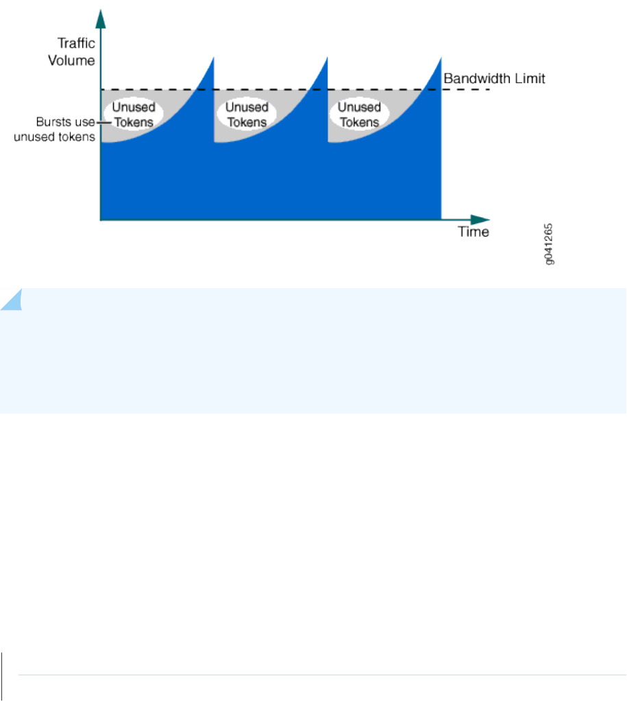
Figure 77: Trac Behavior Using Policer and Burst Size
NOTE: The measured length of a packet changes according to the family type that the policer
applies to. If the policer is applied under the family inet hierarchy, the policer considers only the
IPv4 packet length. If the policer is applied under the family vpls hierarchy, the enre Ethernet
frame (including the Ethernet MAC header) is included in the packet length.
The major factor that aects the policer shaping result is not the conversion adjustment, but the trac
paern since most network trac is not consistent and is not sent at a constant rate. Due to the
uctuaon of the incoming trac rate, some of the allocated tokens are not used. As a result, the
shaped trac rate is lower than you might expect, and the TCP connecon behavior discussed in
"Understanding the Benets of Policers and Token Bucket Algorithms" on page 1910 is a typical example
of this. To alleviate this eect of the lower shaped trac rate, a proper burst size conguraon is
required.
RELATED DOCUMENTATION
Understanding the Benets of Policers and Token Bucket Algorithms | 1910
Determining Proper Burst Size for Trac Policers | 1912
1902

ARP Policer Overview
IN THIS SECTION
Benets of the ARP Policer | 1904
Sending IP packets on a mul access network requires mapping from an IP address to a media access
control (MAC) address (the physical or hardware address).
In an Ethernet environment, Address Resoluon Protocol (ARP) is used to map a MAC address to an IP
address. ARP dynamically binds the IP address (the logical address) to the correct MAC address. Before
sending unicast IP packets, ARP discovers the MAC address used for the Ethernet interface where the IP
address is congured.
Hosts that use ARP maintain a cache of discovered Internet-to-Ethernet address mappings to minimize
the number of ARP broadcast messages. To keep the cache from growing too large, an entry is removed
if it is not used within a certain period of me. Before sending a packet, the host searches its cache for
Internet-to-Ethernet address mapping. If you cannot nd the mapping, the host sends an ARP request.
Starng in Junos OS Release 18.4R1, you can apply policers on ARP trac on SRX Series Firewalls.
Support for ARP policers on pseudowire interfaces on MX Series routers is available in Junos OS Release
20.2R1. The conguraon principles are the same.
You can congure rate liming for the policer by specifying the bandwidth and the burst-size limit.
Packets exceeding the policer limits are discarded. The trac to the Roung Engine is controlled by
applying the policer on ARP trac. Using policers helps prevent network congeson caused by
broadcast storms. You can use policers to specify rate limits on trac. A rewall lter congured with a
policer permits only trac within a specied set of rate limits, thereby providing protecon from denial-
of-service (DoS) aacks. Trac that exceeds the rate limits specied by the policer is either discarded
immediately or is marked as lower priority than trac that is within the rate limits. The switch discards
the lower-priority trac when there is trac congeson.
A policer applies two types of rate limits on trac:
• Bandwidth—The number of bits per second permied, on average
• Maximum burst size—The maximum size permied for bursts of data that exceed the given
bandwidth limit
Policing uses an algorithm to enforce a limit on average bandwidth while allowing bursts up to a
specied maximum value. You can dene specic classes of trac on an interface and apply a set of rate
1903

limits to each class. Aer you name and congure a policer, it is stored as a template. You can then use
the policer in a rewall lter conguraon.
NOTE: On SRX5400, SRX5600, and SRX5800 devices, ARP policer acons are applied on the
SPUs as well as on the Roung Engine. For example, SPU A handles 15000 packets of ARP
trac, and SPU B handles 5000 packets. A policer is congured as rate-limit 10K, discard and
applied to the ARP protocol. As a result, SPU A discards 5000 packets of ARP trac and
forwards 10000 packets to the Roung Engine, and SPU B forwards 5000 packets of ARP the
Roung Engine. The Roung Engine therefore receives a total of 15000 packets of ARP trac.
Benets of the ARP Policer
• Prevents network congeson caused by broadcast storms
• Protects Roung Engines on SRX Series Firewalls that are impacted by broadcast storms
• Provides protecon from denial-of-service (DoS) aacks
Change History Table
Feature support is determined by the plaorm and release you are using. Use Feature Explorer to
determine if a feature is supported on your plaorm.
Release
Descripon
20.2R1 Support for ARP policers on pseudowire interfaces on MX Series routers is available in Junos OS Release
20.2R1.
18.4R1 Starng in Junos OS Release 18.4R1, you can apply policers on ARP trac on SRX Series Firewalls.
RELATED DOCUMENTATION
bandwidth-limit (Hierarchical Policer)
burst-size-limit (Hierarchical Policer)
Example: Conguring ARP Policer | 1905
1904

Example: Conguring ARP Policer
IN THIS SECTION
Requirements | 1905
Overview | 1905
Conguraon | 1906
Vericaon | 1908
This example shows how to congure an Address Resoluon Protocol (ARP) policer on SRX Series
Firewalls.
Support for ARP policers on pseudowire interfaces on MX Series routers is available in Junos OS Release
20.2R1. The conguraon principles are the same as shown here.
Requirements
This example uses the following hardware and soware components:
• SRX Series Firewall.
• Junos OS Release 18.4R1 or later.
Before you begin, see "ARP Policer Overview" on page 1903.
Overview
ARP is used to map a MAC address to an IP address. ARP dynamically binds the IP address (the logical
address) to the correct MAC address. Before IP unicast packets can be sent, ARP discovers the MAC
address used by the Ethernet interface where the IP address is congured. This feature is supported on
all SRX Series Firewalls. The trac to the Roung Engine on the SRX Series Firewall is controlled by
applying the policer on ARP. This prevents network congeson caused by broadcast storms.
NOTE: A default ARP policer named
__default_arp_policer__
is used and shared by all Ethernet
interfaces with family inet congured, by default.
On MX Series routers, you can create policers for ARP trac on pseudowire interfaces. (You congure
rate liming for the policer by specifying the bandwidth and the burst-size limit of a rewall policer and
aaching the policy to a pseudowire interface, just like you would any other interface, and apply the
1905

ARP policer to a pseudowire interface at the [edit interfaces interface-name unit unit-number family inet
policer arp policy-name] level of the hierarchy. Trac that exceeds the specied rate limits can be dropped
or marked as low priority and delivered when congeson permits.
Conguraon
IN THIS SECTION
Conguring ARP Policer on Interface | 1906
This example shows how to
congure rate liming for the policer by specifying the bandwidth and the
burst-size limit.
Conguring ARP Policer on Interface
CLI Quick Conguraon
To quickly congure this example, copy the following commands, paste them into a text le, remove any
line breaks, change any details necessary to match your network conguraon, copy and paste the
commands into the CLI at the [edit] hierarchy level, and then enter commit from conguraon mode.
set firewall policer arp_limit if-exceeding bandwidth-limit 1m
set firewall policer arp_limit if-exceeding burst-size-limit 1m
set firewall policer arp_limit then discard
set interfaces ge-0/0/7 unit 0 family inet policer arp arp_limit
Step-by-Step Procedure
The following example requires you to navigate various levels in the conguraon hierarchy. For
instrucons on how to do that, see "Use the CLI Editor in Conguraon Mode" on page 1892 in the CLI
User Guide.
To congure the ARP policer:
1906

1. Specify the name of the policer.
[edit firewall]
user@host# set policer arp-limit
2. Congure rate liming for the policer.
• Specify the bandwidth limit in bits per second (bps) to control the trac rate on an interface:
[edit firewall policer arp_limit]
user@host# set if-exceeding bandwidth-limit 1m
The range for the bandwidth limit is 1 through 150,000 bps.
• Specify the burst-size limit (the maximum allowed burst size in bytes) to control the amount of
trac bursng:
[edit firewall policer arp_limit]
user@host# set if-exceeding burst-size-limit 1m
To determine the value for the burst-size limit, mulply the bandwidth of the interface on which
the lter is applied by the amount of me to allow a burst of trac at that bandwidth to occur:
burst size = (bandwidth) * (allowable me for burst trac)
The range for the burst-size limit is 1 through 150,00 bytes.
3. Specify the policer acon discard to discard packets that exceed the rate limits.
[edit firewall]
user@host# set policer arp_limit then discard
Discard is the only supported policer acon.
4. Congure the interfaces.
user@host# set interfaces ge-0/0/7 unit 0 family inet policer arp arp_limit
1907

Results
From conguraon mode, conrm your conguraon by entering the show firewall command. If the
output does not display the intended conguraon, repeat the instrucons in this example to correct.
[edit]
user@host# show firewall
policer arp_limit {
if-exceeding {
bandwidth-limit 1m;
burst-size-limit 1m;
}
then discard;
}
[edit]
user@host# show interfaces
ge-0/0/7 {
unit 0 {
family inet {
policer {
arp arp_limit;
}
}
}
}
Aer you are done conguring the device, enter commit from conguraon mode.
Vericaon
IN THIS SECTION
Verifying the results of arp policer | 1909
To conrm that the conguraon is working properly, perform these tasks:
1908
Verifying the results of arp policer
Purpose
Verify the results of the Arp policer.
Acon
From the top of the conguraon in operaonal mode, enter the show policer
policer-name
command.
user@host> show policer
arp_limit-ge-0/0/7.0-inet-arp
Policers:
Name Bytes Packets
arp_limit-ge-0/0/7.0-inet-arp 0 0
Meaning
The show policer
policer-name
command displays the names of all rewall lters and policers that are
congured on the device.
Change History Table
Feature support is determined by the plaorm and release you are using. Use Feature Explorer to
determine if a feature is supported on your plaorm.
Release
Descripon
20.2R1 Support for MX Series routers is available in Junos OS Release 20.2R1, and the conguraon principles
are the same as shown here.
RELATED DOCUMENTATION
ARP Policer Overview | 1903
1909

Understanding the Benets of Policers and Token Bucket Algorithms
IN THIS SECTION
Scenario 1: Single TCP Connecon | 1910
Scenario 2: Mulple TCP Connecons | 1911
This topic describes some scenarios that demonstrate how dicult it is to control trac that comes into
your network without the help of policers and the token bucket algorithm. These scenarios assume that
trac is coming from a TCP-based connecon. Depending on the number of TCP connecons, policers
can have dierent aects on rate limits.
This topic presents the following scenarios:
• "Scenario 1: Single TCP Connecon" on page 1910
• "Scenario 2: Mulple TCP Connecons" on page 1911
Scenario 1: Single TCP Connecon
Figure 78 on page 1911 shows the trac loading on an interface with a policer congured. When the
trac rate reaches the congured bandwidth limit (which results in a packet drop), a TCP slow-start
mechanism reduces the trac rate down to half of what it was. When the trac rate rises again, the
same cycle repeats.
1910

Figure 78: Policer Behavior with a Single TCP Connecon
The problem presented in this scenario is that some bandwidth is available, but it is not being used by
the trac. The unused bandwidth shown in Figure 78 on page 1911 is the result of an overall data
throughput that is lower than the congured bandwidth value. This example is an extreme case because
there is only a single TCP connecon.
Scenario 2: Mulple TCP Connecons
With mulple TCP connecons or some background non-TCP-based trac, there is less unused
bandwidth, as depicted in Figure 79 on page 1912. However, the same issue of unused bandwidth sll
exists if all the TCP connecons experience a drop when the aggregated trac rate exceeds the
congured bandwidth limit.
1911

Figure 79: Policer Behavior with Background Trac (Mulple TCP Connecons)
To reduce the problem of unused bandwidth in your network, you can congure a burst size.
RELATED DOCUMENTATION
Policer Implementaon Overview | 1899
Determining Proper Burst Size for Trac Policers | 1912
Determining Proper Burst Size for Trac Policers
IN THIS SECTION
Policer Burst Size Limit Overview | 1913
Eect of Burst-Size Limit | 1913
Two Methods for Calculang Burst-Size Limit | 1915
Comparison of the Two Methods | 1916
1912

Policer Burst Size Limit Overview
A policer burst-size limit controls the number of bytes of trac that can pass unrestricted through a
policed interface when a burst of trac pushes the average transmit or receive rate above the
congured bandwidth limit. The actual number of bytes of bursty trac allowed to pass through a
policed interface can vary from zero to the congured burst-size limit, depending on the overall trac
load.
By conguring a proper burst size, the eect of a lower shaped rate is alleviated. Use the burst-size-limit
statement to congure the burst size.
NOTE: If you set the burst-size limit too low, too many packets will be subjected to rate liming.
If you set the burst-size limit too high, too few packets will be rate-limited.
Consider these two main factors when determining the burst size to use:
• The allowed duraon of a blast of trac on the line.
• The burst size is large enough to handle the maximum transmission unit (MTU) size of the packets.
The following general guidelines apply to choosing a policer burst-size limit:
• A burst-size limit should not be set lower than 10 mes the MTU of the trac on the interface to be
policed.
• The amount of me to allow a burst of trac at the full line rate of a policed interface should not be
lower than 5 ms.
• The minimum and maximum values you can specify for a policer burst-size limit depends on the
policer type (two-color or three-color).
BEST PRACTICE: The preferred method for choosing a burst-size limit is based on the line
rate of the interface on which you apply the policer and the amount of me you want to
allow a burst of trac at the full line rate.
Eect of Burst-Size Limit
Bursty trac requires a relavely large burst size so that extra tokens can be allocated into the token
bucket for upcoming trac to use.
1913

Bursty Trac Policed Without a Burst-Size Limit
Figure 80 on page 1914 shows an extreme case of bursty trac where the opportunity to allocate
tokens is missed, and the bandwidth goes unused because a large burst size is not congured.
Figure 80: Bursty Trac Without Congured Burst Size (Excessive Unused Bandwidth)
Burst-Size Limit Congured to Match Bandwidth Limit and Flow Bursness
Figure 81 on page 1915 depicts how bandwidth usage changes when a large burst size is congured to
handle bursty trac. The large burst size minimizes the amount of unused bandwidth because tokens
are being allocated in between the bursts of trac that can be used during trac peaks. The burst size
determines the depth of the token bucket.
1914

Figure 81: Bursty Trac with Congured Burst Size (Less Unused Bandwidth)
Burst-Size Limit That Depletes All Accumulated Tokens
Conguring a large burst size for the unused tokens creates another issue. If the burst size is set to a
very large value, the burst of trac can be transmied from the interface at line rate unl all the
accumulated tokens in the token bucket are used up. This means that conguring a large burst size can
allow too many packets to avoid rate liming, which can lead to a trac rate that exceeds the
bandwidth limit for an extended period of me.
If the average rate is considered within 1 second, the rate is sll below the congured bandwidth limit.
However, the downstream device might not be able to handle bursty trac, so some packets might be
dropped.
Two Methods for Calculang Burst-Size Limit
For policers congured on MX Series, M120, and M320 routers, and EX Series switches, congurable
burst-size limit values range from 1 ms through 600 ms of trac at the policer rate (the congured
bandwidth limit).
Because one burst size is not suitable for every trac paern, select the best burst size for an interface
by performing experimental conguraons. For your rst test conguraon, select the burst-size limit by
using one of the calculaon methods described in the next two secons.
Calculaon Based on Interface Bandwidth and Allowable Burst Time
If the bandwidth of the policed interface is known, the preferred method for calculang the policer
burst-size limit is based on the following values:
1915

• bandwidth—Line rate of the policed interface (in bps units)
• burst-period—Allowable trac-burst me (5 ms or longer)
To calculate policer bandwidth in bytes:
bandwidth X burst-period / 8
Calculaon Based on Interface Trac MTU
If the bandwidth of the policed interface is unknown, calculate the policer burst-size limit based on the
following value:
• interface MTU—Maximum transmission unit (in bytes) for the policed interface.
To calculate policer bandwidth in bytes:
interface MTU Χ 10
Comparison of the Two Methods
Figure 82 on page 1917 illustrates the relaonship between the policer rate (the congured bandwidth
limit) and the eecve burst-size limit for the two methods of calculang the best policer burst-size
limit. For the method based on interface bandwidth and allowable burst me, the correlaon is labeled
5 ms. For the method based on MTU size, the correlaon is labeled 10 MTU.
1916

Figure 82: Comparing Burst Size Calculaon Methods
For a policer burst-size limit calculated using the 5 ms method, the eecve burst-size limit is
proporonal to the congured bandwidth limit. With a very low bandwidth limit, the eecve burst-size
limit might be so small that the policer rate-limits trac more aggressively than desired. For example, a
trac “burst” consisng of two MTU-sized packets might be rate-limited. In this scenario, a policer
burst-size limit calculated using the 10 MTU method appears to be a beer choice.
10 x MTU Method for Selecng Inial Burst Size for Gigabit Ethernet with 100 Kbps
Bandwidth
The following sequence illustrates the use of the 10 x MTU method for selecng an inial burst size for
test conguraons for a Gigabit Ethernet interface congured with a 100 Kbps bandwidth limit:
1. If you congure a 100 ms burst-size limit, the maximum amount of trac allowed to pass through the
interface unrestricted is 1250 bytes, calculated as follows:
100,000 bps x 0.1 s
100 Kbps x 100 ms = ————————————————————— = 1250 bytes
8 bits per byte
2. In theory, a 10 x MTU burst size would allow up to 15,000 bytes to pass unrestricted. However, the
maximum congurable burst-size limit for MX Series, M120, and M320 routers is 600 ms of the
bandwidth limit. If you congure the maximum burst-size limit of 600 ms of the bandwidth limit, the
1917

maximum amount of trac allowed to pass through the interface unrestricted is 7500 bytes,
calculated as follows:
100,000 bps x 0.6 s
100 Kbps x 600 ms = ————————————————————— = 7500 bytes
8 bits per byte
On a Gigabit Ethernet interface, a congured burst-size limit of 600 ms creates a burst duraon of
60 μs at Gigabit Ethernet line rate, calculated as follows:
7500 bytes 60,000 bits
———————————— = ——————————————————— = 0.00006 s = 60 μs
1 Gbps 1,000,000,000 bps
3. If the downstream device is unable to handle the amount of bursty trac allowed using the inial
burst size conguraon, reduce the burst-size limit unl you achieve acceptable results.
5 ms Method for Selecng Inial Burst Size for Gigabit Ethernet Interface with 200 Mbps
Bandwidth
The following sequence illustrates the use of the 5 ms method for selecng an inial burst size for test
conguraons for a Gigabit Ethernet interface congured with a 200 Mbps bandwidth limit. This
example calculaon shows how a larger burst-size limit can aect the measured bandwidth rate.
1. If you congure a 5 ms burst-size limit, the maximum amount of trac allowed to pass through the
interface unrestricted is 125,000 bytes (approximately 83 1500-byte packets), calculated as follows:
200,000,000 bps x 0.005 s
200 Mbps x 5 ms = —————————————————————————— = 125,000 bytes
8 bits per byte
1918

On a Gigabit Ethernet interface, a congured burst-size limit of 5 ms creates a burst duraon of 1 ms
at Gigabit Ethernet line rate, calculated as follows:
125,000 bytes 1,000,000 bits
——————————————— = ——————————————————— = 0.001 s = 1 ms
1 Gbps 1,000,000,000 bps
The average bandwidth rate in 1 second becomes 200 Mbps + 1 Mbps = 201 Mbps, which is a
minimal increase over the congured bandwidth limit at 200 Mbps.
2. If you congure a 600 ms burst-size limit, the maximum amount of trac allowed to pass through the
interface unrestricted is 15 Mbytes (approximately 10,000 1500-byte packets), calculated as follows:
200,000,000 bps x 0.6 s
200 Mbps x 600 ms = ————————————————————————— = 15,000,000 bytes
8 bits per byte
On a Gigabit Ethernet interface, a congured burst-size limit of 600 ms creates a burst duraon of
120 ms at Gigabit Ethernet line rate, calculated as follows:
15,000,000 bytes 120,000,000 bits
—————————————— = ——————————————————— = 0.12 s = 120 ms
1 Gbps 1,000,000,000 bps
The average bandwidth rate in 1 second becomes 200 Mbps + 120 Mbps = 320 Mbps, which is much
higher than the congured bandwidth limit at 200 Mbps.
200 Mbps Bandwidth Limit, 5 ms Burst Duraon
If a 200 Mbps bandwidth limit is congured with a 5 ms burst size, the calculaon becomes 200 Mbps x
5 ms = 125 Kbytes, which is approximately 83 1500-byte packets. If the 200 Mbps bandwidth limit is
1919

congured on a Gigabit Ethernet interface, the burst duraon is 125000 bytes / 1 Gbps = 1 ms at the
Gigabit Ethernet line rate.
200 Mbps Bandwidth Limit, 600 ms Burst Duraon
If a large burst size is congured at 600 ms with the bandwidth limit congured at 200 Mbps, the
calculaon becomes 200 Mbps x 600 ms = 15 Mbytes. This creates a burst duraon of 120 ms at the
Gigabit Ethernet line rate. The average bandwidth rate in 1 second becomes 200 Mbps + 15 Mbytes =
320 Mbps, which is much higher than the congured bandwidth limit at 200 Mbps. This example shows
that a larger burst size can aect the measured bandwidth rate.
RELATED DOCUMENTATION
Policer Implementaon Overview | 1899
Understanding the Benets of Policers and Token Bucket Algorithms | 1910
Controlling Network Access Using Trac Policing Overview
IN THIS SECTION
Congeson Management for IP Trac Flows | 1920
Trac Limits | 1921
Trac Color Marking | 1922
Forwarding Classes and PLP Levels | 1924
Policer Applicaon to Trac | 1925
Congeson Management for IP Trac Flows
Trac policing, also known as
rate liming
, is an essenal component of network access security that is
designed to thwart denial-of-service (DoS) aacks. Trac policing enables you to control the maximum
rate of IP trac sent or received on an interface and also to paron network trac into mulple
priority levels, also known as
classes of service
. A policer denes a set of trac rate limits and sets
consequences for trac that does not conform to the congured limits. Packets in a trac ow that
do not conform to trac limits are either discarded or marked with a dierent forwarding class or packet
loss priority (PLP) level.
1920

With the excepon of policers congured to rate-limit aggregate trac (all protocol families and logical
interfaces congured on a physical interface), you can apply a policer to all IP packets in a Layer 2 or
Layer 3 trac ow at a
logical interface
.
With the excepon of policers congured to rate-limit based on physical interface media rate, you can
apply a policer to specic IP packets in a Layer 3 trac ow at a logical interface by using a stateless
rewall lter
.
You can apply a policer to inbound or outbound interface trac. Policers applied to inbound trac help
to conserve resources by dropping trac that does not need to be routed through a network. Dropping
inbound trac also helps to thwart denial-of-service (DoS) aacks. Policers applied to outbound trac
control the bandwidth used.
NOTE: Trac policers are instanated on a per-PIC basis. Trac policing does not work when
the trac for one local policy decision funcon (L-PDF) subscriber is distributed over mulple
Mulservices PICs in an AMS group.
Trac Limits
Junos OS policers use a
token bucket algorithm
to enforce a limit on an average transmit or receive rate
of trac at an interface while allowing bursts of trac up to a maximum value based on the congured
bandwidth limit and congured burst size. The token bucket algorithm oers more exibility than a
leaky
bucket algorithm
in that you can allow a specied trac burst before starng to discard packets or apply
a penalty such as packet output-queuing priority or packet-drop priority.
In the token-bucket model, the bucket represents the rate-liming funcon of the policer. Tokens are
added to the bucket at a xed rate, but once the specied depth of the bucket is reached, tokens
allocated aer cannot be stored and used. Each token represents a “credit” for some number of bits, and
tokens in the bucket are “cashed in” for the ability to transmit or receive trac at the interface. When
sucient tokens are present in the bucket, a trac ow connues unrestricted. Otherwise, packets
might be dropped or else re-marked with a lower forwarding class, a higher packet loss priority (PLP)
level, or both.
• The rate at which tokens are added to the bucket represents the highest average transmit or receive
rate in bits per second allowed for a given service level. You specify this highest average trac rate
as the
bandwidth limit
of the policer. If the trac arrival rate (or xed bits-per-second) is so high that
at some point insucient tokens are present in the bucket, then the trac ow is no longer
conforming to the trac limit. During periods of relavely low trac (trac that arrives at or departs
from the interface at average rates below the token arrival rate), unused tokens accumulate in the
bucket.
• The depth of the bucket in bytes controls the amount of back-to-back bursng allowed. You specify
this factor as the
burst-size limit
of the policer. This second limit aects the average transmit or
1921

receive rate by liming the number of bytes permied in a transmission burst for a given interval of
me. Bursts exceeding the current burst-size limit are dropped unl there are sucient tokens
available to permit the burst to proceed.
Figure 83: Network Trac and Burst Rates
As shown in the gure above, a UPC bar code is a good facsimile of what trac looks like on the line;
an interface is either transming (bursng at full rate) or it is not. The black lines represent periods
of data transmission and the white space represents periods of silence when the token bucket can
replenish.
Depending on the type of policer used, packets in a policed trac ow that surpasses the dened limits
might be implicitly set to a higher PLP level, assigned to a congured forwarding class or set to a
congured PLP level (or both), or simply discarded. If packets encounter downstream congeson,
packets with a low PLP level are less likely to be discarded than those with a medium-low, medium-high, or high
PLP level.
Trac Color Marking
Based on the parcular set of trac limits congured, a policer idenes a trac ow as belonging to
one of either two or three categories that are similar to the colors of a trac light used to control
automobile trac.
•
Single-rate two-color
—A two-color marking policer (or “policer” when used without qualicaon)
meters the trac stream and classies packets into two categories of packet loss priority (PLP)
according to a congured bandwidth and burst-size limit. You can mark packets that exceed the
bandwidth and burst-size limit in some way, or simply discard them.
A policer is most useful for metering trac at the port (physical interface) level.
•
Single-rate three-color
—This type of policer is dened in RFC 2697,
A Single Rate Three Color
Marker
, as part of an assured forwarding (AF) per-hop-behavior (PHB) classicaon system for a
1922

Dierenated Services (DiServ) environment. This type of policer meters trac based on the
congured commied informaon rate (CIR), commied burst size (CBS), and the excess burst size
(EBS). Trac is marked as belonging to one of three categories (green, yellow, or red) based on
whether the packets arriving are below the CBS (green), exceed the CBS (yellow) but not the EBS, or
exceed the EBS (red).
A single-rate three-color policer is most useful when a service is structured according to packet
length and not peak arrival rate.
•
Two-rate three-color
—This type of policer is dened in RFC 2698,
A Two Rate Three Color Marker
, as
part of an assured forwarding (AF) per-hop-behavior (PHB) classicaon system for a Dierenated
Services (DiServ) environment. This type of policer meters trac based on the congured CIR and
peak informaon rate (PIR), along with their associated burst sizes, the CBS and
peak burst size
(PBS). Trac is marked as belonging to one of three categories (green, yellow, or red) based on
whether the packets arriving are below the CIR (green), exceed the CIR (yellow) but not the PIR, or
exceed the PIR (red).
A two-rate three-color policer is most useful when a service is structured according to arrival rates
and not necessarily packet length.
Policer acons are implicit or explicit and vary by policer type. The term
Implicit
means that Junos
assigns the loss-priority automacally. Table 109 on page 1923 describes the policer acons.
Table 109: Policer
Acons
Policer Marking Implicit Acon Congurable Acon
Single-rate two-color Green (Conforming) Assign low loss priority None
Red (Nonconforming) None Assign low or high loss
priority, assign a
forwarding class, or
discard
On some plaorms, you
can assign medium-low or
medium-high loss priority
Single-rate three-color Green (Conforming) Assign low loss priority None
Yellow (Above the CIR
and CBS)
Assign medium-high loss
priority
None
1923

Table 109: Policer Acons
(Connued)
Policer Marking Implicit Acon Congurable Acon
Red (Above the EBS) Assign high loss priority Discard
Two-rate three-color Green (Conforming) Assign low loss priority None
Yellow (Above the CIR
and CBS)
Assign medium-high loss
priority
None
Red (Above the PIR and
PBS)
Assign high loss priority Discard
Forwarding Classes and PLP Levels
A packet’s forwarding class assignment and PLP level are used by the Junos OS class of service (CoS)
features. The Junos OS CoS features include a set of mechanisms that you can use to provide
dierenated services when best-eort trac delivery is insucient. For router (and switch) interfaces
that carry IPv4, IPv6, and MPLS trac, you can congure CoS features to take in a single ow of trac
entering at the edge of your network and provide dierent levels of service across the network—internal
forwarding and scheduling (queuing) for output—based on the forwarding class assignments and PLP
levels of the individual packets.
NOTE: Forwarding-class or loss-priority assignments performed by a policer or a stateless
rewall lter override any such assignments performed on the ingress by the CoS default IP
precedence classicaon at all logical interfaces or by any congured behavior aggregate (BA)
classier that is explicitly mapped to a logical interface.
Based on CoS conguraons, packets of a given forwarding class are transmied through a specic
output queue, and each output queue is associated with a transmission service level dened in a
scheduler
.
Based on other CoS conguraons, when packets in an output queue encounter congeson, packets
with higher loss-priority values are more likely to be dropped by the random early detecon (RED)
algorithm. Packet loss priority values aect the scheduling of a packet without aecng the packet’s
relave ordering within the trac ow.
1924

Policer Applicaon to Trac
Aer you have dened and named a policer, it is stored as a template. You can later use the same policer
name to provide the same policer conguraon each me you want to use it. This eliminates the need to
dene the same policer values more than once.
You can apply a policer to a trac ow in either of two ways:
• You can congure a standard stateless rewall lter that species the policer
policer-name
nonterminang acon or the three-color-policer (single-rate | two-rate)
policer-name
nonterminang
acon. When you apply the standard lter to the input or output at a logical interface, the policer is
applied to all packets of the lter-specic protocol family that match the condions specied in the
lter conguraon.
With this method of applying a policer, you can dene specic classes of trac on an interface and
apply trac rate-liming to each class.
• You can apply a policer directly to an interface so that trac rate-liming applies to all trac on that
interface, regardless of protocol family or any match condions.
You can congure policers at the queue, logical interface, or Layer 2 (MAC) level. Only a single policer is
applied to a packet at the egress queue, and the search for policers occurs in this order:
• Queue level
• Logical interface level
• Layer 2 (MAC) level
RELATED DOCUMENTATION
Stateless Firewall Filter Overview | 778
Trac Policer Types | 1926
Order of Policer and Firewall Filter Operaons | 1930
Packet Flow Through the Junos OS CoS Process Overview
1925

Trac Policer Types
IN THIS SECTION
Single-Rate Two-Color Policers | 1926
Three-Color Policers | 1927
Hierarchical Policers | 1928
Two-Color and Three-Color Policer Opons | 1928
Single-Rate Two-Color Policers
You can use a single-rate two-color policer, or “policer” when used without qualicaon, to rate-limit a
trac ow to an average bits-per-second arrival rate (specied by the single specied bandwidth limit)
while allowing bursts of trac for short periods (controlled by the single specied burst-size limit). This
type of policer categorizes a trac ow as either green (conforming) or red (nonconforming). Packets in
a green ow are implicitly set to a low loss priority and then transmied. Packets in a red ow are
handled according to acons specied in the policer conguraon. Packets in a red ow can be marked
—set to a specied forwarding class, set to a specied loss priority, or both—or they can be discarded.
A single-rate two-color policer is most useful for metering trac at the port (physical interface) level.
Basic Single-Rate Two-Color Policer
You can apply a basic single-rate two-color policer to Layer 3 trac in either of two ways: as an
interface policer or as a
rewall lter
policer. You can apply the policer as an <!--<new-
term>interface policer</new-term>-->, meaning that you apply the policer directly to a
logical interface
at the protocol family level. If you want to apply the policer to selected packets only, you can apply the
policer as a
rewall lter policer
, meaning that you reference the policer in a stateless rewall lter term
and then apply the lter to a logical interface at the protocol family level.
Bandwidth Policer
A bandwidth policer is simply a single-rate two-color policer that is dened using a bandwidth limit
specied as a percentage value rather than as an absolute number of bits per second. When you apply
the policer (as an interface policer or as a rewall lter policer) to a logical interface at the protocol
family level, the eecve bandwidth limit is calculated based on either the physical interface media rate
or the logical interface congured shaping rate.
1926
Logical Bandwidth Policer
A logical bandwidth policer is a bandwidth policer for which the eecve bandwidth limit is calculated
based on the logical interface congured shaping rate. You can apply the policer as a rewall lter
policer only, and the rewall lter must be congured as an interface-specic lter. When you apply an
interface-specic lter to mulple logical interfaces on supported roung plaorms, any count or policer
acons act on the trac stream entering or exing each individual interface, regardless of the sum of
trac on the mulple interfaces.
Three-Color Policers
The Junos OS supports two types of three-color policers: single-rate and two-rate. The main dierence
between a single-rate and a two-rate policer is that the single-rate policer allows bursts of trac for
short periods, while the two-rate policer allows more sustained bursts of trac. Single-rate policing is
implemented using a single token-bucket model, so that periods of relavely low trac must occur
between trac bursts to allow the token bucket to rell. Two-rate policing is implemented using a dual
token-bucket model, which allows bursts of trac for longer periods.
Single-Rate Three-Color Policers
The single-rate three-color type of policer is dened in RFC 2697,
A Single Rate Three Color Marker
.
You use this type of policer to rate-limit a trac ow to a single rate and three trac categories (green,
yellow, and red). A single-rate three-color policer denes a
commied
bandwidth limit and burst-size
limit plus an
excess
burst-size limit. Trac that conforms to the commied trac limits is categorized as
green (conforming). Trac that conforms to the bandwidth limit while allowing bursts of trac as
controlled by the excess burst-size limit is categorized as yellow. All other trac is categorized as red.
A single-rate three-color policer is most useful when a service is structured according to packet length,
not peak arrival rate.
Two-Rate Three-Color Policers
The two-rate three-color type of policer is dened in RFC 2698,
A Two Rate Three Color Marker
. You
use this type of policer to rate-limit a trac ow to two rates and three trac categories (green, yellow,
and red). A two-rate three-color policer denes a
commied
bandwidth limit and burst-size limit plus a
peak
bandwidth limit and burst-size limit. Trac that conforms to the commied trac limits is
categorized as green (conforming). Trac that exceeds the commied trac limits but remains below
the peak trac limits is categorized as yellow. Trac that exceeds the peak trac limits is categorized as
red.
A two-rate three-color policer is most useful when a service is structured according to arrival rates and
not necessarily packet length.
1927
Hierarchical Policers
You can use a hierarchical policer to rate-limit ingress Layer 2 trac at a physical or logical interface and
apply dierent policing acons based on whether the packets are classied for expedited forwarding
(EF) or for a lower priority output queue. This feature is supported on SONET interfaces hosted on
M40e, M120, and M320 edge routers with incoming Flexible PIC Concentrators (FPCs) as SFPC and
outgoing FPCs as FFPC, and on T320, T640, and T1600 core routers with Enhanced Intelligent Queuing
(IQE) PICs.
Two-Color and Three-Color Policer Opons
Both two-color and three-color policers can be congured with the following opons:
Logical Interface (Aggregate) Policers
A logical interface policer—also called an aggregate policer—is a two-color or three-color policer that you
can apply to mulple protocol families on the same logical interface without creang mulple instances
of the policer. You apply a logical interface policer directly to a logical interface conguraon (and not by
referencing the policer in a stateless rewall lter and then applying the lter to the logical interface).
• You can apply the policer at the interface logical unit level to rate-limit all trac types, regardless of
the protocol family.
When applied in this manner, the logical interface policer will be used by all trac types (inet, intet6,
etc.) and across all layers (layer 2, layer 3) no maer where the policer is aached on the logical
interface.
• You can also apply the policer at the logical interface protocol family level, to rate-limit trac for a
specic protocol family.
You can apply a logical interface policer to unicast trac only. For informaon about conguring a
stateless rewall lter for ooded trac, see “
Applying Forwarding Table Filters
” in the “Trac Sampling,
Forwarding, and Monitoring” secon of the Roung Policies, Firewall Filters, and Trac Policers User
Guide.
Physical Interface Policers
A physical interface policer is a two-color or three-color policer that applies to all logical interfaces and
protocol families congured on a physical interface, even if the logical interfaces belong to dierent
roung instances. You apply a physical interface policer to a logical interface at the protocol level
through a physical interface lter only, but rate liming is performed aggregately for all logical interfaces
and protocol families congured on the underlying physical interface.
1928

This feature enables you to use a single policer instance to perform aggregate policing for dierent
protocol families and dierent logical interfaces on the same physical interface.
Policers Applied to Layer 2 Trac
In addion to hierarchical policing, you can also apply single-rate two-color policers and three-color
policers (both single-rate and two-rate) to Layer 2 input or output trac. You must congure the two-
color or three-color policer as a logical interface policer and reference the policer in the interface
conguraon at the logical unit level, and not at the protocol level. You cannot apply a two-color or
three-color policer to Layer 2 trac as a stateless rewall lter acon.
Muleld Classicaon
Like behavior aggregate (BA) classicaon, which is somemes referred to as class-of-service (CoS) value
trac classicaon, muleld classicaon is a method of classifying incoming trac by associang
each packet with a forwarding class, a packet loss priority level, or both. The CoS scheduling
conguraon assigns packets to output queues based on forwarding class. The CoS random early
detecon (RED) process uses the drop probability conguraon, output queue fullness percentage, and
packet loss priority to drop packets as needed to control congeson at the output stage.
BA classicaon and muleld classicaon use dierent elds of a packet to perform trac
classicaon. BA classicaon is based on a
CoS value
in the IP packet header. Muleld classicaon
can be based on
mulple elds
in the IP packet header, including CoS values. Muleld classicaon is
used instead of BA classicaon when you need to classify packets based on informaon in the packet
other than the CoS values only. Muleld classicaon is congured using a stateless rewall lter term
that matches on any packet header elds and associates matched packets with a forwarding class, a loss
priority, or both. The forwarding class or loss priority can be set by a rewall lter acon or by a policer
referenced as a rewall lter acon.
RELATED DOCUMENTATION
Controlling Network Access Using Trac Policing Overview | 1920
Order of Policer and Firewall Filter Operaons | 1930
Two-Color Policer Conguraon Overview | 2038
Three-Color Policer Conguraon Overview | 2122
Hierarchical Policer Conguraon Overview | 1932
Two-Color Policing at Layer 2 Overview
Three-Color Policing at Layer 2 Overview
1929

Order of Policer and Firewall Filter Operaons
You can apply a both a trac policer and a stateless
rewall lter
(with or without policing acons) to a
single
logical interface
at the same me. In this case, the order of precedence of operaons is such that
policers applied directly to the logical interface are evaluated before input lters but aer output lters.
• If an input rewall lter is congured on the same logical interface as a policer, the policer is
executed rst.
• If an output rewall lter is congured on the same logical interface as a policer, the rewall lter is
executed rst.
Figure 84 on page 1930 illustrates the order of policer and rewall lter processing at the same
interface.
Figure 84: Incoming and Outgoing Policers and Firewall Filters
NOTE: Order of policer and rewall operaons applies only to policers that have been applied
directly to the logical interface and not to policers referenced within a rewall lter.
RELATED DOCUMENTATION
How Standard Firewall Filters Evaluate Packets | 795
Comparison of Roung Policies and Firewall Filters | 9
Two-Color Policer Conguraon Overview | 2038
Three-Color Policer Conguraon Overview | 2122
Hierarchical Policer Conguraon Overview | 1932
Understanding the Frame Length for Policing Packets
Table 110 on page 1931 describes the packet lengths that are considered when you use a trac policer.
1930

Table 110: Packet Lengths Considered for Trac Policers
Protocol Policing Packet Lengths
Any L3 frame including header
IPv4 L3 frame including header
IPv6 L3 frame including header
MPLS L3 frame including header
VPLS MAC
Bridge MAC
CCC MAC
RELATED DOCUMENTATION
Policer Overhead to Account for Rate Shaping in the Trac Manager | 2110
Supported Standards for Policing
Three-color policers are part of an assured forwarding (AF) per-hop-behavior (PHB) classicaon system
for a Dierenated Services (DiServ) environment, which is described and dened in the following
RFCs:
• RFC 2474,
Denion of the Dierenated Services Field (DS Field) in the IPv4 and IPv6 Headers
• RFC 2475,
An Architecture for Dierenated Service
• RFC 2597,
Assured Forwarding PHB Group
• RFC 2598,
An Expedited Forwarding PHB
• RFC 2698,
A Two Rate Three Color Marker
1931

In a DiServ environment, the most signicant 6 bits of the type-of-service (ToS) octet in the IP header
contain a value called the
Dierenated Services code point
(DSCP). Within the DSCP eld, the most
signicant 3 bits are interpreted as the
IP precedence
eld, which can be used to select dierent per-
hop forwarding treatments for the packet.
Hierarchical Policer Conguraon Overview
Hierarchically rate-limits Layer 2 ingress trac for all protocol families. Cannot be applied to egress
trac, Layer 3 trac, or at a specic protocol level of the interface hierarchy.
Supported on the following interfaces:
• SONET interfaces hosted on M40e, M120, and M320 edge routers with incoming FPCs as SFPC and
outgoing FPCs as FFPC.
• SONET interfaces hosted on T320, T640, and T1600 core routers with Enhanced Intelligent Queuing
(IQE) PICs.
• Ethernet interfaces on Gigabit Ethernet Intelligent Queuing 2 (IQ2) and Ethernet Enhanced IQ2
(IQ2E) PICs.
• MX Series routers with MPC or DPC.
Table 111 on page 1932 describes the hierarchy levels at which you can congure and apply hierarchical
policers.
Table 111: Hierarchical Policer
Conguraon and Applicaon Summary
Policer Conguraon Layer 2 Applicaon Key Points
Hierarchical Policer
1932

Table 111: Hierarchical Policer Conguraon and Applicaon Summary
(Connued)
Policer Conguraon Layer 2 Applicaon Key Points
Aggregate and premium policing
components of a hierarchical
policer:
[edit firewall]
hierarchical-policer
policer-name
{
aggregate {
if-exceeding {
bandwidth-limit
bps
;
burst-size-limit
bytes
;
}
then {
discard;
forwarding-class
class-name
;
loss-priority
supported-value
;
}
}
premium {
if-exceeding {
bandwidth-limit
bps
;
burst-size-limit
bytes
;
}
then {
discard;
}
}
}
Opon A—Apply directly to Layer 2 input
trac on a physical interface:
[edit interfaces]
interface-name
{
layer2-policer {
input-hierarchical-policer
policer-
name
;
}
}
Hierarchically rate-limit
Layer 2 ingress trac for all
protocol families and logical
interfaces congured on a
physical interface.
Include the layer2-policer
conguraon statement at
the [edit interfaces
interface-name
] hierarchy
level.
NOTE: If you apply a
hierarchical policer at a
physical interface, you
cannot also apply a
hierarchical policer to any of
the member logical
interfaces.
Opon B—Apply directly to Layer 2 input
trac on a logical interface.
[edit interfaces]
interface-name
{
unit
unit-number
{
layer2-policer {
input-hierarchical-policer
policer-name
;
}
}
}
Hierarchically rate-limit
Layer 2 ingress trac for all
protocol families congured
on a specic logical
interface.
Include the layer2-policer
conguraon statement at
the [edit interfaces
interface-name
unit
unit-
number
] hierarchy level.
NOTE: You must congure
at least one protocol family
for the logical interface.
RELATED DOCUMENTATION
Hierarchical Policers | 1980
1933

Understanding Enhanced Hierarchical Policers
IN THIS SECTION
Guidelines for conguring enhanced hierarchical policer | 1935
Example: Conguring an enhanced hierarchical policer | 1935
Use the enhanced hierarchical policer conguraon to rate limit trac based on packets classied on
the trac priority. Congure trac policing at four levels of hierarchies with respect to the trac
priority.
NOTE: This feature is available only on ACX7100-32C, ACX7100-48L, ACX7509, and ACX7024
devices.
In an enhanced hierarchical policer conguraon, up to four policers are dened. Each policer maps to a
trac priority. The four trac priories, arranged as per their order of precedence are High, Medium-
High, Medium-Low, and Low. The trac priories are hierarchical – High is the trac priority with the
highest precedence and Low is the trac priority with the lowest precedence. It implies that a policer
dened for the High trac priority has a higher precedence than the rest of the policers or a policer
dened for the Low trac priority has a lower precedence than the rest of the policers.
All policers (one or up to four) in an enhanced hierarchical policer conguraon, consume bandwidth
from a maximum alloed bandwidth – in Table 1 this maximum alloed bandwidth is 65 mbps. Each
policer is alloed a Conrmed Informaon Rate (CIR) and Maximum Conrmed Informaon Rate from
this maximum alloed bandwidth. As a guideline, the CIR and Max CIR values are always the same for
the policer with the highest precedence.
Residue bandwidth or unused bandwidth is carried over to lower precedence policers. As can be noted
in Table 112 on page 1935, medium-high policer inherits unused bandwidth from high policer. Medium-
low policer inherits from high and medium-high policers. Low policer inherits from the other three higher
precedence policers. It is recommended that MAX CIR of a parcular level is equal to the CIR of current
level + combined CIR of previous/top levels.
1934

Table 112: Example enhanced hierarchical policer conguraon
Policer Conguraons
Policer-level/trac-priority CIR MAX CIR
high 5mbps 5mbps
medium-high 10mbps 15mbps
medium-low 20mbps 35mbps
low 30mbps 65mbps
Guidelines for conguring enhanced hierarchical policer
• An enhanced hierarchical policer is lter-specic. Filter-specic policer semancs is to be used for
hierarchical policer as mulple terms will point to same policer.
• Counter name must be same for all the terms mapped to enhanced-hierarchical-policer acon under
same hierarchy level.
• It is mandatory to congure all the levels of an enhanced hierarchical policer with respecve policer
bandwidth rates and burst size conguraons. If there is no requirement to congure all four levels,
the unwanted levels must specify least supported CIR, MAX CIR and CBS rates. It is recommended
that rewall lter terms not be mapped to these unwanted levels.
• Each enhanced hierarchical policer level must be congured with the acon to discard the packets
exceeding the congured bandwidth.
Example: Conguring an enhanced hierarchical policer
In this example:
• An enhanced hierarchical policer is dened.
• A rewall lter is dened and policer is applied in the rewall lter. The rewall lter is applied to an
interface.
• Policer stascs is displayed.
1935

Requirements:
• Junos OS Release 23.3 R1 or later.
• An ACX7100-32C, ACX7100-48L, ACX7509, or ACX7024 device.
Step-by-Step Procedure
1. Dene the policer name.
[edit]
user@host# set firewall enhanced-hierarchical-policer hpol
2. Dene commied informaon rate (CIR), maximum commied informaon rate (MIR), and
commied burst size (CBS) for the four trac priories, namely high, medium-high, medium-low, and
low.
user@host# set firewall enhanced-hierarchical-policer hpol filter-specific
user@host# set firewall enhanced-hierarchical-policer hpol high committed-information-rate 5m
user@host# set firewall enhanced-hierarchical-policer hpol high max-committed-information-
rate 5m
user@host# set firewall enhanced-hierarchical-policer hpol high committed-burst-size 5k
user@host# set firewall enhanced-hierarchical-policer hpol high then discard
user@host# set firewall enhanced-hierarchical-policer hpol medium-high committed-information-
rate 10m
user@host# set firewall enhanced-hierarchical-policer hpol medium-high max-committed-
information-rate 15m
user@host# set firewall enhanced-hierarchical-policer hpol medium-high committed-burst-size
15k
user@host# set firewall enhanced-hierarchical-policer hpol medium-high then discard
user@host# set firewall enhanced-hierarchical-policer hpol medium-low committed-information-
rate 20m
user@host# set firewall enhanced-hierarchical-policer hpol medium-low max-committed-
information-rate 35m
user@host# set firewall enhanced-hierarchical-policer hpol medium-low committed-burst-size 35k
user@host# set firewall enhanced-hierarchical-policer hpol medium-low then discard
user@host# set firewall enhanced-hierarchical-policer hpol low committed-information-rate 30m
user@host# set firewall enhanced-hierarchical-policer hpol low max-committed-information-rate
65m
1936

user@host# set firewall enhanced-hierarchical-policer hpol low committed-burst-size 65k
user@host# set firewall enhanced-hierarchical-policer hpol low then discard
3. Dene a rewall lter. Apply the enhanced hierarchical policer by specifying the trac priority in the
acon of the rewall lter term.
user@host# set firewall family inet filter hpol-inet interface-specific
user@host# set firewall family inet filter hpol-inet term platinum from dscp af11
user@host# set firewall family inet filter hpol-inet term platinum then enhanced-hierarchical-
policer hpol traffic-priority high
user@host# set firewall family inet filter hpol-inet term gold from dscp af12
user@host# set firewall family inet filter hpol-inet term gold then enhanced-hierarchical-
policer hpol traffic-priority medium-high
user@host# set firewall family inet filter hpol-inet term silver from dscp af13
user@host# set firewall family inet filter hpol-inet term silver then enhanced-hierarchical-
policer hpol traffic-priority medium-low
user@host# set firewall family inet filter hpol-inet term dflt then enhanced-hierarchical-
policer hpol traffic-priority low
4. Apply the rewall lter to an interface.
user@host# set interfaces et-0/0/1 unit 0 family inet address 100.1.1.6/32
user@host# set interfaces et-0/0/1 unit 0 family inet filter input hpol-inet
5. Display enhanced hierarchical policer stascs. The dropped/red bytes and packets are displayed per
level.
user@host# show firewall
Filter: hpol-inet-et-0/0/1.0-i
Enchanced Hierarchical Policers:
Name Bytes Packets
hpol
High 0 0
Medium-High 0 0
Medium-Low 0 0
Low 0 0
1937

Packets-Per-Second (pps)-Based Policer Overview
In a modern network environment, both denial-of-service (DoS) and distributed denial-of-service (DDoS)
aacks are very common. Over me, these aacks have evolved from brute force types of aacks,
where the aacker might try to overrun a connecon’s available bandwidth with a vast amount of
directed trac to more low-and-slow aacks that use smaller packets, sent at a slower rate to target
specic resources in order to deny service.
Trac policers, both interface-based and lter-based, have been available to migate brute force types
of DDoS aacks since Junos OS Release 9.6. These policers operate by liming the trac rate through a
logical interface or by liming the trac rate as the "nonterminang acon" on page 873 within a
rewall lter.
In Junos OS Release 15.1 and earlier releases, there were two parameters available for policers:
bandwidth and burst-size. The unit of measure for the bandwidth parameter is bits per second (bps), and
the unit of measure for the burst-size parameter is bytes (B). See "Policer Bandwidth and Burst-Size
Limits" on page 1970 for details. Policers dened within these parameters are not eecve at stopping
low-and-slow types of DDoS aacks.
Starng in Junos OS Release 16.1, trac policers can be dened using packets per second (pps) with the
pps-limit and packet-burst statements. The unit of measure for pps-limit is packets per second (pps), and
the unit of measure for packet-burst is packets. These pps-based policers are more eecve at migang
low-and-slow types of DDoS aacks.
Policers congured with the if-exceeding-pps statement are applied in the same manner and in the same
locaons as bandwidth-based policers. Pps-based policers cannot be applied simultaneously with
bandwidth-based policers. Only one policer can be applied at a me except for hierarchical policers,
which allow the conguraon of two policing acons based on trac classicaon.
RELATED DOCUMENTATION
if-exceeding-pps
pps-limit
packet-burst
Guidelines for Applying Trac Policers
The following general guidelines pertain to applying trac policers:
1938

• Only one type of policer can be applied to the input or output of the same physical or logical
interface. For example, you are not allowed to apply a policer and a hierarchical policer in the same
direcon at the same logical interface.
• Chaining of policers—that is, applying policers to both a port and the logical interfaces of that port—is
not allowed.
• A maximum of 64 policers is supported per physical or logical interface, provided no behavior
aggregate (BA) classicaon—trac classicaon based on CoS values in the packet headers—is
applied to the logical interface.
• The policer should be independent of BA classicaon. Without BA classicaon, all trac on an
interface is treated either as expedited forwarding (EF) or non-EF, based on the conguraon. With
BA classicaon, a physical or logical interface can support up to 64 policers. The interface might be
a physical interface or logical interface.
• With BA classicaon, the miscellaneous trac (the trac
not
matching any of the BA classicaon
DSCP/EXP bits) is policed as non-EF trac. No separate policers are installed for this trac.
• Policers can be applied to unicast packets only. For informaon about conguring a lter for ooded
trac, see
Applying Forwarding Table Filters
.
RELATED DOCUMENTATION
Two-Color Policer Conguraon Overview | 2038
Three-Color Policer Conguraon Overview | 2122
Hierarchical Policer Conguraon Overview | 1932
Policer Support for Aggregated Ethernet Interfaces Overview
Aggregated interfaces support single-rate policers, three-color marking policers, two-rate three-color
marking policers, hierarchical policers, and percentage-based policers. By default, policer bandwidth and
burst-size applied on aggregated bundles is not matched to the user-congured bandwidth and burst-
size.
You can congure interface-specic policers applied on an aggregated Ethernet bundle or an aggregated
SONET bundle to match the eecve bandwidth and burst-size to user-congured values. The shared-
bandwidth-policer statement is required to achieve this match behavior.
This capability applies to all interface-specic policers of the following types: single-rate policers, single-
rate three-color marking policers, two-rate three-color marking policers, and hierarchical policers.
1939

Percentage-based policers match the bandwidth to the user-congured values by default, and do not
require shared-bandwidth-policer conguraon. The shared-bandwidth-policer statement causes a split in
burst-size for percentage-based policers.
NOTE: This feature is supported on the following plaorms: T Series routers (excluding T4000
Type 5 FPCs), M120, M10i, M7i (CFEB-E only), M320 (SFPC only), MX240, MX480, and MX960
with DPC, MIC, and MPC interfaces, and EX Series switches.
The following usage scenarios are supported:
• Interface policers used by the following conguraon:
[edit] interfaces (ae
X
| as
X
) unit
unit-num
family
family
policer [input | output | arp]
• Policers and three-color policers (both single-rate three-color marking and two-rate three-color
marking) used inside interface-specic lters; that is, lters that have an interface-specic keyword
and are used by the following conguraon:
[edit] interfaces (ae
X
| as
X
) unit
unit-num
family
family
filter [input | output]
• Common-edge service lters, which are derived from CLI-congured lters and thus inherit
interface-specic properes. All policers and three-color policers used by these lters are also
aected.
The following usage scenarios are not supported:
• Policers and three-color policers used inside lters that are not interface specic; such a lter is
meant to be shared across mulple interfaces.
• Any implicit policers or policers that are part of implicit lters; for example, the default ARP policer
applied to an aggregate Ethernet interface. Such a policer is meant to be shared across mulple
interfaces.
• Prex-specic acon policers.
To congure this feature, include the shared-bandwidth-policer statement at the following hierarchy levels:
[edit firewall policer
policer-name
], [edit firewall three-color-policer
policer-name
], or [edit firewall
hierarchical-policer
policer-name
].
1940

RELATED DOCUMENTATION
shared-bandwidth-policer
Example: Conguring a Physical Interface Policer for Aggregate Trac at
a Physical Interface
IN THIS SECTION
Requirements | 1941
Overview | 1941
Conguraon | 1942
Vericaon | 1948
This example shows how to congure a single-rate two-color policer as a physical interface policer.
Requirements
No special conguraon beyond device inializaon is required before conguring this example.
Overview
IN THIS SECTION
Topology | 1942
A
physical interface policer
species rate-liming for aggregate trac, which encompasses all protocol
families and logical interfaces congured on a physical interface, even if the interfaces belong to
dierent roung instances.
You can apply a physical interface policer to Layer 3 input or output trac only by referencing the
policer from a stateless rewall lter that is congured for specic a specic protocol family (not for
family any) and congured as a physical interface lter. You congure the lter terms with match
1941

condions that select the types of packets you want to rate-limit, and you specify the physical interface
policer as the acon to apply to matched packets.
NOTE: Physical interface policers/lters are not supported for list lters.
Topology
The physical interface policer in this example, shared-policer-A, rate-limits to 10,000,000 bps and permits
a maximum burst of trac of 500,000 bytes. You congure the policer to discard packets in
nonconforming ows, but you could instead congure the policer to re-mark nonconforming trac with
a forwarding class, a packet loss priority (PLP) level, or both.
To be able to use the policer to rate-limit IPv4 trac, you reference the policer from an IPv4 physical
interface lter. For this example, you congure the lter to pass the policer IPv4 packets that meet
either of the following match terms:
• Packets received through TCP and with the IP precedence elds critical-ecp (0xa0), immediate (0x40),
or priority (0x20)
• Packets received through TCP and with the IP precedence elds internet-control (0xc0) or
routine (0x00)
You could also reference the policer from physical interface lters for other protocol families.
Conguraon
IN THIS SECTION
CLI Quick Conguraon | 1943
Conguring the Logical Interfaces on the Physical Interface | 1943
Conguring a Physical Interface Policer | 1944
Conguring an IPv4 Physical Interface Filter | 1945
Applying the IPv4 Physical interface Filter to Reference the Physical Interface Policers | 1947
The following example requires you to navigate various levels in the conguraon hierarchy. For
informaon about navigang the CLI, see "Use the CLI Editor in Conguraon Mode" on page 1892.
To congure this example, perform the following tasks:
1942

CLI Quick Conguraon
To quickly congure this example, copy the following conguraon commands into a text le, remove
any line breaks, and then paste the commands into the CLI at the [edit] hierarchy level.
set interfaces so-1/0/0 unit 0 family inet address 192.168.1.1/24
set interfaces so-1/0/0 unit 0 family vpls
set interfaces so-1/0/0 unit 1 family mpls
set firewall policer shared-policer-A physical-interface-policer
set firewall policer shared-policer-A if-exceeding bandwidth-limit 100m burst-size-limit 500k
set firewall policer shared-policer-A then discard
set firewall family inet filter ipv4-filter physical-interface-filter
set firewall family inet filter ipv4-filter term tcp-police-1 from precedence [ critical-ecp
immediate priority ]
set firewall family inet filter ipv4-filter term tcp-police-1 from protocol tcp
set firewall family inet filter ipv4-filter term tcp-police-1 then policer shared-policer-A
set firewall family inet filter ipv4-filter term tcp-police-2 from precedence [ internet-control
routine ]
set firewall family inet filter ipv4-filter term tcp-police-2 from protocol tcp
set firewall family inet filter ipv4-filter term tcp-police-2 then policer shared-policer-A
set interfaces so-1/0/0 unit 0 family inet filter input ipv4-filter
Conguring the Logical Interfaces on the Physical Interface
Step-by-Step Procedure
To congure the logical interfaces on the physical interface:
1. Enable conguraon of logical interfaces.
[edit]
user@host# edit interfaces so-1/0/0
2. Congure protocol families on logical unit 0.
[edit interfaces so-1/0/0]
user@host# set unit 0 family inet address 192.168.1.1/24
user@host# set unit 0 family vpls
1943

3. Congure protocol families on logical unit 1.
[edit interfaces so-1/0/0]
user@host# set unit 1 family mpls
Results
Conrm the conguraon of the rewall lter by entering the show interfaces conguraon mode
command. If the command output does not display the intended conguraon, repeat the instrucons in
this procedure to correct the conguraon.
[edit]
user@host# show interfaces
so-1/0/0 {
unit 0 {
family inet {
address 192.168.1.1/24;
}
family vpls;
}
unit 1 {
family mpls;
}
}
Conguring a Physical Interface Policer
Step-by-Step Procedure
To congure a physical interface policer:
1. Enable conguraon of the two-color policer.
[edit]
user@host# edit firewall policer shared-policer-A
1944

2. Congure the type of two-color policer.
[edit firewall policer shared-policer-A]
user@host# set physical-interface-policer
3. Congure the trac limits and the acon for packets in a nonconforming trac ow.
[edit firewall policer shared-policer-A]
user@host# set if-exceeding bandwidth-limit 100m burst-size-limit 500k
user@host# set then discard
For a physical interface lter, the acons you can congure for packets in a nonconforming trac
ow are to discard the packets, assign a forwarding class, assign a PLP value, or assign both a
forwarding class and a PLP value.
Results
Conrm the conguraon of the policer by entering the show firewall conguraon mode command. If
the command output does not display the intended conguraon, repeat the instrucons in this
procedure to correct the conguraon.
[edit]
user@host# show firewall
policer shared-policer-A {
physical-interface-policer;
if-exceeding {
bandwidth-limit 100m;
burst-size-limit 500k;
}
then discard;
}
Conguring an IPv4 Physical Interface Filter
Step-by-Step Procedure
To congure a physical interface policer as the acon for terms in an IPv4 physical interface policer:
1945

1. Congure a standard stateless rewall lter under a specic protocol family.
[edit]
user@host# edit firewall family inet filter ipv4-filter
You cannot congure a physical interface rewall lter for family any.
2. Congure the lter as a physical interface lter so that you can apply the physical interface policer as
an acon.
[edit firewall family inet filter ipv4-filter]
user@host# set physical-interface-filter
3. Congure the rst term to match IPv4 packets received through TCP with the IP precedence elds
critical-ecp, immediate, or priority and to apply the physical interface policer as a lter acon.
[edit firewall family inet filter ipv4-filter]
user@host# set term tcp-police-1 from precedence [ critical-ecp immediate priority ]
user@host# set term tcp-police-1 from protocol tcp
user@host# set term tcp-police-1 then policer shared-policer-A
4. Congure the rst term to match IPv4 packets received through TCP with the IP precedence elds
internet-control or routine and to apply the physical interface policer as a lter acon.
[edit firewall family inet filter ipv4-filter]
user@host# set term tcp-police-2 from precedence [ internet-control routine ]
user@host# set term tcp-police-2 from protocol tcp
user@host# set term tcp-police-2 then policer shared-policer-A
Results
Conrm the conguraon of the rewall lter by entering the show firewall conguraon mode
command. If the command output does not display the intended conguraon, repeat the instrucons in
this procedure to correct the conguraon.
[edit]
user@host# show firewall
family inet {
1946

filter ipv4-filter {
physical-interface-filter;
term tcp-police-1 {
from {
precedence [ critical-ecp immediate priority ];
protocol tcp;
}
then policer shared-policer-A;
}
term tcp-police-2 {
from {
precedence [ internet-control routine ];
protocol tcp;
}
then policer shared-policer-A;
}
}
}
policer shared-policer-A {
physical-interface-policer;
if-exceeding {
bandwidth-limit 100m;
burst-size-limit 500k;
}
then discard;
}
Applying the IPv4 Physical interface Filter to Reference the Physical Interface Policers
Step-by-Step Procedure
To apply the physical interface lter so it references the physical interface policers:
1. Enable conguraon of IPv4 on the logical interface.
[edit]
user@host# edit interfaces so-1/0/0 unit 0 family inet
1947

2. Apply the IPv4 physical interface lter in the input direcon.
[edit interfaces so-1/0/0 unit 0 family inet]
user@host# set filter input ipv4-filter
Results
Conrm the conguraon of the rewall lter by entering the show interfaces conguraon mode
command. If the command output does not display the intended conguraon, repeat the instrucons in
this procedure to correct the conguraon.
[edit]
user@host# show interfaces
so-1/0/0 {
unit 0 {
family inet {
filter {
input ipv4-filter;
}
address 192.168.1.1/24;
}
family vpls;
}
unit 1 {
family mpls;
}
}
If you are done conguring the device, enter commit from conguraon mode.
Vericaon
IN THIS SECTION
Displaying the Firewall Filters Applied to an Interface | 1949
Displaying the Number of Packets Processed by the Policer at the Logical Interface | 1949
1948

Conrm that the conguraon is working properly.
Displaying the Firewall Filters Applied to an Interface
Purpose
Verify that the rewall lter ipv4-filter is applied to the IPv4 input trac at logical interface so-1/0/0.0.
Acon
Use the show interfaces statistics operaonal mode command for logical interface so-1/0/0.0, and include
the detail opon. In the Protocol inet secon of the command output, the Input Filters eld shows that
the rewall lter ipv4-filter is applied in the input direcon.
user@host> show interfaces statistics so-1/0/0 detail
Logical interface so-1/0/0.0 (Index 79) (SNMP ifIndex 510) (Generation 149)
Flags: Hardware-Down Point-To-Point SNMP-Traps 0x4000 Encapsulation: PPP
Protocol inet, MTU: 4470, Generation: 173, Route table: 0
Flags: Sendbcast-pkt-to-re, Protocol-Down
Input Filters: ipv4-filter
Addresses, Flags: Dest-route-down Is-Preferred Is-Primary
Destination: 10.39/16, Local: 10.39.1.1, Broadcast: 10.39.255.255, Generation: 163
Displaying the Number of Packets Processed by the Policer at the Logical Interface
Purpose
Verify the trac ow through the logical interface and that the policer is evaluated when packets are
received on the logical interface.
Acon
Use the show firewall operaonal mode command for the lter you applied to the logical interface.
user@host> show firewall filter ipv4-filter
Filter: ipv4-filter
Policers:
Name Packets
1949

shared-policer-A-tcp-police-1 32863
shared-policer-A-tcp-police-2 3870
The command output displays the name of policer (shared-policer-A), the name of the lter term (police-1)
under which the policer acon is specied, and the number of packets that matched the lter term. This
is only the number of out-of-specicaon (out-of-spec) packet counts, not all packets policed by the
policer.
RELATED DOCUMENTATION
Firewall Filter Match Condions Based on Numbers or Text Aliases | 978
Firewall Filter Match Condions Based on Bit-Field Values | 980
Firewall Filter Match Condions Based on Address Fields | 986
Firewall Filter Match Condions Based on Address Classes | 996
Two-Color Policer Conguraon Overview | 2038
Physical Interface Policer Overview
Firewall and Policing Dierences Between PTX Series Packet Transport
Routers and T Series Matrix Routers
This topic provides a list of rewall and policier features available on PTX Packet Transport Routers and
compares them with rewall and policing features on T Series routers.
Firewall Filters
Junos OS rewall and policing soware on PTX Series Packet Transport Routers supports IPv4 lters,
IPv6 lters, MPLS lters, CCC lters, interface policing, LSP policing, MAC ltering, ARP policing, L2
policing, and other features. Excepons are noted below.
• PTX Series Packet Transport Routers do not support:
• Egress Forwarding Table Filters
• Forwarding Table Filters for MPLS/CCC
• Family VPLS
• PTX Series Packet Transport Routers do not support nested rewall lters. The filter statement at
the [edit firewall family
family-name
filter
filter-name
term
term-name
] hierarchy level is disabled.
1950
• Because no service PICs are present in PTX Series Packet Transport Routers, service lters are not
supported for both IPv4 and IPv6 trac. The service-filter statement at [edit firewall family (inet |
inet6)] hierarchy level is disabled.
• The PTX Series Packet Transport Routers exclude simple lters. These lters are supported on
Gigabit Ethernet intelligent queuing (IQ2) and Enhanced Queuing Dense Port Concentrator (EQ DPC)
interfaces only. The simple-filter statement at the [edit firewall family inet)] hierarchy level is
disabled.
• Physical interface ltering is not supported. The physical-interface-filter statement at the [edit
firewall family
family-name
filter
filter-name
] hierarchy level is disabled.
• The prex acon feature is not supported on PTX Series Packet Transport Routers. The prefix-action
statement at [edit firewall family inet] hierarchy level is disabled.
• On T Series routers, you can collect a variety of informaon about trac passing through the device
by seng up one or more accounng proles that specify some common characteriscs of the data.
The PTX Series Packet Transport Routers do not support accounng conguraons for rewall lters.
The accounting-profile statement at the [edit firewall family
family-name
filter
filter-name
] hierarchy
level is disabled.
• The reject acon is not supported on the loopback (lo0) interface. If you apply a lter to the lo0
interface and the lter includes a reject acon, an error message appears.
• PTX Series Packet Transport Routers do not support aggregated ethernet logical interface match
condions. However, child link interface matching is supported.
• PTX Series Packet Transport Routers displays both counts if two dierent terms in a lter have the
same match condion but they have dierent counts. T Series routers display one count only.
• PTX Series Packet Transport Routers do not have separate policer instances when a lter is bound to
mulple interfaces. Use the interface-specific conguraon statement to create the conguraon.
• On PTX Series Packet Transport Routers, when an ingress interface has CCC encapsulaon, packets
coming in through the ingress CCC interface will not be processed by the egress lters.
• For CCC encapsulaon, the PTX Series Packet Transport Routers append an extra 8 bytes for egress
Layer 2 ltering. The T Series routers do not. Therefore, egress counters on PTX Series Packet
Transport Routers show an extra eight bytes for each packet which impacts policer accuracy.
•
On PTX Series Packet Transport Routers, output for the show pfe statistics traffic CLI command
includes the packets discarded by DMAC and SMAC ltering. On T Series routers, the command
output does not include these discarded packets because MAC lters are implemented in the PIC
and not in the FPC.
1951

• The last-fragment packet that goes through a PTX rewall cannot be matched by the is-fragment
matching condion. This feature is supported on T Series routers.
A possible workaround on PTX Series Packet Transport Routers is to congure two separate terms
with same the acons: one term contains a match to is-fragment and the other term contains a match
to fragment-offset -except 0.
• On PTX Series Packet Transport Routers, MAC pause frames are generated when packet discards
exceed 100 Mbps. This occurs only for frame sizes that are less than 105 bytes.
Trac Policiers
Junos OS rewall and policing soware on PTX Series Packet Transport Routers supports IPv4 lters,
IPv6 lters, MPLS lters, CCC lters, interface policing, LSP policing, MAC ltering, ARP policing, L2
policing, and other features. Excepons are noted below.
• PTX Series Packet Transport Routers support ARP policing. T Series routers do not.
• PTX Series Packet Transport Routers do not support LSP policing.
• PTX Series Packet Transport Routers do not support the hierarchical-policer conguraon statement. .
• PTX Series Packet Transport Routers do not support the interface-set conguraon statement. This
statement groups a number of interfaces into a single, named interface set.
• PTX Series Packet Transport Routers do not support the following policer types for both normal
policers and three-color policers:
• logical-bandwidth-policer — Policer uses logical interface bandwidth.
• physical-interface-policer — Policer is a physical interface policer.
• shared-bandwidth-policer — Share policer bandwidth among bundle links.
• When a policer acon and forwarding-class, loss-priority acons are congured within the same rule
(a
Muleld Classicaon
), the PTX Series Packet Transport Routers work dierently than T Series
routers. As shown below, you can congure two rules in the lter to make the PTX lter behave the
same as the T Series lter:
PTX Series conguraon:
rule-1 {
match: {x, y, z}
action: {forwarding-class, loss-prio, next}
}
rule-2 {
match: {x, y, z}
1952

action: {policer}
}
T Series conguraon:
rule-1 {
match: {x, y, z}
action: {forwarding-class, loss-prio, policer}
}
RELATED DOCUMENTATION
Roung Policies, Firewall Filters, and Trac Policers User Guide
Hierarchical Policers on ACX Series Routers Overview
On ACX Series routers, two-level ingress hierarchical policing is supported. Single-level policers dene a
single bandwidth prole that is used by mulple trac ows with dierent priories. Two-level policers
enable a single bandwidth prole to be opmally used for mulple trac ows, based on bandwidth and
priority needs of a network. Typically, mulple trac ows can share a single policer instance. With
single-level policers, you cannot adminster the method using which the commied informaon rate (CIR)
and the peak informaon rate (PIR) values specied in the bandwidth prole are shared across dierent
ows. For example, in a certain network deployment, you might want an equal or even distribuon of
CIR across the individual ows. In such a scenario, you cannot accomplish this requirement using single-
level policers and need to congure aggregate or hierarchical policers.
NOTE: Hierarchical policers is not applicable on ACX5048 and ACX5096 routers.
Hierarchical policers control the sharing of an aggregate trac rate across mulple micro-ows, which
constute the aggregate ow or the macro-ow. Micro-ows are dened and matched using rewall
lter rules and the acon of these rules point to a macro-policer. This macro- policer or aggregate
policer determines the amount of aggregate bandwidth that can be used by the micro-ows that are
associated with it. You can control the bandwidth to be ulized among the micro-ows in dierent ways.
1953

NOTE: The hierarchical policing mechanism on ACX routers is dierent from the hierarching
policing capability supported on MX Series routers. On MX Series routers, with a hierarchical
policer, only one child or subordinate policer can be congured under a parent, top-level policer,
whereas on ACX Series routers, you can aggregate and specify mulple child policers under a
single parent policer. The hierarchical policing methodology on ACX routers is also called
aggregate policing.
Policers are used to enforce bandwidth proles on the transmied trac. A bandwidth prole is
congured for each user based on the service level agreement (SLA) and the subscripon plan that has
been requested by the user from the service or enterprise provider. A bandwidth prole is dened using
the following parameters:
• Commied informaon rate (CIR) denoted in bits per second (bps).
• Commied burst size (CBS) denoted in bytes.
• Excess informaon rate (EIR) denoted in bps.
• Excess burst size (EBS) denoted in bytes.
• Color mode (CM) can contain only one of two possible values, color-blind or color-aware. In color-
aware mode, the local router can assign a higher packet loss priority, but cannot assign a lower
packet loss priority. In color-blind mode, the local router ignores the preclassicaon of packets and
can assign a higher or lower packet loss priority.
A policer is then used to enforce the bandwidth prole and perform dierent acons, depending on
whether a certain packet conrms to the aributes in the bandwidth prole or does not sasfy the
values in the congured bandwidth prole. Hierarchical policers can be considered to be an alternave
technique for hierarchical queuing and shaping. However, a few dierences exist between the
operaons that a hierarchical policer performs when matched against the processes that a hierarchical
scheduler performs.
Hierarchical scheduler enables ne-grained bandwidth sharing in terms of percentages of the available
bandwidth, whereas hierarchical policing only enables a coarse-grained bandwidth sharing based on the
absolute micro-ow values of CIR and EIR. Hierarchical policing enables the packet loss priority (PLP)
and also the forwarding class to be modied in certain cases, depending on whether the packet is
conrming, exceeding, or violang the parcular bandwidth prole. Hierarchical scheduler does not
cause any modicaons to the PLP or forwarding class values of a packet. Modicaons are performed
only for violang packets.
ACX routers do not support hierarchical queuing and shaping. Ingress hierarchical policers can work in
conjuncon with ingress, egress, or both ingress and egress hierarchical queues. For example, a two-
1954

level ingress hierarchical policer combined with a two-level egress queuing framework results in a four-
level CoS capability.
RELATED DOCUMENTATION
Guidelines for Conguring Hierarchical Policers on ACX Series Routers | 1955
Hierarchical Policer Modes on ACX Series Routers | 1957
Processing of Hierarchical Policers on ACX Series Routers | 1962
Acons Performed for Hierarchical Policers on ACX Series Routers | 1963
Conguring Aggregate Parent and Child Policers on ACX Series Routers | 1966
Guidelines for Conguring Hierarchical Policers on ACX Series Routers
Keep the following points in mind when you congure hierarchical or aggregate policers:
• You cannot specify the same policer as both a child policer and a parent policer.
• The child policers of a hierarchical policer use the same resources as normal policers. Therefore, the
maximum number of child policers and normal policers in the system for bridge domains and IPv4
services is as follows:
• Family Bridge
A group of 124 entries of policers shared with other family-bridge lters.
A maximum of approximately 62 policers when no other family-bridge lters with the count
acon for the rewall lter.
Along with 62 policers, you can congure up to 62 family-bridge lters without the count acon
for the rewall lter.
• Family inet
A group of 250 entries of policers shared with other family-inet lters.
A maximum of about 125 policers when no other family-inet lters with the count acon.
Along with 125 policers, you can dene up to 62 family-inet lters without the count acon.
• The hierarchical policer supports the same policer ranger and burst size behavior as normal policers.
• You must congure the same hierarchical policer mode for all child policers that refer or link with the
same parent policer instance.
1955

• You cannot use the same policer template as both a normal policer and a child policer.
• You cannot use the same base policer sengs as both a normal policer and an aggregate or
hierarchical policer.
• You cannot use the lter-specic statement at the [edit firewall policer
policer-name
] hierarchy level to
instanate an aggregate policer. Instead, the instanaon of the policer is performed by including the
aggregate statement at the [edit firewall policer
policer-name
] hierarchy level.
• All the child policers of a certain aggregate policer must contain the same denions of sengs or
aributes.
• All the policer instanaon formats are supported for the aggregate policer.
• Ingress two-level hierarchical policing is supported on all ACX routers.
• All the supported match condions for lters used with normal policers are supported with micro-
ow policers.
• You can congure up to 32 hierarchical policer instances. You can congure up to 32 child policers
per macro policer instance.
• You can congure hierarchical policers on aggregated Ethernet interfaces.
NOTE: Hierarchical policers is not applicable on ACX5048 and ACX5096 routers.
RELATED DOCUMENTATION
Hierarchical Policers on ACX Series Routers Overview | 1953
Hierarchical Policer Modes on ACX Series Routers | 1957
Processing of Hierarchical Policers on ACX Series Routers | 1962
Acons Performed for Hierarchical Policers on ACX Series Routers | 1963
Conguring Aggregate Parent and Child Policers on ACX Series Routers | 1966
1956

Hierarchical Policer Modes on ACX Series Routers
IN THIS SECTION
Guarantee Mode | 1957
Peak Mode | 1959
Hybrid Mode | 1960
The method in which the micro-ow policer determines and manages the share of the aggregate
bandwidth for the micro-ow is dened by the hierarchical policer mode. ACX routers support the
following three hierarchical policer modes. You can congure the mode or type of the policer for each
hierarchical policer instance.
NOTE: Hierarchical policer is not applicable on ACX5048 and ACX5096 routers.
Guarantee Mode
This mode, also called bandwidth-guarantee mode, is used when the micro-ow policer is used to
specify that a poron of the aggregate parent policer bandwidth is guaranteed for its micro-ow. When
this micro-ow contains no trac, then amount allocated for this micro-ow out of the aggregate
bandwidth is used by the other micro-ows that are transming trac with a size-limit or bandwidth
that is higher than their respecve guaranteed bandwidth rates.
Consider a sample scenario in which the maximum allowed rate or peak informaon rate (PIR) for a user
is 140 Mbps. A total of four services or applicaons called expedited forwarding (EF), Gold, Silver and
Bronze are dened for the guaranteed bandwidth mode of policer with a CIR of 50 Mbps, 40 Mbps, 30
Mbps, and 20 Mbps respecvely. For example, if 140 Mbps of trac is received for each of the four
services, then the permied trac rates are 50, 40, 30 and 20 Mbps respecvely. If 150 Mbps of Gold
trac is received, only 140 Mbps is permied for Gold trac.
All the child policers must be of single-rate, single-bucket, and two-color modes for bandwidth
guarantee mode of hiearchical policer. This combinaon of aributes is also called oor mode. The
micro-ow policer value species the minimum guaranteed bandwidth (CIR) for the micro-ow. The
macro-ow policer value species the maximum allowed bandwidth (PIR) for all the ows. The sum or
the cumulave value of all CIR values of the congured micro-ows must be less than or equal to the
macro-ow PIR. The burst size of macro-ow must be greater than the sum of the aggregate of the
1957

burst size of all the child policers and the largest MTU of the physical interface among all the physical
interfaces of the logical interfaces or interface families to which the child policers are aached.
Consider a sample conguraon that has two child policers aggregated by a parent PIR in bandwidth-
guarantee mode. PIRs for the children policers and the parent policer are congured. When two ows,
ow 1 and ow 2, transmit trac at a rate that exceeds the congured PIR values, then the share of the
parent PIR is adjusted to permit trac for the child policers based on their priories dened for the
ows, while the bandwidth is maintained.
Policers use a token bucket algorithm to enforce a limit on an average transmit or receive rate of trac
at an interface while allowing bursts of trac up to a maximum value based on the congured
bandwidth limit and congured burst size. The token bucket algorithm oers more exibility than a leaky
bucket algorithm in that you can allow a specied trac burst before starng to discard packets or apply
a penalty such as packet output-queuing priority or packet-drop priority. Following are the main
components of the token bucket algorithm:
• The bucket represents a rate-liming funcon of the policer on the interface input or output trac.
• Each token in the bucket represents a “credit” for some number of bits, and tokens in the bucket are
“cashed in” for the ability to receive or transmit trac that conforms to a rate limit congured for the
policer.
• The token arrival rate is a periodic allocaon of tokens into the token bucket that is calculated from
the congured bandwidth limit.
• The token bucket depth denes the capacity of the bucket in bytes. Tokens that are allocated aer
the bucket reaches capacity are not able to be stored and used.
An arriving packet complies with the bandwidth-guarantee mode if tokens are present in the peak burst
size (PBS) of either the parent policer or the commied burst size (CBS) of the child policer. If sucient
tokens are not present in the PBS or CBS of either of the parent or child policers respecvely, the packet
does not conform to the guarantee mode of the hierarchical policer working. In such a case, the child
policer rate is guaranteed for the member ows. The following table describes the dierent scenarios of
color-coding for micro-ow and macro-ow policers and the resultant color or priority that is assigned:
Micro-Color Macro-Color Result
Green Green Green
Green Red Green
Red Green Green
1958

(Connued)
Micro-Color Macro-Color Result
Red Red Red
Peak Mode
This mode, also called bandwidth-protecon mode, is used when the micro-ow policer is used to
specify the maximum amount of the aggregate parent policer bandwidth that the micro-ow can use.
This mode is used to protect a given micro-ow from starving the other ows. Even when the other
micro-ows contain no trac (the available aggregate bandwidth rate is greater than the rate of the
parcular micro-ow, the micro-ow cannot use more than the rate congured on its micro-ow policer.
Consider a sample scenario in which the total maximum allowed rate (PIR) for a user is 100 Mbps. A
total of four services or applicaons called expedited forwarding (EF), Gold, Silver and Bronze are
dened for the peak or bandwidth-restricon mode of the policer with PIR values of 50 Mbps, 40 Mbps,
30 Mbps, and 20 Mbps respecvely. Such a seng is used in topologies in which you want to prevent a
certain subscriber or user from ulizing an increased share ohe macro-ow or the parent CIR for real-
me applicaons, such as video-on-demand (VoD) or voice over IP (VoIP). For example, if only 100 Mbps
of EF packets are received, the permied bandwidth rate for the trac is 50 Mbps. When 100 Mbps of
trac is received for each of the four services, then the aggregate allowed trac is 100 Mbps, in which
the rates are as follows for the dierent services:
• Less than or equal to 50 Mbps for EF trac
• Less than or equal to 40 Mbps for Gold trac
• Less than or equal to 30 Mbps for Silver trac
• Less than or equal to 20 Mbps for Bronze trac
All the child policers must be of single-rate, single-bucket, and two-color types for bandwidth-protecon
or peak mode of the hierarchical policer. The micro-ow policer value species the maximum allowed
bandwidth (PIR) for the micro-ow. The macro-ow policer value species the maximum allowed
bandwidth (PIR) for all the ows. The sum of the PIR values of the micro-ows must be greater than or
equal to the PIR values of the child policers. The macro-ow burst-size must be greater than or equal to
that of the micro-ow with the largest burst-size.
Consider a sample conguraon that has two child policers aggregated by a parent PIR in bandwidth-
guarantee mode. PIRs for the children policers and the parent policer are congured. When two ows,
ow 1 and ow 2, transmit trac at a rate that exceeds the congured PIR values, then the share of the
1959

parent PIR is adjusted to permit trac for the child policers based on their priories dened for the
ows, while the bandwidth is restricted to maintain the minimum or commied rates of trac ows.
An arriving packet complies with the bandwidth-guarantee mode if tokens are present in the peak burst
size (PBS) of both the child policer and the parent policer. If sucient tokens are not present in the PBS
of both the policers, the packet does not conform to the peak mode of the hierarchical policer working.
In such a case, the child policer rate is the maximum allowed rate or PIR for the member ows. The
following table describes the dierent scenarios of color-coding for micro-ow and macro-ow policers
and the resultant color or priority that is assigned:
Micro-Color Macro-Color Result
Green Green Green
Green Red Red
Red Green Red
Red Red Red
Hybrid Mode
This mode, which is a combinaon of the bandwidth-guarantee and bandwidth-protecon modes,
enables the capabilies of bandwidth restricon and the per-ow bandwidth moderaon to be
accomplished simultanouesly. Bandwidth-guarentee or bandwidth-restricon mode controls the
guaranteed rates for a given micro-ow. However, it does not adminster or manage the manner in which
the excess aggregate bandwidth can be shared among the micro-ows. A certain micro-ow can
potenally use all the excess aggregate bandwidth starving the other micro-ows of any excess
bandwidth.
Bandwidth-protecon or peak mode controls the amount of bandwidth that a parcular micro-ow can
consume, thereby protecng other ows from being starved. However, it does not specify any
guaranteed rates for the micro-ows. For example, if micro-ow rates for ows f1, f2 and f3 are 50
Mbps, 60 Mbps, 50 Mbps respecvely, and the aggregate rate is 70 Mbps, it is possible that f1 and f2
ows might be provided 50 Mbps and 20 Mbps respecvely, with no bandwidth allocated for f3.
Hybrid mode implements the benets of the peak and guaranteed modes to overcome their individual
limitaons. In hybird mode, the micro-ow policer species two rates, CIR and EIR, for the micro-ow.
The CIR species the guaranteed poron out of the total macro-ow bandwidth for a micro-ow, and
the PIR species the maximum poron of the total macro-ow bandwidth for a micro-ow. This
1960
mechanism is analogues to CIR funconing in guarantee mode and EIR funconing in peak mode,
thereby combining the advantages of both models. In hyrbid mode, both color-aware and color-blind
modes are supported for child policers.
Child policers operate in compliance with the RFC 4115 mode of two-rate three color markers. Normal
two-rate three color markers on ACX routers operate in compliance with the RFC2698 mode.
Consider a sample conguraon in which the maximum allowed rate for a user is 140 Mbps. A total of
four services or applicaons called expedited forwarding (EF), Gold, Silver and Bronze are dened for the
hybrid mode of the policer with PIR values of 55Mbps, 60 Mbps, 130 Mbps, and 140 Mbps respecvely.
The dened CIR values are 50 Mbps, 40 Mbps, 30 Mbps, and 20 Mbps for EF, Gold, Silver, and Bronze
services respecvely. For example, when 140 Mbps of trac is received for each of the four services,
then the permied green-colored trac is 50, 40, 30 and 20 Mbps respecvely for the four services. If
only 140 Mbps of EF trac is received, 50 Mbps of EF trac as green and 5 Mbps of EF trac as yellow
are permied. In the same scenario, assume the macro-policer rate to be 26 Mbps. Also, assume two
child policers in color-aware mode, namely, child policer-1 with a CIR of 10 Mbps and an EIR of 10
Mbps. Child policer-2 has a CIR of 15 Mbps and an EIR of 5 Mbps. When ow-1 is a 100 Mbps stream
of yellow trac, and ow-2 is an 100 Mbps stream of green trac, the output of this policer hierarchy is
as follows:
• Flow-1 has 0 Mbps of green trac and has less than or equal to 5 Mbps of yellow trac.
• Flow-2 has 10 Mbps of green trac and has greater than or equal to 10 Mbps of yellow trac.
• The sum of yellow trac is less than or equal to 11 Mbps .
Consider a sample conguraon that has two child policers aggregated by a parent PIR in hybrid mode.
PIRs for the children policers and the parent policer are congured. When two ows, ow 1 and ow 2,
transmit trac at a rate that exceeds the congured PIR values, then the share of the parent PIR is
adjusted to permit trac for the child policers while the child PIR values are preserved for the two
ows.
Hybrid mode of working of the aggregate or hierarchical policer supports two rates (CIR and PIR) and
three colors for micro-ows. On ACX routers, for hybrid type of the policer, the micro-policer must be of
type modied-trtcm as dened in RFC 4115. Both color-blind and color- aware modes are supported for
child policers. Macro policer must be a single rate, single bucket, two color policer with the sum of the
CIR values of the micro-ows being less than the PIR value of the macro-ow, and the cumulave value
of all the PIR values of the micro-ows being greater than the PIR value of the macro-ow. When micro-
ow trac is less than the CIR value of the micro-ow CIR, the policer causes either the micro-ow CIR
to be maintained or PIR to be achieved. When micro-ow trac is greater than the CIR value of the
micro-ow, the micro-ow CIR is guaranteed. Micro-ow excess rates are shared based on the available
macro-ow bandwidth with the limitaon of the excess informaon rate distributed for the micro-ows
being implemented by the micro-ow PIR. The CBS of the macro-ow must be greater than or equal to
the aggregate of the micro-ow CBS. The excess burst size (EBS) of the macro-ow must be greater
than or equal to that of the micro-ow with the largest EBS.
1961

An arriving packet complies with the hybrid mode if tokens are present in the commied burst size (CBS)
of the child policer. The packet does not comply with hybrid mode if tokens are present in both the EBS
of the child policer and the PBS of the parent policer. When a packet does not sasfy the hybrid mode
of working of a policer, the CIR of the child policer is guaranteed for the member trac ows and the
PIR value of the child policer is the maximum permied rate for the member ows. The following table
describes the dierent scenarios of color-coding for micro-ow and macro-ow policers and the
resultant color or priority that is assigned:
Micro-Color Macro-Color Result
Green Green Green
Red Green Green
Yellow Green Yellow
Yellow Red Red
Red Green Red
Red Red Red
RELATED DOCUMENTATION
Hierarchical Policers on ACX Series Routers Overview | 1953
Guidelines for Conguring Hierarchical Policers on ACX Series Routers | 1955
Processing of Hierarchical Policers on ACX Series Routers | 1962
Acons Performed for Hierarchical Policers on ACX Series Routers | 1963
Conguring Aggregate Parent and Child Policers on ACX Series Routers | 1966
Processing of Hierarchical Policers on ACX Series Routers
Hierarchical policer provisions a controlled sharing of an aggregate among micro-ows. For example, a
hierarchical policer is used to share the bandwidth of a certain subscriber or user across dierent CoS
1962

sengs of that user. Assume that the user is congured to connect using a logical interface, and the CoS
funconality is congured using DiServ code point (DSCP) in the traversed packet. The user is assigned
an aggregate bandwidth of 140 Mbps. This consolidated bandwidth must be distributed and shared
amongst the four supported CoS sengs represented by DSCP values of 11, 12, 21, and 22 respecvely
in the order of 50 Mbps, 40 Mbps, 30 Mbps and 20 Mbps. To obtain this behavior, you must perform the
following conguraons:
• Congure micro-ows--A micro-ow is characterized by all packets that pass through the same micro
policer (or child policer) instance. To enable this conguraon, packets must be classied as micro-
ows by using lters to match the packets, and the acon of the lter to refer to the macro policer.
You can group and combine packets matching mulple dierent lters or terms into a single micro-
ow by specifying the same policer instance across the dierent lters and terms. These sengs are
idencal to the conguraon required to associate a single-level policer with a lter.
• Assign child policers to the aggregate policer--This step is addional, from the procedure to create a
single-level policer, to congure a hierarchical policer. You must link or associate the child policers to
the parent or aggregate policer. You can perform this linking by specifying at each child policer by
using the aggregate-policing
aggregate-policer-name
statement at the [edit firewall policer
policer-name
]
hierarchy level.
NOTE: Hierarchical policer is not applicable on ACX5048 and ACX5096 routers.
RELATED DOCUMENTATION
Hierarchical Policers on ACX Series Routers Overview | 1953
Guidelines for Conguring Hierarchical Policers on ACX Series Routers | 1955
Hierarchical Policer Modes on ACX Series Routers | 1957
Acons Performed for Hierarchical Policers on ACX Series Routers | 1963
Conguring Aggregate Parent and Child Policers on ACX Series Routers | 1966
Acons Performed for Hierarchical Policers on ACX Series Routers
IN THIS SECTION
Instanaon Methods for Child and Aggregate Policers | 1964
1963

Instanaon Methods for Child Policers or Normal Policers | 1964
Instanaon Methods for Aggregate Policers | 1965
The hierarchical parent policer impacts the packet loss priority (PLP) of the child policer. The PLP-based
acons dened in the then statement of the are performed, based on the PLP derived from the
combined processing of the child and parent policers. The then statement dened in the parent policer is
not eecve. This secon contains the following topics that describe the methods of instanaon of
aggregate or hierarchical policers and child or normal policers.
NOTE: Hierarchical policer is not applicable on ACX5048 and ACX5096 routers.
Instanaon Methods for Child and Aggregate Policers
In the Junos OS, a certain policer conguraon or a policer template is used to create mulple instances
of the policer in the hardware using the template aributes such as the CIR, PIR, CBS, and PBS values
specied in the template. You need not create mulple policer conguraons with the same aributes
for eecve management by using aggregate policers.
Instanaon Methods for Child Policers or Normal Policers
For a normal policer or a child policer, if you specify a lter-specic aribute for a policer by entering the
filter-specific statement at the [edit firewall policer policer-name] or [edit logical-systems logical-system-
name firewall policer policer-name] hierarchy level, when you specify a ‘lter-specic’ clause, a single
policer instance is used by all terms (within the same rewall lter) that reference the policer. For
example, if a lter F1 contains terms T1 and T2, they refer to the same policer, say P1. If you congure
the policer P1 as a lter-specic type, the same policer instance on the device is referred by both the
terms T1 and T2. In this case, F1 is aached to a logical interface named IFL1, which is congured on
the physical interface named IFD1.
By default, a policer operates in term-specic mode so that, for a given rewall lter, the Junos OS
creates a separate policer instance for every lter term that references the policer. This operaon is the
default instanaon mode if you do not congure the filter-specific statement. For example, consider a
lter F1 that has two terms, T1 and T2. Both these terms refer to the same policer, namely P1. With a
term-specic mode of the policer, two policer instances are created on the device, one each for terms
T1 and T2.
1964
Instanaon Methods for Aggregate Policers
The following modes of operaons are possible for aggregate policers.
• Global—Shares the same parent policer across all the child policer instances in the system.
• Physical interface-specic—Shares the same parent policer across all the child policer instances of a
certain physical interface. This mode is not supported on ACX routers.
• Filter-specic—Shares the same parent policer across all the child policer instances of the same lter.
This mode is not supported on ACX routers.
• Interface-specic—Shares the same parent policer across all the child policer instances of the same
logical interface. This mode is not supported on ACX routers.
You can include the aggregate global statement at the [edit firewall policer policer-template-name] hierarchy
level to dene an aggregate policer to be shared or applicable across all of the child policer instances in
the router. You can include the aggregate parent statement at the [edit rewall policer policer-template-
name] hierarchy level to dene an aggregate policer as the parent policer. The following statement does
not take eect for aggregate policers: set firewall policer
policer-template-name
filter-specific.
Consider a sample deployment in which an aggregate policer named P3 is congured. P1 and P2 are
child policers. T1, T2, T3, and T4 are terms. F1 and F2 are lters. Logical interfaces, IFL1 and IFL2, are
created on the underlying physical interfaces, IFD1 and IFD2 in this conguraon. Interface address
families are correspondingly created on the interfaces as IFF1 and IFF2.
If you congure an interface-specic lter, term-specic child policer, and the aggregate policer as the
global policer, a single instance of P3 is created and associated with the child policers, P1 and P2. Two
instances each of P1 and P2 are created, one for T1 within F1 and the other for T2 within F1. The two
instances each of P1 and P2 are associated with IFL1 and IFL2, which in turn are bound to IFD1 and
IFD2.
If you congure an interface-specic lter, term-specic or lter-specic child policer, and the aggregate
policer is physical interface- specic policer, two instances of P3 are created. One instance of P3
contains two child policer instances of P1. P1 contains the lter F1 and term T1 to be applied to IFL1
and IFL2. The other instance of P3 contains two child policer instances of P1. P1 contains F1 and T1 to
be applied to another two logical interfaces, IFL3 and IFL4.
If you congure an interface-specic lter, term-specic child policer, and interface-specic aggregate
policer, two instances of P3 are created. Each P3 instance contains two P1 instances. One P1 instance
contains F1 and T1 for IFF1 to be applied to IFL1. The other P1 instance contains F2 for IFF2 to be
applied to IFL1. The other P3 instance contains two P1 instances. Here, one P1 contains F1 and T1 for
IFF3 and the other P1 contains F2 and T1 for IFF4 to be applied on IFL2.
If you congure an interface-specic lter, term-specic child policer, and lter-specic aggregate
policer, two P3 instances are created. Each P3 contains two P1 instances. One P1 contains P1, T1, F1
1965

IFF1, applied to IFL1. The other P1 contains P1, T2, F1, IFF1, applied to IFL1. The third P1 contains P1,
T3, F2, IFF2, applied to IFL1. The last P1 contains P1, T4, F2, IFF2, applied to IFL1.
RELATED DOCUMENTATION
Hierarchical Policers on ACX Series Routers Overview | 1953
Guidelines for Conguring Hierarchical Policers on ACX Series Routers | 1955
Hierarchical Policer Modes on ACX Series Routers | 1957
Processing of Hierarchical Policers on ACX Series Routers | 1962
Conguring Aggregate Parent and Child Policers on ACX Series Routers | 1966
Conguring Aggregate Parent and Child Policers on ACX Series Routers
On ACX Series routers, two-level ingress hierarchical policing is supported. Single-level policers dene a
single bandwidth prole. You must rst dene the child or subordinate policers and associate or link
them with the aggregate parent policer, which is globally applicable for the enre system. You can
congure the mode of hierarchical or aggregate policing for the child policers, such as peak mode,
guarantee mode, or hybrid mode of policing.
NOTE: Hierarchical policer is not applicable on ACX5048, ACX5096, ACX7332, ACX7348,
ACX7059, ACX7024, ACX7024X, and ACX7100 routers.
NOTE: The hierarchical policing mechanism on ACX routers is dierent from the hierarching
policing capability supported on MX Series routers. On MX Series routers, with a hierarchical
policer, only one child or subordinate policer can be congured under a parent, top-level policer,
whereas on ACX Series routers, you can aggregate and specify mulple child policers under a
single parent policer under the [edit firewall] hierarchy level. The hierarchical policing
methodology on ACX routers is also called aggregate policing. The hierarchical-policer statement
and its substatements at the [edit firewall] hierarchy level that are supported on MX Series
routers are not available for ACX Series routers.
To congure child or micro policers for an aggregate parent policer and associate the parent policer with
the child policers:
1966

1. Congure one normal policer as a child policer and specify the aggregate policing mode.
user@host# set policer mi_pol_1 if-exceeding bandwidth-limit 25m
user@host# set policer mi_pol_1 if-exceeding burst-size-limit 3k
user@host# set policer mi_pol_1 if-exceeding aggregate-policing policer mi_pol_x aggregate-
sharing-mode peak;
user@host# set policer mi_pol_1 then discard
2. Congure another normal policer as a child policer and specify the aggregate policing mode. The
aggregate-sharing-mode opon is a Packet Forwarding Engine statement.
user@host# set policer mi_pol_2 if-exceeding bandwidth-limit 30m
user@host# set policer mi_pol_2 if-exceeding burst-size-limit 30k
user@host# set policer mi_pol_2 if-exceeding aggregate-policing policer mi_pol_x aggregate-
sharing-mode peak;
user@host# set policer mi_pol_2 then discard
3. Dene the aggregate parent policer as the global policer for the system. The aggregate-sharing-mode
opon is a Packet Forwarding Engine statement.
user@host# set policer mi_pol_x if-exceeding bandwidth-limit 55m
user@host# set policer mi_pol_x if-exceeding burst-size-limit 35k
user@host# set policer mi_pol_x aggregate global
4. Verify the sengs of all policer templates congured by using the show filter policer template
command.
user@host# show filter policer template
AppType Template name Bw limit-bits/sec Burst-bytes Action Options
------- ------------- ----------------- ----------- --------------
0 mi_pol_1
25000000 3000 DROP
Aggregate Child of mi_pol_x mode=2
0 mi_pol_2
30000000 30000 DROP
Aggregate Child of mi_pol_x mode=2
0 mi_pol_x
55000000 35000 DROP
Aggregate Parent
1967

5. View the congured policer instances that are linked to the aggregate parent policer by using the show
filter aggregate-policer command.
user@host# show filter aggregate-policer p1
CHILDREN
-------
#1) [UNI1_filtermi_pol_trtcm1-t2] CBS[1000]kB; CIR[10000]kbps; CBS[2000]kB; PIR[30000]kbps;
Agg mode = 3;
#2) [UNI2_filtermi_pol_trtcm2-t2] CBS[1000]kB; CIR[15000]kbps; CBS[2000]kB; PIR[35000]kbps;
Agg mode = 3;
PARENT
------
[p1] PBS[3000]kB; PIR[38000]kbps;
Sum child CIR[25000]kbps;CBS[2000]kB;
Sum child PIR[65000]kbps;PBS[4000]kB;
Max child CIR[15000]kbps;CBS[1000]kB;
Max child PIR[35000]kbps;PBS[2000]kB;
RESULTS
-------
STATUS = OK
The show filter policer template and show filter aggregate-policer CLI commands need to be run at the PFE
level. To go to the PFE level, you need to:
1. Enter the start shell CLI command.
user@host> start shell
2. Establish a vty session by entering the vty shell command followed by the executable name for the
component. For example, vty feb0.
user@host% vty feb0
1968

3. Type the show filter policer ... CLI command.
RELATED DOCUMENTATION
Hierarchical Policers on ACX Series Routers Overview | 1953
Guidelines for Conguring Hierarchical Policers on ACX Series Routers | 1955
Hierarchical Policer Modes on ACX Series Routers | 1957
Processing of Hierarchical Policers on ACX Series Routers | 1962
Acons Performed for Hierarchical Policers on ACX Series Routers | 1963
1969

CHAPTER 30
Conguring Policer Rate Limits and Acons
IN THIS CHAPTER
Policer Bandwidth and Burst-Size Limits | 1970
Policer Color-Marking and Acons | 1972
Single Token Bucket Algorithm | 1975
Dual Token Bucket Algorithms | 1978
Policer Bandwidth and Burst-Size Limits
Table 113 on page 1970 lists each of the Junos OS policer types supported. For each policer type, the
table summarizes the bandwidth limits and burst-size limits used to rate-limit trac.
Table 113: Policer Bandwidth Limits and Burst-Size Limits
Policer Type Bandwidth Limits Burst-Size Limits
Single-Rate Two-Color Policer
Denes a single rate limit: a bandwidth limit and
an allowed burst size for conforming trac.
For a single-rate two-color policer only, you can
specify the bandwidth limit as a percentage
value from 1 through 100 instead of as an
absolute number of bits per second. The
eecve bandwidth limit is calculated as a
percentage of either the physical interface
media rate or the logical interface congured
shaping rate.
bandwidth-limit
bps
;
M and T Series routers:
8000..100000000000
MX Series routers:
8000..184467440737095516
15
burst-size-limit
bytes
;
M, MX, and T Series routers:
1500..10000000000
bandwidth-percent
1..100 percent
1970

Table 113: Policer Bandwidth Limits and Burst-Size Limits
(Connued)
Policer Type Bandwidth Limits Burst-Size Limits
Single-Rate Three-Color Policer
Denes a single rate limit: a bandwidth limit and
an allowed burst size for conforming trac.
Also denes a second, larger burst size. This
second burst size is used to dierenate
between two categories of nonconforming
trac (yellow or red).
committed-information-rate
bps
;
M and T Series routers:
1500..100000000000
MX Series routers:
8000..184467440737095516
15
committed-burst-size
bytes
;
M, MX, and T Series routers:
1500..100000000000
excess-burst-size
bytes
;
M, MX, and T Series routers:
1500..100000000000
Two-Rate Three-Color Policer
Denes a commied rate limit: a bandwidth
limit and an allowed burst size for conforming
trac.
Also denes a peak rate limit: a second, larger
burst size and a second, higher bandwidth limit.
These addional rate-limit components are
used to dierenate between two categories of
nonconforming trac (yellow or red).
committed-information-rate
bps
;
M and T Series routers:
1500..100000000000
MX Series routers:
8000..184467440737095516
15
committed-burst-size
bytes
;
M, MX, and T Series routers:
1500..100000000000
peak-information-rate
bps
;
M and T Series routers:
1500..100000000000
MX Series routers:
8000..184467440737095516
15
peak-burst-size
bytes
;
M, MX, and T Series routers:
1500..100000000000
Hierarchical Policer
1971

Table 113: Policer Bandwidth Limits and Burst-Size Limits
(Connued)
Policer Type Bandwidth Limits Burst-Size Limits
Denes two policers, each with a bandwidth
limit and an allowed burst size for conforming
trac. Dierent policing acons are applied
based on whether the packets are classied for
expedited forwarding (EF) or for a lower
priority.
Rate-limits ingress Layer 2 trac at a SONET
physical or logical interface hosted on
supported roung plaorms only.
bandwidth-limit
bps
;
M40e, M120, and M320 (with
FFPC and SFPC) edge routers
and T320, T640, and T1600
core routers with Enhanced
Intelligent Queuing (IQE) PICs:
32000..50000000000
MX Series routers:
8000..184467440737095516
15
burst-size-limit
bytes
;
M40e, M120, and M320 (with
FFPC and SFPC) edge routers
and T320, T640, and T1600
core routers with Enhanced
Intelligent Queuing (IQE) PICs:
1500..2147450880
NOTE: On some plaorms such as EX2300, packets with smaller frame size create addional
headers which results in more trac. For calculang bandwidth of incoming trac, these
plaorms consider packet data and packet headers. The addional headers plus data can cause
the trac rate to exceed the congured policer bandwidth-limit and cause drops. So ensure to
take into consideraon this addional header trac when conguring policer bandwidth-limit
and burst-size-limit for such plaorms.
RELATED DOCUMENTATION
Policer Color-Marking and Acons | 1972
Determining Proper Burst Size for Trac Policers | 1912
Policer Color-Marking and Acons
Table 114 on page 1973 lists each of the Junos OS policer types supported. For each policer type, the
table summarizes the color-marking criteria used to categorize a trac ow and, for each color, the
acons taken on packets in that type of trac ow.
1972
Table 114: Implicit and Congurable Policer Acons Based on Color Marking
Policer Rate Limits and Color
Marking
Implicit Acon Congurable Acons
Single-Rate Two-Color Policer
• Bandwidth limit
• Burst size
Green
Conforms to rate and
burst size limits
Set PLP to low
–
Red
Exceeds rate and burst
size limits
–
• Discard the packet.
• Assign to a forwarding class.
• Set PLP to low or high.
On some plaorms, you can also set the PLP to
medium-low or medium-high.
Single-Rate Three-Color Policer
• Commied informaon rate (CIR)
• Commied burst size (CBS)
• Excess burst size (EBS)
Green
Conforms to the CIR and
CBS
Set PLP to low
–
Yellow
Exceeds the CIR and CBS
but
conforms to the EBS
Set PLP to medium-high
–
Red
Exceeds the EBS
Set PLP to high
• Discard the packet.
1973

Table 114: Implicit and Congurable Policer Acons Based on Color Marking
(Connued)
Policer Rate Limits and Color
Marking
Implicit Acon Congurable Acons
Two-Rate Three-Color Policer
• Commied informaon rate (CIR)
• Commied burst size (CBS)
• Peak informaon rate (PIR)
• Peak burst size (PBS)
Green
Conforms to the CIR and
CBS
Set PLP to low
–
Yellow
Exceeds the CIR and CBS,
but
conforms to the PIR
Set PLP to medium-high
–
Red
Exceeds the PIR and PBS
Set PLP to high
• Discard the packet.
Hierarchical Policer
Aggregate policer
• Bandwidth limit
• Burst size
Green
Conforms to rate limits
Set PLP to low
–
1974

Table 114: Implicit and Congurable Policer Acons Based on Color Marking
(Connued)
Policer Rate Limits and Color
Marking
Implicit Acon Congurable Acons
Red
Exceeds rate limits
–
• Discard the packet.
• Assign to a forwarding class.
• Set PLP to low or high.
On some plaorms, you can also set the PLP to
medium-low or medium-high.
Premium policer
• Bandwidth limit
• Burst size
Green
Conforms to rate limits
Set PLP to low
–
Red
Exceeds rate limits
–
• Discard the packet.
RELATED DOCUMENTATION
Policer Bandwidth and Burst-Size Limits | 1970
Determining Proper Burst Size for Trac Policers | 1912
Single Token Bucket Algorithm
IN THIS SECTION
Token Bucket Concepts | 1976
1975

Single Token Bucket Algorithm | 1976
Conformance Measurement for Two-Color Marking | 1977
Token Bucket Concepts
When you apply trac policing to the input or output trac at an interface, the rate limits and acons
specied in the policer conguraon are used to enforce a limit on the average throughput rate at the
interface while also allowing bursts of trac up to a maximum number of bytes based on the overall
trac load. Junos OS policers measure trac-ow conformance to a policing rate limit by using a
token bucket algorithm
. An algorithm based on a single token bucket allows burst of trac for short
periods, whereas an algorithm based dual token buckets allows more sustained bursts of trac.
Single Token Bucket Algorithm
A single-rate two-color policer limits trac throughput at an interface based on how the trac
conforms to rate-limit values specied in the policer conguraon. Similarly, a hierarchical policer limits
trac throughput at an interface based on how aggregate and premium trac subows conform to
aggregate and premium rate-limit values specied in the policer conguraon. For both two-color
policer types, packets in a conforming trac ow are categorized as
green
, and packets in a non-
conforming trac ow are categorized as
red
.
The single token bucket algorithm measures trac-ow conformance to a two-color policer rate limit as
follows:
• The token arrival rate represents the single
bandwidth limit
congured for the policer. You can
specify the bandwidth limit as an absolute number of bits per second by including the bandwidth-
limit
bps
statement. Alternavely, for single-rate two-color policers only, you can use the bandwidth-
percent
percentage
statement to specify the bandwidth limit as a percentage of either the physical
interface port speed or the congured
logical interface
shaping rate.
• The token bucket depth represents the single
burst size
congured for the policer. You specify the
burst size by including the burst-size-limit
bytes
statement.
• If the bucket is lled to capacity, arriving tokens “overow” the bucket and are lost.
When the bucket contains insucient tokens for receiving or transming the trac at the interface,
packets might be dropped or else re-marked with a lower forwarding class, a higher packet loss priority
(PLP) level, or both.
1976

Conformance Measurement for Two-Color Marking
In two-color-marking policing, a trac ow whose average arrival or departure rate does not exceed the
token arrival rate (bandwidth limit) is considered
conforming trac
. Packets in a conforming trac ow
(categorized as green trac) are implicitly marked with a packet loss priority (PLP) level of low and then
passed through the interface.
For a trac ow whose average arrival or departure rate exceeds the token arrival rate, conformance to
a two-color policer rate limit depends on the tokens in the bucket. If sucient tokens remain in the
bucket, the ow is considered conforming trac. If the bucket does not contain sucient tokens, the
ow is considered
non-conforming trac
. Packets in a non-conforming trac ow (categorized as red
trac) are handled according to policing acons. Depending on the conguraon of the two-color
policer, packets might be implicitly discarded; or the packets might be re-marked with a specied
forwarding class, a specied PLP, or both, and then passed through the interface.
NOTE: The number of tokens remaining in the bucket at any given me is a funcon of the token
bucket depth and the overall trac load.
The token bucket is inially lled to capacity, and so the policer allows an inial trac burst (back-to-
back trac at average rates that exceed the token arrival rate) up to the size of the token bucket depth.
During periods of relavely low trac (trac that arrives at or departs from the interface at average
rates below the token arrival rate), unused tokens accumulate in the bucket, but only up to the
congured token bucket depth.
RELATED DOCUMENTATION
Two-Color Policer Conguraon Overview | 2038
Hierarchical Policer Conguraon Overview | 1932
Policer Color-Marking and Acons | 1972
bandwidth-limit (Hierarchical Policer)
bandwidth-limit (Policer)
bandwidth-percent
burst-size-limit (Hierarchical Policer)
burst-size-limit (Policer)
1977

Dual Token Bucket Algorithms
IN THIS SECTION
Token Bucket Concepts | 1978
Guaranteed Bandwidth for Three-Color Marking | 1978
Nonconformance Measurement for Single-Rate Three-Color Marking | 1978
Nonconformance Measurement for Two-Rate Three-Color Marking | 1979
Token Bucket Concepts
When you apply trac policing to the input or output trac at an interface, the rate limits and acons
specied in the policer conguraon are used to enforce a limit on the average throughput rate at the
interface while also allowing bursts of trac up to a maximum number of bytes based on the overall
trac load. Junos OS policers measure trac-ow conformance to a policing rate limit by using a
token bucket algorithm
. An algorithm based on a single token bucket allows burst of trac for short
periods, whereas an algorithm based dual token buckets allows more sustained bursts of trac.
Guaranteed Bandwidth for Three-Color Marking
A commied informaon rate (CIR) denes the guaranteed bandwidth for trac arriving at or deparng
from the interface under normal line condions. A ow of trac at an average rate that conforms to the
CIR is categorized green, and packets in a green ow are implicitly marked with low packet loss priority
(PLP) and then passed through the interface. During periods of relavely low trac (trac that arrives at
or departs from the interface at average rates below the CIR), any unused bandwidth capacity
accumulates in the rst token bucket, but only up to a congured number of bytes. If any unused
bandwidth capacity overows the rst bucket, the excess accumulates in a second token bucket.
The commied burst size (CBS) denes the maximum number of bytes for which unused amounts of the
guaranteed bandwidth can be accumulated in the rst token bucket. A burst of trac at an average rate
that exceeds the CIR is also categorized as green provided that sucient unused bandwidth capacity is
available in the rst token bucket.
Nonconformance Measurement for Single-Rate Three-Color Marking
Single-rate three-color policer conguraons specify a second burst size—the excess burst size (EBS)—
that denes the maximum number of bytes for which the second token bucket can accumulate unused
bandwidth that overows from the rst bucket.
1978

A trac ow is categorized yellow if its average rate exceeds the CIR and the available bandwidth
capacity accumulated in the rst bucket if sucient unused bandwidth capacity is available in the
second token bucket. Packets in a yellow ow are implicitly marked with medium-high PLP and then passed
through the interface.
A trac ow is categorized red its average rate exceeds the CIR and the available bandwidth capacity
accumulated in the second bucket. Packets in a red ow are implicitly marked with high PLP and then
either passed through the interface or oponally discarded.
Nonconformance Measurement for Two-Rate Three-Color Marking
Two-rate three-color policer conguraons include a second rate limit—the peak-informaon-rate (PIR)
—that you set to the expected average data rate for trac arriving at or deparng from the interface
under peak condions.
Two-rate three-color policer conguraons also include a second burst size—the peak burst size (PBS)—
that denes the maximum number of bytes for which the second token bucket can accumulate unused
peak bandwidth capacity. During periods of relavely lile peak trac (trac that arrives at or departs
from the interface at average rates that exceed the PIR), any unused peak bandwidth capacity
accumulates in the second token bucket, but only up to the maximum number of bytes specied by the
PBS.
A trac ow is categorized yellow if it exceeds the CIR and the available commied bandwidth capacity
accumulated in the rst token bucket but conforms to the PIR. Packets in a yellow ow are implicitly
marked with medium-high PLP and then passed through the interface.
A trac ow is categorized red if it exceeds the PIR and the available peak bandwidth capacity
accumulated in the second token bucket. Packets in a red ow are implicitly marked with high PLP and
then either passed through the interface or oponally discarded.
RELATED DOCUMENTATION
Three-Color Policer Conguraon Overview | 2122
Policer Color-Marking and Acons | 1972
commied-burst-size
commied-informaon-rate
excess-burst-size
peak-burst-size
peak-informaon-rate
1979

CHAPTER 31
Conguring Layer 2 Policers
IN THIS CHAPTER
Hierarchical Policers | 1980
Conguring a Policer Overhead | 2005
Two-Color and Three-Color Policers at Layer 2 | 2007
Layer 2 Trac Policing at the Pseudowire Overview | 2021
Conguring a Two-Color Layer 2 Policer for the Pseudowire | 2022
Conguring a Three-Color Layer 2 Policer for the Pseudowire | 2023
Applying the Policers to Dynamic Prole Interfaces | 2024
Aaching Dynamic Proles to Roung Instances | 2025
Using Variables for Layer 2 Trac Policing at the Pseudowire Overview | 2027
Conguring a Policer for the Complex Conguraon | 2027
Creang a Dynamic Prole for the Complex Conguraon | 2028
Aaching Dynamic Proles to Roung Instances for the Complex Conguraon | 2030
Verifying Layer 2 Trac Policers on VPLS Connecons | 2031
Understanding Policers on OVSDB-Managed Interfaces | 2032
Example: Applying a Policer to OVSDB-Managed Interfaces | 2033
Hierarchical Policers
IN THIS SECTION
Hierarchical Policer Overview | 1981
Example: Conguring a Hierarchical Policer | 1982
Example: Conguring a Hierarchical Policer for Subscriber Services Firewall (ACX7100-48L Devices) | 1991
1980

Hierarchical Policer Overview
IN THIS SECTION
Subscriber Services Firewall Policer (ACX7100-48L Devices) | 1982
You can use a hierarchical policer to rate-limit ingress Layer 2 trac at a physical or
logical interface
and
apply dierent policing acons based on whether the packets are classied for expedited forwarding
(EF) or for a lower priority.
Hierarchical policing is supported on M40E, M120, and M320 edge routers with incoming Flexible PIC
Concentrators (FPCs) as SFPC and outgoing FPCs as FFPC, and on MX Series, ACX7100-L, T320, T640,
and T1600 core routers with Enhanced Intelligent Queuing (IQE) PICs.
You can apply hierarchical policing to a logical interface.
A hierarchical policer conguraon denes two policers—one for EF trac only and another for non-EF
trac—that funcon in a hierarchical manner:
• Premium policer—You congure the premium policer with trac limits for high-priority EF trac
only: a guaranteed bandwidth and a corresponding burst-size limit. EF trac is categorized as
nonconforming when its average arrival rate exceeds the guaranteed bandwidth and its average
packet size exceeds the premium burst-size limit. For a premium policer, the only congurable acon
for nonconforming trac is to discard the packets.
• Aggregate policer—You congure the aggregate policer with an aggregate bandwidth (to
accommodate both high-priority EF trac up to the guaranteed bandwidth and normal-priority non-
EF trac) and a burst-size limit for non-EF trac only. Non-EF trac is categorized as
nonconforming when its average arrival rate exceeds the amount of aggregate bandwidth not
currently consumed by EF trac and its average packet size exceeds the burst-size limit dened in
the aggregate policer. For an aggregate policer, the congurable acons for nonconforming trac are
to discard the packets, assign a forwarding class, or assign a packet loss priority (PLP) level.
NOTE: You must congure the bandwidth limit of the premium policer at or below the
bandwidth limit of the aggregate policer. If the two bandwidth limits are equal, then non-EF
trac passes through the interface unrestricted only while no EF trac arrives at the interface.
EF trac is guaranteed the bandwidth specied as the premium bandwidth limit, while non-EF trac is
rate-limited to the amount of aggregate bandwidth not currently consumed by the EF trac. Non-EF
trac is rate-limited to the enre aggregate bandwidth only while no EF trac is present.
1981

For example, suppose that you congure a hierarchical policer with the following components:
• Premium policer with bandwidth limit set to 2 Mbps, burst-size limit set to 3000 bytes, and
nonconforming acon set to discard packets.
• Aggregate policer with bandwidth limit set to 10 Mbps, burst-size limit set to 3000 bytes, and
nonconforming acon set to discard packets.
EF trac is guaranteed a bandwidth of 2 Mbps. Bursts of EF trac—EF trac that arrives at the
interface at rates above 2 Mbps—can also pass through the interface provided sucient tokens are
available in the 3000-byte bucket. When no tokens are available for a burst of non-EF trac, packets
are rate-limited using policing acons for the premium policer.
Non-EF trac is metered to a bandwidth limit that ranges between 8 Mbps and 10 Mbps, depending on
the average arrival rate of the EF trac. Bursts of non-EF trac—non-EF trac that arrives at the
interface at rates above the current limit for non-EF trac—also pass through the interface provided
sucient tokens are available in the 3000-byte bucket. When non-EF trac exceeds the currently
allowed bandwidth or when no tokens are available for a burst of non-EF trac, packets are rate-limited
using policing acons for the aggregate policer.
Subscriber Services Firewall Policer (ACX7100-48L Devices)
• Starng Junos Evolved release 23.4R1, you can congure the hierarchical policer on DHCP and
PPPoE access models at subscriber interfaces, that is acvated during subscriber login or CoA. This
feature supports colour coded trac policing according to the colour classicaon of a packet. The
packet colour is classied with packet matching criteria specied for two user-dened trac classes.
See the No Link Title secon for related conguraon examples and limitaons of the feature.
SEE ALSO
Hierarchical Policer Conguraon Overview | 1932
Example: Conguring a Hierarchical Policer
No Link Title
Example: Conguring a Hierarchical Policer
IN THIS SECTION
Requirements | 1983
Overview | 1983
1982

Conguraon | 1984
Vericaon | 1990
This example shows how to congure a hierarchical policer and apply the policer to ingress Layer 2
trac at a logical interface on a supported plaorm.
Requirements
Before you begin, be sure that your environment meets the following requirements:
• The interface on which you apply the hierarchical policer is a SONET interface hosted on one of the
following roung plaorms:
• M40e, M120, or M320 edge router with incoming FPCs as SFPC and outgoing FPCs as FFPC.
• MX Series, T320, T640, or T1600 core router with Enhanced Intelligent Queuing (IQE) PICs.
• No other policer is applied to the input of the interface on which you apply the hierarchical policer.
• You are aware that, if you apply the hierarchical policer to logical interface on which an input lter is
also applied, the policer is executed rst.
Overview
IN THIS SECTION
Topology | 1983
In this example, you congure a hierarchical policer and apply the policer to ingress Layer 2 trac at a
logical interface.
Topology
You apply the policer to the SONET logical interface so-1/0/0.0, which you congure for IPv4 and VPLS
trac. When you apply the hierarchical policer to that logical interface, both IPv4 and VPLS trac is
hierarchically rate-limited.
1983

You also congure the logical interface so-1/0/0.1 for MPLS trac. If you choose to apply the hierarchical
policer to physical interface so-1/0/0, hierarchical policing would apply to IPv4 and VPLS trac at
so-1/0/0.0 and to MPLS trac at so-1/0/0.1.
Conguraon
IN THIS SECTION
CLI Quick Conguraon | 1984
Dening the Interfaces | 1985
Dening the Forwarding Classes | 1986
Conguring the Hierarchical Policer | 1987
Applying the Hierarchical Policer to Layer 2 Ingress Trac at a Physical or Logical Interface | 1988
The following example requires you to navigate various levels in the conguraon hierarchy. For
informaon about navigang the CLI, see "Use the CLI Editor in Conguraon Mode" on page 1892.
To congure this example, perform the following tasks:
CLI Quick Conguraon
To quickly congure this example, copy the following conguraon commands into a text le, remove
any line breaks, and then paste the commands into the CLI at the [edit] hierarchy level.
set interfaces so-1/0/0 unit 0 family inet address 192.168.1.1/24
set interfaces so-1/0/0 unit 0 family vpls
set interfaces so-1/0/0 unit 1 family mpls
set class-of-service forwarding-classes class fc0 queue-num 0 priority high policing-priority
premium
set class-of-service forwarding-classes class fc1 queue-num 1 priority low policing-priority
normal
set class-of-service forwarding-classes class fc2 queue-num 2 priority low policing-priority
normal
set class-of-service forwarding-classes class fc3 queue-num 3 priority low policing-priority
normal
set firewall hierarchical-policer policer1 aggregate if-exceeding bandwidth-limit 300m burst-
size-limit 30k
set firewall hierarchical-policer policer1 aggregate then forwarding-class fc1
1984

set firewall hierarchical-policer policer1 premium if-exceeding bandwidth-limit 100m burst-size-
limit 50k
set firewall hierarchical-policer policer1 premium then discard
set interfaces so-1/0/0 unit 0 layer2-policer input-hierarchical-policer policer1
Dening the Interfaces
Step-by-Step Procedure
To dene the interfaces:
1. Enable conguraon of the physical interface.
[edit]
user@host# edit interfaces so-1/0/0
2. Congure logical unit 0.
[edit interfaces so-1/0/0]
user@host# set unit 0 family inet address 192.168.1.1/24
user@host# set unit 0 family vpls
If you apply a Layer 2 policer to this logical interface, you must congure at least one protocol family.
3. Congure logical unit 1.
[edit interfaces so-1/0/0]
user@host# set unit 1 family mpls
Results
Conrm the conguraon of the interfaces by entering the show interfaces conguraon command. If the
command output does not display the intended conguraon, repeat the instrucons in this procedure
to correct the conguraon.
[edit]
user@host# show interfaces
so-1/0/0 {
unit 0 {
1985

family inet {
address 192.168.1.1/24;
}
family vpls;
}
unit 1 {
family mpls;
}
}
Dening the Forwarding Classes
Step-by-Step Procedure
To dene the forwarding classes referenced as aggregate policer acons:
1. Enable conguraon of the forwarding classes.
[edit]
user@host# edit class-of-service forwarding-classes
2. Dene the forwarding classes.
[edit class-of-service forwarding-classes]
user@host# set class fc0 queue-num 0 priority high policing-priority premium
user@host# set class fc1 queue-num 1 priority low policing-priority normal
user@host# set class fc2 queue-num 2 priority low policing-priority normal
user@host# set class fc3 queue-num 3 priority low policing-priority normal
Results
Conrm the conguraon of the forwarding classes referenced as aggregate policer acons by entering
the show class-of-service conguraon command. If the command output does not display the intended
conguraon, repeat the instrucons in this procedure to correct the conguraon.
[edit]
user@host# show class-of-service
forwarding-classes {
class fc0 queue-num 0 priority high policing-priority premium;
1986

class fc1 queue-num 1 priority low policing-priority normal;
class fc2 queue-num 2 priority low policing-priority normal;
class fc3 queue-num 3 priority low policing-priority normal;
}
Conguring the Hierarchical Policer
Step-by-Step Procedure
To congure a hierarchical policer:
1. Enable conguraon of the hierarchical policer.
[edit]
user@host# edit firewall hierarchical-policer policer1
2. Congure the aggregate policer.
[edit firewall hierarchical-policer policer1]
user@host# set aggregate if-exceeding bandwidth-limit 300m burst-size-limit 30k
user@host# set aggregate then forwarding-class fc1
For the aggregate policer, the congurable acons for a packet in a nonconforming ow are to
discard the packet, change the loss priority, or change the forwarding class.
3. Congure the premium policer.
[edit firewall hierarchical-policer policer1]
user@host# set premium if-exceeding bandwidth-limit 100m burst-size-limit 50k
user@host# set premium then discard
The bandwidth limit for the premium policer must not be greater than that of the aggregate policer.
For the premium policer, the only congurable acon for a packet in a nonconforming trac ow is
to discard the packet.
1987

Results
Conrm the conguraon of the hierarchical policer by entering the show firewall conguraon
command. If the command output does not display the intended conguraon, repeat the instrucons in
this procedure to correct the conguraon.
[edit]
user@host# show firewall
hierarchical-policer policer1 {
aggregate {
if-exceeding {
bandwidth-limit 300m;
burst-size-limit 30k;
}
then {
forwarding-class fc1;
}
}
premium {
if-exceeding {
bandwidth-limit 100m;
burst-size-limit 50k;
}
then {
discard;
}
}
}
Applying the Hierarchical Policer to Layer 2 Ingress Trac at a Physical or Logical Interface
Step-by-Step Procedure
To hierarchically rate-limit Layer 2 ingress trac for IPv4 and VPLS trac only on logical interface
so-1/0/0.0, reference the policer from the logical interface conguraon:
1. Enable conguraon of the logical interface.
[edit]
user@host# edit interfaces so-1/0/0 unit 0
1988

When you apply a policer to Layer 2 trac at a logical interface, you must dene at least one
protocol family for the logical interface.
2. Apply the policer to the logical interface.
[edit]
user@host# set layer2-policer input-hierarchical-policer policer1
Alternavely, to hierarchically rate-limit Layer 2 ingress trac for all protocol families and for
all
logical interfaces
congured on physical interface so-1/0/0, you could reference the policer from the
physical interface conguraon.
Results
Conrm the conguraon of the hierarchical policer by entering the show interfaces conguraon
command. If the command output does not display the intended conguraon, repeat the instrucons in
this procedure to correct the conguraon.
[edit]
user@host# show interfaces
so-1/0/0 {
unit 0 {
layer2-policer {
input-hierarchical-policer policer1;
}
family inet {
address 192.168.1.1/24;
}
family vpls;
}
unit 1 {
family mpls;
}
}
If you are done conguring the device, enter commit from conguraon mode.
1989

Vericaon
IN THIS SECTION
Displaying Trac Stascs and Policers for the Logical Interface | 1990
Displaying Stascs for the Policer | 1990
Conrm that the conguraon is working properly.
Displaying Trac Stascs and Policers for the Logical Interface
Purpose
Verify the trac ow through the logical interface and that the policer is evaluated when packets are
received on the logical interface.
Acon
Use the show interfaces operaonal mode command for logical interface so-1/0/0.0, and include the detail
or extensive opon. The command output secon for Trac stascs lists the number of bytes and
packets received and transmied on the logical interface, and the Protocol inet secon contains a
Policer eld that would list the policer policer1 as an input or output policer as follows:
• Input: policer1-so-1/0/0.0-inet-i
• Output: policer1-so-1/0/0.0-inet-o
In this example, the policer is applied to logical interface trac in the input direcon only.
Displaying Stascs for the Policer
Purpose
Verify the number of packets evaluated by the policer.
Acon
Use the show policer operaonal mode command and oponally specify the name of the policer. The
command output displays the number of packets evaluated by each congured policer (or the specied
1990

policer), in each direcon. For the policer policer1, the input and output policer names are displayed as
follows:
• policer1-so-1/0/0.0-inet-i
• policer1-so-1/0/0.0-inet-o
The -inet-i sux denotes a policer applied to IPv4 input trac, while the -inet-o sux denotes a policer
applied to IPv4 output trac. In this example, the policer is applied to input trac only.
SEE ALSO
Hierarchical Policer Conguraon Overview | 1932
Hierarchical Policer Overview
Example: Conguring a Hierarchical Policer for Subscriber Services Firewall
(ACX7100-48L Devices)
IN THIS SECTION
Overview | 1991
Conguraon Scenarios | 1992
This example shows how to congure a hierarchical policer and apply the policer to ingress trac at a
subscriber interface on a supported plaorm (ACX7100-48L).
Overview
Starng Junos Evolved release 23.4R1, you can congure hierarchical policers and apply the policers to
ingress trac at a subscriber interface. This feature is supported on ACX7100-48L devices.
NOTE:
• The subscriber services hierarchical policer has the following limitaons:
1991

• You can congure only four levels of hierarchical policers with each level having aggregate
and premium conguraon.
• Logical interface policers and aggregate policers are not supported for subscriber services.
• Policing priority set inside forwarding class is not supported. For example:
class-of-service
{
forwarding-classes
{
class BestEffort queue-num 0 priority low policing-priority normal;
}
}
• next term is allowed only for hierarchical policers and not for lters.
• Aaching policers directly to an interface or family is not supported. Policers are
supported only through rewall lter acon.
• Policer acon forwarding-class is not supported in ingress and egress. loss-priority high
acon is supported in ingress. Only discard acon is supported in egress.
• A single policy cannot have loss-priority and policer acons congured. Only one of both
acons are supported at any given me.
• filter-specific opon is not supported in policer conguraon.
• Hierarchical policers and tri-color policers are not supported in the Egress direcon.
• Filter terms chaining feature is not available.
• Tri-color policer and hierarchical policers are not supported in Egress direcon.
Conguraon Scenarios
IN THIS SECTION
Single Rate Two Color Marking Policer Conguraon | 1993
Single Rate Tri Color Marking Policer Conguraon | 1993
Two Rate Tri Color Marking Policer | 1997
1992

Hierarchical Policer for DHCP and PPPoE | 1999
The following secon provides the dierent conguraons for various hierarchical policer opons:
Single Rate Two Color Marking Policer Conguraon
Single Rate Tri Color Marking Policer Conguraon
You can congure single rate two color marking policer on DHCP and PPPoE access models. The
conguraon is acvated during subscriber login or CoA. View the conguraon by entering the show
dynamic-profiles pppoe-client-policer-1-profile command. A sample conguraon is as follows:
[edit]
root@bng-controller# show dynamic-profiles pppoe-client-policer-1-profile
variables {
downstream-inet uid;
upstream-inet uid;
HPolicer-in uid;
HPolicer-out uid;
}
interfaces {
pp0 {
unit "$junos-interface-unit" {
actual-transit-statistics;
no-traps;
ppp-options {
chap;
pap;
}
pppoe-options {
underlying-interface "$junos-underlying-interface";
server;
}
keepalives interval 30;
family inet {
filter {
input "$upstream-inet";
output "$downstream-inet";
1993

}
unnumbered-address lo0.0;
}
family inet6 {
unnumbered-address lo0.0;
}
}
}
}
firewall
{
family inet
{
filter "$downstream-inet"
{
interface-specific;
term t1 {
from {
source-port 80;
}
then {
policer "$HPolicer-in";
accept;
}
}
}
filter "$upstream-inet" {
interface-specific;
term t1 {
from {
source-port 80;
}
then {
policer "$HPolicer-out";
accept;
}
}
}
}
policer "$HPolicer-in" {
if-exceeding {
bandwidth-limit 5m;
burst-size-limit 5k;
1994

}
then discard;
}
policer "$HPolicer-out" {
if-exceeding {
bandwidth-limit 10m;
burst-size-limit 10k;
}
then discard;
}
}
You can congure single rate tri-color marking policer on DHCP and PPPoE access models. It is acvated
during subscriber login or CoA. View the conguraon by entering the show dynamic-profiles pppoe-client-
policer-1-profile command. A sample conguraon is as follows:
[edit]
user@bng-controller# show dynamic-profiles pppoe-client-policer-2-profile | no-more
variables
{
downstream-inet uid;
upstream-inet uid;
HPolicer-in uid;
HPolicer-out uid;
}
interfaces
{
pp0
{
unit "$junos-interface-unit" {
actual-transit-statistics;
no-traps;
ppp-options
{
chap;
pap;
}
pppoe-options
{
underlying-interface "$junos-underlying-interface";
server;
}
1995

keepalives interval 30;
family inet {
filter {
input "$upstream-inet";
output "$downstream-inet";
}
unnumbered-address lo0.0;
}
family inet6 {
unnumbered-address lo0.0;
}
}
}
}
firewall {
family inet {
filter "$downstream-inet" {
interface-specific;
term t1 {
from {
source-port 80;
}
then {
policer "$HPolicer-out";
accept;
}
}
}
filter "$upstream-inet" {
interface-specific;
term t1 {
from {
source-port 80;
}
then {
three-color-policer {
single-rate "$HPolicer-in";
}
count three-color-policer-count;
accept;
}
}
1996

}
}
policer "$HPolicer-out" {
if-exceeding {
bandwidth-limit 10m;
burst-size-limit 10k;
}
then discard;
}
three-color-policer "$HPolicer-in" {
action {
loss-priority high then discard;
}
single-rate {
color-blind;
committed-information-rate 5m;
committed-burst-size 5k;
excess-burst-size 15k;
}
}
}
Two Rate Tri Color Marking Policer
You can congure two rate tri color marking policer on DHCP and PPPoE access models. It is acvated
during subscriber login or CoA.
In this secon you can see a sample dynamic prole conguraon on controller point. Contents of
dynamic prole are propagated forward during subscriber login for a client prole or during service
acvaon for a service prole. View the conguraon by entering the show dynamic-profiles pppoe-client-
policer-1-profile command. A sample conguraon is as follows:
[edit]
root@bng-controller# show dynamic-profiles pppoe-client-policer-3-profile | no-more
variables {
downstream-inet uid;
upstream-inet uid;
HPolicer-in uid;
HPolicer-out uid;
}
1997

interfaces {
pp0 {
unit "$junos-interface-unit" {
actual-transit-statistics;
no-traps;
ppp-options {
chap;
pap;
}
pppoe-options {
underlying-interface "$junos-underlying-interface";
server;
}
keepalives interval 30;
family inet {
filter {
input "$upstream-inet";
output "$downstream-inet";
}
unnumbered-address lo0.0;
}
family inet6 {
unnumbered-address lo0.0;
}
}
}
}
firewall {
family inet {
filter "$downstream-inet" {
interface-specific;
term t1 {
from {
source-port 80;
}
then {
policer "$HPolicer-out";
accept;
}
}
}
filter "$upstream-inet" {
interface-specific;
1998

term t1 {
from {
source-port 80;
}
then {
three-color-policer {
two-rate "$HPolicer-in";
}
count three-color-policer-count;
accept;
}
}
}
}
policer "$HPolicer-out" {
if-exceeding {
bandwidth-limit 10m;
burst-size-limit 10k;
}
then discard;
}
three-color-policer "$HPolicer-in" {
action {
loss-priority high then discard;
}
two-rate {
color-blind;
committed-information-rate 5m;
committed-burst-size 5k;
peak-information-rate 10m;
peak-burst-size 10k;
}
}
}
Hierarchical Policer for DHCP and PPPoE
In this secon you can see a sample dynamic prole conguraon at the controller point on DHCP and
PPPoE access models. Contents of dynamic prole are propagated forward during subscriber login for a
1999

client prole or during service acvaon for a service prole. View the conguraon by entering the show
dynamic-profiles pppoe-client-policer-1-profile command. A sample conguraon is as follows:
[edit]
user@host# show dynamic-profiles pppoe-client-policer-4-profile
variables {
downstream-inet uid;
upstream-inet uid;
HPolicer-in uid;
HPolicer-out uid;
P0-IN uid;
P1-IN uid;
P2-IN uid;
Session-IN uid;
}
interfaces {
pp0 {
unit "$junos-interface-unit" {
actual-transit-statistics;
no-traps;
ppp-options {
chap;
pap;
}
pppoe-options {
underlying-interface "$junos-underlying-interface";
server;
}
keepalives interval 30;
family inet {
filter {
input "$upstream-inet";
output "$downstream-inet";
}
unnumbered-address lo0.0;
}
family inet6 {
unnumbered-address lo0.0;
}
}
}
}
2000

firewall {
family inet {
filter "$downstream-inet" {
interface-specific;
term t1 {
from {
source-port 80;
}
then {
policer "$HPolicer-out";
accept;
}
}
}
filter "$upstream-inet" {
interface-specific;
term P0-Aggregate {
from {
dscp 46;
}
then {
hierarchical-policer "$P0-IN";
next term;
}
}
term P1-Premium {
from {
dscp [ 46 22 ];
}
then {
force-premium;
next term;
}
}
term P1-Aggregate {
from {
dscp [ 46 22 ];
}
then {
hierarchical-policer "$P1-IN";
next term;
}
}
2001

term P2-Premium {
from {
dscp [ 46 22 56 ];
}
then {
force-premium;
next term;
}
}
term P2-Aggregate {
from {
dscp [ 46 22 56 ];
}
then {
hierarchical-policer "$P2-IN";
next term;
}
}
term final-Premium {
from {
dscp [ 46 22 56 00 ];
}
then {
force-premium;
next term;
}
}
term final {
then {
hierarchical-policer "$Session-IN";
accept;
}
}
}
}
policer "$HPolicer-out" {
if-exceeding {
bandwidth-limit 10m;
burst-size-limit 10k;
}
then discard;
}
hierarchical-policer "$HPolicer-in" {
2002

aggregate {
if-exceeding {
bandwidth-limit 30m;
burst-size-limit 30k;
}
then {
loss-priority high;
}
}
premium {
if-exceeding {
bandwidth-limit 10m;
burst-size-limit 10k;
}
then {
discard;
}
}
}
hierarchical-policer "$P0-IN" {
logical-interface-policer;
aggregate {
if-exceeding {
bandwidth-limit 5m;
burst-size-limit 5k;
}
then {
discard;
}
}
premium {
if-exceeding {
bandwidth-limit 5m;
burst-size-limit 5k;
}
then {
discard;
}
}
}
hierarchical-policer "$P1-IN" {
logical-interface-policer;
aggregate {
2003

if-exceeding {
bandwidth-limit 5m;
burst-size-limit 5k;
}
then {
discard;
}
}
premium {
if-exceeding {
bandwidth-limit 5m;
burst-size-limit 5k;
}
then {
discard;
}
}
}
hierarchical-policer "$P2-IN" {
logical-interface-policer;
aggregate {
if-exceeding {
bandwidth-limit 5m;
burst-size-limit 5k;
}
then {
discard;
}
}
premium {
if-exceeding {
bandwidth-limit 5m;
burst-size-limit 5k;
}
then {
discard;
}
}
}
hierarchical-policer "$Session-IN" {
logical-interface-policer;
aggregate {
if-exceeding {
2004

bandwidth-limit 5m;
burst-size-limit 5k;
}
then {
discard;
}
}
premium {
if-exceeding {
bandwidth-limit 5m;
burst-size-limit 5k;
}
then {
discard;
}
}
}
}
If you are done conguring the device, enter commit from conguraon mode.
SEE ALSO
Hierarchical Policer Conguraon Overview | 1932
Hierarchical Policer Overview
RELATED DOCUMENTATION
Hierarchical Policer Conguraon Overview | 1932
Guidelines for Applying Trac Policers | 1938
Conguring a Policer Overhead
Conguring a policer overhead allows you to control the rate of trac sent or received on an interface.
When you congure a policer overhead, the congured policer overhead value (bytes) is added to the
length of the nal Ethernet frame. This calculated length of frame is used to determine the policer or the
rate limit acon. Therefore, the policer overhead enables you to control the rate of trac sent or
received on an interface. You can congure the policer overhead to rate-limit queues and Layer 2 and
2005

MAC policers. The policer overhead and the shaping overhead can be congured simultaneously on an
interface.
This feature is supported on M Series and T Series routers with IQ2 PICs or IQ2E PICs, and on MX
Series DPCs.
To congure a policer overhead for controlling the rate of trac sent or received on an interface:
1. In the [edit chassis] hierarchy level in conguraon mode, create the interface on which to add the
policer overhead to input or output trac.
[edit chassis]
user@host# edit fpc
fpc
pic
pic
For example:
[edit chassis]
user@host# edit fpc 0 pic 1
2. Congure the policer overhead to control the input or output trac on the interface. You could use
either statement or both the statements for this conguraon.
[edit chassis fpc
fpc
pic
pic
]
user@host# set ingress-policer-overhead
bytes
;
user@host# set egress-policer-overhead
bytes
;
For example:
[edit chassis fpc 0 pic 1]
user@host# set ingress-policer-overhead 10;
user@host# set egress-policer-overhead 20;
3. Verify the conguraon:
[edit chassis]
user@host# show
fpc 0 {
pic 1 {
ingress-policer-overhead 10;
egress-policer-overhead 20;
2006

}
}
NOTE: When the conguraon for the policer overhead bytes on a PIC is changed, the PIC goes
oine and then comes back online. In addion, the conguraon in the CLI is on a per-PIC basis
and, therefore, applies to all the ports on the PIC.
RELATED DOCUMENTATION
egress-policer-overhead
ingress-policer-overhead
Two-Color and Three-Color Policers at Layer 2
IN THIS SECTION
Two-Color Policing at Layer 2 Overview | 2007
Three-Color Policing at Layer 2 Overview | 2009
Example: Conguring a Three-Color Logical Interface (Aggregate) Policer | 2012
Two-Color Policing at Layer 2 Overview
IN THIS SECTION
Guidelines for Conguring Two-Color Policing of Layer 2 Trac | 2008
Statement Hierarchy for Conguring a Two-Color Policer for Layer 2 Trac | 2008
Statement Hierarchy for Applying a Two-Color Policer to Layer 2 Trac | 2009
2007

Guidelines for Conguring Two-Color Policing of Layer 2 Trac
The following guidelines apply to two-color policing of Layer 2 trac:
• You can apply a two-color policer to ingress or egress Layer 2 trac at a
logical interface
hosted on a
Gigabit Ethernet interface (ge-) or a 10-Gigabit Ethernet interface (xe-) only.
• A single logical interface supports Layer 2 policing in both direcons.
• You can apply a two-color policer to Layer 2 trac as a logical interface policer only. You cannot
apply a two-color policer to Layer 2 trac as a stateless
rewall lter
acon.
• You can apply a two-color policer to Layer 2 trac by referencing the policer in the interface
conguraon at the logical unit level, and not at the protocol level.
For informaon about conguring three-color policing of Layer 2 trac, see Three-Color Policing at
Layer 2 Overview.
Statement Hierarchy for Conguring a Two-Color Policer for Layer 2 Trac
To enable a single-rate two-color policer to rate-limit Layer 2 trac, include the logical-interface-policer
statement in the policer conguraon.
firewall {
policer
policer-name
{
logical-interface-policer;
if-exceeding {
(bandwidth-limit
bps
| bandwidth-percent
percentage
);
burst-size-limit
bytes
;
}
then {
discard;
forwarding-class
class-name
;
loss-priority (high | low | medium-high | medium-low);
}
}
}
You can include the conguraon at the following hierarchy levels:
• [edit]
•
[edit logical-systems
logical-system-name
]
2008

Statement Hierarchy for Applying a Two-Color Policer to Layer 2 Trac
To apply a logical interface policer to Layer 2 trac, include the layer2-policer input-policer
policer-name
statement or the layer2-policer output-policer
policer-name
statement to a supported logical interface. Use
the input-policer or output-policer statements to apply a two-color policer at Layer 2.
interfaces {
(ge-
fpc/pic/port
| xe-
fpc/pic/port
) {
unit
unit-number
{
layer2-policer {
input-policer
policer-name
;
output-policer
policer-name
;
}
}
}
}
You can include the conguraon at the following hierarchy levels:
• [edit]
• [edit logical-systems
logical-system-name
]
SEE ALSO
logical-interface-policer
Example: Conguring a Two-Color Logical Interface (Aggregate) Policer
Three-Color Policing at Layer 2 Overview
IN THIS SECTION
Guidelines for Conguring Three-Color Policing of Layer 2 Trac | 2010
Statement Hierarchy for Conguring a Three-Color Policer for Layer 2 Trac | 2010
Statement Hierarchy for Applying a Three-Color Policer to Layer 2 Trac | 2011
2009

Guidelines for Conguring Three-Color Policing of Layer 2 Trac
The following guidelines apply to three-color policing of Layer 2 trac:
• You can apply a three-color policer to Layer 2 trac at a
logical interface
hosted on a Gigabit
Ethernet interface (ge-) or a 10-Gigabit Ethernet interface (xe-) only.
• A single logical interface supports Layer 2 policing in both direcons.
• You can apply a three-color policer to Layer 2 trac as a logical interface policer only. You cannot
apply a two-color policer to Layer 2 trac as a stateless
rewall lter
acon.
• You can apply a three-color policer to Layer 2 trac by referencing the policer in the interface
conguraon at the logical unit level, and not at the protocol level.
• You can apply a color-aware three-color policer to Layer 2 trac in the egress direcon only, but you
apply a color-blind three-color policer to Layer 2 trac in either direcon.
For informaon about conguring two-color policing of Layer 2 trac, see Two-Color Policing at Layer 2
Overview.
Statement Hierarchy for Conguring a Three-Color Policer for Layer 2 Trac
To enable a single-rate or two-rate three-color policer to rate-limit Layer 2 trac, include the logical-
interface-policer statement in the three-color-policer conguraon.
firewall {
three-color-policer
policer-name
{
action {
loss-priority high then discard;
}
logical-interface-policer;
single-rate {
(color-aware | color-blind);
committed-burst-size
bytes
;
committed-information-rate
bps
;
excess-burst-size
bytes
;
}
two-rate {
(color-aware | color-blind);
committed-burst-size
bytes
;
committed-information-rate
bps
;
peak-burst-size
bytes
;
peak-information-rate
bps
;
2010

}
}
}
You can include the conguraon at the following hierarchy levels:
• [edit]
• [edit logical-systems
logical-system-name
]
Statement Hierarchy for Applying a Three-Color Policer to Layer 2 Trac
To apply a logical interface policer to Layer 2 trac, include the layer2-policer statement for a supported
logical interface at the logical unit level. Use the input-three-color
policer-name
statement or output-three-
color
policer-name
statement to specify the direcon of the trac to be policed.
interfaces {
(ge-
fpc/pic/port
| xe-
fpc/pic/port
) {
unit
unit-number
{
layer2-policer {
input-three-color
policer-name
;
output-three-color
policer-name
;
}
}
}
}
You can include the conguraon at the following hierarchy levels:
• [edit]
• [edit logical-systems
logical-system-name
]
SEE ALSO
Example: Conguring a Three-Color Logical Interface (Aggregate) Policer
layer2-policer
logical-interface-policer
three-color-policer (Conguring)
2011

Example: Conguring a Three-Color Logical Interface (Aggregate) Policer
IN THIS SECTION
Requirements | 2012
Overview | 2012
Conguraon | 2013
Vericaon | 2019
This example shows how to congure a two-rate three-color color-blind policer as a logical interface
(aggregate) policer and apply the policer directly to Layer 2 input trac at a supported logical interface.
Requirements
Before you begin, make sure that the logical interface to which you apply the three-color logical
interface policer is hosted on a Gigabit Ethernet interface (ge-) or a 10-Gigabit Ethernet interface (xe-) on
an MX Series router.
Overview
IN THIS SECTION
Topology | 2013
A two-rate three-color policer meters a trac ow against a bandwidth limit and burst-size limit for
guaranteed trac, plus a second set of bandwidth and burst-size limits for peak trac. Trac that
conforms to the limits for guaranteed trac is categorized as green, and nonconforming trac falls into
one of two categories:
• Nonconforming trac that does not exceed the bandwidth and burst-size limits for peak trac is
categorized as yellow.
• Nonconforming trac that exceeds the bandwidth and burst-size limits for peak trac is categorized
as red.
2012

A logical interface policer denes trac rate-liming rules that you can apply to mulple protocol
families on the same logical interface without creang mulple instances of the policer.
NOTE: You apply a logical interface policer directly to a logical interface at the logical unit level,
and not by referencing the policer in a stateless rewall lter and then applying the lter to the
logical interface at the protocol family level.
Topology
In this example, you congure the two-rate three-color policer trTCM2-cb as a color-blind logical interface
policer and apply the policer to incoming Layer 2 trac on logical interface ge-1/3/1.0.
NOTE: When using a three-color policer to rate-limit Layer 2 trac, color-aware policing can be
applied to egress trac only.
The policer denes guaranteed trac rate limits such that trac that conforms to the bandwidth limit of
40 Mbps with a 100 KB allowance for trac bursng (based on the token-bucket formula) is categorized
as green. As with any policed trac, the packets in a green ow are implicitly set to a low loss priority
and then transmied.
Nonconforming trac that falls within the peak trac limits of a 60 Mbps bandwidth limit and a 200 KB
allowance for trac bursng (based on the token-bucket formula) is categorized as yellow. The packets
in a yellow trac ow are implicitly set to a medium-high loss priority and then transmied.
Nonconforming trac that exceeds the peak trac limits are categorized as red. The packets in a red
trac ow are implicitly set to a high loss priority. In this example, the oponal policer acon for red
trac (loss-priority high then discard) is congured, so packets in a red trac ow are discarded instead
of transmied.
Conguraon
IN THIS SECTION
CLI Quick Conguraon | 2014
Conguring the Logical Interfaces | 2014
Conguring the Two-Rate Three-Color Policer as a Logical Interface Policer | 2016
Applying the Three-Color Policer to the Layer 2 Input at the Logical Interface | 2018
2013

The following example requires you to navigate various levels in the conguraon hierarchy. For
informaon about navigang the CLI, see "Use the CLI Editor in Conguraon Mode" on page 1892.
To congure this example, perform the following tasks:
CLI Quick Conguraon
To quickly congure this example, copy the following conguraon commands into a text le, remove
any line breaks, and then paste the commands into the CLI at the [edit] hierarchy level.
set interfaces ge-1/3/1 vlan-tagging
set interfaces ge-1/3/1 unit 0 vlan-id 100
set interfaces ge-1/3/1 unit 0 family inet address 10.10.10.1/30
set interfaces ge-1/3/1 unit 1 vlan-id 101
set interfaces ge-1/3/1 unit 1 family inet address 20.20.20.1/30 arp 20.20.20.2 mac
00:00:11:22:33:44
set firewall three-color-policer trTCM2-cb logical-interface-policer
set firewall three-color-policer trTCM2-cb two-rate color-blind
set firewall three-color-policer trTCM2-cb two-rate committed-information-rate 40m
set firewall three-color-policer trTCM2-cb two-rate committed-burst-size 100k
set firewall three-color-policer trTCM2-cb two-rate peak-information-rate 60m
set firewall three-color-policer trTCM2-cb two-rate peak-burst-size 200k
set firewall three-color-policer trTCM2-cb action loss-priority high then discard
set interfaces ge-1/3/1 unit 0 layer2-policer input-three-color trTCM2-cb
Conguring the Logical Interfaces
Step-by-Step Procedure
To congure the logical interfaces:
1. Enable conguraon of the interface.
[edit]
user@host# edit interfaces ge-1/3/1
2014

2. Congure single tagging.
[edit interfaces ge-1/3/1]
user@host# set vlan-tagging
3. Congure logical interface ge-1/3/1.0.
[edit interfaces ge-1/3/1]
user@host# set unit 0 vlan-id 100
user@host# set unit 0 family inet address 10.10.10.1/30
4. Congure logical interface ge-1/3/1.0.
[edit interfaces ge-1/3/1]
user@host# set unit 1 vlan-id 101
user@host# set unit 1 family inet address 20.20.20.1/30 arp 20.20.20.2 mac 00:00:11:22:33:44
Results
Conrm the conguraon of the logical interfaces by entering the show interfaces conguraon mode
command. If the command output does not display the intended conguraon, repeat the instrucons in
this procedure to correct the conguraon.
[edit]
user@host# show interfaces
ge-1/3/1 {
vlan-tagging;
unit 0 {
vlan-id 100;
family inet {
address 10.10.10.1/30;
}
}
unit 1 {
vlan-id 101;
family inet {
address 20.20.20.1/30 {
arp 20.20.20.2 mac 00:00:11:22:33:44;
2015

}
}
}
}
Conguring the Two-Rate Three-Color Policer as a Logical Interface Policer
Step-by-Step Procedure
To congure the two-rate three-color policer as a logical interface policer:
1. Enable conguraon of a three-color policer.
[edit]
user@host# edit firewall three-color-policer trTCM2-cb
2. Specify that the policer is a logical interface (aggregate) policer.
[edit firewall three-color-policer trTCM2-cb]
user@host# set logical-interface-policer
A logical interface policer rate-limits trac based on a percentage of the media rate of the physical
interface underlying the logical interface to which the policer is applied, and the policer is applied
directly to the interface rather than referenced by a rewall lter.
3. Specify that the policer is two-rate and color-blind.
[edit firewall three-color-policer trTCM2-cb]
user@host# set two-rate color-blind
A color-aware three-color policer takes into account any coloring markings that might have been set
for a packet by another trac policer congured at a previous network node, and any preexisng
color markings are used in determining the appropriate policing acon for the packet.
Because you are applying this three-color policer applied to input at Layer 2, you must congure the
policer to be color-blind.
2016

4. Specify the policer trac limits used to classify a green trac ow.
[edit firewall three-color-policer trTCM2-cb]
user@host# set two-rate committed-information-rate 40m
user@host# set two-rate committed-burst-size 100k
5. Specify the addional policer trac limits used to classify a yellow or red trac ow.
[edit firewall three-color-policer trTCM2-cb]
user@host# set two-rate peak-information-rate 60m
user@host# set two-rate peak-burst-size 200k
6. (Oponal) Specify the congured policer acon for packets in a red trac ow.
[edit firewall three-color-policer trTCM2-cb]
user@host# set action loss-priority high then discard
In color-aware mode, the three-color policer congured acon can increase the packet loss priority
(PLP) level of a packet, but never decrease it. For example, if a color-aware three-color policer meters
a packet with a medium PLP marking, it can raise the PLP level to high, but cannot reduce the PLP
level to low.
Results
Conrm the conguraon of the three-color policer by entering the show firewall conguraon mode
command. If the command output does not display the intended conguraon, repeat the instrucons in
this procedure to correct the conguraon.
[edit]
user@host# show firewall
three-color-policer trTCM2-cb {
logical-interface-policer;
action {
loss-priority high then discard;
}
two-rate {
color-blind;
committed-information-rate 40m;
committed-burst-size 100k;
2017

peak-information-rate 60m;
peak-burst-size 200k;
}
}
Applying the Three-Color Policer to the Layer 2 Input at the Logical Interface
Step-by-Step Procedure
To apply the three-color policer to the Layer 2 input at the logical interface:
1. Enable applicaon of Layer 2 logical interface policers.
[edit]
user@host# edit interfaces ge-1/3/1 unit 0
2. Apply the three-color logical interface policer to a logical interface input.
[edit interfaces ge-1/3/1 unit 0]
user@host# set layer2-policerinput-three-color trTCM2-cb
Results
Conrm the conguraon of the logical interfaces by entering the show interfaces conguraon mode
command. If the command output does not display the intended conguraon, repeat the instrucons in
this procedure to correct the conguraon.
[edit]
user@host# show interfaces
ge-1/3/1 {
vlan-tagging;
unit 0 {
vlan-id 100;
layer2-policer {
input-three-color trTCM2-cb;
}
family inet {
address 10.10.10.1/30;
}
2018

}
unit 1 {
vlan-id 101;
family inet {
address 20.20.20.1/30 {
arp 20.20.20.2 mac 00:00:11:22:33:44;
}
}
}
}
If you are done conguring the device, enter commit from conguraon mode.
Vericaon
IN THIS SECTION
Displaying Trac Stascs and Policers for the Logical Interface | 2019
Displaying Stascs for the Policer | 2020
Conrm that the conguraon is working properly.
Displaying Trac Stascs and Policers for the Logical Interface
Purpose
Verify the trac ow through the logical interface and that the policer is evaluated when packets are
received on the logical interface.
Acon
Use the show interfaces operaonal mode command for logical interface ge-1/3/1.0, and include the detail
or extensive opon. The command output secon for Trac stascs lists the number of bytes and
packets received and transmied on the logical interface, and the Protocol inet secon contains a
Policer eld that would list the policer trTCM2-cb as an input or output policer as follows:
• Input: trTCM2-cb-ge-1/3/1.0-log_int-i
• Output: trTCM2-cb-ge-1/3/1.0-log_int-o
2019

The log_int-i sux denotes a logical interface policer applied to input trac, while the log_int-o sux
denotes a logical interface policer applied to output trac. In this example, the logical interface policer is
applied to in the input direcon only.
Displaying Stascs for the Policer
Purpose
Verify the number of packets evaluated by the policer.
Acon
Use the show policer operaonal mode command and oponally specify the name of the policer. The
command output displays the number of packets evaluated by each congured policer (or the specied
policer), in each direcon. For the policer trTCM2-cb, the input and output policer names are displayed as
follows:
• trTCM2-cb-ge-1/3/1.0-log_int-i
• trTCM2-cb-e-1/3/1.0-log_int-o
The log_int-i sux denotes a logical interface policer applied to input trac, while the log_int-o sux
denotes a logical interface policer applied to output trac. In this example, the logical interface policer is
applied to input trac only.
SEE ALSO
Logical Interface (Aggregate) Policer Overview
Example: Conguring a Two-Color Logical Interface (Aggregate) Policer
Three-Color Policing at Layer 2 Overview
layer2-policer (EX)
logical-interface-policer
three-color-policer (Conguring)
RELATED DOCUMENTATION
Guidelines for Applying Trac Policers | 1938
layer2-policer (EX)
logical-interface-policer
2020

policer (Conguring)
three-color-policer (Conguring)
Layer 2 Trac Policing at the Pseudowire Overview
This feature limits trac that is sent over the core by policing trac at the Layer 2 pseudowire level. It
uses dynamic proles to aach two- or three-color policers to pseudowire logical interfaces. You apply
the dynamic proles to core-facing egress interfaces so that they can police unicast, mulcast, and
broadcast trac that is going over the MPLS core network.
NOTE: Pseudowire policer stascs collected by the Roung Engine, kernel, and Packet
Forwarding Engine can be displayed on the Roung Engine when you execute the show interfaces
command.
Figure 85 on page 2021 shows an MX Series 5G Universal Roung Plaorm congured as a provider
edge (PE) router. It communicates with other PE routers over pseudowires. It can aggregate both unicast
and mulcast trac and send it over pseudowires. To limit trac over the pseudowires, you can set up
policers on each pseudowire that faces the MPLS core network.
Figure 85: Liming Trac to the Core Using Layer 2 Policers at the Pseudowire Level
NOTE: This feature is supported only on pseudowire logical interfaces at the egress. It is not
supported on tunnel interfaces.
2021

Conguring a Two-Color Layer 2 Policer for the Pseudowire
For the basic conguraon of Layer 2 policers for pseudowires, create a two-color policer.
To congure a two-color policer:
1. Create a two-color policer.
[edit firewall]
user@host# edit policer 2color-l2-policer
2. Specify that the policer is to be used on a logical interface.
[edit firewall policer 2color-l2-policer]
user@host# set logical-interface-policer
3. Congure the policer.
[edit firewall policer 2color-l2-policer]
user@host# edit if-exceeding
[edit firewall policer 2color-l2-policer if-exceeding]
user@host# set bandwidth-limit 30m
user@host# set burst-size-limit 300k
4. Set the acon that the policer takes to loss-priority and specify that the packet loss priority (PLP) is
high.
[edit firewall policer 2color-l2-policer]
user@host# set then loss-priority high
RELATED DOCUMENTATION
Layer 2 Trac Policing at the Pseudowire Overview | 2021
Conguring a Three-Color Layer 2 Policer for the Pseudowire | 2023
Applying the Policers to Dynamic Prole Interfaces | 2024
Aaching Dynamic Proles to Roung Instances | 2025
2022

Conguring a Three-Color Layer 2 Policer for the Pseudowire
For the basic conguraon of Layer 2 policers for pseudowires, create a three-color policer. This
scenario shows a two-rate three-color-marking (trTCM) policer.
To congure a three-color policer:
1. Create a three-color policer.
[edit firewall]
user@host# edit three-color-policer trTCM-policer
2. Specify that the policer is to be used on a logical interface.
[edit firewall three-color-policer trTCM-policer]
user@host# set logical-interface-policer
3. Set the acon for the policer.
[edit firewall three-color-policer trTCM-policer]
user@host# set action loss-priority high then discard
4. Specify that the policer is a two-rate policer and congure the policer.
[edit firewall three-color-policer trTCM-policer]
user@host# edit two-rate
user@host# set color-aware
user@host# set committed-information-rate 10m
user@host# set committed-burst-size 50m
user@host# set committed-burst-size 150k
user@host# set peak-information-rate 50m
user@host# set peak-burst-size 450k
RELATED DOCUMENTATION
Layer 2 Trac Policing at the Pseudowire Overview | 2021
Two-Rate Three-Color Policer Overview | 2151
Conguring a Two-Color Layer 2 Policer for the Pseudowire | 2022
2023

Applying the Policers to Dynamic Prole Interfaces | 2024
Aaching Dynamic Proles to Roung Instances | 2025
Applying the Policers to Dynamic Prole Interfaces
This conguraon shows how to apply policers to a dynamic prole.
Before you can apply policers, you need to have congured your policers as described in:
• "Conguring a Three-Color Layer 2 Policer for the Pseudowire" on page 2023
• "Conguring a Two-Color Layer 2 Policer for the Pseudowire" on page 2022
To congure the dynamic proles:
1. Create a dynamic prole for the three-color policer.
[edit dynamic-profiles]
user@host# edit pw-trTCM-policer
2. Create a dynamic prole interface that has a dynamic underlying interface unit.
[edit dynamic-profiles pw-trTCM-policer]
user@host# edit interfaces $junos-interface-ifd-name unit $junos-underlying-interface-unit
3. Specify that VPLS is the protocol family.
[edit dynamic-profiles pw-trTCM-policer interfaces "$junos-interface-ifd-name" unit "$junos-
underlying-interface-unit"]
user@host# set family vpls
4. Assign the three-color policer to the dynamic prole.
[edit dynamic-profiles pw-trTCM-policer interfaces "$junos-interface-ifd-name" unit "$junos-
underlying-interface-unit"]
user@host# set layer2-policer output-three-color trTCM-policer
2024

5. Create a dynamic prole for the two-color policer.
[edit dynamic-profiles]
user@host# edit pw-2color-l2-policer
6. Create a dynamic prole interface that has a dynamic underlying interface unit.
[edit dynamic-profiles pw-2color-l2-policer]
user@host# edit interfaces $junos-interface-ifd-name unit $junos-underlying-interface-unit
7. Specify that VPLS is the protocol family.
[edit dynamic-profiles pw-2color-l2-policer interfaces "$junos-interface-ifd-name" unit
"$junos-underlying-interface-unit"]
user@host# set family vpls
8. Assign the two-color policer to the dynamic prole.
[edit dynamic-profiles pw-2color-l2-policer interfaces "$junos-interface-ifd-name" unit
"$junos-underlying-interface-unit"]
user@host# set layer2-policer output-policer 2color-l2-policer
RELATED DOCUMENTATION
Layer 2 Trac Policing at the Pseudowire Overview | 2021
Conguring a Three-Color Layer 2 Policer for the Pseudowire | 2023
Conguring a Two-Color Layer 2 Policer for the Pseudowire | 2022
Aaching Dynamic Proles to Roung Instances | 2025
Aaching Dynamic Proles to Roung Instances
To bind the dynamic prole to the pseudowire, aach it to a roung instance. The roung instance can
be a VPLS instance type or a virtual switch instance type. You can aach dynamic proles to the roung
instance at the VPLS protocol level, at the mesh-group level, or at the neighbor level.
2025

Because this feature is not supported on tunnel interfaces, for VPLS roung interfaces, you must include
the no-tunnel-services statement at the [edit routing-instances
routing-instance-name
protocols vpls] hierarchy
level.
• To aach the dynamic prole at the VPLS protocol level:
[edit routing-instances]
user@host# edit green protocols vpls associate-profile
[edit routing-instances green protocols vpls associate-profile]
user@host# set pw-2color-l2-policer
• To aach the dynamic prole at the mesh-group level:
[edit routing-instances]
user@host# edit green protocols vpls mesh-group lata-1 associate-profile
[edit routing-instances green protocols vpls mesh-group lata-1 associate-profile]
user@host# set pw-trTCM-policer
• To aach the dynamic prole at the neighbor level:
[edit routing-instances]
user@host# edit green protocols vpls mesh-group lata-1 neighbor 10.10.1.1 associate-profile
[edit routing-instances green protocols vpls mesh-group lata-1 neighbor 10.10.1.1 associate-
profile]
user@host# set pw-2color-l2-policer
RELATED DOCUMENTATION
Layer 2 Trac Policing at the Pseudowire Overview | 2021
Conguring a Three-Color Layer 2 Policer for the Pseudowire | 2023
Conguring a Two-Color Layer 2 Policer for the Pseudowire | 2022
Applying the Policers to Dynamic Prole Interfaces | 2024
2026

Using Variables for Layer 2 Trac Policing at the Pseudowire Overview
To reduce the number of dynamic proles needed to police trac at the core, you can use a variable for
the output policer in your dynamic proles. The variable that you dene is called junos-layer2-output-
policer. The variable is a placeholder that gets lled in when the dynamic prole obtains the value from
the roung instance.
To use variables for policers for Layer 2 pseudowires:
1. Create policers.
2. Create a dynamic prole and add a prole variable set to the dynamic prole.
3. In the prole variable set, assign a value to the junos-layer2-output-policer variable. This value is the
name of one of your policers.
4. In the dynamic prole interface conguraon at the [edit dynamic-profiles
profile-name
interfaces
"$junos-interface-ifd-name" unit "$junos-underlying-interface-unit"] hierarchy, assign junos-layer2-output-
policer as one of your Layer 2 policers.
5. When you aach the dynamic prole to a roung instance, assign the prole variable set that you
congured in the dynamic prole as the associate-prole value.
6. Aach the dynamic prole and the prole variable set to the roung instance.
RELATED DOCUMENTATION
Layer 2 Trac Policing at the Pseudowire Overview | 2021
Conguring a Policer for the Complex Conguraon | 2027
Creang a Dynamic Prole for the Complex Conguraon | 2028
Aaching Dynamic Proles to Roung Instances for the Complex Conguraon | 2030
Conguring a Policer for the Complex Conguraon
For the complex conguraon of Layer 2 policers for pseudowires, create a two-color policer.
To congure a two-color policer:
2027

1. Create a two-color policer.
[edit firewall]
user@host# edit policer 10m-policer
2. Specify that the policer is to be used on a logical interface.
[edit firewall policer 10m-policer]
user@host# set logical-interface-policer
3. Congure the policer.
[edit firewall policer 10m-policer]
user@host# edit if-exceeding
[edit firewall policer 10m-policer if-exceeding]
user@host# set bandwidth-limit 10m
user@host# set burst-size-limit 100k
4. Set the acon that the policer takes to loss-priority and specify that the packet loss priority (PLP) is
high.
[edit firewall policer 10m-policer]
user@host# set then loss-priority high
RELATED DOCUMENTATION
Layer 2 Trac Policing at the Pseudowire Overview | 2021
Using Variables for Layer 2 Trac Policing at the Pseudowire Overview | 2027
Creang a Dynamic Prole for the Complex Conguraon | 2028
Aaching Dynamic Proles to Roung Instances for the Complex Conguraon | 2030
Creang a Dynamic Prole for the Complex Conguraon
For this conguraon, the dynamic prole denes a prole variable set and then assigns the variable to
the output policer.
2028

To congure dynamic proles:
1. Create a dynamic prole.
[edit dynamic-profiles]
user@host# edit pw-policer
2. Create a prole variable set and dene the junos-layer2-output-policer variable. In this scenario, set
the variable to the 10m-policer.
[edit dynamic-profiles pw-policer]
user@host# edit profile-variable-set pw-policer-var-set
user@host# set junos-layer2-output-policer 10m-policer
3. Create a dynamic prole interface that has a dynamic underlying interface unit.
[edit dynamic-profiles pw-policer]
user@host# edit interfaces $junos-interface-ifd-name unit $junos-underlying-interface-unit
4. Assign the junos-layer2-output-policer variable to the two-color output policer.
[edit dynamic-profiles pw-policer interfaces "$junos-interface-ifd-name" unit "$junos-
underlying-interface-unit"]
user@host# set layer2-policer output-policer $junos-layer2-output-policer
5. Specify that VPLS is the protocol family.
[edit dynamic-profiles pw-2color-l2-policer interfaces "$junos-interface-ifd-name" unit
"$junos-underlying-interface-unit"]
user@host# set family vpls
RELATED DOCUMENTATION
Layer 2 Trac Policing at the Pseudowire Overview | 2021
Using Variables for Layer 2 Trac Policing at the Pseudowire Overview | 2027
Conguring a Policer for the Complex Conguraon | 2027
Aaching Dynamic Proles to Roung Instances for the Complex Conguraon | 2030
2029

Aaching Dynamic Proles to Roung Instances for the Complex
Conguraon
To bind the dynamic prole to the pseudowire, aach it to a roung instance. When your dynamic
prole contains variables, you assign one of the prole variable sets that you congured in your dynamic
prole when you associate the prole with the roung instance.
The roung instance can be a VPLS instance type or a virtual switch instance type. You can aach the
dynamic prole and the prole variable set to the roung instance at the VPLS protocol level, at the
mesh-group level, or at the neighbor level.
Because this feature is not supported on tunnel interfaces, for VPLS roung interfaces, you must include
the no-tunnel-services statement at the [edit routing-instances
routing-instance-name
protocols vpls] hierarchy
level.
• To aach the dynamic prole and the prole variable set at the VPLS protocol level:
[edit routing-instances]
user@host# edit green protocols vpls associate-profile
[edit routing-instances green protocols vpls associate-profile]
user@host# set profile-variable-set pw-policer
user@host# set profile-variable-set pw-policer-var-set
• To aach the dynamic prole and the prole variable set at the mesh-group level:
[edit routing-instances]
user@host# edit green protocols vpls mesh-group lata-1 associate-profile
[edit routing-instances green protocols vpls mesh-group lata-1 associate-profile]
user@host# set profile-variable-set pw-policer
user@host# setprofile-variable-set pw-policer-var-set
• To aach the dynamic prole and the prole variable set at the neighbor level:
[edit routing-instances]
user@host# edit green protocols vpls mesh-group lata-1 neighbor 10.10.1.1 associate-profile
[edit routing-instances green protocols vpls mesh-group lata-1 neighbor 10.10.1.1 associate-
profile]
user@host# profile-variable-set pw-policer
user@host# profile-variable-set pw-policer-var-set
2030

RELATED DOCUMENTATION
Layer 2 Trac Policing at the Pseudowire Overview | 2021
Using Variables for Layer 2 Trac Policing at the Pseudowire Overview | 2027
Conguring a Policer for the Complex Conguraon | 2027
Creang a Dynamic Prole for the Complex Conguraon | 2028
Verifying Layer 2 Trac Policers on VPLS Connecons
IN THIS SECTION
Purpose | 2031
Acon | 2031
Meaning | 2032
Purpose
Display VPLS connecons to verify that the dynamic prole is running on the Layer 2 VPN connecon.
Acon
user@host> show vpls connections
Layer-2 VPN connections:
...
Instance: vpls-10gige
Local site: 10Gige-PE (2)
connection-site Type St Time last up # Up trans
1 rmt Up Mar 28 21:27:57 2010 1
Remote PE: 10.10.1.1, Negotiated control-word: No
Incoming label: 262145, Outgoing label: 262146
Local interface: lsi.1048576, Status: Up, Encapsulation: VPLS
Dynamic profile: pw-policer
Description: Intf - vpls vpls-10gige local site 2 remote site 1
2031

Meaning
The Dynamic prole eld displays the policer that is currently running on the VPLS connecon.
RELATED DOCUMENTATION
Layer 2 Trac Policing at the Pseudowire Overview | 2021
Understanding Policers on OVSDB-Managed Interfaces
When you use a Contrail controller to manage VXLANs on a QFX switch (through the Open vSwitch
Database—OVSDB—management protocol), the VXLAN interfaces are automacally congured with the
flexible-vlan-tagging and encapsulation extended-vlan-bridge statements. Starng with Junos OS Release
14.1X53-D30, you can create family ethernet-switching logical units (subinterfaces) on VXLAN interfaces.
This enables you to apply rewall lters with the acon three-color-policer to these subinterfaces, which
means that you can apply two-rate three-color markers (policers) to OVSDB-managed interfaces. See
"Example: Applying a Policer to OVSDB-Managed Interfaces" on page 2033 for informaon about how
to congure policers on VXLAN interfaces managed by a Contrail controller.
NOTE: Firewall lters are the only supported conguraon items on family ethernet-switching
subinterfaces of OVSDB-managed interfaces. Two-rate three-color markers are the only
supported policers.
Change History Table
Feature support is determined by the plaorm and release you are using. Use Feature Explorer to
determine if a feature is supported on your plaorm.
Release
Descripon
14.1X53-D30
Starng with Junos OS Release 14.1X53-D30, you can create family ethernet-switching logical
units (subinterfaces) on VXLAN interfaces.
RELATED DOCUMENTATION
Example: Applying a Policer to OVSDB-Managed Interfaces | 2033
Overview of Policers | 2202
2032

Understanding VXLANs
Understanding the OVSDB Protocol Running on Juniper Networks Devices
Understanding Firewall Filters on OVSDB-Managed Interfaces | 1492
Example: Applying a Policer to OVSDB-Managed Interfaces
IN THIS SECTION
Requirements | 2033
Overview | 2034
Conguraon | 2034
Starng with Junos OS Release 14.1X53-D30, you can create family ethernet-switching logical units
(subinterfaces) on VXLAN interfaces managed by a Contrail controller. (The controller and switch
communicate through the Open vSwitch Database—OVSDB—management protocol). This support
enables you to apply rewall lters with the acon three-color-policer to these subinterfaces, which
means that you can apply two-rate three-color markers (policers) to OVSDB-managed interfaces.
Because a Contrail controller can create subinterfaces dynamically, you need to apply rewall lters in
such a way that the lters will apply to subinterfaces whenever the controller creates them. You
accomplish this by using conguraon groups to congure and apply the rewall lters. (You must use
conguraon groups for this purpose—that is, you cannot apply a rewall lter directly to these
subinterfaces.)
NOTE: Firewall lters are the only supported conguraon items on family ethernet-switching
subinterfaces of OVSDB-managed interfaces. Two-rate three-color markers are the only
supported policers.
Requirements
This example uses the following hardware and soware components:
• A QFX5100 switch
• Junos OS Release 14.1X53-D30 or later
2033

Overview
This example assumes that interfaces xe-0/0/0 and xe-0/0/1 on the switch are VXLAN interfaces
managed by a Contrail controller, which means that the controller has applied the flexible-vlan-tagging
and encapsulation extended-vlan-bridge statements to these interfaces. To apply a rewall lter Layer 2
(port) rewall lter with a policer acon to any subinterfaces that the controller creates dynamically, you
must create and apply the lter as shown in this example.
NOTE: As shown in the example, all of the statements must be part of a conguraon group
when you want to apply a rewall lter (and policer) to an OVSDB-managed subinterface.
Conguraon
IN THIS SECTION
CLI Quick Conguraon | 2034
Procedure | 2035
To congure a rewall lter with a policer acon to be automacally applied to subinterfaces created
dynamically by a Contrail controller, perform these tasks:
CLI Quick Conguraon
[edit]
set groups vxlan-policer-group interfaces xe-0/0/0 unit <*> family ethernet-switching filter
input vxlan-filter
set groups vxlan-policer-group interfaces xe-0/0/1 unit <*> family ethernet-switching filter
input vxlan-filter
set groups vxlan-policer-group firewall three-color-policer vxlan-policer action loss-priority
high then discard
set groups vxlan-policer-group firewall three-color-policer vxlan-policer two-rate color-blind
set groups vxlan-policer-group firewall three-color-policer vxlan-policer two-rate committed-
burst-size 2m
set groups vxlan-policer-group firewall three-color-policer vxlan-policer two-rate committed-
information-rate 100m
set groups vxlan-policer-group firewall three-color-policer vxlan-policer two-rate peak-burst-
2034

size 4m
set groups vxlan-policer-group firewall three-color-policer vxlan-policer two-rate peak-
information-rate 100m
set groups vxlan-policer-group firewall family ethernet-switching filter vxlan-filter term t1
then three-color-policer two-rate vxlan-policer
set apply-groups vxlan-policer-group
Procedure
Step-by-Step Procedure
1. Create conguraon group vxlan-policer-group to apply rewall lter vxlan-filter to any subinterface
of interface xe-0/0/0. The lter applies to any subinterface because you specify unit <*>:
[edit]
user@switch# set groups vxlan-policer-group interfaces xe-0/0/0 unit <*> family ethernet-
switching filter input vxlan-filter
2. Create the same conguraon for interface xe-0/0/1:
[edit]
user@switch# set groups vxlan-policer-group interfaces xe-0/0/1 unit <*> family ethernet-
switching filter input vxlan-filter
3. Congure the policer to discard packets with high loss priority. (Junos OS assigns high loss priority
to packets that exceed the peak informaon rate and the peak burst size.) As with the interface
conguraon, you must also congure the policer to be part of a conguraon group.
[edit]
user@switch# set groups vxlan-policer-group firewall three-color-policer vxlan-policer
action loss-priority high then discard
2035

4. Congure the policer to be color blind, which means that it ignores any preclassicaon of packets
and can assign a higher or lower packet loss priority.
[edit]
user@switch# set groups vxlan-policer-group firewall three-color-policer vxlan-policer two-
rate color-blind
5. Congure the policer to allow incoming trac to burst a maximum of 2 megabytes above the
commied informaon rate and sll be marked with low packet loss priority (green).
[edit]
user@switch# set groups vxlan-policer-group firewall three-color-policer vxlan-policer two-
rate committed-burst-size 2m
6. Congure the policer to allow guaranteed bandwidth of 100 megabytes under normal line
condions. This is the average rate up threshold under which packets are marked with low packet
loss priority (green).
[edit]
user@switch# set groups vxlan-policer-group firewall three-color-policer vxlan-policer two-
rate committed-information-rate 100m
7. Congure the policer to allow incoming packets to burst a maximum of 4 megabytes above the
peak informaon rate and sll be marked with medium-high packet loss priority (yellow). Packets
that exceed the peak burst size are marked with high packet loss priority (red).
[edit]
user@switch# set groups vxlan-policer-group firewall three-color-policer vxlan-policer two-
rate peak-burst-size 4m
8. Congure the policer to allow a maximum achievable rate of 100 megabytes. Packets that exceed
the commied informaon rate but are below the peak informaon rate are marked with medium-
2036

high packet loss priority (yellow). Packets that exceed the peak informaon rate are marked with
high packet loss priority (red).
[edit]
user@switch# set groups vxlan-policer-group firewall three-color-policer vxlan-policer two-
rate peak-information-rate 100m
9. Congure the rewall lter vxlan-filter to send matching packets (all packets, because there is no
from statement) to the policer:
[edit]
user@switch# set groups vxlan-policer-group firewall family ethernet-switching filter vxlan-
filter term t1 then three-color-policer two-rate vxlan-policer
10. Apply the group to enable its conguraon:
[edit]
user@switch# set apply-groups vxlan-policer-group
RELATED DOCUMENTATION
Understanding Junos OS Conguraon Groups
Overview of Firewall Filters (QFX Series) | 1720
Overview of Policers | 2202
Understanding VXLANs
Understanding the OVSDB Protocol Running on Juniper Networks Devices
Understanding Policers on OVSDB-Managed Interfaces | 2032
2037

CHAPTER 32
Conguring Two-Color and Three-Color Trac
Policers at Layer 3
IN THIS CHAPTER
Two-Color Policer Conguraon Overview | 2038
Basic Single-Rate Two-Color Policers | 2046
Bandwidth Policers | 2074
Prex-Specic Counng and Policing Acons | 2087
Policer Overhead to Account for Rate Shaping in the Trac Manager | 2110
Three-Color Policer Conguraon Overview | 2122
Applying Policers | 2126
Three-Color Policer Conguraon Guidelines | 2138
Basic Single-Rate Three-Color Policers | 2142
Basic Two-Rate Three-Color Policers | 2151
Example: Conguring a Two-Rate Three-Color Policer | 2161
Two-Color Policer Conguraon Overview
Table 115 on page 2039 describes the hierarchy levels at which you can congure and apply single-rate
two-color policers to Layer 3 trac. For informaon about applying single-rate two-color policers to
Layer 2 trac, see "Two-Color Policing at Layer 2 Overview" on page 2007.
2038

Table 115: Two-Color Policer Conguraon and Applicaon Overview
Policer Conguraon Layer 3 Applicaon Key Points
Single-Rate Two-Color Policer
Denes trac rate liming that you can apply to Layer 3 protocol-specic trac at a logical interface. Can be applied
as an interface policer or as a rewall lter policer.
2039

Table 115: Two-Color Policer Conguraon and Applicaon Overview
(Connued)
Policer Conguraon Layer 3 Applicaon Key Points
Basic policer conguraon:
[edit firewall]
policer
policer-name
{
if-exceeding {
bandwidth-limit
bps
;
burst-size-limit
bytes
;
}
then {
discard;
forwarding-class
class-
name
;
loss-priority
supported-
value
;
}
}
Method A—Apply as an interface policer at the
protocol family level:
[edit interfaces]
interface-name
{
unit
unit-number
{
family
family-name
{
policer {
input
policer-name
;
output
policer-name
;
}
}
}
}
Method B—Apply as a rewall lter policer at
the protocol family level:
[edit firewall]
family
family-name
{
filter
filter-name
{
interface-specific; # (*)
from {
...
match-conditions
...
}
then {
policer
policer-name
;
}
}
}
[edit interfaces]
interface-name
{
unit
unit-number
{
family
family-name
{
filter {
input
filter-name
;
output
filter-name
;
}
...
protocol-configuration
...
}
Policer conguraon:
• Use bandwidth-limit
bps
to specify an absolute
value.
Firewall lter conguraon
(*)
• If applying to mulple
interfaces, include the
interface-specic
statement to create
unique policers and
counters for each
interface.
Interface policer vericaon:
•
Use the show interfaces
(detail | extensive)
operaonal mode
command.
• Use the show policer
operaonal mode
command.
Firewall lter policer
vericaon:
• Use the show interfaces
(detail | extensive)
operaonal mode
command.
• Use the show rewall
lter
lter-name
operaonal mode
command.
2040

Table 115: Two-Color Policer Conguraon and Applicaon Overview
(Connued)
Policer Conguraon Layer 3 Applicaon Key Points
}
}
Bandwidth Policer
Denes trac rate liming that you can apply to Layer 3 protocol-specic trac at a logical interface, but the
bandwidth limit is specied as a percentage value. Bandwidth can be based on physical interface line rate (the
default) or the logical interface shaping rate. Can be applied as an interface policer or as a rewall lter policer where
the lter is either interface-specic or a physical interface lter.
2041

Table 115: Two-Color Policer Conguraon and Applicaon Overview
(Connued)
Policer Conguraon Layer 3 Applicaon Key Points
Bandwidth policer conguraon:
[edit firewall]
policer
policer-name
{
logical-bandwidth-policer;
if-exceeding {
bandwidth-percent
(1..100);
burst-size-limit
bytes
;
}
then {
discard;
forwarding-class
class-
name
;
loss-priority
supported-
value
;
}
}
Method A—Apply as an interface policer at the
protocol family level:
[edit interfaces]
interface-name
{
unit
unit-number
{
family
family-name
{
policer {
input
policer-name
;
output
policer-name
;
}
}
}
}
Method B—Apply as a rewall lter policer at
the protocol family level:
[edit firewall]
family
family-name
{
filter
filter-name
{
interface-specific;
from {
...
match-conditions
...
}
then {
policer
policer-name
;
}
}
}
[edit interfaces]
interface-name
{
unit
unit-number
{
family
family-name
{
filter {
input
filter-name
;
output
filter-name
;
}
...
protocol-configuration
...
}
Policer conguraon:
• Use the bandwidth-
percent
percentage
statement instead of the
bandwidth-limit
bps
statement.
By default, bandwidth
policing rate-limits trac
based on a percentage of
the physical interface
media rate.
•
To rate-limit trac based
on a percentage of the
logical interface
congured shaping rate,
also include the logical-
bandwidth-policer
statement.
Firewall lter conguraon:
• Percentage bandwidth
policers can only be
referenced by lters
congured with the
interface-specic
statement.
Interface policer vericaon:
• Use the show interfaces
(detail | extensive)
operaonal mode
command.
• Use the show policer
operaonal mode
command.
Firewall lter policer
vericaon:
2042

Table 115: Two-Color Policer Conguraon and Applicaon Overview
(Connued)
Policer Conguraon Layer 3 Applicaon Key Points
}
}
• Use the show interfaces
(detail | extensive)
operaonal mode
command.
• Use the show rewall
lter
lter-name
operaonal mode
command.
Logical Interface (Aggregate) Policer
Denes trac rate liming that you can apply to mulple protocol families on the same logical interface without
creang mulple instances of the policer. Can be applied directly to a logical interface conguraon only.
2043

Table 115: Two-Color Policer Conguraon and Applicaon Overview
(Connued)
Policer Conguraon Layer 3 Applicaon Key Points
Logical interface policer
conguraon:
[edit firewall]
policer
policer-name
{
logical-interface-policer;
if-exceeding {
bandwidth-limit
bps
;
burst-size-limit
bytes
;
}
then {
discard;
forwarding-class
class-
name
;
loss-priority
supported-
value
;
}
}
Apply as an interface policer only:
[edit interfaces]
interface-name
{
unit
unit-number
{
policer { # All protocols
input
policer-name
;
output
policer-name
;
}
family
family-name
{
policer { # One protocol
input
policer-name
;
output
policer-name
;
}
}
}
}
Policer conguraon:
• Include the logical-
interface-policer
statement.
Two opons for interface
policer applicaon:
• To rate-limit all trac
types, regardless of the
protocol family, apply the
logical interface policer
at the logical unit level.
•
To rate-limit trac of a
specic protocol family,
apply the logical
interface policer at the
protocol family level.
Interface policer vericaon:
• Use the show interfaces
(detail | extensive)
operaonal mode
command.
• Use the show policer
operaonal mode
command.
Physical Interface Policer
Denes trac rate liming that applies to all logical interfaces and protocol families congured on a physical
interface, even if the interfaces belong to dierent roung instances. Can be applied as a rewall lter policer
referenced from a physical interface lter only.
2044

Table 115: Two-Color Policer Conguraon and Applicaon Overview
(Connued)
Policer Conguraon Layer 3 Applicaon Key Points
Physical interface policer
conguraon:
[edit firewall]
policer
policer-name
{
physical-interface-policer;
if-exceeding {
bandwidth-limit
bps
;
burst-size-limit
bytes
;
}
then {
discard;
forwarding-class
class-
name
;
loss-priority
supported-
value
;
}
}
Apply as a rewall lter policer referenced
from a physical interface lter that you apply
at the protocol family level:
[edit firewall]
family
family-name
{
filter
filter-name
{
physical-interface-filter;
from {
...
match-conditions
...
}
then {
policer
policer-name
;
}
}
}
[edit interfaces]
interface-name
{
unit
number
{
family
family-name
{
filter {
input
filter-name
;
output
filter-name
;
}
...
protocol-configuration
...
}
}
}
Policer conguraon:
• Include the physical-
interface-policer
statement.
Firewall lter conguraon:
• Include the physical-
interface-lter
statement.
Applicaon:
•
Apply the lter to the
input or output of a
logical interface at the
protocol family level.
Firewall lter policer
vericaon:
• Use the show interfaces
(detail | extensive)
operaonal mode
command.
• Use the show rewall
lter
lter-name
operaonal mode
command.
RELATED DOCUMENTATION
Basic Single-Rate Two-Color Policers | 2046
Bandwidth Policers | 2074
Prex-Specic Counng and Policing Acons | 2087
Muleld Classier Example: Conguring Muleld Classicaon | 1308
Policer Overhead to Account for Rate Shaping in the Trac Manager | 2110
2045

Two-Color and Three-Color Physical Interface Policers | 2189
Basic Single-Rate Two-Color Policers
IN THIS SECTION
Single-Rate Two-Color Policer Overview | 2046
Example: Liming Inbound Trac at Your Network Border by Conguring an Ingress Single-Rate Two-Color
Policer | 2047
Example: Conguring Interface and Firewall Filter Policers at the Same Interface | 2059
Single-Rate Two-Color Policer Overview
Single-rate two color policing enforces a congured rate of trac ow for a parcular service level by
applying implicit or congured acons to trac that does not conform to the limits. When you apply a
single-rate two-color policer to the input or output trac at an interface, the policer meters the trac
ow to the rate limit dened by the following components:
• Bandwidth limit—The average number of bits per second permied for packets received or
transmied at the interface. You can specify the bandwidth limit as an absolute number of bits per
second or as a percentage value from 1 through 100. If a percentage value is specied, the eecve
bandwidth limit is calculated as a percentage of either the physical interface media rate or the
logical
interface
congured shaping rate.
• Packets per second (pps) limit (MX Series with MPC only)–The average number of packets per
second permied for packets received or transmied at the interface. You specify the pps limit as an
absolute number of packets per second.
• Burst-size limit—The maximum size permied for bursts of data.
• Packet burst limit–
For a trac ow that conforms to the congured limits (categorized as green trac), packets are
implicitly marked with a packet loss priority (PLP) level of low and are allowed to pass through the
interface unrestricted.
For a trac ow that exceeds the congured limits (categorized as red trac), packets are handled
according to the trac-policing acons congured for the policer. The acon might be to discard the
2046

packet, or the acon might be to re-mark the packet with a specied forwarding class, a specied PLP, or
both, and then transmit the packet.
To rate-limit Layer 3 trac, you can apply a two-color policer in the following ways:
• Directly to a logical interface, at a specic protocol level.
• As the acon of a standard stateless
rewall lter
that is applied to a logical interface, at a specic
protocol level.
To rate-limit Layer 2 trac, you can apply a two-color policer as a
logical interface policer
only. You
cannot apply a two-color policer to Layer 2 trac through a rewall lter.
NOTE: On MX plaorms, Packet Loss Priority (PLP) is not implicitly to low (green) when the
trac ow conrms to the congured policer limit. Instead it takes the user congured PLP
values like high, medium-high, medium-low. Use dp-rewrite under edit firewall policer <policer-
name> to enable this behavior on MX plaorms. If the knob is not enabled, then the packets may
carry their original color and loss priority.
SEE ALSO
Two-Color Policer Conguraon Overview | 2038
Example: Liming Inbound Trac at Your Network Border by Conguring an Ingress Single-Rate
Two-Color Policer
Example: Conguring Interface and Firewall Filter Policers at the Same Interface
Example: Liming Inbound Trac at Your Network Border by Conguring an Ingress
Single-Rate Two-Color Policer
IN THIS SECTION
Requirements | 2048
Overview | 2048
Conguraon | 2051
Vericaon | 2057
2047

This example shows you how to congure an ingress single-rate two-color policer to lter incoming
trac. The policer enforces the class-of-service (CoS) strategy for in-contract and out-of-contract trac.
You can apply a single-rate two-color policer to incoming packets, outgoing packets, or both. This
example applies the policer as an input (ingress) policer. The goal of this topic is to provide you with an
introducon to policing by using a example that shows trac policing in acon.
Policers use a concept known as a token bucket to allocate system resources based on the parameters
dened for the policer. A thorough explanaon of the token bucket concept and its underlying
algorithms is beyond the scope of this document. For more informaon about trac policing, and CoS in
general, refer to
QOS-Enabled Networks—Tools and Foundaons
by Miguel Barreiros and Peter
Lundqvist. This book is available at many online booksellers and at www.juniper.net/books.
Requirements
To verify this procedure, this example uses a trac generator. The trac generator can be hardware-
based or it can be soware running on a server or host machine.
The funconality in this procedure is widely supported on devices that run Junos OS. The example
shown here was tested and veried on MX Series routers running Junos OS Release 10.4.
Overview
IN THIS SECTION
Topology | 2050
Single-rate two-color policing enforces a congured rate of trac ow for a parcular service level by
applying implicit or congured acons to trac that does not conform to the limits. When you apply a
single-rate two-color policer to the input or output trac at an interface, the policer meters the trac
ow to the rate limit dened by the following components:
• Bandwidth limit—The average number of bits per second permied for packets received or
transmied at the interface. You can specify the bandwidth limit as an absolute number of bits per
second or as a percentage value from 1 through 100. If a percentage value is specied, the eecve
bandwidth limit is calculated as a percentage of either the physical interface media rate or the logical
interface congured shaping rate.
• Burst-size limit—The maximum size permied for bursts of data. Burst sizes are measured in bytes.
We recommend two formulas for calculang burst size:
Burst size = bandwidth x allowable me for burst trac / 8
2048

Or
Burst size = interface mtu x 10
For informaon about conguring the burst size, see "Determining Proper Burst Size for Trac
Policers" on page 1912.
NOTE: There is a nite buer space for an interface. In general, the esmated total buer
depth for an interface is about 125 ms.
For a trac ow that conforms to the congured limits (categorized as green trac), packets are
implicitly marked with a packet loss priority (PLP) level of low and are allowed to pass through the
interface unrestricted.
For a trac ow that exceeds the congured limits (categorized as red trac), packets are handled
according to the trac-policing acons congured for the policer. This example discards packets that
burst over the 15 KBps limit.
To rate-limit Layer 3 trac, you can apply a two-color policer in the following ways:
• Directly to a logical interface, at a specic protocol level.
• As the acon of a standard stateless rewall lter that is applied to a logical interface, at a specic
protocol level. This is the technique used in this example.
To rate-limit Layer 2 trac, you can apply a two-color policer as a logical interface policer only. You
cannot apply a two-color policer to Layer 2 trac through a rewall lter.
CAUTION: You can choose either bandwidth-limit or bandwidth percent within the
policer, as they are mutually exclusive. You cannot congure a policer to use bandwidth
percent for aggregate, tunnel, and soware interfaces.
In this example, the host is a trac generator emulang a webserver. Devices R1 and R2 are owned by a
service provider. The webserver is accessed by users on Device Host2. Device Host1 will be sending
trac with a source TCP HTTP port of 80 to the users. A single-rate two-color policer is congured and
applied to the interface on Device R1 that connects to Device Host1. The policer enforces the
contractual bandwidth availability made between the owner of the webserver and the service provider
that owns Device R1 for the web trac that ows over the link that connects Device Host1 to Device
R1.
In accordance with the contractual bandwidth availability made between the owner of the webserver
and the service provider that owns Devices R1 and R2, the policer will limit the HTTP port 80 trac
originang from Device Host1 to using 700 Mbps (70 percent) of the available bandwidth with an
2049

allowable burst rate of 10 x the MTU size of the gigabit Ethernet interface between the host Device
Host1 and Device R1.
NOTE: In a real-world scenario you would probably also rate limit trac for a variety of other
ports such as FTP, SFTP, SSH, TELNET, SMTP, IMAP, and POP3 because they are oen included
as addional services with web hosng services.
NOTE: You need to leave some addional bandwidth available that is not rate limited for
network control protocols such as roung protocols, DNS, and any other protocols required to
keep network connecvity operaonal. This is why the rewall lter has a nal accept condion
on it.
Topology
This example uses the topology in Figure 86 on page 2050.
Figure 86: Single-Rate Two-Color Policer Scenario
Figure 87 on page 2051 shows the policing behavior.
2050

Figure 87: Trac Liming in a Single-Rate Two-Color Policer Scenario
Conguraon
IN THIS SECTION
Procedure | 2051
Procedure
CLI Quick Conguraon
To quickly congure this example, copy the following commands, paste them into a text le, remove any
line breaks, change any details necessary to match your network conguraon, and then copy and paste
the commands into the CLI at the [edit] hierarchy level.
Device R1
set interfaces ge-2/0/5 description to-Host
set interfaces ge-2/0/5 unit 0 family inet address 172.16.70.2/30
set interfaces ge-2/0/5 unit 0 family inet filter input mf-classifier
set interfaces ge-2/0/8 description to-R2
set interfaces ge-2/0/8 unit 0 family inet address 10.50.0.1/30
set interfaces lo0 unit 0 description looback-interface
set interfaces lo0 unit 0 family inet address 192.168.13.1/32
set firewall policer discard if-exceeding bandwidth-limit 700m
2051

set firewall policer discard if-exceeding burst-size-limit 15k
set firewall policer discard then discard
set firewall family inet filter mf-classifier term t1 from protocol tcp
set firewall family inet filter mf-classifier term t1 from port 80
set firewall family inet filter mf-classifier term t1 then policer discard
set firewall family inet filter mf-classifier term t2 then accept
set protocols ospf area 0.0.0.0 interface ge-2/0/5.0 passive
set protocols ospf area 0.0.0.0 interface lo0.0 passive
set protocols ospf area 0.0.0.0 interface ge-2/0/8.0
Device R2
set interfaces ge-2/0/8 description to-R1
set interfaces ge-2/0/8 unit 0 family inet address 10.50.0.2/30
set interfaces ge-2/0/7 description to-Host
set interfaces ge-2/0/7 unit 0 family inet address 172.16.80.2/30
set interfaces lo0 unit 0 description looback-interface
set interfaces lo0 unit 0 family inet address 192.168.14.1/32
set protocols ospf area 0.0.0.0 interface ge-2/0/7.0 passive
set protocols ospf area 0.0.0.0 interface lo0.0 passive
set protocols ospf area 0.0.0.0 interface ge-2/0/8.0
Step-by-Step Procedure
The following example requires you to navigate various levels in the conguraon hierarchy. For
informaon about navigang the CLI, see
Using the CLI Editor in Conguraon Mode
in the Junos OS
CLI User Guide.
To congure Device R1:
1. Congure the device interfaces.
[edit interfaces]
user@R1# set ge-2/0/5 description to-Host
user@R1# set ge-2/0/5 unit 0 family inet address 172.16.70.2/30
user@R1# set ge-2/0/8 description to-R2
user@R1# set ge-2/0/8 unit 0 family inet address 10.50.0.1/30
user@R1# set lo0 unit 0 description looback-interface
user@R1# set lo0 unit 0 family inet address 192.168.13.1/32
2052

2. Apply the rewall lter to interface ge-2/0/5 as an input lter.
[edit interfaces ge-2/0/5 unit 0 family inet]
user@R1# set filter input mf-classifier
3. Congure the policer to rate-limit to a bandwidth of 700 Mbps and a burst size of 15000 KBps for
HTTP trac (TCP port 80).
[edit firewall policer discard]
user@R1# set if-exceeding bandwidth-limit 700m
user@R1# set if-exceeding burst-size-limit 15k
4. Congure the policer to discard packets in the red trac ow.
[edit firewall policer discard]
user@R1# set then discard
5. Congure the two condions of the rewall to accept all TCP trac to port HTTP (port 80).
[edit firewall family inet filter mf-classifier]
user@R1# set term t1 from protocol tcp
user@R1# set term t1 from port 80
6. Congure the rewall acon to rate-limit HTTP TCP trac using the policer.
[edit firewall family inet filter mf-classifier]
user@R1# set term t1 then policer discard
7. At the end of the rewall lter, congure a default acon that accepts all other trac.
Otherwise, all trac that arrives on the interface and is not explicitly accepted by the rewall is
discarded.
[edit firewall family inet filter mf-classifier]
user@R1# set term t2 then accept
2053

8. Congure OSPF.
[edit protocols ospf]
user@R1# set area 0.0.0.0 interface ge-2/0/5.0 passive
user@R1# set area 0.0.0.0 interface lo0.0 passive
user@R1# set area 0.0.0.0 interface ge-2/0/8.0
Step-by-Step Procedure
To congure Device R2:
1. Congure the device interfaces.
[edit interfaces]
user@R1# set ge-2/0/8 description to-R1
user@R1# set ge-2/0/7 description to-Host
user@R1# set lo0 unit 0 description looback-interface
user@R1# set ge-2/0/8 unit 0 family inet address 10.50.0.2/30
user@R1# set ge-2/0/7 unit 0 family inet address 172.16.80.2/30
user@R1# set lo0 unit 0 family inet address 192.168.14.1/32
2. Congure OSPF.
[edit protocols ospf]
user@R1# set area 0.0.0.0 interface ge-2/0/7.0 passive
user@R1# set area 0.0.0.0 interface lo0.0 passive
user@R1# set area 0.0.0.0 interface ge-2/0/8.0
Results
From conguraon mode, conrm your conguraon by entering the show interfaces , show firewall, and
show protocols ospf commands. If the output does not display the intended conguraon, repeat the
instrucons in this example to correct the conguraon.
user@R1# show interfaces
ge-2/0/5 {
description to-Host;
unit 0 {
2054

family inet {
filter {
input mf-classifier;
}
address 172.16.70.2/30;
}
}
}
ge-2/0/8 {
description to-R2;
unit 0 {
family inet {
address 10.50.0.1/30;
}
}
}
lo0 {
unit 0 {
description looback-interface;
family inet {
address 192.168.13.1/32;
}
}
}
user@R1# show firewall
family inet {
filter mf-classifier {
term t1 {
from {
protocol tcp;
port 80;
}
then policer discard;
}
term t2 {
then accept;
}
}
}
policer discard {
2055

if-exceeding {
bandwidth-limit 700m;
burst-size-limit 15k;
}
then discard;
}
user@R1# show protocols ospf
area 0.0.0.0 {
interface ge-2/0/5.0 {
passive;
}
interface lo0.0 {
passive;
}
interface ge-2/0/8.0;
}
If you are done conguring Device R1, enter commit from conguraon mode.
user@R2# show interfaces
ge-2/0/7 {
description to-Host;
unit 0 {
family inet {
address 172.16.80.2/30;
}
}
}
ge-2/0/8 {
description to-R1;
unit 0 {
family inet {
address 10.50.0.2/30;
}
}
}
lo0 {
unit 0 {
description looback-interface;
family inet {
2056

address 192.168.14.1/32;
}
}
}
user@R2# show protocols ospf
area 0.0.0.0 {
interface ge-2/0/7.0 {
passive;
}
interface lo0.0 {
passive;
}
interface ge-2/0/8.0;
}
If you are done conguring Device R2, enter commit from conguraon mode.
Vericaon
IN THIS SECTION
Clearing the Counters | 2057
Sending TCP Trac into the Network and Monitoring the Discards | 2058
Conrm that the conguraon is working properly.
Clearing the Counters
Purpose
Conrm that the rewall counters are cleared.
2057

Acon
On Device R1, run the clear firewall all command to reset the rewall counters to 0.
user@R1> clear firewall all
Sending TCP Trac into the Network and Monitoring the Discards
Purpose
Make sure that the trac of interest that is sent is rate-limited on the input interface (ge-2/0/5).
Acon
1. Use a trac generator to send 10 TCP packets with a source port of 80.
The -s ag sets the source port. The -k ag causes the source port to remain steady at 80 instead of
incremenng. The -c ag sets the number of packets to 10. The -d ag sets the packet size.
The desnaon IP address of 172.16.80.1 belongs to Device Host 2 that is connected to Device R2.
The user on Device Host 2 has requested a webpage from Device Host 1 (the webserver emulated by
the trac generator on Device Host 1). The packets that being rate-limited are sent from Device
Host 1 in response to the request from Device Host 2.
NOTE: In this example the policer numbers are reduced to a bandwidth limit of 8 Kbps and a
burst size limit of 1500 KBps to ensure that some packets are dropped during this test.
[root@host]# hping 172.16.80.1 -c 10 -s 80 -k -d 300
[User@Host]# hping 172.16.80.1 -c 10 -s 80 -k -d 350
HPING 172.16.80.1 (eth1 172.16.80.1): NO FLAGS are set, 40 headers + 350 data bytes
len=46 ip=172.16.80.1 ttl=62 DF id=0 sport=0 flags=RA seq=0 win=0 rtt=0.5 ms
.
.
.
--- 172.16.80.1 hping statistic ---
10 packets transmitted, 6 packets received, 40% packet loss
round-trip min/avg/max = 0.5/3000.8/7001.3 ms
2058

2. On Device R1, check the rewall counters by using the show firewall command.
user@R1> show firewall
User@R1# run show firewall
Filter: __default_bpdu_filter__
Filter: mf-classifier
Policers:
Name Bytes Packets
discard-t1 1560 4
Meaning
In Steps 1 and 2 the output from both devices shows that 4 packets were discarded This means that
there was at least 8 Kbps of green (in-contract HTTP port 80) trac and that the 1500 KBps burst
opon for red out-of-contract HTTP port 80 trac was exceeded.
Example: Conguring Interface and Firewall Filter Policers at the Same Interface
IN THIS SECTION
Requirements | 2059
Overview | 2060
Conguraon | 2061
Vericaon | 2071
This example shows how to congure three single-rate two-color policers and apply the policers to the
IPv4 input trac at the same single-tag virtual LAN (VLAN) logical interface.
Requirements
No special conguraon beyond device inializaon is required before conguring this example.
2059

Overview
IN THIS SECTION
Topology | 2060
In this example, you congure three single-rate two-color policers and apply the policers to the IPv4
input trac at the same single-tag VLAN logical interface. Two policers are applied to the interface
through a rewall lter, and one policer is applied directly to the interface.
You congure one policer, named p-all-1m-5k-discard, to rate-limit trac to 1 Mbps with a burst size of
5000 bytes. You apply this policer directly to IPv4 input trac at the logical interface. When you apply a
policer directly to protocol-specic trac at a logical interface, the policer is said to be applied as an
interface policer
.
You congure the other two policers to allow burst sizes of 500 KB, and you apply these policers to IPv4
input trac at the logical interface by using an IPv4 standard stateless rewall lter. When you apply a
policer to protocol-specic trac at a logical interface through a rewall lter acon, the policer is said
to be applied as a
rewall-lter policer
.
• You congure the policer named p-icmp-500k-500k-discard to rate-limit trac to 500 Kbps with a burst
size of 500 K bytes by discarding packets that do not conform to these limits. You congure one of
the rewall lter terms to apply this policer to Internet Control Message Protocol (ICMP) packets.
• You congure the policer named p-ftp-10p-500k-discard to rate-limit trac to a 10 percent bandwidth
with a burst size of 500 KB by discarding packets that do not conform to these limits. You congure
another rewall-lter term to apply this policer to File Transfer Protocol (FTP) packets.
A policer that you congure with a bandwidth limit expressed as a percentage value (rather than as an
absolute bandwidth value) is called a
bandwidth policer
. Only single-rate two-color policers can be
congured with a percentage bandwidth specicaon. By default, a bandwidth policer rate-limits trac
to the specied percentage of the line rate of the physical interface underlying the target logical
interface.
Topology
You congure the target logical interface as a single-tag VLAN logical interface on a Fast Ethernet
interface operang at 100 Mbps. This means that the policer you congure with the 10-percent
bandwidth-limit (the policer that you apply to FTP packets) rate-limits the FTP trac on this interface to
10 Mbps.
2060

NOTE: In this example, you do not congure the bandwidth policer as a
logical-bandwidth
policer
. Therefore, the percentage is based on the physical media rate rather than on the
congured shaping rate of the logical interface.
The rewall lter that you congure to reference two of the policers must be congured as an
interface-
specic lter
. Because the policer that is used to rate-limit FTP packets species the bandwidth limit as
a percentage value, the rewall lter that references this policer must be congured as an interface-
specic lter. Thus, if this rewall lter were to be applied to mulple interfaces instead of just the Fast
Ethernet interface in this example, unique policers and counters would be created for each interface to
which the lter is applied.
Conguraon
IN THIS SECTION
CLI Quick Conguraon | 2061
Conguring the Single-Tag VLAN Logical Interface | 2062
Conguring the Three Policers | 2064
Conguring the IPv4 Firewall Filter | 2066
Applying the Interface Policer and Firewall Filter Policers to the Logical Interface | 2069
The following example requires you to navigate various levels in the conguraon hierarchy. For
informaon about navigang the CLI, see "Use the CLI Editor in Conguraon Mode" on page 1892.
To congure this example, perform the following tasks:
CLI Quick Conguraon
To quickly congure this example, copy the following conguraon commands into a text le, remove
any line breaks, and then paste the commands into the CLI at the [edit] hierarchy level.
set interfaces fe-0/1/1 vlan-tagging
set interfaces fe-0/1/1 unit 0 vlan-id 100
set interfaces fe-0/1/1 unit 0 family inet address 10.20.15.1/24
set interfaces fe-0/1/1 unit 1 vlan-id 101
2061

set interfaces fe-0/1/1 unit 1 family inet address 10.20.240.1/24
set firewall policer p-all-1m-5k-discard if-exceeding bandwidth-limit 1m
set firewall policer p-all-1m-5k-discard if-exceeding burst-size-limit 5k
set firewall policer p-all-1m-5k-discard then discard
set firewall policer p-ftp-10p-500k-discard if-exceeding bandwidth-percent 10
set firewall policer p-ftp-10p-500k-discard if-exceeding burst-size-limit 500k
set firewall policer p-ftp-10p-500k-discard then discard
set firewall policer p-icmp-500k-500k-discard if-exceeding bandwidth-limit 500k
set firewall policer p-icmp-500k-500k-discard if-exceeding burst-size-limit 500k
set firewall policer p-icmp-500k-500k-discard then discard
set firewall family inet filter filter-ipv4-with-limits interface-specific
set firewall family inet filter filter-ipv4-with-limits term t-ftp from protocol tcp
set firewall family inet filter filter-ipv4-with-limits term t-ftp from port ftp
set firewall family inet filter filter-ipv4-with-limits term t-ftp from port ftp-data
set firewall family inet filter filter-ipv4-with-limits term t-ftp then policer p-ftp-10p-500k-
discard
set firewall family inet filter filter-ipv4-with-limits term t-icmp from protocol icmp
set firewall family inet filter filter-ipv4-with-limits term t-icmp then policer p-
icmp-500k-500k-discard
set firewall family inet filter filter-ipv4-with-limits term catch-all then accept
set interfaces fe-0/1/1 unit 1 family inet filter input filter-ipv4-with-limits
set interfaces fe-0/1/1 unit 1 family inet policer input p-all-1m-5k-discard
Conguring the Single-Tag VLAN Logical Interface
Step-by-Step Procedure
To congure the single-tag VLAN logical interface:
1. Enable conguraon of the Fast Ethernet interface.
[edit]
user@host# edit interfaces fe-0/1/1
2. Enable single-tag VLAN framing.
[edit interfaces fe-0/1/1]
user@host# set vlan-tagging
2062

3. Bind VLAN IDs to the logical interfaces.
[edit interfaces fe-0/1/1]
user@host# set unit 0 vlan-id 100
user@host# set unit 1 vlan-id 101
4. Congure IPv4 on the single-tag VLAN logical interfaces.
[edit interfaces fe-0/1/1]
user@host# set unit 0 family inet address 10.20.15.1/24
user@host# set unit 1 family inet address 10.20.240.1/24
Results
Conrm the conguraon of the VLAN by entering the show interfaces conguraon mode command. If
the command output does not display the intended conguraon, repeat the instrucons in this
procedure to correct the conguraon.
[edit]
user@host# show interfaces
fe-0/1/1 {
vlan-tagging;
unit 0 {
vlan-id 100;
family inet {
address 10.20.15.1/24;
}
}
unit 1 {
vlan-id 101;
family inet {
address 10.20.240.1/24;
}
}
}
2063
Conguring the Three Policers
Step-by-Step Procedure
To congure the three policers:
1. Enable conguraon of a two-color policer that discards packets that do not conform to a bandwidth
of 1 Mbps and a burst size of 5000 bytes.
NOTE: You apply this policer directly to all IPv4 input trac at the single-tag VLAN logical
interface, so the packets will not be ltered before being subjected to rate liming.
[edit]
user@host# edit firewall policer p-all-1m-5k-discard
2. Congure the rst policer.
[edit firewall policer p-all-1m-5k-discard]
user@host# set if-exceeding bandwidth-limit 1m
user@host# set if-exceeding burst-size-limit 5k
user@host# set then discard
3. Enable conguraon of a two-color policer that discards packets that do not conform to a bandwidth
specied as “10 percent” and a burst size of 500,000 bytes.
You apply this policer only to the FTP trac at the single-tag VLAN logical interface.
You apply this policer as the acon of an IPv4 rewall lter term that matches FTP packets from TCP.
[edit firewall policer p-all-1m-5k-discard]
user@host# up
[edit]
user@host# edit firewall policer p-ftp-10p-500k-discard
2064

4. Congure policing limits and acons.
[edit firewall policer p-ftp-10p-500k-discard]
user@host# set if-exceeding bandwidth-percent 10
user@host# set if-exceeding burst-size-limit 500k
user@host# set then discard
Because the bandwidth limit is specied as a percentage, the rewall lter that references this policer
must be congured as an interface-specic lter.
NOTE: If you wanted this policer to rate-limit to 10 percent of the logical interface congured
shaping rate (rather than to 10 percent of the physical interface media rate), you would need
to include the logical-bandwidth-policer statement at the [edit firewall policer p-all-1m-5k-
discard] hierarchy level. This type of policer is called a
logical-bandwidth policer
.
5. Enable conguraon of the IPv4 rewall lter policer for ICMP packets.
[edit firewall policer p-ftp-10p-500k-discard]
user@host# up
[edit]
user@host# edit firewall policer p-icmp-500k-500k-discard
6. Congure policing limits and acons.
[edit firewall policer p-icmp-500k-500k-discard]
user@host# set if-exceeding bandwidth-limit 500k
user@host# set if-exceeding burst-size-limit 500k
user@host# set then discard
2065

Results
Conrm the conguraon of the policers by entering the show firewall conguraon mode command. If
the command output does not display the intended conguraon, repeat the instrucons in this
procedure to correct the conguraon.
[edit]
user@host# show firewall
policer p-all-1m-5k-discard {
if-exceeding {
bandwidth-limit 1m;
burst-size-limit 5k;
}
then discard;
}
policer p-ftp-10p-500k-discard {
if-exceeding {
bandwidth-percent 10;
burst-size-limit 500k;
}
then discard;
}
policer p-icmp-500k-500k-discard {
if-exceeding {
bandwidth-limit 500k;
burst-size-limit 500k;
}
then discard;
}
Conguring the IPv4 Firewall Filter
Step-by-Step Procedure
To congure the IPv4 rewall lter:
1. Enable conguraon of the IPv4 rewall lter.
[edit]
user@host# edit firewall family inet filter filter-ipv4-with-limits
2066

2. Congure the rewall lter as interface-specic.
[edit firewall family inet filter filter-ipv4-with-limits]
user@host# set interface-specific
The rewall lter must be interface-specic because one of the policers referenced is congured with
a bandwidth limit expressed as a percentage value.
3. Enable conguraon of a lter term to rate-limit FTP packets.
[edit firewall family inet filter filter-ipv4-with-limits]
user@host# edit term t-ftp
[edit firewall family inet filter filter-ipv4-with-limits term t-ftp]
user@host# set from protocol tcp
user@host# set from port [ ftp ftp-data ]
FTP messages are sent over TCP port 20 (ftp) and received over TCP port 21 (ftp-data).
4. Congure the lter term to match FTP packets.
[edit firewall family inet filter filter-ipv4-with-limits term t-ftp]
user@host# set then policer p-ftp-10p-500k-discard
5. Enable conguraon of a lter term to rate-limit ICMP packets.
[edit firewall family inet filter filter-ipv4-with-limits term t-ftp]
user@host# up
[edit firewall family inet filter filter-ipv4-with-limits]
user@host# edit term t-icmp
6. Congure the lter term for ICMP packets
[edit firewall family inet filter filter-ipv4-with-limits term t-icmp]
user@host# set from protocol icmp
user@host# set then policer p-icmp-500k-500k-discard
2067

7. Congure a lter term to accept all other packets without policing.
[edit firewall family inet filter filter-ipv4-with-limits term t-icmp]
user@host# up
[edit firewall family inet filter filter-ipv4-with-limits]
user@host# set term catch-all then accept
Results
Conrm the conguraon of the rewall lter by entering the show firewall conguraon mode
command. If the command output does not display the intended conguraon, repeat the instrucons in
this procedure to correct the conguraon.
[edit]
user@host# show firewall
family inet {
filter filter-ipv4-with-limits {
interface-specific;
term t-ftp {
from {
protocol tcp;
port [ ftp ftp-data ];
}
then policer p-ftp-10p-500k-discard;
}
term t-icmp {
from {
protocol icmp;
}
then policer p-icmp-500k-500k-discard;
}
term catch-all {
then accept;
}
}
}
policer p-all-1m-5k-discard {
if-exceeding {
bandwidth-limit 1m;
burst-size-limit 5k;
2068

}
then discard;
}
policer p-ftp-10p-500k-discard {
if-exceeding {
bandwidth-percent 10;
burst-size-limit 500k;
}
then discard;
}
policer p-icmp-500k-500k-discard {
if-exceeding {
bandwidth-limit 500k;
burst-size-limit 500k;
}
then discard;
}
Applying the Interface Policer and Firewall Filter Policers to the Logical Interface
Step-by-Step Procedure
To apply the three policers to the VLAN:
1. Enable conguraon of IPv4 on the logical interface.
[edit]
user@host# edit interfaces fe-0/1/1 unit 1 family inet
2. Apply the rewall lter policers to the interface.
[edit interfaces fe-0/1/1 unit 1 family inet]
user@host# set filter input filter-ipv4-with-limits
3. Apply the interface policer to the interface.
[edit interfaces fe-0/1/1 unit 1 family inet]
user@host# set policer input p-all-1m-5k-discard
2069

Input packets at fe-0/1/1.0 are evaluated against the interface policer before they are evaluated
against the rewall lter policers. For more informaon, see "Order of Policer and Firewall Filter
Operaons" on page 1930.
Results
Conrm the conguraon of the interface by entering the show interfaces conguraon mode command.
If the command output does not display the intended conguraon, repeat the instrucons in this
procedure to correct the conguraon.
[edit]
user@host# show interfaces
fe-0/1/1 {
vlan-tagging;
unit 0 {
vlan-id 100;
family inet {
address 10.20.15.1/24;
}
}
unit 1 {
vlan-id 101;
family inet {
filter {
input filter-ipv4-with-limits;
}
policer {
input p-all-1m-5k-discard;
}
address 10.20.240.1/24;
}
}
}
If you are done conguring the device, enter commit from conguraon mode.
2070

Vericaon
IN THIS SECTION
Displaying Policers Applied Directly to the Logical Interface | 2071
Displaying Stascs for the Policer Applied Directly to the Logical Interface | 2071
Displaying the Policers and Firewall Filters Applied to an Interface | 2072
Displaying Stascs for the Firewall Filter Policers | 2073
Conrm that the conguraon is working properly.
Displaying Policers Applied Directly to the Logical Interface
Purpose
Verify that the interface policer is evaluated when packets are received on the logical interface.
Acon
Use the show interfaces policers operaonal mode command for logical interface fe-0/1/1.1. The command
output secon for the Proto column and Input Policer column shows that the policer p-all-1m-5k-discard
is evaluated when packets are received on the logical interface.
user@host> show interfaces policers fe-0/1/1.1
Interface Admin Link Proto Input Policer Output Policer
fe-0/1/1.1 up up
inet p-all-1m-5k-discard-fe-0/1/1.1-inet-i
In this example, the interface policer is applied to logical interface trac in the input direcon only.
Displaying Stascs for the Policer Applied Directly to the Logical Interface
Purpose
Verify the number of packets evaluated by the interface policer.
2071

Acon
Use the show policer operaonal mode command and oponally specify the name of the policer. The
command output displays the number of packets evaluated by each congured policer (or the specied
policer), in each direcon.
user@host> show policer p-all-1m-5k-discard-fe-0/1/1.1-inet-i
Policers:
Name Bytes Packets
p-all-1m-5k-discard-fe-0/1/1.1-inet-i 200 5
Displaying the Policers and Firewall Filters Applied to an Interface
Purpose
Verify that the rewall lter filter-ipv4-with-limits is applied to the IPv4 input trac at logical interface
fe-0/1/1.1.
Acon
Use the show interfaces statistics operaonal mode command for logical interface fe-0/1/1.1, and include
the detail opon. Under the Protocol inet secon of the command output secon, the Input Filters and
Policer lines display the names of lter and policer applied to the logical interface in the input direcon.
user@host> show interfaces statistics fe-0/1/1.1 detail
Logical interface fe-0/1/1.1 (Index 83) (SNMP ifIndex 545) (Generation 153)
Flags: SNMP-Traps 0x4000 VLAN-Tag [ 0x8100.100 ] Encapsulation: ENET2
Traffic statistics:
Input bytes : 0
Output bytes : 46
Input packets: 0
Output packets: 1
Local statistics:
Input bytes : 0
Output bytes : 46
Input packets: 0
Output packets: 1
Transit statistics:
Input bytes : 0 0 bps
2072

Output bytes : 0 0 bps
Input packets: 0 0 pps
Output packets: 0 0 pps
Protocol inet, MTU: 1500, Generation: 176, Route table: 0
Flags: Sendbcast-pkt-to-re
Input Filters: filter-ipv4-with-limits-fe-0/1/1.1-i
Policer: Input: p-all-1m-5k-discard-fe-0/1/1.1-inet-i
Addresses, Flags: Is-Preferred Is-Primary
Destination: 10.20.130/24, Local: 10.20.130.1, Broadcast: 10.20.130.255,
Generation: 169
In this example, the two rewall lter policers are applied to logical interface trac in the input direcon
only.
Displaying Stascs for the Firewall Filter Policers
Purpose
Verify the number of packets evaluated by the rewall lter policers.
Acon
Use the show firewall operaonal mode command for the lter you applied to the logical interface.
[edit]
user@host> show firewall filter filter-ipv4-with-limits-fe-0/1/1.1-i
Filter: filter-ipv4-with-limits-fe-0/1/1.1-i
Policers:
Name Bytes Packets
p-ftp-10p-500k-discard-t-ftp-fe-0/1/1.1-i 0 0
p-icmp-500k-500k-discard-t-icmp-fe-0/1/1.1-i 0 0
The command output displays the names of the policers (p-ftp-10p-500k-discard and p-icmp-500k-500k-
discard), combined with the names of the lter terms (t-ftp and t-icmp, respecvely) under which the
policer acon is specied. The policer-specic output lines display the number of packets that matched
the lter term. This is only the number of out-of-specicaon (out-of-spec) packet counts, not all
packets policed by the policer.
2073

SEE ALSO
Order of Policer and Firewall Filter Operaons | 1930
Two-Color Policer Conguraon Overview | 2038
Single-Rate Two-Color Policer Overview
Example: Liming Inbound Trac at Your Network Border by Conguring an Ingress Single-Rate
Two-Color Policer
RELATED DOCUMENTATION
Order of Policer and Firewall Filter Operaons | 1930
Two-Color Policer Conguraon Overview | 2038
Guidelines for Applying Trac Policers | 1938
Determining Proper Burst Size for Trac Policers | 1912
Bandwidth Policers
IN THIS SECTION
Bandwidth Policer Overview | 2074
Example: Conguring a Logical Bandwidth Policer | 2076
Bandwidth Policer Overview
IN THIS SECTION
Guidelines for Conguring a Bandwidth Policer | 2075
Guidelines for Applying a Bandwidth Policer | 2075
For a single-rate two-color policer only, you can specify the bandwidth limit as a percentage value from
1 through 100 instead of as an absolute number of bits per second. This type of two-color policer, called
2074

a
bandwidth policer
, rate-limits trac to a bandwidth limit that is calculated as a percentage of either
the physical interface media rate or the
logical interface
congured shaping rate.
Guidelines for Conguring a Bandwidth Policer
The following guidelines apply to conguring a bandwidth policer:
• To specify a percentage bandwidth limit, you include the bandwidth-percent
percentage
statement
in place of the bandwidth-limit
bps
statement.
• By default, a bandwidth policer calculates the percentage bandwidth limit based on the physical
interface port speed. To congure a bandwidth policer to calculate the percentage bandwidth limit
based on the congured logical interface shaping rate instead, include the logical-bandwidth-policer
statement at the [edit firewall policer
policer-name
] hierarchy level. This type of bandwidth policer is
called a
logical bandwidth policer
.
You can congure a logical interface shaping rate by including the shaping-rate
bps
statement at the
[edit class-of-service interfaces interface
interface-name
unit
logical-unit-number
] hierarchy level. A
logical interface shaping rate causes the specied amount of bandwidth to be allocated to the logical
interface.
NOTE: If you congure a logical-bandwidth policer and then apply the policer to a logical
interface that is not congured with a shaping rate, then the policer rate-limits trac on that
logical interface to calculate the percentage bandwidth limit based on the physical interface
port speed, even if you include the logical-bandwidth-policer statement in the bandwidth policer
conguraon.
• If you reference a bandwidth policer from a stateless
rewall lter
term, you must include the
interface-specific statement in the rewall lter conguraon.
Guidelines for Applying a Bandwidth Policer
The following guidelines pertain to applying a bandwidth policer to trac:
• You can use a bandwidth policer to rate-limit protocol-specic trac (not family any) at the input or
output of a logical interface.
• You can apply a bandwidth policer directly to protocol-specic input or output trac at a logical
interface.
• To send only selected packets to a bandwidth policer, you can reference the bandwidth policer from
a stateless rewall lter term and then apply the lter to logical interface trac for a specic
protocol family.
2075

• To reference a
logical bandwidth policer
from a rewall lter, you must include the interface-
specific statement in the rewall lter conguraon.
• You cannot use a bandwidth policer for forwarding-table lters.
• You cannot apply a bandwidth policer to an aggregate interface, a tunnel interface, or a soware
interface.
SEE ALSO
Two-Color Policer Conguraon Overview | 2038
Example: Conguring a Logical Bandwidth Policer
bandwidth-percent
interface-specic
logical-bandwidth-policer
shaping-rate (Applying to an Interface)
Example: Conguring a Logical Bandwidth Policer
IN THIS SECTION
Requirements | 2076
Overview | 2077
Conguraon | 2078
Vericaon | 2084
This example shows how to congure a logical bandwidth policer.
Requirements
Before you begin, make sure that you have two logical units available on a Gigabit Ethernet interface.
2076

Overview
IN THIS SECTION
Topology | 2077
In this example, you congure a single-rate two-color policer that species the bandwidth limit as a
percentage value rather than as an absolute number of bits per second. This type of policer is called a
bandwidth policer
. By default, a bandwidth policer enforces a bandwidth limit based on the line rate of
the underlying physical interface. As an opon, you can congure a bandwidth policer to enforce a
bandwidth limit based on the congured shaping rate of the logical interface. To congure this type of
bandwidth policer, called a
logical bandwidth policer
, you include the logical-bandwidth-policer statement
in the policer conguraon.
To congure a logical interface shaping rate, include the shaping-rate
bps
statement at the [edit class-of-
service interfaces interface
interface-name
unit
logical-unit-number
] hierarchy level. This class-of-service
(CoS) conguraon statement causes the specied amount of bandwidth to be allocated to the logical
interface.
NOTE: If you congure a policer bandwidth limit as a percentage but a shaping rate is not
congured for the target logical interface, the policer bandwidth limit is calculated as a
percentage of the physical interface media rate, even if you enable the logical-bandwidth policing
feature.
To apply a logical bandwidth policer to a logical interface, you can apply the policer directly to the logical
interface at the protocol family level or (if you only need to rate-limit ltered packets) you can reference
the policer from a stateless rewall lter congured to operate in
interface-specic
mode.
Topology
In this example, you congure two logical interfaces on a single Gigabit Ethernet interface and congure
a shaping rate on each logical interface. On logical interface ge-1/3/0.0, you allocate 4 Mbps of
bandwidth. On logical interface ge-1/3/0.1, you allocate 2 Mbps of bandwidth.
You also congure a logical bandwidth policer with a bandwidth limit of 50 percent and a maximum
burst size of 125,000 bytes, and then you apply the policer to input and output trac at the logical units
congured on ge-1/3/0.0. For logical interface ge-1/3/0.0, the policer rate-limits to a bandwidth limit of
2 Mbps (50 percent of the 4 Mbps shaping rate congured for the logical interface). For logical interface
2077

ge-1/3/0.1, the policer rate-limits trac to a bandwidth limit of 1 Mbps (50 percent of the 2 Mbps
shaping rate congured for the logical interface).
If no shaping rate is congured for a target logical interface, the policer rate-limits to a bandwidth limit
calculated as 50 percent of the physical interface media rate. For example, if you apply a 50 percent
bandwidth policer to input or output trac at a Gigabit Ethernet logical interface without rate shaping,
the policer applies a bandwidth limit of 500 Mbps (50 percent of 1000 Mbps).
Conguraon
IN THIS SECTION
CLI Quick Conguraon | 2078
Conguring the Logical Interfaces | 2079
Conguring Trac Rate-Shaping by Specifying the Amount of Bandwidth to be Allocated to the Logical
Interface | 2080
Conguring the Logical Bandwidth Policer | 2081
Applying the Logical Bandwidth Policers to the Logical Interfaces | 2082
The following example requires you to navigate various levels in the conguraon hierarchy. For
informaon about navigang the CLI, see "Use the CLI Editor in Conguraon Mode" on page 1892.
To congure this example, perform the following tasks:
CLI Quick Conguraon
To quickly congure this example, copy the following conguraon commands into a text le, remove
any line breaks, and then paste the commands into the CLI at the [edit] hierarchy level.
set interfaces ge-1/3/0 per-unit-scheduler
set interfaces ge-1/3/0 vlan-tagging
set interfaces ge-1/3/0 unit 0 vlan-id 100
set interfaces ge-1/3/0 unit 0 family inet address 172.16.1.1/30
set interfaces ge-1/3/0 unit 1 vlan-id 200
set interfaces ge-1/3/0 unit 1 family inet address 172.16.2.1/30
set class-of-service interfaces ge-1/3/0 unit 0 shaping-rate 4m
set class-of-service interfaces ge-1/3/0 unit 1 shaping-rate 2m
set firewall policer LB-policer logical-bandwidth-policer
2078

set firewall policer LB-policer if-exceeding bandwidth-percent 50
set firewall policer LB-policer if-exceeding burst-size-limit 125k
set firewall policer LB-policer then discard
set interfaces ge-1/3/0 unit 0 family inet policer input LB-policer
set interfaces ge-1/3/0 unit 0 family inet policer output LB-policer
set interfaces ge-1/3/0 unit 1 family inet policer input LB-policer
set interfaces ge-1/3/0 unit 1 family inet policer output LB-policer
Conguring the Logical Interfaces
Step-by-Step Procedure
To congure the logical interfaces:
1. Enable conguraon of the physical interface.
[edit]
user@host# edit interfaces ge-1/3/0
[edit interfaces ge-1/3/0]
user@host# set per-unit-scheduler
user@host# set vlan-tagging
2. Congure the rst logical interface.
[edit interfaces ge-1/3/0]
user@host# set unit 0 vlan-id 100
user@host# set unit 0 family inet address 172.16.1.1/30
3. Congure the second logical interface.
[edit interfaces ge-1/3/0]
user@host# set unit 1 vlan-id 200
user@host# set unit 1 family inet address 172.16.2.1/30
2079

Results
Conrm the conguraon of the interfaces by entering the show interfaces conguraon mode command.
If the command output does not display the intended conguraon, repeat the instrucons in this
procedure to correct the conguraon.
[edit]
user@host# show interfaces
ge-1/3/0 {
per-unit-scheduler;
vlan-tagging;
unit 0 {
vlan-id 100;
family inet {
address 172.16.1.1/30;
}
}
unit 1 {
vlan-id 200;
family inet {
address 172.16.2.1/30;
}
}
}
Conguring Trac Rate-Shaping by Specifying the Amount of Bandwidth to be Allocated to the Logical
Interface
Step-by-Step Procedure
To congure rate shaping by specifying the bandwidth to be allocated to the logical interface:
1. Enable CoS conguraon on the physical interface.
[edit]
user@host# edit class-of-service interfaces ge-1/3/0
2080

2. Congure rate shaping for the logical interfaces.
[edit class-of-service interfaces ge-1/3/0]
user@host# set unit 0 shaping-rate 4m
user@host# set unit 1 shaping-rate 2m
These statements allocate 4 Mbps of bandwidth to logical unit ge-1/3/0.0 and 2 Mbps of bandwidth to
logical unit ge-1/3/0.1.
Results
Conrm the conguraon of the rate shaping by entering the show class-of-service conguraon mode
command. If the command output does not display the intended conguraon, repeat the instrucons in
this procedure to correct the conguraon.
[edit]
user@host# show class-of-service
interfaces {
ge-1/3/0 {
unit 0 {
shaping-rate 4m;
}
unit 1 {
shaping-rate 2m;
}
}
}
Conguring the Logical Bandwidth Policer
Step-by-Step Procedure
To congure the logical bandwidth policer:
1. Enable conguraon of a single-rate two-color policer.
[edit]
user@host# edit firewall policer LB-policer
2081

2. Congure the policer as a logical-bandwidth policer.
[edit firewall policer LB-policer]
user@host# set logical-bandwidth-policer
This applies the rate-liming to logical interfaces.
3. Congure the policer trac limits and acons.
[edit firewall policer LB-policer]
user@host# set if-exceeding bandwidth-percent 50
user@host# set if-exceeding burst-size-limit 125k
user@host# set then discard
Results
Conrm the conguraon of the policer by entering the show firewall conguraon mode command. If
the command output does not display the intended conguraon, repeat the instrucons in this
procedure to correct the conguraon.
[edit]
user@host# show firewall
policer LB-policer {
logical-bandwidth-policer;
if-exceeding {
bandwidth-percent 50;
burst-size-limit 125k;
}
then discard;
}
Applying the Logical Bandwidth Policers to the Logical Interfaces
Step-by-Step Procedure
To congure the logical bandwidth policers to the logical interfaces:
2082

1. Enable conguraon of the interface.
[edit]
user@host# edit interfaces ge-1/3/0
2. Apply the logical bandwidth policer to the rst logical interface.
[edit interfaces ge-1/3/0]
user@host# set unit 0 family inet policer input LB-policer
user@host# set unit 0 family inet policer output LB-policer
3. Apply the policing to the second logical interface.
[edit interfaces ge-1/3/0]
user@host# set unit 1 family inet policer input LB-policer
user@host# set unit 1 family inet policer output LB-policer
Results
Conrm the conguraon of the interfaces by entering the show interfaces conguraon mode command.
If the command output does not display the intended conguraon, repeat the instrucons in this
procedure to correct the conguraon.
[edit]
user@host# show interfaces
ge-1/3/0 {
per-unit-scheduler;
vlan-tagging;
unit 0 {
vlan-id 100;
family inet {
policer {
input LB-policer;
output LB-policer;
}
address 172.16.1.1/30;
}
}
unit 1 {
2083

vlan-id 200;
family inet {
policer {
input LB-policer;
output LB-policer;
}
address 172.16.2.1/30;
}
}
}
If you are done conguring the device, enter commit from conguraon mode.
Vericaon
IN THIS SECTION
Displaying Trac Stascs and Policers for the Logical Interface | 2084
Displaying Stascs for the Policer | 2086
Conrm that the conguraon is working properly.
Displaying Trac Stascs and Policers for the Logical Interface
Purpose
Verify the trac ow through the logical interface and that the policer is evaluated when packets are
received on the logical interface.
Acon
Use the show interfaces operaonal mode command for logical interfaces ge-1/3/0.0 and ge-1/3/0.1, and
include the detail or extensive opon. The command output secon for Trac stascs lists the number
of bytes and packets received and transmied on the logical interface, and the Protocol inet secon
contains a Policer eld that lists the policer LB-policer as an input or output policer as follows:
• Input: LB-policer-ge-1/3/0.0-inet-i
• Output: LB-policer-ge-1/3/0.0-inet-o
2084

In this example, the policer is applied to logical interface trac in both the input and output direcons.
user@host> show interfaces ge-1/3/0.0 detail
Logical interface ge-1/3/0.0 (Index 80) (SNMP ifIndex 154) (Generation 150)
Flags: SNMP-Traps 0x4000 VLAN-Tag [ 0x8100.100 ] Encapsulation: ENET2
Traffic statistics:
Input bytes : 0
Output bytes : 46
Input packets: 0
Output packets: 1
Local statistics:
Input bytes : 0
Output bytes : 46
Input packets: 0
Output packets: 1
Transit statistics:
Input bytes : 0 0 bps
Output bytes : 0 0 bps
Input packets: 0 0 pps
Output packets: 0 0 pps
Protocol inet, MTU: 1500, Generation: 174, Route table: 0
Flags: Sendbcast-pkt-to-re
Policer: Input: LB-policer-ge-1/3/0.0-inet-i, Output: LB-policer-ge-1/3/0.0-inet-o
Addresses, Flags: Is-Preferred Is-Primary
Destination: 172.16.1.0/30, Local: 172.16.1.1, Broadcast: 172.16.1.3, Generation: 165
user@host> show interfaces ge-1/3/0.1 detail
Logical interface ge-1/3/0.1 (Index 81) (SNMP ifIndex 543) (Generation 151)
Flags: SNMP-Traps 0x4000 VLAN-Tag [ 0x8100.200 ] Encapsulation: ENET2
Traffic statistics:
Input bytes : 0
Output bytes : 46
Input packets: 0
Output packets: 1
Local statistics:
Input bytes : 0
Output bytes : 46
Input packets: 0
Output packets: 1
Transit statistics:
Input bytes : 0 0 bps
2085

Output bytes : 0 0 bps
Input packets: 0 0 pps
Output packets: 0 0 pps
Protocol inet, MTU: 1500, Generation: 175, Route table: 0
Flags: Sendbcast-pkt-to-re
Policer: Input: LB-policer-ge-1/3/0.1-inet-i, Output: LB-policer-ge-1/3/0.1-inet-o
Addresses, Flags: Is-Preferred Is-Primary
Destination: 172.17.1.0/30, Local: 172.17.1.1, Broadcast: 172.17.1.3, Generation: 167
Displaying Stascs for the Policer
Purpose
Verify the number of packets evaluated by the policer.
Acon
Use the show policer operaonal mode command and oponally specify the name of the policer. The
command output displays the number of packets evaluated by each congured policer (or the specied
policer), in each direcon. For the policer LB-policer, the input and output policer names are displayed as
follows:
• LB-policer-ge-1/3/0.0-inet-i
• LB-policer-ge-1/3/0.0-inet-o
• LB-policer-ge-1/3/0.1-inet-i
• LB-policer-ge-1/3/0.1-inet-o
The -inet-i sux denotes a policer applied to logical interface input trac, while the -inet-o sux
denotes a policer applied to logical interface output trac. In this example, the policer is applied to both
input and output trac on logical interface ge-1/3/0.0 and logical interface ge-1/3/0.1.
user@host> show policer
Policers:
Name Packets
__default_arp_policer__ 0
LB-policer-ge-1/3/0.0-inet-i 0
LB-policer-ge-1/3/0.0-inet-o 0
LB-policer-ge-1/3/0.1-inet-i 0
LB-policer-ge-1/3/0.1-inet-o 0
2086

SEE ALSO
Two-Color Policer Conguraon Overview | 2038
Bandwidth Policer Overview
bandwidth-percent
interface-specic
logical-bandwidth-policer
shaping-rate (Applying to an Interface)
RELATED DOCUMENTATION
Two-Color Policer Conguraon Overview | 2038
Guidelines for Applying Trac Policers | 1938
bandwidth-percent
interface-specic (Firewall Filters)
logical-bandwidth-policer
shaping-rate (Applying to an Interface)
Prex-Specic Counng and Policing Acons
IN THIS SECTION
Prex-Specic Counng and Policing Overview | 2088
Filter-Specic Counter and Policer Set Overview | 2091
Filter-Specic Policer Overview | 2091
Example: Conguring Prex-Specic Counng and Policing | 2092
Prex-Specic Counng and Policing Conguraon Scenarios | 2102
2087

Prex-Specic Counng and Policing Overview
IN THIS SECTION
Separate Counng and Policing for Each IPv4 Address Range | 2088
Prex-Specic Acon Conguraon | 2088
Counter and Policer Set Size and Indexing | 2089
Separate Counng and Policing for Each IPv4 Address Range
Prex-specic counng and policing enables you to congure an IPv4
rewall lter
term that matches
on a source or desnaon address, applies a single-rate two-color policer as the term acon, but
associates the matched packet with a specic counter and policer instance based on the source or
desnaon in the packet header. You can implicitly create a separate counter or policer instance for a
single address or for a group of addresses.
Prex-specic counng and policing uses a
prex-specic acon
conguraon that species the name
of the policer you want to apply, whether prex-specic counng is to be enabled, and a source or
desnaon address prex range.
The prex range species between 1 and 16 sequenal set bits of an IPv4 address mask. The length of
the prex range determines the size of the counter and policer
set
, which consists of as few as 2 or as
many as 65,536 counter and policer instances. The posion of the bits of the prex range determines
the indexing of lter-matched packets into the set of instances.
NOTE: A prex-specic acon is specic to a source or desnaon
prex range
, but it is not
specic to a parcular source or desnaon
address range
, and it is not specic to a parcular
interface.
To apply a prex-specic acon to the trac at an interface, you congure a rewall lter term that
matches on source or desnaon addresses, and then you apply the rewall lter to the interface. The
ow of ltered trac is rate-limited using prex-specic counter and policer instances that are selected
per packet based on the source or desnaon address in the header of the ltered packet.
Prex-Specic Acon Conguraon
To congure a prex-specic acon, you specify the following informaon:
2088

• Prex-specic acon name—Name that can be referenced as the acon of an IPv4 standard rewall
lter term that matches packets on source or desnaon addresses.
• Policer name—Name of a single-rate two-color policer for which you want to implicitly create prex-
specic instances.
NOTE: For aggregated Ethernet interfaces, you can congure a prex-specic acon that
references a logical interface policer (also called an aggregate policer). You can reference this
type of prex-specic acon from an IPv4 standard rewall lter and then apply the lter at
the aggregate level of the interface.
• Counng opon—Opon to include if you want to enable prex-specic counters.
• Filter-specic opon—Opon to include if you want a single counter and policer set to be shared
across all terms in the rewall lter. A prex-specic acon that operates in this way is said to
operate in
lter-specic
mode. If you do not enable this opon, the prex-specic acon operates in
term-specic
mode, meaning that a separate counter and policer set is created for each lter term
that references the prex-specic acon.
• Source address prex length—Length of the address prex, from 0 through 32, to be used with a
packet matched on the source address.
• Desnaon address prex length—Length of the address prex, from 0 through 32, to be used with a
packet matched on the desnaon address.
• Subnet prex length—Length of the subnet prex, from 0 through 32, to be used with a packet
matched on either the source or desnaon address.
You must congure source and desnaon address prex lengths to be from 1 to 16 bits longer than the
subnet prex length. If you congure source or desnaon address prex lengths to be more
than 16 bits beyond the congured subnet prex length, an error occurs when you try to commit the
conguraon.
Counter and Policer Set Size and Indexing
The number of prex-specic acons (counters or policers) implicitly created for a prex-specic acon
is determined by the length of the address prex and the length of the subnet prex:
1. Size of Counter and Policer Set = 2^(
source-or-desnaon-prex-length
-
subnet-prex-length
)
Table 116 on page 2090 shows examples of counter and policer set size and indexing.
2089

Table 116: Examples of Counter and Policer Set Size and Indexing
Example Prex Lengths
Specied in the Prex-Specic
Acon
Calculaon of Counter or Policer Set Size Indexing of Instances
source-prex-length
= 32
subnet-prex-length
= 16
Size = 2^(32 -
16) = 2^16 = 65,536 instances
NOTE: This calculaon shows the largest
counter or policer set size supported.
Instance 0:
x
.
x
.0.0
Instance 1:
x
.
x
.0.1
Instance 65535:
x
.
x
.255.255
source-prex-length
= 32
subnet-prex-length
= 24
Size = 2^(32 - 24) = 2^8 = 256 instances Instance 0:
x
.
x
.
x
.0
Instance 1:
x
.
x
.
x
.1
Instance 255:
x
.
x
.
x
.255
source-prex-length
= 32
subnet-prex-length
= 25
Size = 2^(32 - 25) = 2^7 = 128 instances Instance 0:
x
.
x
.
x
.0
Instance 1:
x
.
x
.
x
.1
Instance 127:
x
.
x
.
x
.127
source-prex-length
= 24
subnet-prex-length
= 20
Size = 2^(24 - 20) = 2^4 = 16 instances Instance 0:
x
.
x
.0.
x
Instance 1:
x
.
x
.1.
x
Instance 15:
x
.
x
.15.
x
SEE ALSO
Two-Color Policer Conguraon Overview | 2038
Filter-Specic Counter and Policer Set Overview
Example: Conguring Prex-Specic Counng and Policing
2090

Prex-Specic Counng and Policing Conguraon Scenarios
prex-acon (Conguring)
prex-acon (Firewall Filter Acon)
Filter-Specic Counter and Policer Set Overview
By default, a prex-specic policer set operates in
term-specic
mode so that, for a given
rewall lter
,
the Junos OS creates a separate counter and policer set for every lter term that references the prex-
specic acon. As an opon, you can congure a prex-specic policer set to operate in
lter-specic
mode so that a single prex-specic policer set is used by all terms (within the same rewall lter) that
reference the policer.
For an IPv4 rewall lter with mulple terms that reference the same prex-specic policer set,
conguring the policer set to operate in lter-specic mode enables you to count and monitor the
acvity of the policer set at the rewall lter level.
NOTE: Term-specic mode and lter-specic mode also apply to policers. See Filter-Specic
Policer Overview.
To enable a prex-specic policer set to operate in lter-specic mode, you can include the filter-
specific statement at the following the hierarchy levels:
• [edit firewall family inet prefix-action
prefix-action-name
]
• [edit logical-systems
logical-system-name
firewall family inet prefix-action
prefix-action-name
]
You can reference lter-specic, prex-specic policer sets from IPv4 (family inet) rewall lters only.
SEE ALSO
Two-Color Policer Conguraon Overview | 2038
Prex-Specic Counng and Policing Overview
Example: Conguring Prex-Specic Counng and Policing
Prex-Specic Counng and Policing Conguraon Scenarios
Filter-Specic Policer Overview
By default, a policer operates in
term-specic
mode so that, for a given
rewall lter
, the Junos OS
creates a separate policer instance for every lter term that references the policer. As an opon, you can
congure a policer to operate in
lter-specic
mode so that a single policer instance is used by all terms
(within the same rewall lter) that reference the policer.
2091

For an IPv4 rewall lter with mulple terms that reference the same policer, conguring the policer to
operate in lter-specic mode enables you to count and monitor the acvity of the policer at the rewall
lter level.
NOTE: Term-specic mode and lter-specic mode also apply to prex-specic policer sets.
To enable a single-rate two-color policer to operate in lter-specic mode, you can include the filter-
specific statement at the following hierarchy levels:
• [edit firewall policer
policer-name
]
• [edit logical-systems
logical-system-name
firewall policer
policer-name
]
You can reference lter-specic policers from IPv4 (family inet) rewall lters only.
Example: Conguring Prex-Specic Counng and Policing
IN THIS SECTION
Requirements | 2092
Overview | 2092
Conguraon | 2094
Vericaon | 2100
This example shows how to congure prex-specic counng and policing.
Requirements
No special conguraon beyond device inializaon is required before conguring this example.
Overview
IN THIS SECTION
Topology | 2093
2092
In this example, you congure prex-specic counng and policing based on the last octet of the source
address eld in packets matched by an IPv4 rewall lter.
The single-rate two-color policer named 1Mbps-policer rate-limits trac to a bandwidth of 1,000,000 bps
and a burst-size limit of 63,000 bytes, discarding any packets in a trac ow that exceeds the trac
limits.
Independent of the IPv4 addresses contained in any packets passed from a rewall lter, the prex-
specic acon named psa-1Mbps-per-source-24-32-256 species a set of 256 counters and policers,
numbered from 0 through 255. For each packet, the last octet of the source address eld is used to
index into the associated prex-specic counter and policer in the set:
• Packets with a source address ending with the octet 0x0000 00000 index the rst counter and
policer in the set.
• Packets with a source address ending with the octet 0x0000 0001 index the second counter and
policer in the set.
• Packets with a source address ending with the octet 0x1111 1111 index the last counter and policer
in the set.
The limit-source-one-24 rewall lter contains a single term that matches all packets from the /24 subnet
of source address 10.10.10.0, passing these packets to the prex-specic acon psa-1Mbps-per-
source-24-32-256.
Topology
In this example, because the lter term matches the /24 subnet of a single source address, each counng
and policing instance in the prex-specic set is used for only one source address.
• Packets with a source address 10.10.10.0 index the rst counter and policer in the set.
• Packets with a source address 10.10.10.1 index the second counter and policer in the set.
• Packets with a source address 10.10.10.255 index the last counter and policer in the set.
This example shows the simplest case of prex-specic acons, in which the lter term matches on one
address with a prex length that is the same as the prex length specied in the prex-specic acon
for indexing into the set of prex-specic counters and policers.
For descripons of other conguraons for prex-specic counng and policing, see Prex-Specic
Counng and Policing Conguraon Scenarios.
2093

Conguraon
IN THIS SECTION
CLI Quick Conguraon | 2094
Conguring a Policer for Prex-Specic Counng and Policing | 2095
Conguring a Prex-Specic Acon Based on the Policer | 2096
Conguring an IPv4 Filter That References the Prex-Specic Acon | 2097
Applying the Firewall Filter to IPv4 Input Trac at a Logical Interface | 2099
The following example requires you to navigate various levels in the conguraon hierarchy. For
informaon about navigang the CLI, see "Use the CLI Editor in Conguraon Mode" on page 1892.
To congure this example, perform the following tasks:
CLI Quick Conguraon
To quickly congure this example, copy the following conguraon commands into a text le, remove
any line breaks, and then paste the commands into the CLI at the [edit] hierarchy level.
set firewall policer 1Mbps-policer if-exceeding bandwidth-limit 1m
set firewall policer 1Mbps-policer if-exceeding burst-size-limit 63k
set firewall policer 1Mbps-policer then discard
set firewall family inet prefix-action psa-1Mbps-per-source-24-32-256 policer 1Mbps-policer
set firewall family inet prefix-action psa-1Mbps-per-source-24-32-256 count
set firewall family inet prefix-action psa-1Mbps-per-source-24-32-256 subnet-prefix-length 24
set firewall family inet prefix-action psa-1Mbps-per-source-24-32-256 source-prefix-length 32
set firewall family inet filter limit-source-one-24 term one from source-address 10.10.10.0/24
set firewall family inet filter limit-source-one-24 term one then prefix-action psa-1Mbps-per-
source-24-32-256
set interfaces so-0/0/2 unit 0 family inet filter input limit-source-one-24
set interfaces so-0/0/2 unit 0 family inet address 10.39.1.1/16
2094

Conguring a Policer for Prex-Specic Counng and Policing
Step-by-Step Procedure
To congure a policer to be used for prex-specic counng and policing:
1. Enable conguraon of a single-rate two-color policer.
[edit]
user@host# edit firewall policer 1Mbps-policer
2. Dene the trac limit.
[edit firewall policer 1Mbps-policer]
user@host# set if-exceeding bandwidth-limit 1m
user@host# set if-exceeding burst-size-limit 63k
Packets in a trac ow that conforms to this limit are passed with the PLP set to low.
3. Dene the acons for nonconforming trac.
[edit firewall policer 1Mbps-policer]
user@host# set then discard
Packets in a trac ow that exceeds this limit are discarded. Other congurable acons for a single-
rate two-color policer are to set the forwarding class and to set the PLP level.
Results
Conrm the conguraon of the policer by entering the show firewall conguraon mode command. If
the command output does not display the intended conguraon, repeat the instrucons in this
procedure to correct the conguraon.
[edit]
user@host# show firewall
policer 1Mbps-policer {
if-exceeding {
bandwidth-limit 1m;
burst-size-limit 63k;
}
2095
then discard;
}
Conguring a Prex-Specic Acon Based on the Policer
Step-by-Step Procedure
To congure a prex-specic acon that references the policer and species a poron of a source
address prex:
1. Enable conguraon of a prex-specic acon.
[edit]
user@host# edit firewall family inet prefix-action psa-1Mbps-per-source-24-32-256
Prex-specic counng and policing can be dened for IPv4 trac only.
2. Reference the policer for which a prex-specic set is to be created.
[edit firewall family inet prefix-action psa-1Mbps-per-source-24-32-256]
user@host# set policer 1Mbps-policer
user@host# set count
NOTE: For aggregated Ethernet interfaces, you can congure a prex-specic acon that
references a logical interface policer (also called an aggregate policer). You can reference this
type of prex-specic acon from an IPv4 standard rewall lter and then apply the lter at
the aggregate level of the interface.
3. Specify the prex range on which IPv4 addresses are to be indexed to the counter and policer set.
[edit firewall family inet prefix-action psa-1Mbps-per-source-24-32-256]
user@host# set source-prefix-length 32
user@host# set subnet-prefix-length 24
2096

Results
Conrm the conguraon of the prex-specic acon by entering the show firewall conguraon mode
command. If the command output does not display the intended conguraon, repeat the instrucons in
this procedure to correct the conguraon.
[edit]
user@host# show firewall
policer 1Mbps-policer {
if-exceeding {
bandwidth-limit 1m;
burst-size-limit 63k;
}
then discard;
}
family inet {
prefix-action psa-1Mbps-per-source-24-32-256 {
policer 1Mbps-policer;
subnet-prefix-length 24;
source-prefix-length 32;
}
}
Conguring an IPv4 Filter That References the Prex-Specic Acon
Step-by-Step Procedure
To congure an IPv4 standard rewall lter that references the prex-specic acon:
1. Enable conguraon of the IPv4 standard rewall lter.
[edit]
user@host# edit firewall family inet filter limit-source-one-24
Prex-specic counng and policing can be dened for IPv4 trac only.
2. Congure the lter term to match on the packet source address or desnaon address.
[edit firewall family inet filter limit-source-one-24]
user@host# set term one from source-address 10.10.10.0/24
2097

3. Congure the lter term to reference the prex-specic acon.
[edit firewall family inet filter limit-source-one-24]
user@host# set term one then prefix-action psa-1Mbps-per-source-24-32-256
You could also use the next term acon to congure all Hypertext Transfer Protocol (HTTP) trac to
each host to transmit at 500 Kbps and have the total HTTP trac limited to 1 Mbps.
Results
Conrm the conguraon of the prex-specic acon by entering the show firewall conguraon mode
command. If the command output does not display the intended conguraon, repeat the instrucons in
this procedure to correct the conguraon.
[edit]
user@host# show firewall
policer 1Mbps-policer {
if-exceeding {
bandwidth-limit 1m;
burst-size-limit 63k;
}
then discard;
}
family inet {
prefix-action psa-1Mbps-per-source-24-32-256 {
policer 1Mbps-policer;
subnet-prefix-length 24;
source-prefix-length 32;
}
filter limit-source-one-24 {
term one {
from {
source-address {
10.10.10.0/24;
}
}
then prefix-action psa-1Mbps-per-source-24-32-256;
}
}
}
2098

Applying the Firewall Filter to IPv4 Input Trac at a Logical Interface
Step-by-Step Procedure
To apply the rewall lter to IPv4 input trac at a logical interface:
1. Enable conguraon of IPv4 on the logical interface.
[edit]
user@host# edit interfaces so-0/0/2 unit 0 family inet
2. Congure an IP address.
[edit interfaces so-0/0/2 unit 0 family inet]
user@host# set address 10.39.1.1/16
3. Apply the IPv4 standard stateless rewall lter.
[edit interfaces so-0/0/2 unit 0 family inet]
user@host# set filter input limit-source-one-24
Results
Conrm the conguraon of the prex-specic acon by entering the show interfaces conguraon mode
command. If the command output does not display the intended conguraon, repeat the instrucons in
this procedure to correct the conguraon.
[edit]
user@host# show interfaces
so-0/0/2 {
unit 0 {
family inet {
filter {
input limit-source-one-24;
}
address 10.39.1.1/16;
}
2099

}
}
If you are done conguring the device, enter commit from conguraon mode.
Vericaon
IN THIS SECTION
Displaying the Firewall Filters Applied to an Interface | 2100
Displaying Prex-Specic Acons Stascs for the Firewall Filter | 2101
Conrm that the conguraon is working properly.
Displaying the Firewall Filters Applied to an Interface
Purpose
Verify that the rewall lter limit-source-one-24 is applied to the IPv4 input trac at logical interface
so-0/0/2.0.
Acon
Use the show interfaces statistics operaonal mode command for logical interface so-0/0/2.0, and include
the detail opon. In the command output secon for Protocol inet, the Input Filters eld displays limit-
source-one-24, indicang that the lter is applied to IPv4 trac in the input direcon:
user@host> show interfaces statistics so-0/0/2.0 detail
Logical interface so-0/0/2.0 (Index 79) (SNMP ifIndex 510) (Generation 149)
Flags: Hardware-Down Point-To-Point SNMP-Traps 0x4000 Encapsulation: PPP
Protocol inet, MTU: 4470, Generation: 173, Route table: 0
Flags: Sendbcast-pkt-to-re, Protocol-Down
Input Filters: limit-source-one-24
Addresses, Flags: Dest-route-down Is-Preferred Is-Primary
Destination: 10.39/16, Local: 10.39.1.1, Broadcast: 10.39.255.255, Generation: 163
2100

Displaying Prex-Specic Acons Stascs for the Firewall Filter
Purpose
Verify the number of packets evaluated by the policer.
Acon
Use the show firewall prefix-action-stats filter
filter-name
prefix-action
name
operaonal mode command
to display stascs about a prex-specic acon congured on a rewall lter.
As an opon, you can use the from
set-index
to
set-index
command opon to specify the starng and
ending counter or policer to be displayed. A policer set is indexed from 0 through 65535.
The command output displays the specied lter name followed by a lisng of the number of bytes and
packets processed by each policer in the policer set.
For a term-specic policer, each policer in the set is idened as follows:
prefix-specific-action-name
-
term-name
-
set-index
For a lter-specic policer, each policer is idened in the command output as follows:
prefix-specific-action-name
-
set-index
Because the example prex-specic acon psa-1Mbps-per-source-24-32-256 is referenced by only one term of
the example lter limit-source-one-24, the example policer 1Mbps-policer is congured as term-specic. In
the show firewall prefix-action-stats command output, the policer stascs are displayed as psa-1Mbps-per-
source-24-32-256-one-0, psa-1Mbps-per-source-24-32-256-one-1, and so on through psa-1Mbps-per-source-24-32-256-
one-255.
user@host> show firewall prefix-action-stats filter limit-source-one-24 prefix-action psa-1Mbps-
per-source-24-32-256 from 0 to 9
Filter: limit-source-one-24
Counters:
Name Bytes Packets
psa-1Mbps-per-source-24-32-256-one-0 0 0
psa-1Mbps-per-source-24-32-256-one-1 0 0
psa-1Mbps-per-source-24-32-256-one-2 0 0
psa-1Mbps-per-source-24-32-256-one-3 0 0
psa-1Mbps-per-source-24-32-256-one-4 0 0
2101

psa-1Mbps-per-source-24-32-256-one-5 0 0
psa-1Mbps-per-source-24-32-256-one-6 0 0
psa-1Mbps-per-source-24-32-256-one-7 0 0
psa-1Mbps-per-source-24-32-256-one-8 0 0
psa-1Mbps-per-source-24-32-256-one-9 0 0
SEE ALSO
Two-Color Policer Conguraon Overview | 2038
Prex-Specic Counng and Policing Overview
Filter-Specic Counter and Policer Set Overview
Prex-Specic Counng and Policing Conguraon Scenarios
Prex-Specic Counng and Policing Conguraon Scenarios
IN THIS SECTION
Prex Length of the Acon and Prex Length of Addresses in Filtered Packets | 2102
Scenario 1: Firewall Filter Term Matches on Mulple Addresses | 2104
Scenario 2: Subnet Prex Is Longer Than the Prex in the Filter Match Condion | 2106
Scenario 3: SubnetThe 128th counter and policer Prex Is Shorter Than the Prex in the Firewall Filter
Match Condion | 2108
Prex Length of the Acon and Prex Length of Addresses in Filtered Packets
Table 117 on page 2102 describes the relaonship between the prex length specied in the prex-
specic acon and the prex length of the addresses matched by the rewall lter term that references
the prex-specic acon.
Table 117: Summary of
Prex-Specic Acon Scenarios
Counter and Policer Set Packet-Filtering Criteria Indexing of Instances
Prex-specic acon scenario:
Example: Conguring Prex-Specic Counng and Policing
2102

Table 117: Summary of Prex-Specic Acon Scenarios
(Connued)
Counter and Policer Set Packet-Filtering Criteria Indexing of Instances
source-prex-length
= 32
subnet-prex-length
= 24
Set size: 2^8 = 256
Instance numbers: 0 - 255
source-address
= 10.10.10.0/24 Instance 0 10.10.10.0
Instance 1: 10.10.10.1
... ...
Instance 255: 10.10.10.255
Prex-specic acon scenario:
"Scenario 1: Firewall Filter Term Matches on Mulple Addresses" on page 2104
source-prex-length
= 32
subnet-prex-length
= 24
Set size: 2^8 = 256
Instance numbers: 0 - 255
source-address
= 10.10.10.0/24
source-address
= 10.11.0.0/16
Instance 0 10.10.10.0,
10.11.
x
.0
Instance 1: 10.10.10.1,
10.11.
x
.1
... ...
Instance 255: 10.10.10.255,
10.11.
x
.255
For addresses in the /16 subnet,
x
ranges from 0 through 255.
Prex-specic acon scenario:
"Scenario 2: Subnet Prex Is Longer Than the Prex in the Filter Match Condion" on page 2106
source-prex-length
= 32
subnet-prex-length
= 25
Set size: 2^7 = 128
Instance numbers: 0 - 127
source-address
= 10.10.10.0/24 Instance 0 10.10.10.0,
10.10.10.128
Instance 1: 10.10.10.1,
10.10.10.120
2103

Table 117: Summary of Prex-Specic Acon Scenarios
(Connued)
Counter and Policer Set Packet-Filtering Criteria Indexing of Instances
... ...
Instance 127: 10.10.10.255,
10.10.10.127
Prex-specic acon scenario:
"Scenario 3: SubnetThe 128th counter and policer Prex Is Shorter Than the Prex in the Firewall Filter Match
Condion" on page 2108
source-prex-length
= 32
subnet-prex-length
= 24
Set size: 2^8 = 256
Instance numbers: 0 - 255
source-address
= 10.10.10.0/25
NOTE: Only packets with source
addresses ranging from 10.10.10.0
through 10.10.10.127 are passed to
the prex-specic acon.
Instance 0 10.10.10.0
Instance 1: 10.10.10.1
... ...
Instance 127: 10.10.10.127
Instances 128 – 255: unused
Scenario 1: Firewall Filter Term Matches on Mulple Addresses
The complete example, Example: Conguring Prex-Specic Counng and Policing, shows the simplest
case of prex-specic acons, in which a single-term
rewall lter
matches on one address with a prex
length that is the same as the subnet prex length specied in the prex-specic acon. Unlike the
example, this scenario describes a conguraon in which a single-term rewall lter matches on two
IPv4 source addresses. In addion, the addional condion matches on a source address with a prex
length that is dierent from the subnet prex length dened in the prex-specic acon. In this case,
the addional condion matches on the /16 subnet of the source address 10.11.0.0.
NOTE: Unlike packets that match the source address 10.10.10.0/24, packets that match the source
address 10.11.0.0/16 are in a many-to-one correspondence with the instances in the counter and
policer set.
2104

The lter-matched packets that are passed to the prex-specic acon index into the counter and
policer set in such a way that the counng and policing instances are shared by packets that contain
source addresses across the 10.10.10.0/24 and 10.11.0.0/16 subnets as follows:
• The rst counter and policer in the set are indexed by packets with source addresses 10.10.10.0 and
10.11.
x
.0, where
x
ranges from 0 through 255.
• The second counter and policer in the set are indexed by packets with source addresses 10.10.10.1
and 10.11.
x
.1, where
x
ranges from 0 through 255.
• The 256th (last) counter and policer in the set are indexed by packets with source addresses
10.10.10.255 and 10.11.
x
.255, where
x
ranges from 0 through 255.
The following conguraon shows the statements for conguring the single-rate two-color policer, the
prex-specic acon that references the policer, and the IPv4 standard stateless rewall lter that
references the prex-specic acon:
[edit]
firewall {
policer 1Mbps-policer {
if-exceeding {
bandwidth-limit 1m;
burst-size-limit 63k;
}
then discard;
}
family inet {
prefix-action psa-1Mbps-per-source-24-32-256 {
policer 1Mbps-policer;
subnet-prefix-length 24;
source-prefix-length 32;
}
filter limit-source-two-24-16 {
term one {
from {
source-address {
10.10.10.0/24;
10.11.0.0/16;
}
}
then prefix-action psa-1Mbps-per-source-24-32-256;
}
}
2105

}
}
interfaces {
so-0/0/2 {
unit 0 {
family inet {
filter {
input limit-source-two-24-16;
}
address 10.39.1.1/16;
}
}
}
}
Scenario 2: Subnet Prex Is Longer Than the Prex in the Filter Match Condion
The complete example, Example: Conguring Prex-Specic Counng and Policing, shows the simplest
case of prex-specic acons, in which the single-term rewall lter matches on one address with a
prex length that is the same as the subnet prex length specied in the prex-specic acon. Unlike
the example, this scenario describes a conguraon in which the prex-specic acon denes a subnet
prex length that is longer than the prex of the source address matched by the rewall lter. In this
case, the prex-specic acon denes a subnet-prex value of 25, while the rewall lter matches on a
source address in the /24 subnet.
NOTE: The rewall lter passes the prex-specic acon packets with source addresses that
range from 10.10.10.0 through 10.10.10.255, while the prex-specic acon species a set of only
128 counters and policers, numbered from 0 through 127.
The lter-matched packets that are passed to the prex-specic acon index into the counter and
policer set in such a way that the counng and policing instances are shared by packets that contain
either of two source addresses within the 10.10.10.0/24 subnet:
•
The rst counter and policer in the set are indexed by packets with source addresses 10.10.10.0 and
10.10.10.128.
•
The second counter and policer in the set are indexed by packets with source addresses 10.10.10.1
and 10.10.10.129.
• The 128th (last) counter and policer in the set are indexed by packets with source addresses
10.10.10.127 and 10.10.10.255.
2106

The following conguraon shows the statements for conguring the single-rate two-color policer, the
prex-specic acon that references the policer, and the IPv4 standard stateless rewall lter that
references the prex-specic acon:
[edit]
firewall {
policer 1Mbps-policer {
if-exceeding {
bandwidth-limit 1m;
burst-size-limit 63k;
}
then discard;
}
family inet {
prefix-action psa-1Mbps-per-source-25-32-128 {
policer 1Mbps-policer;
subnet-prefix-length 25;
source-prefix-length 32;
}
filter limit-source-one-24 {
term one {
from {
source-address {
10.10.10.0/24;
}
}
then prefix-action psa-1Mbps-per-source-25-32-128;
}
}
}
}
interfaces {
so-0/0/2 {
unit 0 {
family inet {
filter {
input limit-source-one-24;
}
address 10.39.1.1/16;
}
}
2107

}
}
Scenario 3: SubnetThe 128th counter and policer Prex Is Shorter Than the Prex in the Firewall Filter
Match Condion
The complete example, Example: Conguring Prex-Specic Counng and Policing, shows the simplest
case of prex-specic acons, in which the single-term rewall lter matches on one address with a
prex length that is the same as the subnet prex length specied in the prex-specic acon. Unlike
the example, this scenario describes a conguraon in which the prex-specic acon denes a subnet
prex length that is shorter than the prex of the source address matched by the rewall lter. In this
case, the lter term matches on the /25 subnet of the source address 10.10.10.0.
NOTE: The rewall lter passes the prex-specic acon only packets with source addresses
that range from 10.10.10.0 through 10.10.10.127, while the prex-specic acon species a set of
256 counters and policers, numbered from 0 through 255.
The matched packets that are passed to the prex-specic acon index into the lower half of the
counter and policer set only:
• The rst counter and policer in the set are indexed by packets with source address 10.10.10.0.
• The second counter and policer in the set are indexed by packets with source address 10.10.10.1 and
10.10.10.129.
• The 128th counter and policer in the set are indexed by packets with source address 10.10.10.127.
• The upper half of the set (instances numbered from 128 through 255) are not indexed by packets
passed to the prex-specic acon from this parcular rewall lter.
The following conguraon shows the statements for conguring the single-rate two-color policer, the
prex-specic acon that references the policer, and the IPv4 standard stateless rewall lter that
references the prex-specic acon:
[edit]
firewall {
policer 1Mbps-policer {
if-exceeding {
bandwidth-limit 1m;
burst-size-limit 63k;
}
then discard;
2108

}
family inet {
prefix-action psa-1Mbps-per-source-24-32-256 {
policer 1Mbps-policer;
subnet-prefix-length 24;
source-prefix-length 32;
}
filter limit-source-one-25 {
term one {
from {
source-address {
10.10.10.0/25;
}
}
then prefix-action psa-1Mbps-per-source-24-32-256;
}
}
}
}
interfaces {
so-0/0/2 {
unit 0 {
family inet {
filter {
input limit-source-one-25;
}
address 10.39.1.1/16;
}
}
}
}
SEE ALSO
Two-Color Policer Conguraon Overview | 2038
Prex-Specic Counng and Policing Overview
Filter-Specic Counter and Policer Set Overview
Prex-Specic Counng and Policing Conguraon Scenarios
2109

RELATED DOCUMENTATION
Two-Color Policer Conguraon Overview | 2038
Guidelines for Applying Trac Policers | 1938
Policer Overhead to Account for Rate Shaping in the Trac Manager
IN THIS SECTION
Policer Overhead to Account for Rate Shaping Overview | 2110
Example: Conguring Policer Overhead to Account for Rate Shaping | 2111
Policer Overhead to Account for Rate Shaping Overview
If you congure ingress or egress trac-shaping overhead values for an interface, the trac manager
cannot apply these values to any rate-liming also applied to the interface. To enable the router to
account for the addional Ethernet frame length when policing acons are being determined, you must
congure the ingress or egress overhead values for policers separately.
NOTE: When a policer overhead value is changed, the PIC or DPC goes oine and then comes
back online.
For Gigabit Ethernet Intelligent Queuing 2 (IQ2) and Enhanced IQ2 (IQ2E) PICs or interfaces on Dense
Port Concentrators (DPCs) in MX Series routers, you can control the rate of trac that passes through
all interfaces on the PIC or DPC by conguring a
policer overhead
. You can congure a policer ingress
overhead and a policer egress overhead, each with values from 0 through 255 bytes. The policer
overhead values are added to the length of the nal Ethernet frame when determining ingress and
egress policer acons.
SEE ALSO
egress-policer-overhead
ingress-policer-overhead
2110

Example: Conguring Policer Overhead to Account for Rate Shaping
IN THIS SECTION
Requirements | 2111
Overview | 2111
Conguraon | 2112
Vericaon | 2120
This example shows how to congure overhead values for policers when rate-shaping overhead is
congured.
Requirements
Before you begin, make sure that interface for which you are applying ingress or egress policer overhead
is hosted on one of the following:
• Gigabit Ethernet IQ2 PIC
• IQ2E PIC
• DPCs in MX Series routers
Overview
IN THIS SECTION
Topology | 2112
This example shows how to congure policer overhead values for all physical interfaces on a supported
PIC or MPC so that the rate shaping value congured on a logical interface is accounted for in any
policing on that logical interface.
2111

Topology
The router hosts a Gigabit Ethernet IQ2 PIC, installed in PIC locaon 3 of the Flexible PIC Concentrator
(FPC) in slot number 1. The physical interface on port 1 on that PIC is congured to receive trac on
logical interface 0 and send it back out on logical interface 1. Class-of-service scheduling includes
100 Mbps of trac rate-shaping overhead for the output trac. A policer egress overhead of 100 bytes
is congured on the enre PIC so that, for any policers applied to the output trac, 100 bytes are added
to the nal Ethernet frame length when determining ingress and egress policer acons.
NOTE: Trac rate-shaping and corresponding policer overhead are congured separately:
• You congure rate shaping at the [edit class-of-service interfaces
interface-name
unit
unit-
number
] hierarchy level.
• You congure policer overhead at the [edit chassis fpc
slot-number
pic
pic-number
] hierarchy
level.
When a policer overhead value is changed, the PIC or DPC goes oine and then comes back online.
Conguraon
IN THIS SECTION
CLI Quick Conguraon | 2113
Conguring the Logical Interfaces | 2113
Conguring Trac Rate-Shaping on the Logical Interface That Carries Output Trac | 2115
Conguring Policer Overhead on the PIC or DPC That Hosts the Rate-Shaped Logical Interface | 2117
Applying a Policer to the Logical Interface That Carries Input Trac | 2118
The following example requires you to navigate various levels in the conguraon hierarchy. For
informaon about navigang the CLI, see
Using the CLI Editor in Conguraon Mode
.
To congure this example, perform the following tasks:
2112

CLI Quick Conguraon
To quickly congure this example, copy the following conguraon commands into a text le, remove
any line breaks, and then paste the commands into the CLI at the [edit] hierarchy level.
set interfaces ge-1/3/1 per-unit-scheduler
set interfaces ge-1/3/1 vlan-tagging
set interfaces ge-1/3/1 unit 0 vlan-id 100
set interfaces ge-1/3/1 unit 0 family inet address 10.10.10.1/30
set interfaces ge-1/3/1 unit 1 vlan-id 101
set interfaces ge-1/3/1 unit 1 family inet address 20.20.20.1/30 arp 20.20.20.2 mac
00:00:11:22:33:44
set class-of-service schedulers be transmit-rate percent 5
set class-of-service schedulers ef transmit-rate percent 30
set class-of-service schedulers af transmit-rate percent 30
set class-of-service schedulers nc transmit-rate percent 35
set class-of-service scheduler-maps my-map forwarding-class best-effort scheduler be
set class-of-service scheduler-maps my-map forwarding-class expedited-forwarding scheduler ef
set class-of-service scheduler-maps my-map forwarding-class network-control scheduler nc
set class-of-service scheduler-maps my-map forwarding-class assured-forwarding scheduler af
set class-of-service interfaces ge-1/3/1 unit 1 scheduler-map my-map
set class-of-service interfaces ge-1/3/1 unit 1 shaping-rate 100m
set firewall policer 500Kbps logical-interface-policer
set firewall policer 500Kbps if-exceeding bandwidth-limit 500k
set firewall policer 500Kbps if-exceeding burst-size-limit 625k
set firewall policer 500Kbps then discard
set chassis fpc 1 pic 3 ingress-policer-overhead 100
set chassis fpc 1 pic 3 egress-policer-overhead 100
set interfaces ge-1/3/1 unit 0 family inet policer input 500Kbps
Conguring the Logical Interfaces
Step-by-Step Procedure
To congure the logical interfaces:
1. Enable conguraon of the interface
[edit]
user@host# edit interfaces ge-1/3/1
2113

2. Enable mulple queues for each logical interface (so that you can associate an output scheduler with
each logical interface).
[edit interfaces ge-1/3/1]
user@host# set per-unit scheduler
user@host# set vlan-tagging
NOTE: For Gigabit Ethernet IQ2 PICs only, use the shared-scheduler statement to enable shared
schedulers and shapers on a physical interface.
3. Congure logical interface ge-1/3/1.0.
[edit interfaces ge-1/3/1]
user@host# set unit 0 vlan-id 100
user@host# set unit 0 family inet address 10.10.10.1/30
4. Congure logical interface ge-1/3/1.1.
[edit interfaces ge-1/3/1]
user@host# set unit 1 vlan-id 101
user@host# set unit 1 family inet address 20.20.20.1/30 arp 20.20.20.2 mac 00:00:11:22:33:44
Results
Conrm the conguraon of the interfaces by entering the show interfaces conguraon mode command.
If the command output does not display the intended conguraon, repeat the instrucons in this
procedure to correct the conguraon.
[edit]
user@host# show interfaces
ge-1/3/1 {
per-unit-scheduler;
vlan-tagging;
unit 0 {
vlan-id 100;
family inet {
address 10.10.10.1/30;
2114

}
}
unit 1 {
vlan-id 101;
family inet {
address 20.20.20.1/30 {
arp 20.20.20.2 mac 00:00:11:22:33:44;
}
}
}
}
Conguring Trac Rate-Shaping on the Logical Interface That Carries Output Trac
Step-by-Step Procedure
To congure trac rate-shaping on the logical interface that carries output trac:
1. Enable conguraon of class-of-service features.
[edit]
user@host# edit class-of-service
2. Congure packet scheduling on logical interface ge-1/3/1.0.
• Congure schedulers that specify the percentage of transmission capacity.
[edit class-of-service]
user@host# edit schedulers
[edit class-of-service schedulers]
user@host# set be transmit-rate percent 5
user@host# set ef transmit-rate percent 30
user@host# set af transmit-rate percent 30
user@host# set nc transmit-rate percent 35
A percentage of zero drops all packets in the queue. When the rate-limit opon is specied, the
transmission rate is limited to the rate-controlled amount. In contrast with the exact opon, a
scheduler with the rate-limit opon shares unused bandwidth above the rate-controlled amount.
2115

• Congure a scheduler map to associate each scheduler with a forwarding class.
[edit class-of-service]
user@host# edit scheduler-maps my-map
[edit class-of-service scheduler-maps my-map]
user@host# set forwarding-class best-effort scheduler be
user@host# set forwarding-class expedited-forwarding scheduler ef
user@host# set forwarding-class network-control scheduler nc
user@host# set forwarding-class assured-forwarding scheduler af
• Associate the scheduler map with logical interface ge-1/3/1.0.
[edit class-of-service]
user@host# edit interfaces ge-1/3/1 unit 1
[edit class-of-service interfaces ge-1/3/1 unit 1]
user@host# set scheduler-map my-map
3. Congure 100 Mbps of trac rate-shaping overhead on logical interface ge-1/3/1.1.
[edit class-of-service interfaces ge-1/3/1 unit 1]
user@host# set shaping-rate 100
Alternavely, you can congure a shaping rate for a logical interface and oversubscribe the physical
interface by including the shaping-rate statement at the [edit class-of-service traffic-control-profiles]
hierarchy level. With this conguraon approach, you can independently control the delay-buer
rate.
Results
Conrm the conguraon of the class-of-service features (including the 100 Mbp of shaping of the
egress trac) by entering the show class-of-service conguraon mode command. If the command output
does not display the intended conguraon, repeat the instrucons in this procedure to correct the
conguraon.
[edit]
user@host# show class-of-service
interfaces {
2116

ge-1/3/1 {
unit 1 {
scheduler-map my-map;
shaping-rate 100m;
}
}
}
scheduler-maps {
my-map {
forwarding-class best-effort scheduler be;
forwarding-class expedited-forwarding scheduler ef;
forwarding-class network-control scheduler nc;
forwarding-class assured-forwarding scheduler af;
}
}
schedulers {
be {
transmit-rate percent 5;
}
ef {
transmit-rate percent 30;
}
af {
transmit-rate percent 30;
}
nc {
transmit-rate percent 35;
}
}
Conguring Policer Overhead on the PIC or DPC That Hosts the Rate-Shaped Logical Interface
Step-by-Step Procedure
To congure policer overhead on the PIC or MPC that hosts the rate-shaped logical interface:
1. Enable conguraon of the supported PIC or MPC.
[edit]
user@host# set chassis fpc 1 pic 3
2117

2. Congure 100 bytes of policer overhead on the supported PIC or MPC.
[edit chassis fpc 1 pic 3]
user@host# set ingress-policer-overhead 100
user@host# set egress-policer-overhead 100
NOTE: These values are added to the length of the nal Ethernet frame when determining
ingress and egress policer acons for all physical interfaces on the PIC or MPC.
You can specify policer overhead with values from 0 through 255 bytes.
Results
Conrm the conguraon of the policer overhead on the physical interface to account for rate-shaping
by entering the show chassis conguraon mode command. If the command output does not display the
intended conguraon, repeat the instrucons in this procedure to correct the conguraon.
[edit]
user@host# show chassis
chassis {
fpc 1 {
pic 3 {
egress-policer-overhead 100;
ingress-policer-overhead 100;
}
}
}
Applying a Policer to the Logical Interface That Carries Input Trac
Step-by-Step Procedure
To apply a policer to the logical interface that carries input trac:
1. Congure the logical interface (aggregate) policer.
[edit]
user@host# edit firewall policer 500Kbps
2118

[edit firewall policer 500Kbps]
user@host# set logical-interface-policer
user@host# set if-exceeding bandwidth-limit 500k
user@host# set if-exceeding burst-size-limit 625k
user@host# set then discard
2. Apply the policer to Layer 3 input on the IPv4 logical interface.
[edit]
user@host# set interfaces ge-1/3/1 unit 0 family inet policer input 500Kbps
NOTE: The 100 Mbps policer overhead is added to the length of the nal Ethernet frame
when determining ingress and egress policer acons,
Results
Conrm the conguraon of the policer with rate-shaping overhead by entering the show firewall and
show interfaces conguraon mode commands. If the command output does not display the intended
conguraon, repeat the instrucons in this procedure to correct the conguraon.
[edit]
user@host# show firewall
policer 500Kbps {
logical-interface-policer;
if-exceeding {
bandwidth-limit 500k;
burst-size-limit 625k;
}
then discard;
}
[edit]
user@host# show interfaces
ge-1/3/1 {
per-unit-scheduler;
vlan-tagging;
unit 0 {
2119

vlan-id 100;
layer2-policer {
input-policer 500Kbps;
}
family inet {
address 10.10.10.1/30;
}
}
unit 0 {
vlan-id 101;
family inet {
address 20.20.20.1/30 {
arp 20.20.20.2 mac 00:00:11:22:33:44;
}
}
}
}
If you are done conguring the device, enter commit from conguraon mode.
Vericaon
IN THIS SECTION
Displaying Trac Stascs and Policers for the Logical Interface | 2120
Displaying Stascs for the Policer | 2121
Conrm that the conguraon is working properly.
Displaying Trac Stascs and Policers for the Logical Interface
Purpose
Verify the trac ow through the logical interface and that the policer is evaluated when packets are
received on the logical interface.
2120

Acon
Use the show interfaces operaonal mode command for logical interface ge-1/3/1.0, and include the detail
or extensive opon. The command output secon for Trac stascs lists the number of bytes and
packets received and transmied on the logical interface, and the Protocol inet secon contains a
Policer eld that would list the policer 500Kbps as an input or output policer as follows:
• Input: 500Kbps-ge-1/3/1.0-log_int-i
• Output: 500Kbps-ge-1/3/1.0-log_int-o
The log_int-i sux denotes a logical interface policer applied to input trac, while the log_int-o sux
denotes a logical interface policer applied to output trac. In this example, the logical interface policer is
applied to Input trac only.
Displaying Stascs for the Policer
Purpose
Verify the number of packets evaluated by the policer.
Acon
Use the show policer operaonal mode command and oponally specify the name of the policer. The
command output displays the number of packets evaluated by each congured policer (or the specied
policer), in each direcon. For the policer 500Kbps, the input and output policer names are displayed as
follows:
• 500Kbps-ge-1/3/1.0-log_int-i
• 500Kbps-ge-1/3/1.0-log_int-o
The log_int-i sux denotes a logical interface policer applied to input trac, while the log_int-o sux
denotes a logical interface policer applied to output trac. In this example, the logical interface policer is
applied to input trac only.
SEE ALSO
egress-policer-overhead
ingress-policer-overhead
2121

RELATED DOCUMENTATION
Two-Color Policer Conguraon Overview | 2038
Guidelines for Applying Trac Policers | 1938
Conguring a Policer Overhead | 2005
CLI Explorer
Three-Color Policer Conguraon Overview
Table 118 on page 2122 describes the hierarchy levels at which you can congure and apply single-rate
tricolor-marking (single-rate TCM) policers and two-rate tricolor-marking (two-rate TCM) policers to
Layer 3 trac. For informaon about applying three-color policers to Layer 2 trac, see Three-Color
Policing at Layer 2 Overview.
Table 118: Three-Color Policer Conguraon and Applicaon Overview
Policer Conguraon Layer 3 Applicaon Key Points
Single-Rate Three-Color Policer
Denes trac rate liming that you can apply to Layer 3 protocol-specic trac at a logical interface. Can be
applied as a rewall lter policer only.
Provides moderate allowances for short periods of trac that exceed the commied burst size.
2122

Table 118: Three-Color Policer Conguraon and Applicaon Overview
(Connued)
Policer Conguraon Layer 3 Applicaon Key Points
Basic single-rate TCM policer
conguraon:
[edit firewall]
three-color-policer
policer-name
{
single-rate {
(color-aware | color-
blind);
committed-information-
rate
bps
;
committed-burst-size
bytes
;
excess-burst-size
bytes
;
}
action {
loss-priority high then
discard;
}
}
Reference the policer from a rewall lter,
and apply the lter to a protocol family on a
logical interface:
[edit firewall]
family
family-name
{
filter
filter-name
{
term
term-name
{
from {
...
match-conditions
...
}
then {
three-color-policer {
single-rate
policer-
name
;
}
}
}
}
}
Apply the lter to a logical interface at the
protocol family level:
[edit interfaces]
interface-name
{
unit
unit-number
{
family
family-name
{
filter {
input
filter-name
;
output
filter-name
;
}
}
}
}
Policer conguraon:
• Include the single-rate
(color-aware | color-
blind) statement.
Firewall lter conguraon:
• Include the three-color-
policer single-rate
policer-name
acon.
Applying the rewall lter to
the logical interface:
• Include the filter (input
| output)
filter-name
statement.
Single-Rate Three-Color Physical Interface Policer
Denes trac rate liming that applies to all logical interfaces and protocol families congured on a physical
interface, even if the interfaces belong to dierent roung instances. Can be applied as a rewall lter policer only.
2123

Table 118: Three-Color Policer Conguraon and Applicaon Overview
(Connued)
Policer Conguraon Layer 3 Applicaon Key Points
Physical interface single-rate TCM
policer:
[edit firewall]
three-color-policer
policer-name
{
physical-interface-policer;
single-rate {
(color-aware | color-
blind);
committed-information-
rate
bps
;
committed-burst-size
bytes
;
excess-burst-size
bytes
;
}
action {
loss-priority high then
discard;
}
}
Reference the policer from a physical
interface lter only, and apply the lter to a
protocol family on a logical interface:
[edit firewall]
family
family-name
{
filter
filter-name
{
physical-interface-filter
term
term-name
{
from {
...
match-conditions
...
}
then {
three-color-policer {
single-rate
policer-
name
;
}
}
}
}
}
[edit interfaces]
interface-name
{
unit
number
{
family
family-name
{
filter {
input
filter-name
;
output
filter-name
;
}
}
}
}
Policer conguraon:
• Include the physical-
interface-policer
statement.
Firewall lter conguraon:
• Include the physical-
interface-filter
statement.
Applicaon:
• Include the filter (input
| output)
filter-name
statement.
Vericaon
• To verify, use the show
firewall filter
filter-
name
operaonal mode
command.
Basic Two-Rate Three-Color Policer
Denes trac rate liming that you can apply to Layer 3 protocol-specic trac at a logical interface. Can be
applied as a rewall lter policer only.
Provides moderate allowances for sustained periods of trac that exceed the commied bandwidth limit or burst
size.
2124

Table 118: Three-Color Policer Conguraon and Applicaon Overview
(Connued)
Policer Conguraon Layer 3 Applicaon Key Points
Basic two-rate TCM policer
conguraon:
[edit firewall]
three-color-policer
policer-name
{
two-rate {
(color-aware | color-
blind);
committed-information-
rate
bps
;
committed-burst-size
bytes
;
peak-information-rate
bps
;
peak-burst-size
bytes
;
}
action {
loss-priority high then
discard;
}
}
Reference the policer from a rewall lter,
and apply the lter to a protocol family on a
logical interface:
[edit firewall]
family
family-name
{
filter
filter-name
{
term
term-name
{
from {
...
match-conditions
...
}
then {
three-color-policer {
two-rate
policer-name
;
}
}
}
}
}
[edit interfaces]
interface-name
{
unit
unit-number
{
family
family-name
{
filter {
input
filter-name
;
output
filter-name
;
}
}
}
}
Policer conguraon:
• Include the two-rate
(color-aware | color-
blind) statement.
Firewall lter conguraon:
• Include the three-color-
policer two-rate
policer-
name
acon.
Applying the rewall lter to
the logical interface:
• Include the filter (input
| output)
filter-name
statement.
RELATED DOCUMENTATION
Three-Color Policer Conguraon Guidelines | 2138
Basic Single-Rate Three-Color Policers | 2142
Basic Two-Rate Three-Color Policers | 2151
2125

Two-Color and Three-Color Logical Interface Policers | 2170
Two-Color and Three-Color Physical Interface Policers | 2189
Applying Policers
IN THIS SECTION
Overview of Applying Policers | 2126
Applying Aggregate Policers | 2127
Applying Hierarchical Policers on Enhanced Intelligent Queuing PICs | 2130
Conguring Hierarchical Policers | 2133
Conguring a Single-Rate Two-Color Policer | 2134
Conguring a Single-Rate Color-Blind Policer | 2135
Conguring a Two-Rate Tricolor Marker Policer | 2136
Overview of Applying Policers
Policers allow you to perform simple trac policing on specic interfaces or Layer 2 virtual private
networks (VPNs) without conguring a rewall lter. To apply policers, include the policer statement:
policer {
arp
policer-template-name
;
input
policer-template-name
;
output
policer-template-name
;
}
You can include these statements at the following hierarchy levels:
• [edit interfaces
interface-name
unit
logical-unit-number
family
family
]
•
[edit logical-systems
logical-system-name
interfaces
interface-name
unit
logical-unit-number
family
family
]
In the family statement, the protocol family can be ccc, inet, inet6, mpls, tcc, or vpls.
In the arp statement, list the name of one policer template to be evaluated when Address Resoluon
Protocol (ARP) packets are received on the interface. By default, an ARP policer is installed that is shared
2126

among all the Ethernet interfaces on which you have congured the family inet statement. If you want
more stringent or lenient policing of ARP packets, you can congure an interface-specic policer and
apply it to the interface. You congure an ARP policer just as you would congure any other policer, at
the [edit firewall policer] hierarchy level. If you apply this policer to an interface, the default ARP packet
policer is overridden. If you delete this policer, the default policer takes eect again.
• You can congure a dierent policer on each protocol family on an interface, with one input policer
and one output policer for each family. When you apply policers, you can congure the family ccc,
inet, inet6, mpls, tcc, or vpls only, and one ARP policer for the family inet protocol only. Each me a
policer is referenced, a separate copy of the policer is installed on the packet forwarding components
for that interface.
• If you apply both policers and rewall lters to an interface, input policers are evaluated before input
rewall lters, and output policers are evaluated aer output rewall lters. In the input statement,
list the name of one policer template to be evaluated when packets are received on the interface. In
the output statement, list the name of one policer template to be evaluated when packets are
transmied on the interface.
• For subscribers terminang on MX Series routers over an Aggregated Ethernet (AE) interface that
spans mulple FPCs, it is possible for an overall subscriber rate to exceed the congured rate
because the limit congured in the policer is applied separately to each interface in the AE bundle.
Thus, for example, if you intend to have a policer on a three-member AE interface enforce a bandwidth-
limit of
600m
, you would need to congure the bandwidth-limit in the policer for
200m
to account for
the three interfaces in the AE (that is, 200 Mbps per interface, for a combined total of 600Mbps).
• If you apply the policer to the interface lo0, it is applied to packets received or transmied by the
Roung Engine.
• On T Series, M120, and M320 plaorms, if the interfaces are on the same FPC, the lters or policers
do not act on the sum of trac entering and exing the interfaces.
Applying Aggregate Policers
IN THIS SECTION
Applying Aggregate Policers | 2127
Applying Aggregate Policers
By default, if you apply a policer to mulple protocol families on the same logical interface, the policer
restricts trac for each protocol family individually. For example, a policer with a 50 Mbps bandwidth
2127

limit applied to both IPv4 and IPv6 trac would allow the interface to accept 50 Mbps of IPv4 trac
and 50 Mbps of IPv6 trac. If you apply an aggregate policer, the policer would allow the interface to
receive only 50 Mbps of IPv4 and IPv6 trac combined.
To congure an aggregate policer, include the logical-interface-policer statement at the [edit firewall
policer
policer-template-name
] hierarchy level:
[edit firewall policer
policer-template-name
]
logical-interface-policer;
For the policer to be treated as an aggregate, you must apply it to mulple protocol families on a single
logical interface by including the policer statement:
policer {
arp
policer-template-name
;
input
policer-template-name
;
output
policer-template-name
;
}
You can include these statements at the following hierarchy levels:
• [edit interfaces
interface-name
unit
logical-unit-number
family
family
]
• [edit logical-systems
logical-system-name
interfaces
interface-name
unit
logical-unit-number
family
family
]
In the family statement, the protocol family can be ccc, inet, inet6, mpls, tcc, or vpls.
The protocol families on which you do not apply the policer are not aected by the policer. For example,
if you congure a single logical interface to accept MPLS, IPv4, and IPv6 trac and you apply the logical
interface policer policer1 to only the IPv4 and IPv6 protocol families, MPLS trac is not subject to the
constraints of policer1.
If you apply policer1 to a dierent logical interface, there are two instances of the policer. This means the
Junos OS polices trac on separate logical interfaces separately, not as an aggregate, even if the same
logical-interface policer is applied to mulple logical interfaces on the same physical interface port.
Example: Applying Aggregate Policers
Congure two logical interface policers: aggregate_police1 and aggregate_police2. Apply aggregate_police1 to
IPv4 and IPv6 trac received on logical interface fe-0/0/0.0. Apply aggregate_police2 to CCC and MPLS
trac received on logical interface fe-0/0/0.0. This conguraon causes the soware to create only one
instance of aggregate_police1 and one instance of aggregate_police2.
2128

Apply aggregate_police1 to IPv4 and IPv6 trac received on another logical interface fe-0/0/0.1. This
conguraon causes the soware to create a new instance of aggregate_police1, one that applies to unit 0
and another that applies to unit 1.
[edit firewall]
policer aggregate_police1 {
logical-interface-policer;
if-exceeding {
bandwidth-limit 100m;
burst-size-limit 500k;
}
then {
discard;
}
}
policer aggregate_police2 {
logical-interface-policer;
if-exceeding {
bandwidth-limit 10m;
burst-size-limit 200k;
}
then {
discard;
}
}
[edit interfaces fe-0/0/0]
unit 0 {
family inet {
policer {
input aggregate_police1;
}
}
family inet6 {
policer {
input aggregate_police1;
}
}
family ccc {
policer {
input aggregate_police2;
}
}
2129

family mpls {
policer {
input aggregate_police2;
}
}
}
unit 1 {
family inet {
policer {
input aggregate_police1;
}
}
family inet6 {
policer {
input aggregate_police1;
}
}
}
Applying Hierarchical Policers on Enhanced Intelligent Queuing PICs
IN THIS SECTION
Applying Hierarchical Policers on Enhanced Intelligent Queuing PICs | 2130
Applying Hierarchical Policers on Enhanced Intelligent Queuing PICs
M40e, M120, and M320 edge routers and T Series core routers with Enhanced Intelligent Queuing (IQE)
PICs support hierarchical policers in the ingress direcon and allow you to apply a hierarchical policer for
the premium and aggregate (premium plus normal) trac levels to an interface. Hierarchical policers
provide cross-funconality between the congured physical interface and the Packet Forwarding
Engine.
Before you begin, there are some general restricons that apply to hierarchical policers:
• Only one type of policer can be congured for a logical or physical interface. For example, a
hierarchical policer and a regular policer in the same direcon for the same logical interface is not
allowed.
2130

• The chaining of the policers—that is, applying policers to both a port and the logical interfaces of that
port—is not allowed.
• There is a limit of 64 policers per interface in case there is no BA classicaon, providing a single
policer per DLCI.
• Only one kind of policer can be applied on a physical or logical interface.
• The policer should be independent of BA classicaon. Without BA classicaon, all trac on an
interface will be treated either as EF or non-EF, based on the conguraon. With BA classicaon, an
interface can support up to 64 policers. Again, the interface here may be a physical interface or
logical interface (for example, DLCI).
• With BA classicaon, the miscellaneous trac (the trac
not
matching with any of the BA
classicaon DSCP/EXP bits) will be policed as non-EF trac. No separate policers will be installed
for this trac.
Hierarchical Policer Overview
Hierarchical policing uses two token buckets, one for aggregate (non-EF) trac and one for premium
(EF) trac. Which trac is EF and which is non-EF is determined by the class-of-service conguraon.
Logically, hierarchical policing is achieved by chaining two policers.
Figure 88: Hierarchical Policer
In the example in Figure 88 on page 2131, EF trac is policed by Premium Policer and non EF trac is
policed by Aggregate Policer. What that means is, for EF trac the out-of-spec acon will be the one
that is congured for Premium Policer, but the in-spec EF trac will sll consume the tokens from the
Aggregate Policer.
But EF trac will never be submied to the out-of-spec acon of the Aggregate Policer. Also, if the out-
of-spec acon of the Premium Policer is not set to Discard, those out-of-spec packets will not consume
the tokens from the Aggregate Policer. Aggregate Policer only polices the non-EF trac. As you can see,
the Aggregate Policer token bucket can go negave, if all the tokens are consumed by the non-EF trac
and then you get bursts of EF trac. But that will be for a very short me, and over a period of me it
will average out. For example:
2131
•
Premium Policer:
Bandwidth 2 Mbps, OOS Acon: Discard
•
Aggregate Policer:
Bandwidth 10 Mbps, OOS Acon: Discard
In the above case, EF trac is guaranteed 2 Mbps and the non-EF trac will get from 8 Mbps to 10
Mbps, depending on the input rate of the EF trac.
Hierarchical Policing Characteriscs
Hierarchical token bucket features include:
• Ingress trac is rst classied into EF and non-EF trac prior to applying a policer:
• Classicaon is performed by Q-tree lookup
• Channel number selects a shared token bucket policer:
• Dual token bucket policer is divided into two single bucket policers:
• Policer1—EF trac
• Policer2—non-EF trac
• Shared token bucket is used to police the trac as follows:
• Policer1 is set to EF rate (for example, 2 Mbps)
• Policer2 is set to aggregate interface policed rate (for example, 10 Mbps).
• EF trac gets applied to Policer1.
• If trac is in-spec it is allowed to pass and decrement from both Policer1 and Policer2.
• If trac is out-of-spec it can be discarded or marked with a new FC or loss priority. Policer2
will not do anything with out-of-spec EF trac.
• Non-EF trac gets applied only to Policer2.
• If trac is in-spec it is allowed to pass through and decremented Policer2.
• If trac is out-of-spec it is discarded or marked with a new FC or set with a new drop priority.
• Rate-limit the port speed to a desired rate at Layer 2
• Rate-limit the EF trac
• Rate-limit the non-EF trac
• Policing drops counted per color
2132

SEE ALSO
Class of Service User Guide (Routers and EX9200 Switches)
Conguring Hierarchical Policers
To congure a hierarchical policer, apply the policing-priority statement to the proper forwarding class
and congure a hierarchical policer for the aggregate and premium level. For more informaon about
class of service, see the Junos OS Class of Service User Guide for Roung Devices.
NOTE: Hierarchical policers can only be congured on SONET physical interfaces hosted on an
IQE PIC. Only aggregate and premium levels are supported.
CoS Conguraon of Forwarding Classes for Hierarchical Policers
[edit class-of-service forwarding-classes]
class fc1 queue-num 0 priority high policing-priority premium;
class fc2 queue-num 1 priority low policing-priority normal;
class fc3 queue-num 2 priority low policing-priority normal;
class fc4 queue-num 3 priority low policing-priority normal;
For detailed informaon on class-of-service conguraon and statements, see the Junos OS Class of
Service User Guide for Roung Devices.
Firewall Conguraon for Hierarchical Policers
[edit firewall hierarchical-policer foo]
aggregate {
if-exceeding {
bandwidth-limit 70m;
burst-size-limit 1500;
}
then {
discard;
}
premium {
if-exceeding {
bandwidth-limit 50m;
burst-size-limit 1500;
}
then {
2133

discard;
}
}
You can apply the hierarchical policer as follows:
[edit interfaces so-0/1/0 unit 0 layer2-policer]
input-hierarchical-policer foo;
You also have the opon to apply the policer at the physical port level as follows:
[edit interfaces so-0/1/0 layer2-policer]
input-hierarchical-policer foo;
Conguring a Single-Rate Two-Color Policer
You can congure a single-rate two-color policer as follows:
[edit firewall policer foo]
if-exceeding {
bandwidth-limit 50m;
burst-size-limit 1500;
}
then {
discard;
}
You can apply the policer as follows:
[edit interfaces so-0/1/0 unit 0 layer2-policer]
input-policer foo;
You also have the opon to apply the policer at the physical port level as follows:
[edit interfaces so-0/1/0 layer2-policer]
input-policer foo;
2134

Conguring a Single-Rate Color-Blind Policer
This secon describes single-rate color blind and color aware policers.
You can congure a single-rate color blind policer as follows:
[edit firewall three-color-policer foo]
single-rate {
color-blind;
committed-information-rate 50m;
committed-burst-size 1500;
excess-burst-size 1500;
}
You can apply the single-rate color blind policer as follows:
[edit interfaces so-0/1/0 unit 0 layer2-policer]
input-three-color foo;
You can congure a single-rate color-aware policer as follows:
[edit firewall three-color-policer bar]
single-rate {
color-aware;
committed-information-rate 50m;
committed-burst-size 1500;
excess-burst-size 1500;
}
You can apply the single-rate color-aware policer as follows:
[edit interfaces so-0/1/0 unit 0 layer2-policer]
input-three-color foo;
You also have the opon to apply the policer at the physical port level as follows:
[edit interfaces so-0/1/0 layer2-policer]
input-three-color bar;
2135
Conguring a Two-Rate Tricolor Marker Policer
Ingress policing is implemented using a two-rate tricolor marker (trTCM). This is done with a dual token
bucket (DTB) that maintains two rates, commied, and a peak. Egress stac policing also uses a token
bucket.
The token buckets perform the following ingress policing funcons:
• (1K) trTCM - Dual token bucket (red, yellow, and green marking)
• Policing is based on Layer 2 packet size:
• Aer +/- byte adjust oset
• Marking is color aware and color blind:
• Color aware needs to have the color set by q-tree lookup based on:
• ToS
• EXP
• Programmable marking acons:
• Color (red, yellow, green)
• Drop based on color and congeson prole
• Policer is selected based on the arriving channel number:
• Channel number LUT produces policer index and queue index
• Mulple channels can share the same policer (LUT produces same policer index)
• Support ingress policing and trTCM at the following levels:
• Queue
• Logical interface (i/DLCI)
• Physical interface (ifd)
• Physical port (controller ifd)
• Any combinaons of logical interface, physical interface, and port
• Support percentage of interface speed and bits per second
Rate limits may be applied to selected queues on ingress and on predened queues at egress. The token
bucket operates in color aware and color blind modes (specied by RFC 2698).
2136

Conguring a Color-Blind trTCM
[edit firewall three-color-policer foo]
two-rate {
color-blind;
committed-information-rate 50m;
committed-burst-size 1500;
peak-information-rate 100m;
peak-burst-size 3k;
}
You can apply the three-color two-rate color-blind policer as follows:
[edit interfaces so-0/1/0 unit 0 layer2-policer]
input-three-color foo;
You also have the opon to apply the policer at the physical port level as follows:
[edit interfaces so-0/1/0 layer2-policer]
input-three-color foo;
Conguring a Color-Aware trTCM
[edit firewall three-color-policer bar]
two-rate {
color-aware;
committed-information-rate 50m;
committed-burst-size 1500;
peak-information-rate 100m;
peak-burst-size 3k;
}
You can apply the three-color two-rate color-aware policer as follows:
[edit interfaces so-0/1/0 unit 0 layer2-policer]
input-three-color bar;
2137

You also have the opon to apply the policer at the physical port level as follows:
[edit interfaces so-0/1/0 layer2-policer]
input-three-color bar;
SEE ALSO
Class of Service User Guide (Routers and EX9200 Switches)
Three-Color Policer Conguraon Guidelines
IN THIS SECTION
Plaorms Supported for Three-Color Policers | 2138
Color Modes for Three-Color Policers | 2139
Naming Convenons for Three-Color Policers | 2140
Plaorms Supported for Three-Color Policers
Three-color policers are supported on the following Juniper Networks routers:
• M120 Mulservice Edge Routers
• M320 Mulservice Edge Routers and T Series Core Routers with Enhanced II Flexible PIC
Concentrators (FPCs)
• MX Series 5G Universal Roung Plaorms
• T640 Core Routers with Enhanced Scaling FPC4
• T4000 Core Routers with FPC5
On MX Series and M120 routers, you can apply three-color policers to aggregated interfaces.
The discard acon for a tricolor marking policer for a
rewall lter
is supported on the M120 routers,
M320 routers with Enhanced-III FPCs, M7i and M10i routers with the Enhanced CFEB (CFEB-E), and
2138

MX Series routers with Trio MPCs, so it is not necessary to include the logical-interface-policer statement
for them.
SEE ALSO
Three-Color Policer Conguraon Overview | 2122
Color Modes for Three-Color Policers
Naming Convenons for Three-Color Policers
Color Modes for Three-Color Policers
IN THIS SECTION
Color-Blind Mode | 2139
Color-Aware Mode | 2139
Three-color policers—both single-rate and two-rate three-color policer schemes—can operate in either
of two modes:
Color-Blind Mode
In
color-blind
mode, the three-color policer assumes that all packets examined have not been previously
marked or metered. If you congure a three-color policer to be color-blind instead of color-aware, the
policer ignores preexisng color markings that might have been set for a packet by another trac
policer congured at a previous network node.
Color-Aware Mode
In
color-aware
mode, the three-color policer assumes that all packets examined have been previously
marked or metered. In other words, the three-color policer takes into account any coloring markings that
might have been set for a packet by another trac policer congured at a previous network node. At
the node where color-aware policing is congured, any preexisng color markings are used in
determining the appropriate policing acon for the packet.
In color-aware mode, the three-color policer can increase the packet loss priority (PLP) level of a packet,
but never decrease it. For example, if a color-aware three-color policer meters a packet with a medium
PLP marking, it can raise the PLP level to high, but cannot reduce the PLP level to low.
2139

For two-rate, three-color policing, the Junos OS uses two token buckets to manage bandwidth based on
the two rates of trac. For example, two-rate policing might be congured on a node upstream in the
network. The two-rate policer has marked a packet as yellow (loss priority medium-low). The color-
aware policer takes this yellow marking into account when determining the appropriate policing acon.
In color-aware policing, the yellow packet would never receive the acon associated with either the
green packets or red packets. This way, tokens for violang packets are never taken from the metering
token buckets at the color-aware policing node.
NOTE: For a three-color policer operang in color-aware mode and when the PLP of the input
packet is medium-low, the color of the input packet to the policer is mapped to the color yellow.
In such a scenario, if the color of the input packet remains unchanged, the policer operates in the
following way:
• On a T1600 Enhanced Scaling Type 4 FPC (T1600-FPC4-ES), the PLP of the output packet
remains medium-low.
• On a T4000 Type 5 FPC (T4000-FPC5-3D), the PLP of the output packet is marked as
medium-high.
Because of this dierence, for any applicaons (such as rewrite and WRED selecon on egress
interface) that use PLP, the packets are treated dierently for the same ow depending on the
FPC type (T1600 Enhanced Scaling FPC4 (T1600-FPC4-ES) or T4000 FPC5 (T4000-FPC5-3D))
on which the policer is applied.
SEE ALSO
Three-Color Policer Conguraon Overview | 2122
Plaorms Supported for Three-Color Policers
Naming Convenons for Three-Color Policers
Naming Convenons for Three-Color Policers
Because policers can be numerous and must be applied correctly to work, a simple naming convenon
makes it easier to apply the policers properly.
We recommend that you name your policer using a convenon that idenes the basic components of
the policer:
•
Three-color policer type—Where srTCM idenes a
single-rate
three-color policer and trTCM idenes a
two-rate
three-color policer.
2140

• Three-color policer color mode—Where ca idenes a
color-aware
three-color policer and cb
idenes a
color-blind three-color policer
.
NOTE:
TCM stands for tricolor marking.
Table 119 on page 2141 describes a recommended naming convenon for policers.
Table 119: Recommended Naming Convenon for Policers
Three-Color Policer Type Naming Convenon Example Names
Single-rate three-color, color-aware
srTCM
number
-ca srTCM1-ca,
srTCM2-ca,
srTCM3-ca,
...
Single-rate three-color, color-blind
srTCM
number
-cb srTCM1-cb,
srTCM2-cb,
srTCM3-cb,
...
Two-rate three-color, color-aware
trTCM
number
-ca trTCM1-ca,
trTCM2-ca,
trTCM3-ca,
...
Two-rate three-color, color-blind
trTCM
number
-cb trTCM1-cb,
trTCM2-cb,
trTCM3-cb,
...
SEE ALSO
Three-Color Policer Conguraon Overview | 2122
Plaorms Supported for Three-Color Policers
Color Modes for Three-Color Policers
2141

RELATED DOCUMENTATION
Three-Color Policer Conguraon Overview | 2122
Guidelines for Applying Trac Policers | 1938
Basic Single-Rate Three-Color Policers
IN THIS SECTION
Single-Rate Three-Color Policer Overview | 2142
Example: Conguring a Single-Rate Three-Color Policer | 2143
Single-Rate Three-Color Policer Overview
A single-rate three-color policer denes a bandwidth limit and a maximum burst size for guaranteed
trac and a second burst size for peak trac. A single-rate three-color policer is most useful when a
service is structured according to packet length and not peak arrival rate.
Single-rate three-color policing meters a trac stream based on the following congured trac criteria:
• Commied informaon rate (CIR)—Bandwidth limit for guaranteed trac.
• Commied burst size (CBS)—Maximum packet size permied for bursts of data that exceed the CIR.
• Excess burst size (EBS)—Maximum packet size permied for peak trac.
Single-rate tricolor marking (single-rate TCM) classies trac as belonging to one of three color
categories and performs congeson-control acons on the packets based on the color marking:
• Green—Trac that conforms to
either
the bandwidth limit
or
the burst size for guaranteed trac (CIR
or CBS). For a green trac ow, single-rate marks the packets with an implicit loss priority of low and
transmits the packets.
• Yellow—Trac that exceeds
both
the bandwidth limit
and
the burst size for guaranteed trac (CIR
and CBS) but not the burst size for peak trac (EBS). For a yellow trac ow, single-rate marks the
packets with an implicit loss priority of medium-high and transmits the packets.
• Red—Trac that exceeds the burst size for peak trac (EBS), single-rate marks packets with an
implicit loss priority of high and, oponally, discards the packets.
If congeson occurs downstream, the packets with higher loss priority are more likely to be discarded.
2142

NOTE: For both single-rate and two-rate three-color policers, the only
congurable
acon is to
discard packets in a red trac ow.
The discard acon for a tricolor marking policer for a
rewall lter
is supported on the M120 routers,
M320 routers with Enhanced-III FPCs, M7i and M10i routers with the Enhanced CFEB (CFEB-E), and
MX Series routers with MPCs, so it is not necessary to include the logical-interface-policer statement for
them.
SEE ALSO
Three-Color Policer Conguraon Overview | 2122
Example: Conguring a Single-Rate Three-Color Policer
Example: Conguring a Single-Rate Three-Color Policer
IN THIS SECTION
Requirements | 2143
Overview | 2143
Conguraon | 2144
Vericaon | 2150
This example shows how to congure a single-rate three-color policer.
Requirements
No special conguraon beyond device inializaon is required before conguring this example.
Overview
IN THIS SECTION
Topology | 2144
2143

A single-rate three-color policer meters a trac ow against a bandwidth limit and burst-size limit for
guaranteed trac, plus a second burst-size limit for excess trac. Trac that conforms to the limits for
guaranteed trac is categorized as green, and nonconforming trac falls into one of two categories:
• Nonconforming trac that does not exceed the burst size for excess trac is categorized as yellow.
• Nonconforming trac that exceeds the burst size for excess trac is categorized as red.
Each category is associated with an acon. For green trac, packets are implicitly set with a loss-priority
value of low and then transmied. For yellow trac, packets are implicitly set with a loss-priority value of
medium-high and then transmied. For red trac, packets are implicitly set with a loss-priority value of high
and then transmied. If the policer conguraon includes the oponal action statement (action loss-
priority high then discard), then packets in a red ow are discarded instead.
You can apply a three-color policer to Layer 3 trac as a rewall lter policer only. You reference the
policer from a stateless rewall lter term, and then you apply the lter to the input or output of a
logical interface at the protocol level.
Topology
In this example, you apply a color-aware, single-rate three-color policer to the input IPv4 trac at logical
interface ge-2/0/5.0. The IPv4 rewall lter term that references the policer does not apply any packet-
ltering. The lter is used only to apply the three-color policer to the interface.
You congure the policer to rate-limit trac to a bandwidth limit of 40 Mbps and a burst-size limit of
100 KB for green trac but also allow an excess burst-size limit of 200 KB for yellow trac. Only
nonconforming trac that exceeds the peak burst-size limit is categorized as red. In this example, you
congure the three-color policer acon loss-priority high then discard, which overrides the implicit
marking of red trac to a high loss priority.
Conguraon
IN THIS SECTION
CLI Quick Conguraon | 2145
Conguring a Single-Rate Three-Color Policer | 2145
Conguring an IPv4 Stateless Firewall Filter That References the Policer | 2147
Applying the Filter to the Logical Interface | 2148
2144

The following example requires you to navigate various levels in the conguraon hierarchy. For
informaon about navigang the CLI, see "Use the CLI Editor in Conguraon Mode" on page 1892.
To congure this example, perform the following tasks:
CLI Quick Conguraon
To quickly congure this example, copy the following conguraon commands into a text le, remove
any line breaks, and then paste the commands into the CLI at the [edit] hierarchy level.
set firewall three-color-policer srTCM1-ca single-rate color-aware
set firewall three-color-policer srTCM1-ca single-rate committed-information-rate 40m
set firewall three-color-policer srTCM1-ca single-rate committed-burst-size 100k
set firewall three-color-policer srTCM1-ca single-rate excess-burst-size 200k
set firewall three-color-policer srTCM1-ca action loss-priority high then discard
set firewall family inet filter filter-srtcm1ca-all term 1 then three-color-policer single-rate
srTCM1-ca
set class-of-service interfaces ge-2/0/5 unit 0 forwarding-class af
set interfaces ge-2/0/5 unit 0 family inet address 10.20.130.1/24
set interfaces ge-2/0/5 unit 0 family inet filter input filter-srtcm1ca-all
Conguring a Single-Rate Three-Color Policer
Step-by-Step Procedure
To congure a single-rate three-color policer:
1. Enable conguraon of a three-color policer.
[edit]
user@host# edit firewall three-color-policer srTCM1-ca
2. Congure the color mode of the single-rate three-color policer.
[edit firewall three-color-policer srTCM1-ca]
user@host# set single-rate color-aware
2145

3. Congure the single-rate guaranteed trac limits.
[edit firewall three-color-policer srTCM1-ca]
user@host# set single-rate committed-information-rate 40m
user@host# set single-rate committed-burst-size 100k
4. Congure the single-rate burst-size limit that is used to classify nonconforming trac.
[edit firewall three-color-policer srTCM1-ca]
user@host# set single-rate excess-burst-size 200k
5. (Oponal) Congure the acon for nonconforming trac.
[edit firewall three-color-policer srTCM1-ca]
user@host# set action loss-priority high then discard
For three-color policers, the only congurable acon is to discard packets in a red trac ow. In this
example, packets in a red trac ow have been implicitly marked with a high packet loss priority
(PLP) level because the trac ow exceeded the rate-liming dened by the single rate-limit
(specied by the committed-information-rate 40m statement) and the larger burst-size limit (specied by
the excess-burst-size 200k statement). Because the oponal action statement is included, this example
takes the more severe acon of discarding packets in a red trac ow.
Results
Conrm the conguraon of the hierarchical policer by entering the show firewall conguraon
command. If the command output does not display the intended conguraon, repeat the instrucons in
this procedure to correct the conguraon.
three-color-policer srTCM1-ca {
action {
loss-priority high then discard;
}
single-rate {
color-aware;
committed-information-rate 40m;
committed-burst-size 100k;
excess-burst-size 200k;
2146

}
}
Conguring an IPv4 Stateless Firewall Filter That References the Policer
Step-by-Step Procedure
To congure a standard stateless rewall lter that references the policer:
1. Enable conguraon of an IPv4 standard stateless rewall lter.
[edit]
user@host# edit firewall family inet filter filter-srtcm1ca-all
2. Specify the lter term that references the policer.
[edit firewall family inet filter filter-srtcm1ca-all]
user@host# set term 1 then three-color-policer single-rate srTCM1-ca
Note that the term does not specify any match condions. The rewall lter passes all packets to the
policer.
Results
Conrm the conguraon of the rewall lter by entering the show firewall conguraon mode
command. If the command output does not display the intended conguraon, repeat the instrucons in
this procedure to correct the conguraon.
[edit]
user@host# show firewall
family inet {
filter filter-srtcm1ca-all {
term 1 {
then {
three-color-policer {
single-rate srTCM1-ca;
}
}
}
}
2147

}
three-color-policer srTCM1-ca {
action {
loss-priority high then discard;
}
single-rate {
color-aware;
committed-information-rate 40m;
committed-burst-size 100k;
excess-burst-size 200k;
}
}
Applying the Filter to the Logical Interface
Step-by-Step Procedure
To apply the lter to the logical interface:
1. (MX Series routers only) (Oponal) Reclassify all incoming packets on the logical interface ge-2/0/5.0
to assured forwarding, regardless of any preexisng classicaon.
[edit]
user@host# set class-of-service interfaces ge-2/0/5 unit 0 forwarding-class af
The classier name can be a congured classier or one of the default classiers.
2. Enable conguraon of the logical interface.
[edit]
user@host# edit interfaces ge-2/0/5 unit 0 family inet
3. Congure an IP address.
[edit interfaces ge-2/0/5 unit 0 family inet]
user@host# set address 10.20.130.1/24
2148

4. Reference the lter as an input lter.
[edit interfaces ge-2/0/5 unit 0 family inet]
user@host# set filter input filter-srtcm1ca-all
Results
Conrm the conguraon of the interface by entering the show class-of-service and show interfaces
conguraon mode commands. If the command output does not display the intended conguraon,
repeat the instrucons in this procedure to correct the conguraon.
[edit]
user@host# show class-of-service
interfaces {
ge-2/0/5 {
unit 0 {
forwarding-class af;
}
}
}
[edit]
user@host# show interfaces
ge-2/0/5 {
unit 0 {
family inet {
filter {
input filter-srtcm1ca-all;
}
address 10.20.130.1/24;
}
}
}
If you are done conguring the device, enter commit from conguraon mode.
2149

Vericaon
IN THIS SECTION
Displaying the Firewall Filters Applied to the Logical Interface | 2150
Conrm that the conguraon is working properly.
Displaying the Firewall Filters Applied to the Logical Interface
Purpose
Verify that the rewall lter is applied to IPv4 input trac at the logical interface.
Acon
Use the show interfaces operaonal mode command for the logical interface ge-2/0/5.0, and specify detail
mode. The Protocol inet secon of the command output displays IPv4 informaon for the logical
interface. Within that secon, the Input Filters eld displays the name of the rewall lter applied to
IPv4 input trac at the logical interface.
user@host> show interfaces ge-2/0/5.0 detail
Logical interface ge-2/0/5.0 (Index 105) (SNMP ifIndex 556) (Generation 170)
Flags: Device-Down SNMP-Traps 0x4004000 Encapsulation: ENET2
Traffic statistics:
Input bytes : 0
Output bytes : 0
Input packets: 0
Output packets: 0
Local statistics:
Input bytes : 0
Output bytes : 0
Input packets: 0
Output packets: 0
Transit statistics:
Input bytes : 0 0 bps
Output bytes : 0 0 bps
Input packets: 0 0 pps
2150

Output packets: 0 0 pps
Protocol inet, MTU: 1500, Generation: 242, Route table: 0
Flags: Sendbcast-pkt-to-re
Input Filters: filter-srtcm1ca-all
Addresses, Flags: Dest-route-down Is-Preferred Is-Primary
Destination: 10.20.130/24, Local: 10.20.130.1, Broadcast: 10.20.130.255,
Generation: 171
Protocol multiservice, MTU: Unlimited, Generation: 243, Route table: 0
Policer: Input: __default_arp_policer__
SEE ALSO
Three-Color Policer Conguraon Overview | 2122
Single-Rate Three-Color Policer Overview
RELATED DOCUMENTATION
Three-Color Policer Conguraon Overview | 2122
Three-Color Policer Conguraon Guidelines | 2138
Basic Two-Rate Three-Color Policers
IN THIS SECTION
Two-Rate Three-Color Policer Overview | 2151
Example: Conguring a Two-Rate Three-Color Policer | 2153
Two-Rate Three-Color Policer Overview
A two-rate three-color policer denes two bandwidth limits (one for guaranteed trac and one for peak
trac) and two burst sizes (one for each of the bandwidth limits). A two-rate three-color policer is most
useful when a service is structured according to arrival rates and not necessarily packet length.
Two-rate three-color policing meters a trac stream based on the following congured trac criteria:
2151

• Commied informaon rate (CIR)—Bandwidth limit for guaranteed trac.
• Commied burst size (CBS)—Maximum packet size permied for bursts of data that exceed the CIR.
• Peak informaon rate (PIR)—Bandwidth limit for peak trac.
• Peak burst size (PBS)—Maximum packet size permied for bursts of data that exceed the PIR.
Two-rate tricolor marking (two-rate TCM) classies trac as belonging to one of three color categories
and performs congeson-control acons on the packets based on the color marking:
• Green—Trac that conforms to the bandwidth limit and burst size for guaranteed trac (CIR and
CBS). For a green trac ow, two-rate TCM marks the packets with an implicit loss priority of low and
transmits the packets.
• Yellow—Trac that exceeds the bandwidth limit or burst size for guaranteed trac (CIR or CBS) but
not the bandwidth limit and burst size for peak trac (PIR and PBS). For a yellow trac ow, two-
rate TCM marks packets with an implicit loss priority of medium-high and transmits the packets.
• Red—Trac that exceeds the bandwidth limit and burst size for peak trac (PIR and PBS). For a red
trac ow, two-rate TCM marks packets with an implicit loss priority of high and, oponally, discards
the packets.
If congeson occurs downstream, the packets with higher loss priority are more likely to be discarded.
NOTE: For both single-rate and two-rate three-color policers, the only
congurable
acon is to
discard packets in a red trac ow.
For a tricolor marking policer referenced by a
rewall lter
term, the discard policing acon is supported
on the following roung plaorms:
• EX Series switches
• M7i and M10i routers with the Enhanced CFEB (CFEB-E)
• M120 and M320 routers with Enhanced-III FPCs
• MX Series routers with Trio MPCs
To apply a tricolor marking policer on these roung plaorms, it is not necessary to include the logical-
interface-policer statement.
SEE ALSO
Example: Conguring a Two-Rate Three-Color Policer | 2161
2152

Example: Conguring a Two-Rate Three-Color Policer
IN THIS SECTION
Requirements | 2153
Overview | 2153
Conguraon | 2154
Vericaon | 2159
This example shows how to congure a two-rate three-color policer.
Requirements
Support for two-rate three-color policers varies according to the device. It includes SRX1400, SRX3400,
SRX3600, SRX5400, SRX5600, and SRX5800 Firewall devices running a compable version of Junos
OS.
No special conguraon beyond device inializaon is required before conguring this example.
Overview
IN THIS SECTION
Topology | 2154
A two-rate three-color policer meters a trac ow against a bandwidth limit and burst-size limit for
guaranteed trac, plus a bandwidth limit and burst-size limit for peak trac. Trac that conforms to the
limits for guaranteed trac is categorized as green, and nonconforming trac falls into one of two
categories:
• Nonconforming trac that does not exceed peak trac limits is categorized as yellow.
• Nonconforming trac that exceeds peak trac limits is categorized as red.
Each category is associated with an acon. For green trac, packets are implicitly set with a loss-priority
value of low and then transmied. For yellow trac, packets are implicitly set with a loss-priority value of
medium-high
and then transmied. For red trac, packets are implicitly set with a loss-priority value of
high
2153

and then transmied. If the policer conguraon includes the oponal action statement (action loss-
priority high then discard), then packets in a red ow are discarded instead.
You can apply a three-color policer to Layer 3 trac as a rewall lter policer only. You reference the
policer from a stateless rewall lter term, and then you apply the lter to the input or output of a
logical interface at the protocol level.
Topology
In this example, you apply a color-aware, two-rate three-color policer to the input IPv4 trac at logical
interface fe-0/1/1.0. The IPv4 rewall lter term that references the policer does not apply any packet-
ltering. The lter is used only to apply the three-color policer to the interface.
You congure the policer to rate-limit trac to a bandwidth limit of 40 Mbps and a burst-size limit of
100 KB for green trac, and you congure the policer to also allow a peak bandwidth limit of 60 Mbps
and a peak burst-size limit of 200 KB for yellow trac. Only nonconforming trac that exceeds the
peak trac limits is categorized as red. In this example, you congure the three-color policer acon loss-
priority high then discard, which overrides the implicit marking of red trac to a high loss priority.
Conguraon
IN THIS SECTION
CLI Quick Conguraon | 2155
Conguring a Two-Rate Three-Color Policer | 2155
Conguring an IPv4 Stateless Firewall Filter That References the Policer | 2157
Applying the Filter to a Logical Interface at the Protocol Family Level | 2158
The following example requires you to navigate various levels in the conguraon hierarchy. For
informaon about navigang the CLI, see
Using the CLI Editor in Conguraon Mode
.
To congure this example, perform the following tasks:
2154

CLI Quick Conguraon
To quickly congure this example, copy the following commands, paste them into a text le, remove any
line breaks, change any details necessary to match your network conguraon, copy and then paste the
commands into the CLI at the [edit] hierarchy level, and then enter commit from conguraon mode.
set firewall three-color-policer trTCM1-ca two-rate color-aware
set firewall three-color-policer trTCM1-ca two-rate committed-information-rate 40m
set firewall three-color-policer trTCM1-ca two-rate committed-burst-size 100k
set firewall three-color-policer trTCM1-ca two-rate peak-information-rate 60m
set firewall three-color-policer trTCM1-ca two-rate peak-burst-size 200k
set firewall three-color-policer trTCM1-ca action loss-priority high then discard
set firewall family inet filter filter-trtcm1ca-all term 1 then three-color-policer two-rate
trTCM1-ca
set interfaces ge-2/0/5 unit 0 family inet address 10.10.10.1/30
set interfaces ge-2/0/5 unit 0 family inet filter input filter-trtcm1ca-all
set class-of-service interfaces ge-2/0/5 forwarding-class af
Conguring a Two-Rate Three-Color Policer
Step-by-Step Procedure
To congure a two-rate three-color policer:
1. Enable conguraon of a three-color policer.
[edit]
user@host# set firewall three-color-policer trTCM1-ca
2. Congure the color mode of the two-rate three-color policer.
[edit firewall three-color-policer trTCM1-ca]
user@host# set two-rate color-aware
2155

3. Congure the two-rate guaranteed trac limits.
[edit firewall three-color-policer trTCM1-ca]
user@host# set two-rate committed-information-rate 40m
user@host# set two-rate committed-burst-size 100k
Trac that does not exceed both of these limits is categorized as green. Packets in a green ow are
implicitly set to low loss priority and then transmied.
4. Congure the two-rate peak trac limits.
[edit firewall three-color-policer trTCM1-ca]
user@host# set two-rate peak-information-rate 60m
user@host# set two-rate peak-burst-size 200k
Nonconforming trac that does not exceed both of these limits is categorized as yellow. Packets in a
yellow ow are implicitly set to medium-high loss priority and then transmied. Nonconforming trac
that exceeds both of these limits is categorized as red. Packets in a red ow are implicitly set to high
loss priority.
5. (Oponal) Congure the policer acon for red trac.
[edit firewall three-color-policer trTCM1-ca]
user@host# set action loss-priority high then discard
For three-color policers, the only congurable acon is to discard red packets. Red packets are
packets that have been assigned high loss priority because they exceeded the peak informaon rate
(PIR) and the peak burst size (PBS).
Results
Conrm the conguraon of the policer by entering the show firewall conguraon mode command. If
the command output does not display the intended conguraon, repeat the instrucons in this
procedure to correct the conguraon.
[edit]
user@host# show firewall
three-color-policer trTCM1-ca {
action {
loss-priority high then discard;
2156

}
two-rate {
color-aware;
committed-information-rate 40m;
committed-burst-size 100k;
peak-information-rate 60m;
peak-burst-size 200k;
}
}
Conguring an IPv4 Stateless Firewall Filter That References the Policer
Step-by-Step Procedure
To congure an IPv4 stateless rewall lter that references the policer:
1. Enable conguraon of an IPv4 standard stateless rewall lter.
[edit]
user@host# set firewall family inet filter filter-trtcm1ca-all
2. Specify the lter term that references the policer.
[edit firewall family inet filter filter-trtcm1ca-all]
user@host# set term 1 then three-color-policer two-rate trTCM1-ca
Note that the term does not specify any match condions. The rewall lter passes all packets to the
policer.
Results
Conrm the conguraon of the rewall lter by entering the show firewall conguraon mode
command. If the command output does not display the intended conguraon, repeat the instrucons in
this procedure to correct the conguraon.
[edit]
user@host# show firewall
family inet {
filter filter-trtcm1ca-all {
term 1 {
2157

then {
three-color-policer {
two-rate trTCM1-ca;
}
}
}
}
}
three-color-policer trTCM1-ca {
action {
loss-priority high then discard;
}
two-rate {
color-aware;
committed-information-rate 40m;
committed-burst-size 100k;
peak-information-rate 60m;
peak-burst-size 200k;
}
}
Applying the Filter to a Logical Interface at the Protocol Family Level
Step-by-Step Procedure
To apply the lter to the logical interface at the protocol family level:
1. Enable conguraon of an IPv4 rewall lter.
[edit]
user@host# edit interfaces ge-2/0/5 unit 0 family inet
2. Apply the policer to the logical interface at the protocol family level.
[edit interfaces ge-2/0/5 unit 0 family inet]
user@host# set address 10.10.10.1/30
user@host# set filter input filter-trtcm1ca-all
2158

3. (MX Series routers and EX Series switches only) (Oponal) For input policers, you can congure a
xed classier. A xed classier reclassies all incoming packets, regardless of any preexisng
classicaon.
NOTE: Plaorm support depends on the Junos OS release in your implementaon.
[edit]
user@host# set class-of-service interfaces ge-2/0/5 forwarding-class af
The classier name can be a congured classier or one of the default classiers.
Results
Conrm the conguraon of the interface by entering the show interfaces conguraon mode command.
If the command output does not display the intended conguraon, repeat the instrucons in this
procedure to correct the conguraon.
[edit]
user@host# show interfaces
ge-2/0/5 {
unit 0 {
family inet {
address 10.10.10.1/30;
filter {
input filter-trtcm1ca-all;
}
}
}
}
If you are done conguring the device, enter commit from conguraon mode.
Vericaon
IN THIS SECTION
Displaying the Firewall Filters Applied to the Logical Interface | 2160
2159

Conrm that the conguraon is working properly.
Displaying the Firewall Filters Applied to the Logical Interface
Purpose
Verify that the rewall lter is applied to IPv4 input trac at the logical interface.
Acon
Use the show interfaces operaonal mode command for the logical interface ge-2/0/5.0, and specify detail
mode. The Protocol inet secon of the command output displays IPv4 informaon for the logical
interface. Within that secon, the Input Filters eld displays the name of IPv4 rewall lters associated
with the logical interface.
user@host> show interfaces ge-2/0/5.0 detail
Logical interface ge-2/0/5.0 (Index 105) (SNMP ifIndex 556) (Generation 170)
Flags: Device-Down SNMP-Traps 0x4004000 Encapsulation: ENET2
Traffic statistics:
Input bytes : 0
Output bytes : 0
Input packets: 0
Output packets: 0
Local statistics:
Input bytes : 0
Output bytes : 0
Input packets: 0
Output packets: 0
Transit statistics:
Input bytes : 0 0 bps
Output bytes : 0 0 bps
Input packets: 0 0 pps
Output packets: 0 0 pps
Protocol inet, MTU: 1500, Generation: 242, Route table: 0
Flags: Sendbcast-pkt-to-re
Input Filters: filter-trtcm1ca-all
Addresses, Flags: Dest-route-down Is-Preferred Is-Primary
Destination: 10.20.130/24, Local: 10.20.130.1, Broadcast: 10.20.130.255,
Generation: 171
Protocol multiservice, MTU: Unlimited, Generation: 243, Route table: 0
Policer: Input: __default_arp_policer__
2160

SEE ALSO
Two-Rate Three-Color Policer Overview | 2151
RELATED DOCUMENTATION
Three-Color Policer Conguraon Overview | 2122
Three-Color Policer Conguraon Guidelines | 2138
Example: Conguring a Two-Rate Three-Color Policer
IN THIS SECTION
Requirements | 2161
Overview | 2161
Conguraon | 2162
Vericaon | 2167
This example shows how to congure a two-rate three-color policer.
Requirements
Support for two-rate three-color policers varies according to the device. It includes SRX1400, SRX3400,
SRX3600, SRX5400, SRX5600, and SRX5800 Firewall devices running a compable version of Junos
OS.
No special conguraon beyond device inializaon is required before conguring this example.
Overview
IN THIS SECTION
Topology | 2162
2161

A two-rate three-color policer meters a trac ow against a bandwidth limit and burst-size limit for
guaranteed trac, plus a bandwidth limit and burst-size limit for peak trac. Trac that conforms to the
limits for guaranteed trac is categorized as green, and nonconforming trac falls into one of two
categories:
• Nonconforming trac that does not exceed peak trac limits is categorized as yellow.
• Nonconforming trac that exceeds peak trac limits is categorized as red.
Each category is associated with an acon. For green trac, packets are implicitly set with a loss-priority
value of low and then transmied. For yellow trac, packets are implicitly set with a loss-priority value of
medium-high and then transmied. For red trac, packets are implicitly set with a loss-priority value of high
and then transmied. If the policer conguraon includes the oponal action statement (action loss-
priority high then discard), then packets in a red ow are discarded instead.
You can apply a three-color policer to Layer 3 trac as a rewall lter policer only. You reference the
policer from a stateless rewall lter term, and then you apply the lter to the input or output of a
logical interface at the protocol level.
Topology
In this example, you apply a color-aware, two-rate three-color policer to the input IPv4 trac at logical
interface fe-0/1/1.0. The IPv4 rewall lter term that references the policer does not apply any packet-
ltering. The lter is used only to apply the three-color policer to the interface.
You congure the policer to rate-limit trac to a bandwidth limit of 40 Mbps and a burst-size limit of
100 KB for green trac, and you congure the policer to also allow a peak bandwidth limit of 60 Mbps
and a peak burst-size limit of 200 KB for yellow trac. Only nonconforming trac that exceeds the
peak trac limits is categorized as red. In this example, you congure the three-color policer acon loss-
priority high then discard, which overrides the implicit marking of red trac to a high loss priority.
Conguraon
IN THIS SECTION
CLI Quick Conguraon | 2163
Conguring a Two-Rate Three-Color Policer | 2163
Conguring an IPv4 Stateless Firewall Filter That References the Policer | 2165
Applying the Filter to a Logical Interface at the Protocol Family Level | 2166
2162

The following example requires you to navigate various levels in the conguraon hierarchy. For
informaon about navigang the CLI, see
Using the CLI Editor in Conguraon Mode
.
To congure this example, perform the following tasks:
CLI Quick Conguraon
To quickly congure this example, copy the following commands, paste them into a text le, remove any
line breaks, change any details necessary to match your network conguraon, copy and then paste the
commands into the CLI at the [edit] hierarchy level, and then enter commit from conguraon mode.
set firewall three-color-policer trTCM1-ca two-rate color-aware
set firewall three-color-policer trTCM1-ca two-rate committed-information-rate 40m
set firewall three-color-policer trTCM1-ca two-rate committed-burst-size 100k
set firewall three-color-policer trTCM1-ca two-rate peak-information-rate 60m
set firewall three-color-policer trTCM1-ca two-rate peak-burst-size 200k
set firewall three-color-policer trTCM1-ca action loss-priority high then discard
set firewall family inet filter filter-trtcm1ca-all term 1 then three-color-policer two-rate
trTCM1-ca
set interfaces ge-2/0/5 unit 0 family inet address 10.10.10.1/30
set interfaces ge-2/0/5 unit 0 family inet filter input filter-trtcm1ca-all
set class-of-service interfaces ge-2/0/5 forwarding-class af
Conguring a Two-Rate Three-Color Policer
Step-by-Step Procedure
To congure a two-rate three-color policer:
1. Enable conguraon of a three-color policer.
[edit]
user@host# set firewall three-color-policer trTCM1-ca
2. Congure the color mode of the two-rate three-color policer.
[edit firewall three-color-policer trTCM1-ca]
user@host# set two-rate color-aware
2163

3. Congure the two-rate guaranteed trac limits.
[edit firewall three-color-policer trTCM1-ca]
user@host# set two-rate committed-information-rate 40m
user@host# set two-rate committed-burst-size 100k
Trac that does not exceed both of these limits is categorized as green. Packets in a green ow are
implicitly set to low loss priority and then transmied.
4. Congure the two-rate peak trac limits.
[edit firewall three-color-policer trTCM1-ca]
user@host# set two-rate peak-information-rate 60m
user@host# set two-rate peak-burst-size 200k
Nonconforming trac that does not exceed both of these limits is categorized as yellow. Packets in a
yellow ow are implicitly set to medium-high loss priority and then transmied. Nonconforming trac
that exceeds both of these limits is categorized as red. Packets in a red ow are implicitly set to high
loss priority.
5. (Oponal) Congure the policer acon for red trac.
[edit firewall three-color-policer trTCM1-ca]
user@host# set action loss-priority high then discard
For three-color policers, the only congurable acon is to discard red packets. Red packets are
packets that have been assigned high loss priority because they exceeded the peak informaon rate
(PIR) and the peak burst size (PBS).
Results
Conrm the conguraon of the policer by entering the show firewall conguraon mode command. If
the command output does not display the intended conguraon, repeat the instrucons in this
procedure to correct the conguraon.
[edit]
user@host# show firewall
three-color-policer trTCM1-ca {
action {
loss-priority high then discard;
2164

}
two-rate {
color-aware;
committed-information-rate 40m;
committed-burst-size 100k;
peak-information-rate 60m;
peak-burst-size 200k;
}
}
Conguring an IPv4 Stateless Firewall Filter That References the Policer
Step-by-Step Procedure
To congure an IPv4 stateless rewall lter that references the policer:
1. Enable conguraon of an IPv4 standard stateless rewall lter.
[edit]
user@host# set firewall family inet filter filter-trtcm1ca-all
2. Specify the lter term that references the policer.
[edit firewall family inet filter filter-trtcm1ca-all]
user@host# set term 1 then three-color-policer two-rate trTCM1-ca
Note that the term does not specify any match condions. The rewall lter passes all packets to the
policer.
Results
Conrm the conguraon of the rewall lter by entering the show firewall conguraon mode
command. If the command output does not display the intended conguraon, repeat the instrucons in
this procedure to correct the conguraon.
[edit]
user@host# show firewall
family inet {
filter filter-trtcm1ca-all {
term 1 {
2165

then {
three-color-policer {
two-rate trTCM1-ca;
}
}
}
}
}
three-color-policer trTCM1-ca {
action {
loss-priority high then discard;
}
two-rate {
color-aware;
committed-information-rate 40m;
committed-burst-size 100k;
peak-information-rate 60m;
peak-burst-size 200k;
}
}
Applying the Filter to a Logical Interface at the Protocol Family Level
Step-by-Step Procedure
To apply the lter to the logical interface at the protocol family level:
1. Enable conguraon of an IPv4 rewall lter.
[edit]
user@host# edit interfaces ge-2/0/5 unit 0 family inet
2. Apply the policer to the logical interface at the protocol family level.
[edit interfaces ge-2/0/5 unit 0 family inet]
user@host# set address 10.10.10.1/30
user@host# set filter input filter-trtcm1ca-all
2166

3. (MX Series routers and EX Series switches only) (Oponal) For input policers, you can congure a
xed classier. A xed classier reclassies all incoming packets, regardless of any preexisng
classicaon.
NOTE: Plaorm support depends on the Junos OS release in your implementaon.
[edit]
user@host# set class-of-service interfaces ge-2/0/5 forwarding-class af
The classier name can be a congured classier or one of the default classiers.
Results
Conrm the conguraon of the interface by entering the show interfaces conguraon mode command.
If the command output does not display the intended conguraon, repeat the instrucons in this
procedure to correct the conguraon.
[edit]
user@host# show interfaces
ge-2/0/5 {
unit 0 {
family inet {
address 10.10.10.1/30;
filter {
input filter-trtcm1ca-all;
}
}
}
}
If you are done conguring the device, enter commit from conguraon mode.
Vericaon
IN THIS SECTION
Displaying the Firewall Filters Applied to the Logical Interface | 2168
2167

Conrm that the conguraon is working properly.
Displaying the Firewall Filters Applied to the Logical Interface
Purpose
Verify that the rewall lter is applied to IPv4 input trac at the logical interface.
Acon
Use the show interfaces operaonal mode command for the logical interface ge-2/0/5.0, and specify detail
mode. The Protocol inet secon of the command output displays IPv4 informaon for the logical
interface. Within that secon, the Input Filters eld displays the name of IPv4 rewall lters associated
with the logical interface.
user@host> show interfaces ge-2/0/5.0 detail
Logical interface ge-2/0/5.0 (Index 105) (SNMP ifIndex 556) (Generation 170)
Flags: Device-Down SNMP-Traps 0x4004000 Encapsulation: ENET2
Traffic statistics:
Input bytes : 0
Output bytes : 0
Input packets: 0
Output packets: 0
Local statistics:
Input bytes : 0
Output bytes : 0
Input packets: 0
Output packets: 0
Transit statistics:
Input bytes : 0 0 bps
Output bytes : 0 0 bps
Input packets: 0 0 pps
Output packets: 0 0 pps
Protocol inet, MTU: 1500, Generation: 242, Route table: 0
Flags: Sendbcast-pkt-to-re
Input Filters: filter-trtcm1ca-all
Addresses, Flags: Dest-route-down Is-Preferred Is-Primary
Destination: 10.20.130/24, Local: 10.20.130.1, Broadcast: 10.20.130.255,
Generation: 171
Protocol multiservice, MTU: Unlimited, Generation: 243, Route table: 0
Policer: Input: __default_arp_policer__
2168


CHAPTER 33
Conguring Logical and Physical Interface Trac
Policers at Layer 3
IN THIS CHAPTER
Two-Color and Three-Color Logical Interface Policers | 2170
Two-Color and Three-Color Physical Interface Policers | 2189
Two-Color and Three-Color Logical Interface Policers
IN THIS SECTION
Logical Interface (Aggregate) Policer Overview | 2170
Example: Conguring a Two-Color Logical Interface (Aggregate) Policer | 2171
Example: Conguring a Three-Color Logical Interface (Aggregate) Policer | 2180
Logical Interface (Aggregate) Policer Overview
A
logical interface policer
—also called an
aggregate policer
—is a two-color or three-color policer that
denes trac rate liming that you can apply to input or output trac for mulple protocol families on
the same logical interface without creang mulple instances of the policer.
To congure a single-rate two-color
logical interface
policer, include the logical-interface-policer
statement at one of the following hierarchy levels:
•
[edit firewall policer
policer-name
]
• [edit logical-systems
logical-system-name
firewall policer
policer-name
]
To congure a single-rate or two-rate three-color logical interface policer, include the logical-interface-
policer statement at one of the following hierarchy levels:
2170

• [edit firewall three-color-policer
name
]
• [edit logical-systems
logical-system-name
firewall three-color-policer
name
]
NOTE: A three-color policer can be applied to Layer 2 trac as a logical interface policer only.
You cannot apply a three-color policer to Layer 2 trac as a physical interface policer (through a
rewall lter
).
You apply a logical interface policer to Layer 3 trac directly to the interface conguraon at the logical
unit level (to rate-limit all trac types, regardless of the protocol family) or at the protocol family level
(to rate-limit trac of a specic protocol family). It is OK to reference a logical interface policer from a
stateless rewall lter term and then apply the lter to a logical interface.
You can apply a logical interface policer to unicast trac only. For informaon about conguring a
stateless rewall lter for ooded trac, see “
Applying Forwarding Table Filters
” in the “Trac Sampling,
Forwarding, and Monitoring” secon of the Roung Policies, Firewall Filters, and Trac Policers User
Guide.
To display a logical interface policer on a parcular interface, issue the show interfaces policers
operaonal
mode command
.
SEE ALSO
Two-Color Policer Conguraon Overview | 2038
Three-Color Policer Conguraon Overview | 2122
Example: Conguring a Two-Color Logical Interface (Aggregate) Policer
Example: Conguring a Three-Color Logical Interface (Aggregate) Policer
interface-specic (Firewall Filters)
logical-interface-policer
Example: Conguring a Two-Color Logical Interface (Aggregate) Policer
IN THIS SECTION
Requirements | 2172
Overview | 2172
Conguraon | 2173
2171

Vericaon | 2178
This example shows how to congure a single-rate two-color policer as a logical interface policer and
apply it to incoming IPv4 trac on a logical interface.
Requirements
Before you begin, make sure that the logical interface to which you apply the two-color logical interface
policer is hosted on a Gigabit Ethernet interface (ge-) or a 10-Gigabit Ethernet interface (xe-).
Overview
IN THIS SECTION
Topology | 2172
In this example, you congure the single-rate two-color policer policer_IFL as a logical interface policer
and apply it to incoming IPv4 trac at logical interface ge-1/3/1.0.
Topology
If the input IPv4 trac on the physical interface ge-1/3/1 exceeds the bandwidth limit equal to
90 percent of the media rate with a 300 KB burst-size limit, then the logical interface policer policer_IFL
rate-limits the input IPv4 trac on the logical interface ge-1/3/1.0. Congure the policer to mark
nonconforming trac by seng packet loss priority (PLP) levels to high and classifying packets as best-
effort.
As the incoming IPv4 trac rate on the physical interface slows and conforms to the congured limits,
Junos OS stops marking the incoming IPv4 packets at the logical interface.
2172

Conguraon
IN THIS SECTION
CLI Quick Conguraon | 2173
Conguring the Logical Interfaces | 2173
Conguring the Single-Rate Two-Color Policer as a Logical Interface Policer | 2175
Applying the Logical Interface Policer to Input IPv4 Trac at a Logical Interface | 2177
The following example requires you to navigate various levels in the conguraon hierarchy. For
informaon about navigang the CLI, see "Use the CLI Editor in Conguraon Mode" on page 1892.
To congure this example, perform the following tasks:
CLI Quick Conguraon
To quickly congure this example, copy the following conguraon commands into a text le, remove
any line breaks, and then paste the commands into the CLI at the [edit] hierarchy level.
set interfaces ge-1/3/1 vlan-tagging
set interfaces ge-1/3/1 unit 0 vlan-id 100
set interfaces ge-1/3/1 unit 0 family inet address 10.10.10.1/30
set interfaces ge-1/3/1 unit 1 vlan-id 101
set interfaces ge-1/3/1 unit 1 family inet address 20.20.20.1/30 arp 20.20.20.2 mac
00:00:11:22:33:44
set firewall policer policer_IFL logical-interface-policer
set firewall policer policer_IFL if-exceeding bandwidth-percent 90
set firewall policer policer_IFL if-exceeding burst-size-limit 300k
set firewall policer policer_IFL then loss-priority high
set firewall policer policer_IFL then forwarding-class best-effort
set interfaces ge-1/3/1 unit 0 family inet policer input policer_IFL
Conguring the Logical Interfaces
Step-by-Step Procedure
To congure the logical interfaces:
2173

1. Enable conguraon of the interface.
[edit]
user@host# edit interfaces ge-1/3/1
2. Congure single tagging.
[edit interfaces ge-1/3/1]
user@host# set vlan-tagging
3. Congure logical interface ge-1/3/1.0.
[edit interfaces ge-1/3/1]
user@host# set unit 0 vlan-id 100
user@host# set unit 0 family inet address 10.10.10.1/30
4. Congure logical interface ge-1/3/1.0.
[edit interfaces ge-1/3/1]
user@host# set unit 1 vlan-id 101
user@host# set unit 1 family inet address 20.20.20.1/30 arp 20.20.20.2 mac 00:00:11:22:33:44
Results
Conrm the conguraon of the logical interfaces by entering the show interfaces conguraon mode
command. If the command output does not display the intended conguraon, repeat the instrucons in
this procedure to correct the conguraon.
[edit]
user@host# show interfaces
ge-1/3/1 {
vlan-tagging;
unit 0 {
vlan-id 100;
family inet {
address 10.10.10.1/30;
}
2174

}
unit 1 {
vlan-id 101;
family inet {
address 20.20.20.1/30 {
arp 20.20.20.2 mac 00:00:11:22:33:44;
}
}
}
}
Conguring the Single-Rate Two-Color Policer as a Logical Interface Policer
Step-by-Step Procedure
To congure a single-rate two-color policer as a logical interface policer:
1. Enable conguraon of a single-rate two-color policer.
[edit]
user@host# edit firewall policer policer_IFL
2. Specify that the policer is a logical interface (aggregate) policer.
[edit firewall policer policer_IFL]
user@host# set logical-interface-policer
A logical interface policer rate-limits trac based on a percentage of the media rate of the physical
interface underlying the logical interface to which the policer is applied. The policer is applied directly
to the interface rather than referenced by a rewall lter.
3. Specify the policer trac limits.
• Specify the bandwidth limit.
• To specify the bandwidth limit as an absolute rate, from 8,000 bits per second through
50,000,000,000 bits per second, include the bandwidth-limit
bps
statement.
• To specify the bandwidth limit as a percentage of the physical port speed on the interface,
include the bandwidth-percent
percent
statement.
2175

In this example, the CLI commands and output are based on a bandwidth limit specied as a
percentage rather than as an absolute rate.
[edit firewall policer policer_IFL]
user@host# set if-exceeding bandwidth-percent 90
• Specify the burst-size limit, from 1,500 bytes through 100,000,000,000 bytes, which is the
maximum packet size to be permied for bursts of data that exceed the specied bandwidth limit.
[edit firewall policer policer_IFL]
user@host# set if-exceeding burst-size-limit 300k
4. Specify the policer acons to be taken on trac that exceeds the congured rate limits.
• To discard the packet, include the discard statement.
• To set the loss-priority value of the packet, include the loss-priority (low | medium-low | medium-high |
high) statement.
• To classify the packet to a forwarding class, include the forwarding-class (
forwarding-class
| assured-
forwarding | best-effort | expedited-forwarding | network-control) statement.
In this example, the CLI commands and output are based on both seng the packet loss priority level
and classifying the packet.
[edit firewall policer policer_IFL]
user@host# set then loss-priority high
user@host# set then forwarding-class best-effort
Results
Conrm the conguraon of the policer by entering the show firewall conguraon mode command. If
the command output does not display the intended conguraon, repeat the instrucons in this
procedure to correct the conguraon.
[edit]
user@host# show firewall
policer policer_IFL {
logical-interface-policer;
if-exceeding {
2176

bandwidth-percent 90;
burst-size-limit 300k;
}
then {
loss-priority high;
forwarding-class best-effort;
}
}
Applying the Logical Interface Policer to Input IPv4 Trac at a Logical Interface
Step-by-Step Procedure
To apply the two-color logical interface policer to input IPv4 trac a logical interface:
1. Enable conguraon of the logical interface.
[edit]
user@host# edit interfaces ge-1/3/1 unit 0
2. Apply the policer to all trac types or to a specic trac type on the logical interface.
• To apply the policer to all trac types, regardless of the protocol family, include the
policer (input | output)
policer-name
statement at the [edit interfaces
interface-name
unit
number
]
hierarchy level.
• To apply the policer to trac of a specic protocol family, include the policer (input |
output)
policer-name
statement at the [edit interfaces
interface-name
unit
unit-number
family
family-
name
] hierarchy level.
To apply the logical interface policer to incoming packets, use the policer input
policer-name
statement.
To apply the logical interface policer to outgoing packets, use the policer output
policer-name
statement.
In this example, the CLI commands and output are based on rate-liming the IPv4 input trac at
logical interface ge-1/3/1.0.
[edit interfaces ge-1/3/1 unit 0]
user@host# set family inet policer input policer_IFL
2177

Results
Conrm the conguraon of the interface by entering the show interfaces conguraon mode command.
If the command output does not display the intended conguraon, repeat the instrucons in this
procedure to correct the conguraon.
[edit]
user@host# show interfaces
ge-1/3/1 {
vlan-tagging;
unit 0 {
vlan-id 100;
family inet {
policer input policer_IFL;
address 10.10.10.1/30;
}
}
unit 1 {
vlan-id 101;
family inet {
address 20.20.20.1/30 {
arp 20.20.20.2 mac 00:00:11:22:33:44;
}
}
}
}
If you are done conguring the device, enter commit from conguraon mode.
Vericaon
IN THIS SECTION
Displaying Trac Stascs and Policers for the Logical Interface | 2179
Displaying Stascs for the Policer | 2179
Conrm that the conguraon is working properly.
2178
Displaying Trac Stascs and Policers for the Logical Interface
Purpose
Verify the trac ow through the logical interface and that the policer is evaluated when packets are
received on the logical interface.
Acon
Use the show interfaces operaonal mode command for logical interface ge-1/3/1.0, and include the detail
or extensive opon. The command output secon for Trac stascs lists the number of bytes and
packets received and transmied on the logical interface. The Protocol inet subsecon contains a
Policer eld that would list the policer policer_IFL as an input or output logical interface policer as
follows:
• Input: policer_IFL-ge-1/3/1.0-log_int-i
• Output: policer_IFL-ge-1/3/1.0-log_int-o
The log_int-i sux denotes a logical interface policer applied to input trac, while the log_int-o sux
denotes a logical interface policer applied to output trac. In this example, the logical interface policer is
applied to input trac only.
Displaying Stascs for the Policer
Purpose
Verify the number of packets evaluated by the policer.
Acon
Use the show policer operaonal mode command and oponally specify the name of the policer. The
command output displays the number of packets evaluated by each congured policer (or the specied
policer), in each direcon. For the policer policer_IFL, the input and output policer names are displayed as
follows:
• policer_IFL-ge-1/3/1.0-log_int-i
• policer_IFL-ge-1/3/1.0-log_int-o
The log_int-i sux denotes a logical interface policer applied to input trac, while the log_int-o sux
denotes a logical interface policer applied to output trac. In this example, the logical interface policer is
applied to input trac only.
2179

SEE ALSO
Two-Color Policer Conguraon Overview | 2038
Logical Interface (Aggregate) Policer Overview
Example: Conguring a Three-Color Logical Interface (Aggregate) Policer
IN THIS SECTION
Requirements | 2180
Overview | 2180
Conguraon | 2181
Vericaon | 2187
This example shows how to congure a two-rate three-color color-blind policer as a logical interface
(aggregate) policer and apply the policer directly to Layer 2 input trac at a supported logical interface.
Requirements
Before you begin, make sure that the logical interface to which you apply the three-color logical
interface policer is hosted on a Gigabit Ethernet interface (ge-) or a 10-Gigabit Ethernet interface (xe-) on
an MX Series router.
Overview
IN THIS SECTION
Topology | 2181
A two-rate three-color policer meters a trac ow against a bandwidth limit and burst-size limit for
guaranteed trac, plus a second set of bandwidth and burst-size limits for peak trac. Trac that
conforms to the limits for guaranteed trac is categorized as green, and nonconforming trac falls into
one of two categories:
• Nonconforming trac that does not exceed the bandwidth and burst-size limits for peak trac is
categorized as yellow.
2180

• Nonconforming trac that exceeds the bandwidth and burst-size limits for peak trac is categorized
as red.
A logical interface policer denes trac rate-liming rules that you can apply to mulple protocol
families on the same logical interface without creang mulple instances of the policer.
NOTE: You apply a logical interface policer directly to a logical interface at the logical unit level,
and not by referencing the policer in a stateless rewall lter and then applying the lter to the
logical interface at the protocol family level.
Topology
In this example, you congure the two-rate three-color policer trTCM2-cb as a color-blind logical interface
policer and apply the policer to incoming Layer 2 trac on logical interface ge-1/3/1.0.
NOTE: When using a three-color policer to rate-limit Layer 2 trac, color-aware policing can be
applied to egress trac only.
The policer denes guaranteed trac rate limits such that trac that conforms to the bandwidth limit of
40 Mbps with a 100 KB allowance for trac bursng (based on the token-bucket formula) is categorized
as green. As with any policed trac, the packets in a green ow are implicitly set to a low loss priority
and then transmied.
Nonconforming trac that falls within the peak trac limits of a 60 Mbps bandwidth limit and a 200 KB
allowance for trac bursng (based on the token-bucket formula) is categorized as yellow. The packets
in a yellow trac ow are implicitly set to a medium-high loss priority and then transmied.
Nonconforming trac that exceeds the peak trac limits are categorized as red. The packets in a red
trac ow are implicitly set to a high loss priority. In this example, the oponal policer acon for red
trac (loss-priority high then discard) is congured, so packets in a red trac ow are discarded instead
of transmied.
Conguraon
IN THIS SECTION
CLI Quick Conguraon | 2182
Conguring the Logical Interfaces | 2182
2181

Conguring the Two-Rate Three-Color Policer as a Logical Interface Policer | 2184
Applying the Three-Color Policer to the Layer 2 Input at the Logical Interface | 2186
The following example requires you to navigate various levels in the conguraon hierarchy. For
informaon about navigang the CLI, see "Use the CLI Editor in Conguraon Mode" on page 1892.
To congure this example, perform the following tasks:
CLI Quick Conguraon
To quickly congure this example, copy the following conguraon commands into a text le, remove
any line breaks, and then paste the commands into the CLI at the [edit] hierarchy level.
set interfaces ge-1/3/1 vlan-tagging
set interfaces ge-1/3/1 unit 0 vlan-id 100
set interfaces ge-1/3/1 unit 0 family inet address 10.10.10.1/30
set interfaces ge-1/3/1 unit 1 vlan-id 101
set interfaces ge-1/3/1 unit 1 family inet address 20.20.20.1/30 arp 20.20.20.2 mac
00:00:11:22:33:44
set firewall three-color-policer trTCM2-cb logical-interface-policer
set firewall three-color-policer trTCM2-cb two-rate color-blind
set firewall three-color-policer trTCM2-cb two-rate committed-information-rate 40m
set firewall three-color-policer trTCM2-cb two-rate committed-burst-size 100k
set firewall three-color-policer trTCM2-cb two-rate peak-information-rate 60m
set firewall three-color-policer trTCM2-cb two-rate peak-burst-size 200k
set firewall three-color-policer trTCM2-cb action loss-priority high then discard
set interfaces ge-1/3/1 unit 0 layer2-policer input-three-color trTCM2-cb
Conguring the Logical Interfaces
Step-by-Step Procedure
To congure the logical interfaces:
2182

1. Enable conguraon of the interface.
[edit]
user@host# edit interfaces ge-1/3/1
2. Congure single tagging.
[edit interfaces ge-1/3/1]
user@host# set vlan-tagging
3. Congure logical interface ge-1/3/1.0.
[edit interfaces ge-1/3/1]
user@host# set unit 0 vlan-id 100
user@host# set unit 0 family inet address 10.10.10.1/30
4. Congure logical interface ge-1/3/1.0.
[edit interfaces ge-1/3/1]
user@host# set unit 1 vlan-id 101
user@host# set unit 1 family inet address 20.20.20.1/30 arp 20.20.20.2 mac 00:00:11:22:33:44
Results
Conrm the conguraon of the logical interfaces by entering the show interfaces conguraon mode
command. If the command output does not display the intended conguraon, repeat the instrucons in
this procedure to correct the conguraon.
[edit]
user@host# show interfaces
ge-1/3/1 {
vlan-tagging;
unit 0 {
vlan-id 100;
family inet {
address 10.10.10.1/30;
}
2183

}
unit 1 {
vlan-id 101;
family inet {
address 20.20.20.1/30 {
arp 20.20.20.2 mac 00:00:11:22:33:44;
}
}
}
}
Conguring the Two-Rate Three-Color Policer as a Logical Interface Policer
Step-by-Step Procedure
To congure the two-rate three-color policer as a logical interface policer:
1. Enable conguraon of a three-color policer.
[edit]
user@host# edit firewall three-color-policer trTCM2-cb
2. Specify that the policer is a logical interface (aggregate) policer.
[edit firewall three-color-policer trTCM2-cb]
user@host# set logical-interface-policer
A logical interface policer rate-limits trac based on a percentage of the media rate of the physical
interface underlying the logical interface to which the policer is applied, and the policer is applied
directly to the interface rather than referenced by a rewall lter.
3. Specify that the policer is two-rate and color-blind.
[edit firewall three-color-policer trTCM2-cb]
user@host# set two-rate color-blind
A color-aware three-color policer takes into account any coloring markings that might have been set
for a packet by another trac policer congured at a previous network node, and any preexisng
color markings are used in determining the appropriate policing acon for the packet.
2184

Because you are applying this three-color policer applied to input at Layer 2, you must congure the
policer to be color-blind.
4. Specify the policer trac limits used to classify a green trac ow.
[edit firewall three-color-policer trTCM2-cb]
user@host# set two-rate committed-information-rate 40m
user@host# set two-rate committed-burst-size 100k
5. Specify the addional policer trac limits used to classify a yellow or red trac ow.
[edit firewall three-color-policer trTCM2-cb]
user@host# set two-rate peak-information-rate 60m
user@host# set two-rate peak-burst-size 200k
6. (Oponal) Specify the congured policer acon for packets in a red trac ow.
[edit firewall three-color-policer trTCM2-cb]
user@host# set action loss-priority high then discard
In color-aware mode, the three-color policer congured acon can increase the packet loss priority
(PLP) level of a packet, but never decrease it. For example, if a color-aware three-color policer meters
a packet with a medium PLP marking, it can raise the PLP level to high, but cannot reduce the PLP
level to low.
Results
Conrm the conguraon of the three-color policer by entering the show firewall conguraon mode
command. If the command output does not display the intended conguraon, repeat the instrucons in
this procedure to correct the conguraon.
[edit]
user@host# show firewall
three-color-policer trTCM2-cb {
logical-interface-policer;
action {
loss-priority high then discard;
}
two-rate {
2185

color-blind;
committed-information-rate 40m;
committed-burst-size 100k;
peak-information-rate 60m;
peak-burst-size 200k;
}
}
Applying the Three-Color Policer to the Layer 2 Input at the Logical Interface
Step-by-Step Procedure
To apply the three-color policer to the Layer 2 input at the logical interface:
1. Enable applicaon of Layer 2 logical interface policers.
[edit]
user@host# edit interfaces ge-1/3/1 unit 0
2. Apply the three-color logical interface policer to a logical interface input.
[edit interfaces ge-1/3/1 unit 0]
user@host# set layer2-policerinput-three-color trTCM2-cb
Results
Conrm the conguraon of the logical interfaces by entering the show interfaces conguraon mode
command. If the command output does not display the intended conguraon, repeat the instrucons in
this procedure to correct the conguraon.
[edit]
user@host# show interfaces
ge-1/3/1 {
vlan-tagging;
unit 0 {
vlan-id 100;
layer2-policer {
input-three-color trTCM2-cb;
}
2186

family inet {
address 10.10.10.1/30;
}
}
unit 1 {
vlan-id 101;
family inet {
address 20.20.20.1/30 {
arp 20.20.20.2 mac 00:00:11:22:33:44;
}
}
}
}
If you are done conguring the device, enter commit from conguraon mode.
Vericaon
IN THIS SECTION
Displaying Trac Stascs and Policers for the Logical Interface | 2187
Displaying Stascs for the Policer | 2188
Conrm that the conguraon is working properly.
Displaying Trac Stascs and Policers for the Logical Interface
Purpose
Verify the trac ow through the logical interface and that the policer is evaluated when packets are
received on the logical interface.
Acon
Use the show interfaces operaonal mode command for logical interface ge-1/3/1.0, and include the detail
or extensive opon. The command output secon for Trac stascs lists the number of bytes and
packets received and transmied on the logical interface, and the Protocol inet secon contains a
Policer eld that would list the policer trTCM2-cb as an input or output policer as follows:
2187

• Input: trTCM2-cb-ge-1/3/1.0-log_int-i
• Output: trTCM2-cb-ge-1/3/1.0-log_int-o
The log_int-i sux denotes a logical interface policer applied to input trac, while the log_int-o sux
denotes a logical interface policer applied to output trac. In this example, the logical interface policer is
applied to in the input direcon only.
Displaying Stascs for the Policer
Purpose
Verify the number of packets evaluated by the policer.
Acon
Use the show policer operaonal mode command and oponally specify the name of the policer. The
command output displays the number of packets evaluated by each congured policer (or the specied
policer), in each direcon. For the policer trTCM2-cb, the input and output policer names are displayed as
follows:
• trTCM2-cb-ge-1/3/1.0-log_int-i
• trTCM2-cb-e-1/3/1.0-log_int-o
The log_int-i sux denotes a logical interface policer applied to input trac, while the log_int-o sux
denotes a logical interface policer applied to output trac. In this example, the logical interface policer is
applied to input trac only.
SEE ALSO
Logical Interface (Aggregate) Policer Overview
Example: Conguring a Two-Color Logical Interface (Aggregate) Policer
Three-Color Policing at Layer 2 Overview
layer2-policer (EX)
logical-interface-policer
three-color-policer (Conguring)
RELATED DOCUMENTATION
Two-Color Policer Conguraon Overview | 2038
2188

Three-Color Policer Conguraon Overview | 2122
Guidelines for Applying Trac Policers | 1938
Two-Color and Three-Color Physical Interface Policers
IN THIS SECTION
Physical Interface Policer Overview | 2189
Example: Conguring a Physical Interface Policer for Aggregate Trac at a Physical Interface | 2191
Physical Interface Policer Overview
A
physical interface policer
is a two-color or three-color policer that denes trac rate liming that you
can apply to input or output trac for all the logical interfaces and protocol families congured on a
physical interface, even if the logical interfaces belong to dierent roung instances. This feature is
useful when you want to perform aggregate policing for dierent protocol families and dierent logical
interfaces on the same physical interface.
For example, suppose that a provider edge (PE) router has numerous logical interfaces, each
corresponding to a dierent customer, congured on the same link to a customer edge (CE) device. Now
suppose that a customer wants to apply one set of aggregated rate limits for certain types of trac on a
single physical interface. To accomplish this, you could apply a single physical interface policer to the
physical interface, which rate-limits all the logical interfaces congured on the interface and all the
roung instances to which those interfaces belong.
To congure a single-rate two-color physical interface policer, include the physical-interface-policer
statement at one of the following hierarchy levels:
• [edit firewall policer
policer-name
]
•
[edit logical-system
logical-system-name
firewall policer
policer-name
]
• [edit routing-instances
routing-instance-name
firewall policer
policer-name
]
•
[edit logical-systems
logical-system-name
routing-instances
routing-instance-name
firewall policer
policer-
name
]
To congure a single-rate or two-rate three-color physical interface policer, include the physical-interface-
policer statement at one of the following hierarchy levels:
2189

• [edit firewall three-color-policer
policer-name
]
• [edit logical-system
logical-system-name
firewall three-color-policer
policer-name
]
• [edit routing-instances
routing-instance-name
firewall three-color-policer
policer-name
]
• [edit logical-systems
logical-system-name
routing-instances
routing-instance-name
firewall three-color-policer
policer-name
]
You apply a physical interface policer to Layer 3 trac by referencing the policer from a stateless
rewall
lter
term and then applying the lter to a
logical interface
. You cannot apply a physical interface to
Layer 3 trac directly to the interface conguraon.
To reference a single-rate two-color policer from a stateless rewall lter term, use the policer
nonterminang acon. To reference a single-rate or two-rate three-color policer from a stateless rewall
lter term, use the three-color-policer nonterminang acon.
The following requirements apply to a stateless rewall lter that references a physical interface policer:
• You must congure the rewall lter for a specic, supported protocol family: ipv4, ipv6, mpls, vpls, or
circuit cross-connect (ccc), but not for family any.
• You must congure the rewall lter as a
physical interface lter
by including the physical-interface-
filter statement at the [edit firewall family
family-name
filter
filter-name
] hierarchy level.
• A rewall lter that is dened as a physical interface lter can reference a physical interface policer
only.
• A rewall lter that is dened on the global (non-logical) system cannot be used in a logical system
for interface-specic lter instances. More specically, you cannot use a template for a physical-
interface-lter that was created on the global system with a lter aachment that was created on the
logical system. Both the template and the aachment must reside on the logical system for ltering
to work correctly. This is because, for logical systems, lter instance naming is derived from the
physical interface, but the same is not true for interface-specic lter instances.
• A rewall lter that is dened as a physical interface lter cannot reference a policer congured with
the interface-specific statement.
• You cannot congure a rewall lter as both a physical interface lter and as a logical interface lter
that also includes the interface-specific statement.
SEE ALSO
Two-Color Policer Conguraon Overview | 2038
Three-Color Policer Conguraon Overview | 2122
2190

Example: Conguring a Physical Interface Policer for Aggregate Trac at a Physical Interface | 1941
physical-interface-lter
physical-interface-policer
Example: Conguring a Physical Interface Policer for Aggregate Trac at a Physical
Interface
IN THIS SECTION
Requirements | 2191
Overview | 2191
Conguraon | 2192
Vericaon | 2198
This example shows how to congure a single-rate two-color policer as a physical interface policer.
Requirements
No special conguraon beyond device inializaon is required before conguring this example.
Overview
IN THIS SECTION
Topology | 2192
A
physical interface policer
species rate-liming for aggregate trac, which encompasses all protocol
families and logical interfaces congured on a physical interface, even if the interfaces belong to
dierent roung instances.
You can apply a physical interface policer to Layer 3 input or output trac only by referencing the
policer from a stateless rewall lter that is congured for specic a specic protocol family (not for
family any) and congured as a physical interface lter. You congure the lter terms with match
condions that select the types of packets you want to rate-limit, and you specify the physical interface
policer as the acon to apply to matched packets.
2191

NOTE: Physical interface policers/lters are not supported for list lters.
Topology
The physical interface policer in this example, shared-policer-A, rate-limits to 10,000,000 bps and permits
a maximum burst of trac of 500,000 bytes. You congure the policer to discard packets in
nonconforming ows, but you could instead congure the policer to re-mark nonconforming trac with
a forwarding class, a packet loss priority (PLP) level, or both.
To be able to use the policer to rate-limit IPv4 trac, you reference the policer from an IPv4 physical
interface lter. For this example, you congure the lter to pass the policer IPv4 packets that meet
either of the following match terms:
• Packets received through TCP and with the IP precedence elds critical-ecp (0xa0), immediate (0x40),
or priority (0x20)
• Packets received through TCP and with the IP precedence elds internet-control (0xc0) or
routine (0x00)
You could also reference the policer from physical interface lters for other protocol families.
Conguraon
IN THIS SECTION
CLI Quick Conguraon | 2193
Conguring the Logical Interfaces on the Physical Interface | 2193
Conguring a Physical Interface Policer | 2194
Conguring an IPv4 Physical Interface Filter | 2195
Applying the IPv4 Physical interface Filter to Reference the Physical Interface Policers | 2197
The following example requires you to navigate various levels in the conguraon hierarchy. For
informaon about navigang the CLI, see "Use the CLI Editor in Conguraon Mode" on page 1892.
To congure this example, perform the following tasks:
2192

CLI Quick Conguraon
To quickly congure this example, copy the following conguraon commands into a text le, remove
any line breaks, and then paste the commands into the CLI at the [edit] hierarchy level.
set interfaces so-1/0/0 unit 0 family inet address 192.168.1.1/24
set interfaces so-1/0/0 unit 0 family vpls
set interfaces so-1/0/0 unit 1 family mpls
set firewall policer shared-policer-A physical-interface-policer
set firewall policer shared-policer-A if-exceeding bandwidth-limit 100m burst-size-limit 500k
set firewall policer shared-policer-A then discard
set firewall family inet filter ipv4-filter physical-interface-filter
set firewall family inet filter ipv4-filter term tcp-police-1 from precedence [ critical-ecp
immediate priority ]
set firewall family inet filter ipv4-filter term tcp-police-1 from protocol tcp
set firewall family inet filter ipv4-filter term tcp-police-1 then policer shared-policer-A
set firewall family inet filter ipv4-filter term tcp-police-2 from precedence [ internet-control
routine ]
set firewall family inet filter ipv4-filter term tcp-police-2 from protocol tcp
set firewall family inet filter ipv4-filter term tcp-police-2 then policer shared-policer-A
set interfaces so-1/0/0 unit 0 family inet filter input ipv4-filter
Conguring the Logical Interfaces on the Physical Interface
Step-by-Step Procedure
To congure the logical interfaces on the physical interface:
1. Enable conguraon of logical interfaces.
[edit]
user@host# edit interfaces so-1/0/0
2. Congure protocol families on logical unit 0.
[edit interfaces so-1/0/0]
user@host# set unit 0 family inet address 192.168.1.1/24
user@host# set unit 0 family vpls
2193

3. Congure protocol families on logical unit 1.
[edit interfaces so-1/0/0]
user@host# set unit 1 family mpls
Results
Conrm the conguraon of the rewall lter by entering the show interfaces conguraon mode
command. If the command output does not display the intended conguraon, repeat the instrucons in
this procedure to correct the conguraon.
[edit]
user@host# show interfaces
so-1/0/0 {
unit 0 {
family inet {
address 192.168.1.1/24;
}
family vpls;
}
unit 1 {
family mpls;
}
}
Conguring a Physical Interface Policer
Step-by-Step Procedure
To congure a physical interface policer:
1. Enable conguraon of the two-color policer.
[edit]
user@host# edit firewall policer shared-policer-A
2194

2. Congure the type of two-color policer.
[edit firewall policer shared-policer-A]
user@host# set physical-interface-policer
3. Congure the trac limits and the acon for packets in a nonconforming trac ow.
[edit firewall policer shared-policer-A]
user@host# set if-exceeding bandwidth-limit 100m burst-size-limit 500k
user@host# set then discard
For a physical interface lter, the acons you can congure for packets in a nonconforming trac
ow are to discard the packets, assign a forwarding class, assign a PLP value, or assign both a
forwarding class and a PLP value.
Results
Conrm the conguraon of the policer by entering the show firewall conguraon mode command. If
the command output does not display the intended conguraon, repeat the instrucons in this
procedure to correct the conguraon.
[edit]
user@host# show firewall
policer shared-policer-A {
physical-interface-policer;
if-exceeding {
bandwidth-limit 100m;
burst-size-limit 500k;
}
then discard;
}
Conguring an IPv4 Physical Interface Filter
Step-by-Step Procedure
To congure a physical interface policer as the acon for terms in an IPv4 physical interface policer:
2195

1. Congure a standard stateless rewall lter under a specic protocol family.
[edit]
user@host# edit firewall family inet filter ipv4-filter
You cannot congure a physical interface rewall lter for family any.
2. Congure the lter as a physical interface lter so that you can apply the physical interface policer as
an acon.
[edit firewall family inet filter ipv4-filter]
user@host# set physical-interface-filter
3. Congure the rst term to match IPv4 packets received through TCP with the IP precedence elds
critical-ecp, immediate, or priority and to apply the physical interface policer as a lter acon.
[edit firewall family inet filter ipv4-filter]
user@host# set term tcp-police-1 from precedence [ critical-ecp immediate priority ]
user@host# set term tcp-police-1 from protocol tcp
user@host# set term tcp-police-1 then policer shared-policer-A
4. Congure the rst term to match IPv4 packets received through TCP with the IP precedence elds
internet-control or routine and to apply the physical interface policer as a lter acon.
[edit firewall family inet filter ipv4-filter]
user@host# set term tcp-police-2 from precedence [ internet-control routine ]
user@host# set term tcp-police-2 from protocol tcp
user@host# set term tcp-police-2 then policer shared-policer-A
Results
Conrm the conguraon of the rewall lter by entering the show firewall conguraon mode
command. If the command output does not display the intended conguraon, repeat the instrucons in
this procedure to correct the conguraon.
[edit]
user@host# show firewall
family inet {
2196

filter ipv4-filter {
physical-interface-filter;
term tcp-police-1 {
from {
precedence [ critical-ecp immediate priority ];
protocol tcp;
}
then policer shared-policer-A;
}
term tcp-police-2 {
from {
precedence [ internet-control routine ];
protocol tcp;
}
then policer shared-policer-A;
}
}
}
policer shared-policer-A {
physical-interface-policer;
if-exceeding {
bandwidth-limit 100m;
burst-size-limit 500k;
}
then discard;
}
Applying the IPv4 Physical interface Filter to Reference the Physical Interface Policers
Step-by-Step Procedure
To apply the physical interface lter so it references the physical interface policers:
1. Enable conguraon of IPv4 on the logical interface.
[edit]
user@host# edit interfaces so-1/0/0 unit 0 family inet
2197

2. Apply the IPv4 physical interface lter in the input direcon.
[edit interfaces so-1/0/0 unit 0 family inet]
user@host# set filter input ipv4-filter
Results
Conrm the conguraon of the rewall lter by entering the show interfaces conguraon mode
command. If the command output does not display the intended conguraon, repeat the instrucons in
this procedure to correct the conguraon.
[edit]
user@host# show interfaces
so-1/0/0 {
unit 0 {
family inet {
filter {
input ipv4-filter;
}
address 192.168.1.1/24;
}
family vpls;
}
unit 1 {
family mpls;
}
}
If you are done conguring the device, enter commit from conguraon mode.
Vericaon
IN THIS SECTION
Displaying the Firewall Filters Applied to an Interface | 2199
Displaying the Number of Packets Processed by the Policer at the Logical Interface | 2199
2198

Conrm that the conguraon is working properly.
Displaying the Firewall Filters Applied to an Interface
Purpose
Verify that the rewall lter ipv4-filter is applied to the IPv4 input trac at logical interface so-1/0/0.0.
Acon
Use the show interfaces statistics operaonal mode command for logical interface so-1/0/0.0, and include
the detail opon. In the Protocol inet secon of the command output, the Input Filters eld shows that
the rewall lter ipv4-filter is applied in the input direcon.
user@host> show interfaces statistics so-1/0/0 detail
Logical interface so-1/0/0.0 (Index 79) (SNMP ifIndex 510) (Generation 149)
Flags: Hardware-Down Point-To-Point SNMP-Traps 0x4000 Encapsulation: PPP
Protocol inet, MTU: 4470, Generation: 173, Route table: 0
Flags: Sendbcast-pkt-to-re, Protocol-Down
Input Filters: ipv4-filter
Addresses, Flags: Dest-route-down Is-Preferred Is-Primary
Destination: 10.39/16, Local: 10.39.1.1, Broadcast: 10.39.255.255, Generation: 163
Displaying the Number of Packets Processed by the Policer at the Logical Interface
Purpose
Verify the trac ow through the logical interface and that the policer is evaluated when packets are
received on the logical interface.
Acon
Use the show firewall operaonal mode command for the lter you applied to the logical interface.
user@host> show firewall filter ipv4-filter
Filter: ipv4-filter
Policers:
Name Packets
2199

shared-policer-A-tcp-police-1 32863
shared-policer-A-tcp-police-2 3870
The command output displays the name of policer (shared-policer-A), the name of the lter term (police-1)
under which the policer acon is specied, and the number of packets that matched the lter term. This
is only the number of out-of-specicaon (out-of-spec) packet counts, not all packets policed by the
policer.
SEE ALSO
Firewall Filter Match Condions Based on Numbers or Text Aliases | 978
Firewall Filter Match Condions Based on Bit-Field Values | 980
Firewall Filter Match Condions Based on Address Fields | 986
Firewall Filter Match Condions Based on Address Classes | 996
Two-Color Policer Conguraon Overview | 2038
Physical Interface Policer Overview
RELATED DOCUMENTATION
Firewall Filter Match Condions Based on Numbers or Text Aliases | 978
Firewall Filter Match Condions Based on Bit-Field Values | 980
Firewall Filter Match Condions Based on Address Fields | 986
Firewall Filter Match Condions Based on Address Classes | 996
Two-Color Policer Conguraon Overview | 2038
Three-Color Policer Conguraon Overview | 2122
Guidelines for Applying Trac Policers | 1938
physical-interface-lter
physical-interface-policer
2200

CHAPTER 34
Conguring Policers on Switches
IN THIS CHAPTER
Overview of Policers | 2202
Trac Policer Types | 2210
Understanding the Use of Policers in Firewall Filters | 2214
Understanding Tricolor Marking Architecture | 2219
Conguring Policers to Control Trac Rates (CLI Procedure) | 2219
Conguring Tricolor Marking Policers | 2222
Understanding Policers with Link Aggregaon Groups | 2225
Understanding Color-Blind Mode for Single-Rate Tricolor Marking | 2226
Understanding Color-Aware Mode for Single-Rate Tricolor Marking | 2226
Understanding Color-Blind Mode for Two-Rate Tricolor Marking | 2229
Understanding Color-Aware Mode for Two-Rate Tricolor Marking | 2229
Example: Using Two-Color Policers and Prex Lists | 2232
Example: Using Policers to Manage Oversubscripon | 2236
Assigning Forwarding Classes and Loss Priority | 2238
Conguring Color-Blind Egress Policers for Medium-Low PLP | 2241
Conguring Two-Color and Three-Color Policers to Control Trac Rates | 2241
Verifying That Two-Color Policers Are Operaonal | 2245
Verifying That Three-Color Policers Are Operaonal | 2246
Troubleshoong Policer Conguraon | 2247
Troubleshoong Policer Conguraon | 2251
2201

Overview of Policers
IN THIS SECTION
Policer Overview | 2202
Policer Types | 2205
Policer Acons | 2206
Policer Colors | 2207
Filter-Specic Policers | 2207
Suggested Naming Convenon for Policers | 2207
Policer Counters | 2208
Policer Algorithms | 2208
How Many Policers Are Supported? | 2209
Policers Can Limit Egress Firewall Filters | 2209
A switch polices trac by liming the input or output transmission rate of a class of trac according to
user-dened criteria. Policing (or rate-liming) trac allows you to control the maximum rate of trac
sent or received on an interface and to provide mulple priority levels or classes of service.
Policing is also an important component of rewall lters. You can achieve policing by including policers
in
rewall lter
conguraons.
Policer Overview
You use policers to apply limits to trac ow and set consequences for packets that exceed these limits
—usually applying a higher loss priority—so that if packets encounter downstream congeson, they can
be discarded rst. Policers apply only to unicast packets.
Policers provide two funcons: metering and marking. A policer meters (measures) each packet against
trac rates and burst sizes that you congure. It then passes the packet and the metering result to the
marker, which assigns a packet loss priority that corresponds to the metering result. Figure 89 on page
2204 illustrates this process.
NOTE: A policer restricts trac at the congured transmission rate per PFE. In QFX10016,
QFX10002, QFX10002-60C, and QFX10008 switches, when aggregated ethernet (AE) interface
2202

bundles span mulple PFEs, the overall transmission rate of the policer for the subscriber could
exceed the congured transmission rate of the policer (depending on the number of PFEs
involved).
As an example:
• Policer with bandwidth-limit 100 mbps congured on an AE interface that has member links
xe-1/0/0 (fpc1-pfe0) and xe-1/0/30 (fpc1-pfe1) . Here, the two member links belong to
FPC1, but are on dierent PFEs. When the policer is applied to the AE interface, this will
result in a total bandwidth of 200 Mbps as policer is congured for two PFEs.
• Policer with bandwidth-limit 100 mbps congured on an AE interface that has member links
xe-1/0/0 (fpc1-pfe0), et-2/0/1 (fpc2-pfe1) and xe-2/0/18:0 (fpc2-pfe2) . Here, one member
link belongs to FPC1 and PFE0 on this FPC. Thes rest two member links belong to FPC2, but
dierent PFEs. When the policer is applied to the AE interface, this will result in a total
bandwidth of 300 Mbps as policer is congured for three PFEs.
• Policer with bandwidth-limit 100 mbps congured on an AE interface that has member links
xe-1/0/0 and xe-1/0/1 on a single PFE (fpc1-pfe0) . Here, the member links belong to FPC1
and to the same PFE. When the policer is applied to the AE interface, this will result in a total
bandwidth of 100 Mbps as policer is congured on a per PFE basis.
2203

Figure 89: Flow of Tricolor Marking Policer Operaon
2204

Aer you name and congure a policer, you can use it by specifying it as an acon in one or more
rewall lters.
Policer Types
A switch supports three types of policers:
• Single-rate two-color marker—A two-color policer (or “policer” when used without qualicaon)
meters the trac stream and classies packets into two categories of packet loss priority (PLP)
according to a congured bandwidth and burst-size limit. You can mark packets that exceed the
bandwidth and burst-size limit with a specied PLP or simply discard them.
You can specify this type of policer in an ingress or egress rewall.
NOTE: A two-color policer is most useful for metering trac at the port (physical interface)
level.
• Single-rate three-color marker—This type of policer is dened in RFC 2697,
A Single Rate Three Color
Marker
, as part of an assured forwarding (AF) per-hop-behavior (PHB) classicaon system for a
Dierenated Services (DiServ) environment. This type of policer meters trac based on one rate—
the congured commied informaon rate (CIR) as well as the commied burst size (CBS) and the
excess burst size (EBS). The CIR species the average rate at which bits are admied to the switch.
The CBS species the usual burst size in bytes and the EBS species the maximum burst size in
bytes. The EBS must be greater than or equal to the CBS, and neither can be 0.
You can specify this type of policer in an ingress or egress rewall.
NOTE: A single-rate three-color marker (TCM) is most useful when a service is structured
according to packet length and not peak arrival rate.
• Two-rate three-color marker—This type of policer is dened in RFC 2698,
A Two Rate Three Color
Marker
, as part of an assured forwarding per-hop-behavior classicaon system for a Dierenated
Services environment. This type of policer meters trac based on two rates—the CIR and peak
informaon rate (PIR) along with their associated burst sizes, the CBS and peak burst size (PBS). The
PIR species the maximum rate at which bits are admied to the network and must be greater than
or equal to the CIR.
You can specify this type of policer in an ingress or egress rewall.
2205

NOTE: A two-rate three-color policer is most useful when a service is structured according to
arrival rates and not necessarily packet length.
See Table 120 on page 2206 for informaon about how metering results are applied for each of these
policer types.
Policer Acons
Policer acons are implicit or explicit and vary by policer type.
Implicit
means that Junos OS assigns the
loss priority automacally. Table 120 on page 2206 describes the policer acons.
Table 120: Policer Acons
Policer Marking Implicit Acon Congurable Acon
Single-rate two-color Green (conforming) Assign low loss priority None
Red (nonconforming) None Discard
Single-rate three-color Green (conforming) Assign low loss priority None
Yellow (above the CIR and
CBS)
Assign medium-high loss
priority
None
Red (above the EBS) Assign high loss priority Discard
Two-rate three-color Green (conforming) Assign low loss priority None
Yellow (above the CIR and
CBS)
Assign medium-high loss
priority
None
Red (above the PIR and
PBS)
Assign high loss priority Discard
2206

NOTE: If you specify a policer in an egress
rewall lter
, the only supported acon is discard.
Policer Colors
Single-rate and two-rate three-color policers can operate in two modes:
• Color-blind—In color-blind mode, the three-color policer assumes that all packets examined have not
been previously marked or metered. In other words, the three-color policer is “blind” to any previous
coloring a packet might have had.
• Color-aware—In color-aware mode, the three-color policer assumes that all packets examined have
been previously marked or metered. In other words, the three-color policer is “aware” of the previous
coloring a packet might have had. In color-aware mode, the three-color policer can increase the PLP
of a packet but cannot decrease it. For example, if a color-aware three-color policer meters a packet
with a medium PLP marking, it can raise the PLP level to high but cannot reduce the PLP level to low.
Filter-Specic Policers
You can congure policers to be lter-specic, which means that Junos OS creates only one policer
instance regardless of how many mes the policer is referenced. When you do this on some QFX
switches, rate liming is applied in aggregate, so if you congure a policer to discard trac that exceeds
1 Gbps and reference that policer in three dierent terms, the total bandwidth allowed by the lter is
1 Gbps. However, the behavior of a lter-specic policer is aected by how the rewall lter terms that
reference the policer are stored in TCAM. If you create a lter-specic policer and reference it in
mulple rewall lter terms, the policer allows more trac than expected if the terms are stored in
dierent TCAM slices. For example, if you congure a policer to discard trac that exceeds 1 Gbps and
reference that policer in three dierent terms that are stored in three separate memory slices, the total
bandwidth allowed by the lter is 3 Gbps, not 1 Gbps. (This behavior does not occur in QFX10000
switches.)
To prevent this unexpected behavior from occurring, use the informaon about TCAM slices presented
in "Planning the Number of Firewall Filters to Create" on page 1725 to organize your conguraon le
so that all the rewall lter terms that reference a given lter-specic policer are stored in the same
TCAM slice.
Suggested Naming Convenon for Policers
We recommend that you use the naming convenon
policertypeTCM#-color type
when conguring three-
color policers and
policer#
when conguring two-color policers. TCM stands for three-color marker.
Because policers can be numerous and must be applied correctly to work, a simple naming convenon
2207

makes it easier to apply the policers properly. For example, the rst single-rate, color-aware three-color
policer congured would be named srTCM1-ca. The second two-rate, color-blind three-color congured
would be named trTCM2-cb. The elements of this naming convenon are explained below:
• sr (single-rate)
• tr (two-rate)
• TCM (tricolor marking)
• 1 or 2 (number of marker)
• ca (color-aware)
• cb (color-blind)
Policer Counters
On some QFX switches, each policer that you congure includes an implicit counter that counts the
number of packets that exceed the rate limits that are specied for the policer. If you use the same
policer in mulple terms—either within the same lter or in dierent lters—the implicit counter counts
all the packets that are policed in all of these terms and provides the total amount. (This does not apply
to QFX10000 switches.) If you want to obtain separate packet counts for each term on an aected
switch, use these opons:
• Congure a unique policer for each term.
• Congure only one policer, but use a unique, explicit counter in each term.
Policer Algorithms
Policing uses the
token-bucket algorithm
, which enforces a limit on average bandwidth while allowing
bursts up to a specied maximum value. It oers more exibility than the
leaky bucket algorithm
in
allowing a certain amount of bursty trac before it starts discarding packets.
NOTE: In an environment of light bursty trac, QFX5200 might not replicate all mulcast
packets to two or more downstream interfaces. This occurs only at a line rate burst—if trac is
consistent, the issue does not occur. In addion, the issue occurs only when packet size increases
beyond 6k in a one gigabit trac ow.
2208
How Many Policers Are Supported?
QFX10000 switches support 8K policers (all policer types). QFX5100 and QFX5200 switches support
1535 ingress policers and 1024 egress policers (assuming one policer per rewall lter term). QFX5110
switches support 6144 ingress policers and 1024 egress policers (assuming one policer per rewall lter
term).
QFX3500 and QFX3600 standalone switches and QFabric Node devices support the following numbers
of policers (assuming one policer per rewall lter term):
• Two-color policers used in ingress rewall lters: 767
• Three-color policers used in ingress rewall lters: 767
• Two-color policers used in egress rewall lters: 1022
• Three-color policers used in egress rewall lters: 512
Policers Can Limit Egress Firewall Filters
On some switches, the number of egress policers you congure can aect the total number of allowed
egress rewall lters. Every policer has two implicit counters that take up two entries in a 1024-entry
TCAM. These are used for counters, including counters that are congured as acon modiers in rewall
lter terms. (Policers consume two entries because one is used for green packets and one is used for
nongreen packets regardless of policer type.) If the TCAM becomes full, you are unable to commit any
more egress rewall lters that have terms with counters. For example, if you congure and commit 512
egress policers (two-color, three-color, or a combinaon of both policer types), all of the memory entries
for counters get used up. If later in your conguraon le you insert addional egress rewall lters with
terms that also include counters,
none
of the terms in those lters are commied because there is no
available memory space for the counters.
Here are some addional examples:
• Assume that you congure egress lters that include a total of 512 policers and no counters. Later in
your conguraon le you include another egress lter with 10 terms, 1 of which has a counter
acon modier. None of the terms in this lter are commied because there is not enough TCAM
space for the counter.
• Assume that you congure egress lters that include a total of 500 policers, so 1000 TCAM entries
are occupied. Later in your conguraon le you include the following two egress lters:
• Filter A with 20 terms and 20 counters. All the terms in this lter are commied because there is
enough TCAM space for all the counters.
2209

• Filter B comes aer Filter A and has ve terms and ve counters.
None
of the terms in this lter
are commied because there is not enough memory space for
all
the counters. (Five TCAM
entries are required but only four are available.)
You can prevent this problem by ensuring that egress rewall lter terms with counter acons are placed
earlier in your conguraon le than terms that include policers. In this circumstance, Junos OS commits
policers even if there is not enough TCAM space for the implicit counters. For example, assume the
following:
• You have 1024 egress rewall lter terms with counter acons.
• Later in your conguraon le you have an egress lter with 10 terms. None of the terms have
counters but one has a policer acon modier.
You can successfully commit the lter with 10 terms even though there is not enough TCAM space for
the implicit counters of the policer. The policer is commied without the counters.
RELATED DOCUMENTATION
Understanding Color-Blind Mode for Single-Rate Tricolor Marking | 2226
Understanding Color-Blind Mode for Two-Rate Tricolor Marking | 2229
Understanding Color-Aware Mode for Single-Rate Tricolor Marking | 2226
Understanding Color-Aware Mode for Two-Rate Tricolor Marking | 2229
Conguring Two-Color and Three-Color Policers to Control Trac Rates | 2241
Trac Policer Types
IN THIS SECTION
Single-Rate Two-Color Policers | 2211
Three-Color Policers | 2211
Two-Color and Three-Color Policer Opons | 2212
2210
Single-Rate Two-Color Policers
You can use a single-rate two-color policer, or “policer” when used without qualicaon, to rate-limit a
trac ow to an average bits-per-second arrival rate (specied by the single specied bandwidth limit)
while allowing bursts of trac for short periods (controlled by the single specied burst-size limit). This
type of policer categorizes a trac ow as either green (conforming) or red (nonconforming). Packets in
a green ow are implicitly set to a low loss priority and then transmied. Packets in a red ow are
handled according to acons specied in the policer conguraon. Packets in a red ow can be marked
—set to a specied forwarding class, set to a specied loss priority, or both—or they can be discarded.
A single-rate two-color policer is most useful for metering trac at the port (physical interface) level.
Basic Single-Rate Two-Color Policer
You can apply a basic single-rate two-color policer to Layer 3 trac in either of two ways: as an
interface policer or as a rewall lter policer. You can apply the policer as an
interface policer
, meaning
that you apply the policer directly to a logical interface at the protocol family level. If you want to apply
the policer to selected packets only, you can apply the policer as a
rewall lter policer
, meaning that
you reference the policer in a stateless rewall lter term and then apply the lter to a logical interface
at the protocol family level.
Bandwidth Policer
A bandwidth policer is simply a single-rate two-color policer that is dened using a bandwidth limit
specied as a percentage value rather than as an absolute number of bits per second. When you apply
the policer (as an interface policer or as a rewall lter policer) to a logical interface at the protocol
family level, the eecve bandwidth limit is calculated based on either the physical interface media rate
or the logical interface congured shaping rate.
Logical Bandwidth Policer
A logical bandwidth policer is a bandwidth policer for which the eecve bandwidth limit is calculated
based on the logical interface congured shaping rate. You can apply the policer as a rewall lter
policer only, and the rewall lter must be congured as an interface-specic lter. When you apply an
interface-specic lter to mulple logical interfaces on supported roung plaorms, any count or policer
acons act on the trac stream entering or exing each individual interface, regardless of the sum of
trac on the mulple interfaces.
Three-Color Policers
The Junos OS supports two types of three-color policers: single-rate and two-rate. The main dierence
between a single-rate and a two-rate policer is that the single-rate policer allows bursts of trac for
2211
short periods, while the two-rate policer allows more sustained bursts of trac. Single-rate policing is
implemented using a single token-bucket model, so that periods of relavely low trac must occur
between trac bursts to allow the token bucket to rell. Two-rate policing is implemented using a dual
token-bucket model, which allows bursts of trac for longer periods.
Single-Rate Three-Color Policers
The single-rate three-color type of policer is dened in RFC 2697,
A Single Rate Three Color Marker
.
You use this type of policer to rate-limit a trac ow to a single rate and three trac categories (green,
yellow, and red). A single-rate three-color policer denes a
commied
bandwidth limit and burst-size
limit plus an
excess
burst-size limit. Trac that conforms to the commied trac limits is categorized as
green (conforming). Trac that conforms to the bandwidth limit while allowing bursts of trac as
controlled by the excess burst-size limit is categorized as yellow. All other trac is categorized as red.
A single-rate three-color policer is most useful when a service is structured according to packet length,
not peak arrival rate.
Two-Rate Three-Color Policers
The two-rate three-color type of policer is dened in RFC 2698,
A Two Rate Three Color Marker
. You
use this type of policer to rate-limit a trac ow to two rates and three trac categories (green, yellow,
and red). A two-rate three-color policer denes a
commied
bandwidth limit and burst-size limit plus a
peak
bandwidth limit and burst-size limit. Trac that conforms to the commied trac limits is
categorized as green (conforming). Trac that exceeds the commied trac limits but remains below
the peak trac limits is categorized as yellow. Trac that exceeds the peak trac limits is categorized as
red.
A two-rate three-color policer is most useful when a service is structured according to arrival rates and
not necessarily packet length.
Two-Color and Three-Color Policer Opons
Both two-color and three-color policers can be congured with the following opons:
Logical Interface (Aggregate) Policers
A logical interface policer can be a two-color policer, not a three-color policer. When you apply a logical
inteface policer to mulple protocol families on the same logical interface, mulple instances of the
policer are created, meaning that trac for each protocol family is policed separately. You apply a logical
interface policer directly to a logical interface conguraon (and not by referencing the policer in a
stateless rewall lter and then applying the lter to the logical interface).
2212
• You can apply the policer at the interface logical unit level to rate-limit all trac types, regardless of
the protocol family.
When applied in this manner, the logical interface policer will be used by all trac types (inet, intet6,
etc.) and across all layers (layer 2, layer 3) no maer where the policer is aached on the logical
interface.
• You can also apply the policer at the logical interface protocol family level, to rate-limit trac for a
specic protocol family.
You can apply a logical interface policer to unicast trac only. For informaon about conguring a
stateless rewall lter for ooded trac, see “
Applying Forwarding Table Filters
” in the “Trac Sampling,
Forwarding, and Monitoring” secon of the Roung Policies, Firewall Filters, and Trac Policers User
Guide.
Physical Interface Policers
A physical interface policer can be a two-color or three-color policer. When you apply physical interface
policer, to dierent protocol families on the same logical interface, the protocol families share the same
policer instance. This means that rate liming is performed aggregately for the protocol families for
which the policer is applied. This feature enables you to use a single policer instance to perform
aggregate policing for dierent protocol families on the same physical interface. If you want a policer
instance to be associated with a protocol family, the corresponding physical interface lter needs to be
applied to that protocol family. The policer is not automacally applied to all protocol families congured
on the physical interface.
In contrast, with logical interface policers there are mulple separate policer instances.
Policers Applied to Layer 2 Trac
In addion to hierarchical policing, you can also apply single-rate two-color policers and three-color
policers (both single-rate and two-rate) to Layer 2 input or output trac. You must congure the two-
color or three-color policer as a logical interface policer and reference the policer in the interface
conguraon at the logical unit level, and not at the protocol level. You cannot apply a two-color or
three-color policer to Layer 2 trac as a stateless rewall lter acon.
Muleld Classicaon
Like behavior aggregate (BA) classicaon, which is somemes referred to as class-of-service (CoS) value
trac classicaon, muleld classicaon is a method of classifying incoming trac by associang
each packet with a forwarding class, a packet loss priority level, or both. The CoS scheduling
conguraon assigns packets to output queues based on forwarding class. The CoS random early
detecon (RED) process uses the drop probability conguraon, output queue fullness percentage, and
packet loss priority to drop packets as needed to control congeson at the output stage.
2213

BA classicaon and muleld classicaon use dierent elds of a packet to perform trac
classicaon. BA classicaon is based on a
CoS value
in the IP packet header. Muleld classicaon
can be based on
mulple elds
in the IP packet header, including CoS values. Muleld classicaon is
used instead of BA classicaon when you need to classify packets based on informaon in the packet
other than the CoS values only. Muleld classicaon is congured using a stateless rewall lter term
that matches on any packet header elds and associates matched packets with a forwarding class, a loss
priority, or both. The forwarding class or loss priority can be set by a rewall lter acon or by a policer
referenced as a rewall lter acon.
RELATED DOCUMENTATION
Controlling Network Access Using Trac Policing Overview | 1920
Order of Policer and Firewall Filter Operaons | 1930
Two-Color Policer Conguraon Overview | 2038
Three-Color Policer Conguraon Overview | 2122
Two-Color Policing at Layer 2 Overview
Three-Color Policing at Layer 2 Overview
Understanding the Use of Policers in Firewall Filters
IN THIS SECTION
Policers Overview | 2215
Policer Types | 2215
Policer Acons | 2216
Policer Levels | 2217
Color Modes | 2217
Naming Convenons for Policers | 2218
Policing, or rate liming, is an important component of rewall lters that lets you control the amount of
trac that enters an interface on Juniper Networks EX Series Ethernet Switches. You can achieve
policing by including policers in
rewall lter
conguraons.
2214
Policers Overview
You can use policers to specify rate limits on trac. A rewall lter congured with a policer permits
only trac within a specied set of rate limits, thereby providing protecon from denial-of-service (DoS)
aacks. Trac that exceeds the rate limits specied by the policer is either discarded immediately or is
marked as lower priority than trac that is within the rate limits. The switch discards the lower-priority
trac when there is trac congeson.
A policer applies two types of rate limits on trac:
• Bandwidth—The number of bits per second permied, on average.
• Maximum burst size—The maximum size permied for bursts of data that exceed the given
bandwidth limit.
Policing uses an algorithm to enforce a limit on average bandwidth while allowing bursts up to a
specied maximum value. You can dene specic classes of trac on an interface and apply a set of rate
limits to each class. Aer you name and congure a policer, it is stored as a template. You can then use
the policer in a rewall lter conguraon.
On all EX Series switches except Juniper Networks EX8200 Ethernet Switches, each policer that you
congure includes an implicit counter that counts the number of packets that exceed the rate limit
specied for the policer. Each EX8200 switch contains three global management counters. You must
assign ingress policers to these global management counters to obtain policer stascs. You can assign
any number of ingress policers to each global management counter. The policer stascs for each global
management counter are the aggregate of the policer stascs for all policers associated with that
global management counter.
To get lter-specic packet counts, you must congure a dierent policer for each rewall lter. Policers
give term-specic counts by default.
Policer Types
Switches support three types of policers:
• Single-rate two-color—A two-color policer (somemes called simply “policer”) meters the trac
stream and classies packets into two categories of packet loss priority (PLP) according to a
congured bandwidth and burst-size limit. You can mark packets that exceed the bandwidth and
burst-size limit or simply discard them. A two-color policer is most useful for metering trac at the
port (physical interface) level.
• Single-rate three-color—This type of policer is dened in RFC 2697, A
Single Rate Three Color
Marker
, as part of an assured forwarding (AF) per-hop-behavior (PHB) classicaon system for a
Dierenated Services (DiServ) environment. This type of policer meters trac based on the
congured commied informaon rate (CIR), commied burst size (CBS), and the excess burst size
2215

(EBS). Trac is marked as belonging to one of three categories (green, yellow, or red) based on
whether the packets are arriving at rates that are below the CBS (green), exceed the CBS but not the
EBS (yellow), or exceed the EBS (red). A single-rate three-color policer is most useful when a service
is structured according to packet size and not according to peak arrival rate.
• Two-rate three-color—This type of policer is dened in RFC 2698, A
Two Rate Three Color Marker
, as
part of an assured forwarding (AF) per-hop-behavior (PHB) classicaon system for a Dierenated
Services (DiServ) environment. This type of policer meters trac based on the congured CIR and
the peak informaon rate (PIR), along with their associated burst sizes; the CBS, and the peak burst
size (PBS). Trac is marked as belonging to one of three categories (green, yellow, or red) based on
packets are arriving at rates that are below the CIR (green), exceed the CIR but not the PIR (yellow),
or exceed the PIR (red). A two-rate three-color policer is most useful when a service is structured
according to arrival rates and not to packet size.
Policer Acons
Policer acons can be implicit or explicit and vary by policer type. The term implicit means that Junos
OS assigns a loss-priority value automacally; explicit means that you congure the acon. Table 121 on
page 2216 lists policer acons.
Table 121: Policer
Acons
Policer Marking Implicit Acon Congurable Acon
Single-rate two-
color
Green (Conforming) Assign low loss priority None
Red (Nonconforming) None Assign low or high loss
priority, assign a
forwarding class, or
discard
Yellow Not supported Not supported
Single-rate three-
color
Green (Conforming) Assign low loss priority None
Red (Above the EBS) Assign high loss priority Discard
2216

Table 121: Policer Acons
(Connued)
Policer Marking Implicit Acon Congurable Acon
Yellow (Exceeds the CBS but
not the EBS)
Assign high loss priority
NOTE: Not supported on
EX8200 switches
None
NOTE: Not supported on
EX8200 switches
Two-rate three-color Green (Conforming) Assign low loss priority None
Red (Above the PIR) Assign high loss priority Discard
Yellow (Exceeds the CIR but
not the PIR)
Assign high loss priority
NOTE: Not supported on
EX8200 switches
None
NOTE: Not supported on
EX8200 switches
NOTE: You cannot apply a policer with an acon of forwarding-class to an output rewall lter.
NOTE: Beginning with Junos OS Release 17.1, on EX4300 switches, you can congure the
policer acon loss-priority to be low, medium-low, medium-high, or high.
Policer Levels
You can congure policers at the queue level,
logical interface
level, or Layer 2 (MAC) level. Only a single
policer is applied to a packet at the egress queue. The search for policers occurs in this order:
• Queue level
• Logical interface level
• Layer 2 (MAC) level
Color Modes
Tricolor marking (TCM) policers are not bound by a green-yellow-red coloring convenon. Packets are
marked with low or high PLP bit conguraons based on color. Therefore, both three-color policer types
2217

(single-rate and two-rate) extend the funconality of class-of-service (CoS) trac policing by providing
three levels of drop precedence (loss priority) instead of the two normally available in policers. Both
single-rate and two-rate three-color policer types can operate in two modes:
• Color-blind—In color-blind mode, the three-color policer operates without reference to whether the
examined packets have been previously marked or metered. In other words, the three-color policer is
blind
to any previous coloring a packet might have had.
• Color-aware—In color-aware mode, the three-color policer operates with reference to any previous
marking or metering of the examined packets. In other words, the three-color policer is
aware
of the
previous coloring a packet might have had. In color-aware mode, the three-color policer can increase
the PLP of a packet but can never decrease it. For example, if a color-aware three-color policer
meters a packet with a low PLP marking, it can raise the PLP level to high. But it cannot reduce a high
PLP level to low.
Naming Convenons for Policers
We recommend you use the naming convenon
rate-TCMnumber-colortype
when conguring three-
color policers. TCM stands for tricolor marking. Because policers can be numerous and must be applied
correctly to work, observing a simple naming convenon makes it easier to apply the policers properly.
For example, if you congure a single-rate, three-color, color-aware policer, name it srTCM1-ca. If you
congure a two-rate, three-color, color-blind policer, name it trTCM2-cb.
Change History Table
Feature support is determined by the plaorm and release you are using. Use Feature Explorer to
determine if a feature is supported on your plaorm.
Release
Descripon
17.1
Beginning with Junos OS Release 17.1, on EX4300 switches, you can congure the policer acon loss-
priority to be low, medium-low, medium-high, or high.
RELATED DOCUMENTATION
Firewall Filters for EX Series Switches Overview | 1539
Understanding Tricolor Marking Architecture | 2219
Example: Conguring Firewall Filters for Port, VLAN, and Router Trac on EX Series Switches |
1654
Firewall Filter Match Condions, Acons, and Acon Modiers for EX Series Switches | 1558
2218

Understanding Tricolor Marking Architecture
Tricolor marking (TCM) policers provide two funcons: metering and marking. A policer meters each
packet and passes the packet and the metering result to the marker.
The meter operates in two modes. In the color-blind mode, the meter treats the packet stream as
uncolored. Any preset loss priories are ignored. In the color-aware mode, the meter inspects the packet
loss priority (PLP) eld, which has been set by an upstream device as high or low; in other words, the
PLP eld has already been set by a behavior aggregate (BA) or muleld (MF) classier. The marker
changes the PLP of each incoming IP packet according to the results of the meter.
Single-rate TCM is so called because trac is policed according to one rate—the commied burst rate
(CBR)—and two burst sizes: the commied burst size (CBS) and the excess burst size (EBS). The
congured informaon rate (CIR) species the average rate at which bits are admied to the network.
The CBS species the usual burst size in bytes and the EBS species the maximum burst size in bytes for
packets that are admied to the network. The EBS is greater than or equal to the CBS, and neither can
be 0. As each packet enters the network, its bytes are counted. Packets that do not exceed the CBS are
marked low PLP. Packets that exceed the peak informaon rate (PIR) are marked high PLP.
Two-rate TCM is so called because trac is policed according to two rates: the CIR and the PIR. The PIR
is greater than or equal to the CIR. The CIR species the average rate at which bits are admied to the
network, and the PIR species the maximum rate at which bits are admied to the network. As each
packet enters the network, its bits are counted. Bits in packets that do not exceed the CIR have their
packets marked low PLP. Bits in packets that exceed the PIR have their packets marked high PLP.
RELATED DOCUMENTATION
Understanding the Use of Policers in Firewall Filters | 2214
Conguring Tricolor Marking Policers | 2222
Conguring Policers to Control Trac Rates (CLI Procedure)
IN THIS SECTION
Conguring Policers | 2220
Specifying Policers in a Firewall Filter Conguraon | 2222
Applying a Firewall Filter That Is Congured with a Policer | 2222
2219

You can congure policers to rate limit trac on EX Series switches. Aer you congure a policer, you
can include it in an ingress rewall lter conguraon.
When you congure a rewall lter, you can specify a policer acon for any term or terms within the
lter. All trac that matches a term that contains a policer acon goes through the policer that the term
references. Each policer that you congure includes an implicit counter. To get term-specic packet
counts, you must congure a separate policer for each lter term that requires policing.
NOTE: On all EX Series switches except EX8200 switches, each policer that you congure
includes an implicit counter. To ensure term-specic packet counts, congure a policer for each
term in the lter that requires policing. For EX8200 switches, congure a policer and associate it
with a global management counter using the
counter
opon.
The following policer limits apply on a switch:
• A maximum of 512 policers can be congured for port rewall lters.
• A maximum of 512 policers can be congured for VLAN and Layer 3 rewall lters.
If the number of policers in the rewall lter conguraon exceeds these limits, the switch returns the
following message when you commit the conguraon:
Cannot assign policers: Max policer limit reached
This topic includes these tasks:
Conguring Policers
To congure a policer:
1. Specify the name of the policer:
[edit firewall]
user@switch# set policer policer-one
The policer name can include leers, numbers, and hyphens (-) and can contain up to 64 characters.
2. Specify the lter-specic statement to congure a policer to act as a lter-specic policer; else
proceed to step 3:
[edit firewall]
user@switch# set policer policer-one filter-specific
2220

If you do not specify the filter-specific statement, the policer acts as a term-specic policer by
default.
3. Congure rate liming for the policer:
a. Specify the bandwidth limit in bits per second (bps) to control the trac rate on an interface:
[edit firewall policer policer-one]
user@switch# set if-exceeding bandwidth-limit 300k
The range for the bandwidth limit is 1k through 102.3g bps.
b. Specify the burst-size limit (the maximum allowed burst size in bytes) to control the amount of
trac bursng:
[edit firewall policer policer-one]
user@switch# set if-exceeding burst-size-limit 500k
To determine the value for the burst-size limit, mulply the bandwidth of the interface on which
the lter is applied by the amount of me to allow a burst of trac at that bandwidth to occur:
burst size = (bandwidth) * (allowable me for burst trac)
The range for the burst-size limit is 1 through 2,147,450,880 bytes.
4. Specify the policer acon discard to discard packets that exceed the rate limits:
[edit firewall policer]
user@switch# set policer-one then (Policer Action) discard
Discard is the only supported policer acon.
5. On EX8200 switches, you must assign a global management counter to the policer to obtain policer
stascs:
[edit firewall policer]
user@switch# set policer-one counter counter-id 0
In this sample statement, the global management counter ID is 0. You can assign any number of
policers to the global management counter. The policer stascs displayed for each counter are the
collecve stascs of all policers assigned to that counter.
2221

Specifying Policers in a Firewall Filter Conguraon
To reference a policer for a single rewall, congure a lter term that includes the policer acon:
[edit firewall family ethernet-switching]
user@switch# set filter limit-hosts term term-one from source-address 192.0.2.0/28
users@witch# set filter limit-hosts term term-one then policer policer-one
Applying a Firewall Filter That Is Congured with a Policer
A rewall lter that is congured with one or more policer acons, like any other rewall lter, must be
applied to a port, VLAN, or Layer 3 interface. For informaon about applying rewall lters, see the
secons on applying rewall lters in "Conguring Firewall Filters (CLI Procedure)" on page 1642.
RELATED DOCUMENTATION
Example: Conguring Firewall Filters for Port, VLAN, and Router Trac on EX Series Switches |
1654
Conguring Firewall Filters (CLI Procedure) | 1642
Verifying That Policers Are Operaonal | 1703
Understanding the Use of Policers in Firewall Filters | 2214
Conguring Tricolor Marking Policers
IN THIS SECTION
Conguring a Tricolor Marking Policer | 2223
Applying Tricolor Marking Policers to Firewall Filters | 2224
You can rate-limit trac on EX Series switches by conguring a policer and specifying it as an acon
modier for a term in a rewall lter. By default, if you specify the same policer in mulple terms, Junos
OS creates a separate policer instance for each term and applies rate liming separately for each
instance. For example, if you congure a policer to discard trac that exceeds 1 Gbps and reference that
policer in three dierent terms, each policer instance enforces a 1-Gbps limit. In this case, the total
bandwidth allowed by the lter is 3 Gbps.
2222

You can also congure a policer to be lter-specic, which means that Junos OS creates only one policer
instance regardless of how many mes the policer is referenced. When you do this, rate liming is
applied in aggregate, so if you congure a policer to discard trac that exceeds 1 Gbps and reference
that policer in three dierent terms, the total bandwidth allowed by the lter is 1 Gbps.
This topic describes how to congure single-rate and two-rate tricolor marking (TCM) policers, also
known as single-rate and two-rate three-color policers. If you want to congure a single-rate two-color
policer (also known just as a "policer"), see "Conguring Policers to Control Trac Rates (CLI Procedure)"
on page 2219.
Conguring a Tricolor Marking Policer
A tricolor marking policer polices trac on the basis of metering rates, including the congured
informaon rate (CIR), the peak informaon rate (PIR), their associated burst sizes, and any policing
acons congured for the trac. With tri-color marking, you can congure trac policing according to
two separate modes—color-blind and color-aware. In color-blind mode, the current packet loss priority
(PLP) value is ignored. In color-aware mode, the current PLP values are considered by the policer, and
the policer can increase those values but cannot decrease them.
To congure a tricolor marking (TCM) policer:
1. Specify the name of the policer and (oponally) whether to automacally discard packets with high
loss priority (PLP):
[edit firewall]
user@switch# set three-color-policer
policer-name
user@switch# set three-color-policer
policer-name
action loss-priority high then discard
2. Specify the policer as either single-rate or two-rate and as color-aware or color-blind:
[edit firewall three-color-policer
policer-name
]
user@switch# set
rate
mode
For example:
[edit firewall three-color-policer srTCm-1a]
user@switch# set single-rate color-aware
[edit firewall three-color-policer trTCM2-cb]
user@switch# set two-rate color-blind
2223

3. For a single-rate TCM policer, congure the CIR, commied burst size (CBS), and excess burst size
(EBS):
[edit firewall three-color-policer
policer-name
single-rate]
user@switch# set committed-information-rate
bps
user@switch# set committed-burst-size
bytes
user@switch# set excess-burst-size
bytes
4. For a two-rate TCM policer, congure the CIR, CBS, PIR, and peak burst size (PBS):
[edit firewall three-color-policer
policer-name
single-rate]
user@switch# set committed-information-rate
bps
user@switch# set committed-burst-size
bytes
user@switch# set peak-information-rate
bps
user@switch# set peak-burst-size
bytes
Applying Tricolor Marking Policers to Firewall Filters
To rate-limit trac by applying a tricolor marking (TCM) policer to a rewall lter:
[edit firewall family
family
filter
filter-name
term
term-name
then]
user@switch# set three-color-policer
rate
stTCM1-ca
For example:
[edit firewall family inet filter test1 term term1 then]
user@switch# set three-color-policer single-rate policer1
You must include either the single-rate statement or the two-rate statement in the reference to the policer
in the rewall lter conguraon, and this statement must match the congured TCM policer.
Otherwise, an error message appears in the conguraon lisng.
For example, if you congure srTCM1-ca as a single-rate TCM policer and try to apply it as a two-rate
policer, the following message appears:
[edit firewall]
user@switch# show three-color-policer srTCM1-ca
single-rate {
color-aware;
. . .
2224

}
user@switch# show filter TESTER
term A {
then {
three-color-policer {
##
## Warning: Referenced two-rate policer does not exist
##
two-rate srTCM;
}
}
}
RELATED DOCUMENTATION
Understanding Tricolor Marking Architecture | 2219
Understanding the Use of Policers in Firewall Filters | 2214
Understanding Policers with Link Aggregaon Groups
If you apply a policer to a link aggregaon group (LAG) on a standalone switch or QFabric node, the
policer applies to all the interfaces in the LAG in aggregate. For example, if you congure a policer to
rate-limit at 1 Gbps and apply the policer (by using a
rewall lter
) to a LAG that has two member
interfaces on a single switch or node, the total allowed throughput for both members is 1 Gbps.
If you apply a policer to a LAG that has members on dierent nodes in a QFabric network Node group or
redundant server Node group, the congured rate applies to the interface on each node. For example, if
you congure a policer to rate-limit at 1 Gbps and apply the policer to a LAG that has one member on
server node A and one member on server node B, the allowed throughput for each member is 1 Gbps,
for a total allowed throughput of 2 Gbps.
RELATED DOCUMENTATION
Overview of Policers | 2202
Conguring Two-Color and Three-Color Policers to Control Trac Rates | 2241
2225

Understanding Color-Blind Mode for Single-Rate Tricolor Marking
With the color-blind mode of single-rate tricolor marking, all packets are evaluated against the CBS. If a
packet exceeds the CBS, it is evaluated against the EBS. In color-blind mode, the policer supports three
loss priories only: low, medium-high, and high.
Packets that exceed the CBS but are below the EBS are marked yellow (medium-high). Packets that
exceed the EBS are marked red (high), as shown in Table 122 on page 2226.
Table 122: Color-Blind Mode TCM Color-to-PLP Mapping
Color PLP Meaning
Green low Conforming.
Yellow medium-high Packet exceeds the CIR and CBS but does not exceed the EBS.
Red high Packet exceeds the EBS.
RELATED DOCUMENTATION
Overview of Policers | 2202
Conguring Color-Blind Egress Policers for Medium-Low PLP | 2241
Understanding Color-Aware Mode for Single-Rate Tricolor Marking
IN THIS SECTION
Summary of PLP Changes | 2227
In color-aware mode, the treatment the packet receives depends on its classicaon. Marking can
increase a preassigned PLP but cannot decrease it.
2226

Summary of PLP Changes
Table 123 on page 2227 shows how a packet’s incoming priority can be modied with single-rate
marking.
Table 123: Color-Aware Mode Single-Rate PLP Mapping
Incoming PLP Packet Metered Against Possible Cases Outgoing PLP
low CIR, CBS, and EBS Conforming low
Packet exceeds the CIR and CBS but does
not exceed the EBS.
medium-high
Packet exceeds the EBS. high
medium-low EBS only Packet does not exceed the EBS. medium-low
Packet exceeds the EBS. high
medium-high EBS only Packet does not exceed the EBS. medium-high
Packet exceeds the EBS. high
high Not metered by the policer. All cases. high
The following secons describe single-rate color-aware PLP mapping in more detail.
Eect on Green Packets (Low PLP)
Packets belonging to the green class have already been marked by a classier with low PLP. The marking
policer can leave the PLP unchanged or increase it to medium-high or high, so these packets are
therefore metered against both the CBS and the EBS. For example, if a behavior aggregate or muleld
classier marks a packet with low PLP and the two-rate TCM policer is in color-aware mode, the output
loss priority is as follows:
• If the rate of trac ow is less than the CIR, packets remain marked as low PLP.
• If bursts exceed the CBS but not the EBS, some of the packets are marked as medium-high PLP, and
some of the packets remain marked as low PLP.
2227

• If bursts exceed the EBS, some of the packets are marked as high PLP, and some of the packets
remain marked as low PLP.
Eect on Yellow Packets (Medium PLP)
Packets belonging to the yellow class have already been marked by a classier with medium-low or
medium-high PLP. The marking policer can leave the PLP unchanged or increase it to high, so these
packets are therefore metered against the EBS only. For example, if a behavior aggregate or muleld
classier marks a packet with medium-low PLP and the two-rate TCM policer is in color-aware mode,
the output loss priority is as follows:
• If the rate of trac ow is less than the CBS, the packets remain marked as medium-low PLP.
• If the rate of trac ow is greater than the CBS but less than the EBS, the packets remain marked as
medium-low PLP.
• If the rate of trac ow is greater than the EBS, some of the packets are marked as high PLP and
some remain marked as medium-low PLP.
If a BA or muleld classier marks a packet with medium-high PLP and the two-rate TCM policer is in
color-aware mode, the policer assigns output loss priority as follows:
• If the rate of trac ow is less than the CBS, the packets remain marked as medium-high PLP.
• If the rate of trac ow is greater than the CBS but less than the EBS, the packets remain marked as
medium-high PLP.
• If the rate of trac ow is greater than the EBS, some of the packets are marked as high PLP and
some remain marked as medium-high PLP.
Eect on Red Packets (High PLP)
Packets belonging to the red class have already been marked by a classier with high PLP. Because the
policer cannot decrease the PLP, it does not change it, and these packets are not metered against the
CBS or the EBS.
RELATED DOCUMENTATION
Overview of Policers | 2202
Conguring Color-Blind Egress Policers for Medium-Low PLP | 2241
2228

Understanding Color-Blind Mode for Two-Rate Tricolor Marking
With the color-blind mode of two-rate tricolor marking, all packets are evaluated against the commied
informaon rate (CIR). If a packet exceeds the CIR, it is evaluated against the peak informaon rate (PIR).
Packets that exceed the CIR but are below the PIR are marked yellow (medium-high). Packets that
exceed the PIR are marked red (high).
Table 124: Color-Blind Mode TCM Color-to-PLP Mapping
Color PLP Meaning
Green low Packet does not exceed the CIR.
Yellow medium-high Packet exceeds the CIR but does not exceed the PIR.
Red high Packet exceeds the PIR.
RELATED DOCUMENTATION
Overview of Policers | 2202
Conguring Color-Blind Egress Policers for Medium-Low PLP | 2241
Understanding Color-Aware Mode for Two-Rate Tricolor Marking
IN THIS SECTION
Summary of PLP Changes | 2230
Eect on Green Packets (Low PLP) | 2230
Eect on Yellow Packets (Medium PLP) | 2231
Eect on Red Packets (High PLP) | 2231
2229

In color-aware mode, the treatment the packet receives depends on its classicaon. Marking can
increase the preassigned PLP but cannot decrease it
Summary of PLP Changes
Table 125 on page 2230 shows how a packet’s incoming priority can be modied with two-rate marking.
Table 125: Color-Aware Mode Two-Rate PLP Mapping
Incoming PLP Packet Metered Against Possible Cases Outgoing PLP
low CIR and PIR Packet does not exceed the CIR. low
Packet exceeds the CIR but not the PIR. medium-high
Packet exceeds the PIR. high
medium-low PIR only Packet does not exceed the PIR. medium-low
Packet exceeds the PIR. high
medium-high PIR only Packet does not exceed the PIR. medium-high
Packet exceeds the PIR. high
high Not metered by the policer. All cases. high
The following secons describe color-aware two-rate PLP mapping in more detail.
Eect on Green Packets (Low PLP)
Packets belonging to the green class have already been marked by a classier with low PLP. The marking
policer can leave the packet’s PLP unchanged or increase the PLP to medium-high or high. These
packets are therefore metered against both the CIR and the PIR. For example, if a behavior aggregate or
muleld classier marks a packet with low PLP and the two-rate TCM policer is in color-aware mode,
the output loss priority is as follows:
• If the rate of trac ow is less than the CIR, the packets remain marked as low PLP.
2230

• If the rate of trac ow is greater than the CIR but less than the PIR, some of the packets are
marked as medium-high PLP and some of the packets remain marked as low PLP.
• If the rate of trac ow is greater than the PIR, some of the packets are marked as high PLP and
some of the packets remain marked as low PLP.
Eect on Yellow Packets (Medium PLP)
Packets belonging to the yellow class have already been marked by a classier with medium-low or
medium-high PLP. The marking policer can leave the PLP unchanged or increase it to high. These
packets are therefore metered against the PIR only. For example, if a behavior aggregate (BA) or
muleld classier marks a packet with medium-low PLP and the two-rate TCM policer is in color-aware
mode, the policer assigns output loss priority as follows:
• If the rate of trac ow is less than the CIR, the packets remain marked as medium-low PLP.
• If the rate of trac ow is greater than the CIR but less than the PIR, the packets remain marked as
medium-low PLP.
• If the rate of trac ow is greater than the PIR, some of the packets are marked as high PLP and
some of the packets remain marked as medium-low PLP.
If a BA or muleld classier marks a packet with medium-high PLP and the two-rate TCM policer is in
color-aware mode, the policer assigns output loss priority as follows:
• If the rate of trac ow is less than the CIR, the packets remain marked as medium-high PLP.
• If the rate of trac ow is greater than the CIR but less than the PIR, the packets remain marked as
medium-high PLP.
• If the rate of trac ow is greater than the PIR, some of the packets are marked as high PLP and
some of the packets remain marked as medium-high PLP.
Eect on Red Packets (High PLP)
Packets belonging to the red class have already been marked by a classier with high PLP. Because the
policer cannot decrease the PLP, it does not change it, and these packets are not metered against the
CIR or the PIR.
RELATED DOCUMENTATION
Overview of Policers | 2202
Conguring Color-Blind Egress Policers for Medium-Low PLP | 2241
2231

Example: Using Two-Color Policers and Prex Lists
If you provide specic amounts of bandwidth to internal or external customers, you can use policing to
make sure that customers do not consume more bandwidth than they should receive. For example, you
might connect many customers to one 10-Gbps interface and want to ensure that none of them congest
the interface by using more bandwidth than they have been alloed.
You could accomplish this by creang a two-color policer similar to the following for each customer:
firewall {
policer Limit-Customer-1 {
if-exceeding {
bandwidth-limit 100m;
burst-size-limit 150m;
}
then discard;
}
Creang a policer for each customer is clearly not a scalable soluon, however. As an alternave, you
can create prex lists that group classes of customers and then create policers for each prex list. For
example, you could create prex lists such as Class-A-Customer-Prexes, Class-B-Customer-Prexes,
and Class-C-Customer-Prexes (at the [edit policy-options] hierarchy level) and create the following
corresponding policers:
firewall {
policer Class-A {
if-exceeding {
bandwidth-limit 100m;
burst-size-limit 150m;
}
then discard;
}
policer Class-B {
if-exceeding {
bandwidth-limit 75m;
burst-size-limit 100m;
}
then discard;
}
policer Class-C {
if-exceeding {
2232

bandwidth-limit 50m;
burst-size-limit 75m;
}
then discard;
}
}
You must create lter terms that specify the prex lists in their from statements and the corresponding
policers in their then statements similar to the following:
firewall
family inet {
filter Class-A-Customers {
term term-1 {
from {
destination-prefix-list {
Class-A-Customer-Prefixes;
}
}
then policer Class-A;
}
}
filter Class-B-Customers {
term term-1 {
from {
destination-prefix-list {
Class-B-Customer-Prefixes;
}
}
then policer Class-B;
}
}
filter Class-C-Customers {
term term-1 {
from {
destination-prefix-list {
Class-C-Customer-Prefixes;
}
}
then policer Class-C;
}
2233

}
}
Here are the steps to create this rewall conguraon:
1. Create the rst policer:
[edit firewall]
user@switch# set policer Class-A if-exceeding bandwidth-limit 100m burst-size-limit 150m
user@switch# set policer Class-A then discard
2. Create the second policer:
[edit firewall]
user@switch# set policer Class-B if-exceeding bandwidth-limit 75m burst-size-limit 100m
user@switch# set policer Class-B then discard
3. Create the third policer:
[edit firewall]
user@switch# set policer Class-C if-exceeding bandwidth-limit 50m burst-size-limit 75m
user@switch# set policer Class-C then discard
4. Create a lter for class A customers:
[edit firewall]
user@switch# edit family inet filter Class-A-Customers
5. Congure the lter to send packets matching the Class-A-Customer-Prexes prex list to the Class-
A policer:
[edit firewall family inet filter Class-A-Customers]
user@switch# set term term-1 from source-prefix-list Class-A-Customers
user@switch# set term term-1 then policer Class-A
2234

6. Create a lter for class B customers:
[edit firewall]
user@switch# edit family inet filter Class-B-Customers
7. Congure the lter to send packets matching the Class-B-Customer-Prexes prex list to the Class-
B policer:
[edit firewall family inet filter Class-B-Customers]
user@switch# set term term-1 from source-prefix-list Class-B-Customers
user@switch# set term term-1 then policer Class-B
8. Create a lter for class C customers:
[edit firewall]
user@switch# edit family inet filter Class-C-Customers
9. Congure the lter to send packets matching the Class-C-Customer-Prexes prex list to the Class-
C policer:
[edit firewall family inet filter Class-C-Customers]
user@switch# set term term-1 from source-prefix-list Class-C-Customers
user@switch# set term term-1 then policer Class-C
10. Apply the lters you created to the appropriate interfaces in the output direcon.
NOTE: Note that the implicit deny statement in this lter will block trac from any source that
does not match one of the prex lists. If you want the lter to allow this trac, you must include
an explicit term for this purpose.
RELATED DOCUMENTATION
Overview of Policers | 2202
prex-list
2235

Example: Using Policers to Manage Oversubscripon
You might want to use a policer when an interface is oversubscribed and you want to control what will
happen if congeson occurs. For example, you might have servers connected to a switch as listed in
Table 126 on page 2236.
Table 126: Servers Connected to Switch
Server Type Connecon IP Address
Network applicaon server 1-gigabit interface 10.0.0.1
Authencaon server 1-gigabit interface 10.0.0.2
Database server 10-gigabit interface 10.0.0.3
In this example, users access services provided by the network applicaon server, which requests
informaon from the database server as appropriate. When it receives a request from a user, the
network applicaon server rst contacts the authencaon server to verify the user’s credenals. When
a user is authencated and the network applicaon server provides the requested service, all the
packets sent from the database server to the applicaon server must transit the 1-Gigabit Ethernet
interface connected to the applicaon server twice—once on ingress to the applicaon server and again
on egress to the user.
The sequence of events for a user session is as follows:
1. A user connects to the applicaon server and requests a service.
2. The applicaon server requests the user’s credenals and relays them to the authencaon server.
3. If the authencaon server veries the credenals, the applicaon server iniates the requested
service.
4. The applicaon server requests the les necessary to meet the user’s request from the database
server.
5. The database server sends the requested les to the applicaon server.
6. The applicaon server includes the requested les in its response to the user.
Trac from the database server to the applicaon server might congest the 1-gigabit interface to which
that the applicaon server is connected. This congeson might prevent the server from responding to
2236

requests from users and creang new sessions for them. You can use policing to make sure that this
does not occur.
To create this rewall conguraon, perform the following steps on the database server:
1. Create a policer to drop trac from the database server to the applicaon server if it exceeds certain
limits:
[edit firewall]
user@switch# set policer Database-Egress-Policer if-exceeding bandwidth-limit 400 burst-size-
limit 500m
user@switch# set policer Database-Egress-Policer then discard
2. Create a lter to examine trac from the database server to the applicaon server:
[edit firewall]
user@switch# edit family inet filter Database-Egress-Filter
3. Congure the lter to apply the policer to trac egressing the database server and desned for the
applicaon server:
[edit firewall family inet filter Database-Egress-Filter]
user@switch# set term term-1 from destination-address 10.0.0.1
user@switch# set term term-1 then policer Database-Egress-Policer
4. If required, congure a term to allow trac from the database server to other desnaons (otherwise
the trac will be dropped by the implicit deny statement):
[edit firewall family inet filter Database-Egress-Filter]
user@switch# set term term-2 then accept
Note that oming a from statement causes the term to match all packets, which is the desired
behavior.
5. Install the egress lter as an output lter on the database server interface that is connected the
applicaon server:
[edit interfaces]
user@switch# set xe-0/0/3 unit 0 family inet filter output Database-Egress-Filter
2237

Here is how the nal conguraon would appear:
firewall {
policer Database-Egress-Policer {
if-exceeding {
bandwidth-limit 400;
burst-size-limit 500m;
}
then discard;
}
family inet {
filter Database-Egress-Filter {
term term-1 {
from {
destination-address {
10.0.0.1/24;
}
}
then policer Database-Egress-Policer;
}
term term-2 { # If required, include this term so that traffic from the database
server to other destinations is allowed.
then accept;
}
}
}
]
RELATED DOCUMENTATION
Overview of Policers | 2202
Assigning Forwarding Classes and Loss Priority
You can congure rewall lters to assign packet loss priority (PLP) and forwarding classes so that if
congeson occurs, the marked packets can be dropped according to the priority you set. The valid
match condions are one or more of the six packet header elds: desnaon address, source address, IP
protocol, source port, desnaon port, and DSCP. In other words, you can set the forwarding class and
2238

the PLP for each packet entering or an interface with a specic desnaon address, source address, IP
protocol, source port, desnaon port, or DSCP.
NOTE: Junos OS assigns forwarding classes and PLP on ingress only. Do not use a lter that
assigns forwarding classes or PLP as an egress lter.
When tricolor marking is enabled, a switch supports four PLP designaons: low, medium-low, medium-
high, and high. You can also specify any of the forwarding classes listed in Table 127 on page 2239
Table 127: Unicast Forwarding Classes
Unicast Forwarding Class For CoS Trac Type
be Best-eort trac
no-loss Guaranteed delivery for TCP trac
fcoe Guaranteed delivery for Fibre Channel over Ethernet (FCoE) trac
nc Network-control trac
To assign forwarding classes in rewall lters:
1. Congure the family address type and lter name:
[edit]
user@switch# edit firewall family ethernet-switching filter ingress-filter
2. Congure the terms of the lter as appropriate, including the forwarding-class and loss-priority
acon modiers. For example, each of the following terms in the lter examines various packet
header elds and assigns the appropriate forwarding class and packet loss priority:
• The term corp-trac matches all IPv4 packets with a 10.1.1.0/24 source address and assigns the
packets to forwarding class no-loss with a loss priority of low:
[edit firewall family ethernet-switching filter ingress-filter]
user@switch# set term corp-traffic from source-address 10.1.1.0/24;
user@switch# set term corp-traffic then forwarding-class no-loss
user@switch# set term corp-traffic then loss-priority low
2239

• The term data-trac matches all IPv4 packets with a 10.1.2.0/24 source address and assigns the
packets to forwarding class be (best eort) with a loss priority of medium-high:
[edit firewall family ethernet-switching filter ingress-filter]
user@switch# set term data-traffic from source-address 10.1.2.0/24;
user@switch# set term data-traffic then forwarding-class be
user@switch# set term data-traffic then loss-priority medium-high
• Because the loss of network-generated packets can jeopardize proper network operaon, the
delay of these packets is preferable to discarding these packets. The term network-trac assigns
the packets with an IP precedence of net-control to forwarding class nc (network control) with a
loss priority of low:
[edit firewall family ethernet-switching filter ingress-filter]
user@switch# set term network-traffic from precedence net-control
user@switch# set term network-traffic then forwarding-class nc
user@switch# set term network-traffic then loss-priority low
• The last term accept-trac matches any packets that did not match on any of the preceding
terms and assigns the packets to forwarding class be with a loss priority of high:
[edit firewall family ethernet-switching filter ingress-filter]
user@switch# set term accept-traffic then forwarding-class be
user@switch# set term accept-traffic then loss-priority high
3. Apply the lter ingress-lter to a port, VLAN, or Layer 3 interface. For informaon about applying the
lter, see "Conguring Firewall Filters" on page 1829. (Assigning forwarding classes and PLP is
supported only on ingress lters.)
RELATED DOCUMENTATION
Monitoring Firewall Filter Trac | 829
Overview of Policers | 2202
Understanding CoS Classiers
Understanding CoS Forwarding Classes
2240

Conguring Color-Blind Egress Policers for Medium-Low PLP
If you use color-blind mode and want to congure an egress policer that marks packets to have medium-
low PLP, you must congure a single-rate two-color policer at the [edit firewall policer
policer-name
]
hierarchy level, because color-blind mode does not support medium-low priority. For example:
1. Specify the name of the policer, the bandwidth limit in bits per second (bps) to control the trac rate
on an interface, and the maximum allowed burst size to control the amount of trac bursng:
[edit]
user@switch# set firewall policer
policer-name
if-exceeding bandwidth-limit
bytes
burst-size-
limit
bytes
2. Specify medium-low loss priority for matching packets:
[edit]
user@switch# set firewall policer
policer-name
then loss-priority medium-low;
3. Apply the lter to a port, VLAN, or Layer 3 interface.
RELATED DOCUMENTATION
Overview of Policers | 2202
Understanding Color-Blind Mode for Single-Rate Tricolor Marking | 2226
Understanding Color-Blind Mode for Two-Rate Tricolor Marking | 2229
Conguring Firewall Filters | 1829
Conguring Two-Color and Three-Color Policers to Control Trac Rates | 2241
Conguring Two-Color and Three-Color Policers to Control Trac Rates
IN THIS SECTION
Conguring Two-Color Policers | 2242
Conguring Three-Color Policers | 2243
2241

Specifying Policers in a Firewall Filter Conguraon | 2244
Applying a Firewall Filter That Includes a Policer | 2244
You can rate-limit trac by conguring a policer and specifying it as an acon modier for a term in a
rewall lter. By default, if you specify the same policer in mulple terms, Junos OS creates a separate
policer instance for each term and applies rate liming separately for each instance. For example, if you
congure a policer to discard trac that exceeds 1 Gbps and reference that policer in three dierent
terms, each policer instance enforces a 1-Gbps limit. In this case, the total bandwidth allowed by the
lter is 3 Gbps.
You can also congure a policer to be lter-specic, which means that Junos OS creates only one policer
instance regardless of how many mes the policer is referenced. When you do this, rate liming is
applied in aggregate, so if you congure a policer to discard trac that exceeds 1 Gbps and reference
that policer in three dierent terms, the total bandwidth allowed by the lter is 1 Gbps.
NOTE: You can include two-color policer acons on ingress rewall lters only. You can include
three-color policer acons on ingress and egress lters.
Conguring Two-Color Policers
To congure a two-color policer:
1. Specify the name of the policer, the bandwidth limit to control the trac rate on an interface, and
the maximum allowed burst size to control the amount of trac bursng:
[edit firewall]
user@switch# set policer
policer-name
<filter-specific> if-exceeding bandwidth-limit
bps
burst-size-limit
bytes
The policer name can contain leers, numbers, and hyphens (-) and can have as many as 64
characters.
The range for the bandwidth limit is 32000 (32k) through 102,300,000,000 (102300m) bps.
To determine the value for the burst-size limit, mulply the bandwidth of the interface on which the
lter is applied by the amount of me to allow a burst of trac at that bandwidth to occur and divide
the result by 8:
maximum burst size = (interface bandwidth) X (allowable me for burst) / (8 bits/byte)
2242

The range for the burst-size limit is 1 through 2,147,450,880 bytes.
2. Specify the policer acon to discard or assign a loss priority to packets that exceed the rate limits:
[edit firewall policer
policer-name
]
user@switch# set then (discard | loss-priority low | loss-priority high)
Conguring Three-Color Policers
To congure a three-color policer:
1. Specify the name of the policer and (oponally) whether to automacally discard packets with high
loss priority (PLP):
[edit firewall]
user@switch# set three-color-policer
policer-name
user@switch# set three-color-policer
policer-name
action loss-priority high then discard
2. Specify whether the three-color policer should be single-rate or two-rate and whether it should be
color-aware or color-blind:
[edit firewall three-color-policer
policer-name
]
user@switch# set (single-rate | two-rate) (color-aware | color-blind)
3. For single-rate three-color policers, congure the CIR, CBS, and EBS:
[edit firewall three-color-policer
policer-name
single-rate]
user@switch# set committed-information-rate
bps
user@switch# set committed-burst-size
bytes
user@switch# set excess-burst-size
bytes
4. For two-rate three-color policers, congure the CIR, CBS, PIR, and PBS:
[edit firewall three-color-policer
policer-name
single-rate]
user@switch# set committed-information-rate
bps
user@switch# set committed-burst-size
bytes
user@switch# set peak-information-rate
bps
user@switch# set peak-burst-size
bytes
2243

Specifying Policers in a Firewall Filter Conguraon
To use a two-color policer, congure a lter term that includes the acon policer:
[edit firewall family
family-name
]
user@switch# set filter
filter-name
term
name
then
name
For example, the following commands apply a two-color policer to all packets sent from 192.0.2.0/24.
[edit firewall family
family-name
]
user@switch# set filter limit—hosts term term1 from source-address 192.0.2.0/24
user@switch# set filter limit—hosts term term1 then policer policer1
To use a three-color policer, congure a lter term that includes the acon three-color-policer:
[edit firewall family
name
]
user@switch# set filter
name
term
name
from
match-condition
user@switch# set filter
name
term
name
then three-color-policer (single-rate | two-rate)
name
For example, the following commands apply a single-rate three-color policer to all packets received or
sent by interface ge-0/0/6 (depending on whether the lter is an ingress or egress lter).
[edit firewall family
name
]
user@switch# set filter srTCM term term-one from interface ge-0/0/6
user@switch# set filter srTCM term term-one then three-color-policer single-rate srTCM1-ca
You must specify whether the three-color policer is single-rate or two-rate, and this must match the
policer itself. Otherwise, the conguraon lisng includes an error message indicang that the three-
color policer you referenced in the lter does not exist.
Applying a Firewall Filter That Includes a Policer
A rewall lter that includes one or more policer acon modiers must be applied to a port, VLAN, or
Layer 3 interface like any other lter. For informaon about applying rewall lters, see "Conguring
Firewall Filters" on page 1829.
NOTE: You can include two-color policer acons on ingress rewall lters only. You can include
three-color policer acons on ingress and egress lters.
2244

RELATED DOCUMENTATION
Conguring Firewall Filters | 1829
Overview of Policers | 2202
Verifying That Two-Color Policers Are Operaonal | 2245
Verifying That Three-Color Policers Are Operaonal | 2246
Conguring Color-Blind Egress Policers for Medium-Low PLP | 2241
Verifying That Two-Color Policers Are Operaonal
IN THIS SECTION
Purpose | 2245
Acon | 2245
Meaning | 2246
Purpose
Verify that two-color policers in rewall lter conguraons are working properly.
Acon
Use the show firewall policer operaonal mode command to verify that the policers are working properly:
user@switch> show firewall policer
Filter: egress-vlan-watch-employee
Filter: ingress-port-filter
Filter: ingress-port-limit-tcp-icmp
Policers:
Name Packets
icmp-connection-policer 10
tcp-connection-policer 539
Filter: ingress-vlan-rogue-block
Filter: ingress-vlan-limit-guest
2245

Meaning
The show firewall policer command displays the names of all rewall lters and policers that are
congured. For each policer that is specied in a lter conguraon, the output eld shows the current
packet count for all packets that exceed the specied rate limits.
RELATED DOCUMENTATION
Conguring Two-Color and Three-Color Policers to Control Trac Rates | 2241
Conguring Firewall Filters | 1829
Monitoring Firewall Filter Trac | 829
Verifying That Three-Color Policers Are Operaonal
IN THIS SECTION
Purpose | 2246
Acon | 2246
Meaning | 2247
Purpose
Verify that three-color policers in rewall lter conguraons are working properly.
Acon
Use the following operaonal mode commands to verify that a three-color policer is working properly:
•
show class-of-service forwarding-table classifiers
• show interfaces
interface-name
extensive
•
show interfaces queue
interface-name
2246

Meaning
RELATED DOCUMENTATION
Overview of Policers | 2202
Conguring Two-Color and Three-Color Policers to Control Trac Rates | 2241
Troubleshoong Policer Conguraon
IN THIS SECTION
Incomplete Count of Packet Drops | 2247
Counter Reset When Eding Filter | 2248
Invalid Stascs for Policer | 2249
Policers Can Limit Egress Filters | 2249
Incomplete Count of Packet Drops
IN THIS SECTION
Problem | 2247
Soluon | 2248
Problem
Descripon
Under certain circumstances, Junos OS might display a misleading number of packets dropped by an
ingress policer.
2247

If packets are dropped because of ingress admission control, policer stascs might not show the
number of packet drops you would expect by calculang the dierence between ingress and egress
packet counts. This might happen if you apply an ingress policer to mulple interfaces, and the
aggregate ingress rate of those interfaces exceeds the line rate of a common egress interface. In this
case, packets might be dropped from the ingress buer. These drops are not included in the count of
packets dropped by the policer, which causes policer stascs to underreport the total number of drops.
Soluon
This is expected behavior.
Counter Reset When Eding Filter
IN THIS SECTION
Problem | 2248
Soluon | 2248
Problem
Descripon
If you edit a rewall lter term, the value of any counter associated with any term in the same lter is set
to 0, including the implicit counter for any policer referenced by the lter. Consider the following
examples:
• Assume that your lter has term1, term2, and term3, and each term has a counter that has already
counted matching packets. If you edit any of the terms in any way, the counters for all the terms are
reset to 0.
• Assume that your lter has term1 and term2. Also assume that term2 has a policer acon modier and
the implicit counter of the policer has already counted 1000 matching packets. If you edit term1 or
term2 in any way, the counter for the policer referenced by term2 is reset to 0.
Soluon
This is expected behavior.
2248

Invalid Stascs for Policer
IN THIS SECTION
Problem | 2249
Soluon | 2249
Problem
Descripon
If you apply a single-rate two-color policer in more than 128 terms in a rewall lter, the output of the
show firewall command displays incorrect data for the policer.
Soluon
This is expected behavior.
Policers Can Limit Egress Filters
IN THIS SECTION
Problem | 2249
Soluon | 2250
Problem
Descripon
On some switches, the number of egress policers you congure can aect the total number of allowed
egress rewall lters. Every policer has two implicit counters that take up two entries in a 1024-entry
TCAM. These are used for counters, including counters that are congured as acon modiers in rewall
lter terms. (Policers consume two entries because one is used for green packets and one is used for
nongreen packets regardless of policer type.) If the TCAM becomes full, you are unable to commit any
more egress rewall lters that have terms with counters. For example, if you congure and commit 512
egress policers (two-color, three-color, or a combinaon of both policer types), all of the memory entries
2249

for counters get used up. If later in your conguraon le you insert addional egress rewall lters with
terms that also include counters,
none
of the terms in those lters are commied because there is no
available memory space for the counters.
Here are some addional examples:
• Assume that you congure egress lters that include a total of 512 policers and no counters. Later in
your conguraon le you include another egress lter with 10 terms, 1 of which has a counter
acon modier. None of the terms in this lter are commied because there is not enough TCAM
space for the counter.
• Assume that you congure egress lters that include a total of 500 policers, so 1000 TCAM entries
are occupied. Later in your conguraon le you include the following two egress lters:
• Filter A with 20 terms and 20 counters. All the terms in this lter are commied because there is
enough TCAM space for all the counters.
• Filter B comes aer Filter A and has ve terms and ve counters.
None
of the terms in this lter
are commied because there is not enough memory space for
all
the counters. (Five TCAM
entries are required but only four are available.)
Soluon
You can prevent this problem by ensuring that egress rewall lter terms with counter acons are placed
earlier in your conguraon le than terms that include policers. In this circumstance, Junos OS commits
policers even if there is not enough TCAM space for the implicit counters. For example, assume the
following:
• You have 1024 egress rewall lter terms with counter acons.
• Later in your conguraon le you have an egress lter with 10 terms. None of the terms have
counters but one has a policer acon modier.
You can successfully commit the lter with 10 terms even though there is not enough TCAM space for
the implicit counters of the policer. The policer is commied without the counters.
SEE ALSO
Overview of Policers | 2202
Example: Using Policers to Manage Oversubscripon | 2236
Example: Using Filter-Based Forwarding to Route Applicaon Trac to a Security Device | 1689
Example: Using Two-Color Policers and Prex Lists | 2232
2250

Troubleshoong Policer Conguraon
IN THIS SECTION
Incomplete Count of Packet Drops | 2251
Counter Reset When Eding Filter | 2252
Invalid Stascs for Policer | 2252
Egress Policers on QFX3500 Devices Might Allow More Throughput Than Is Congured | 2253
Filter-Specic Egress Policers on QFX3500 Devices Might Allow More Throughput Than Is
Congured | 2254
Policers Can Limit Egress Filters | 2255
Incomplete Count of Packet Drops
IN THIS SECTION
Problem | 2251
Soluon | 2252
Problem
Descripon
Under certain circumstances, Junos OS might display a misleading number of packets dropped by an
ingress policer.
If packets are dropped because of ingress admission control, policer stascs might not show the
number of packet drops you would expect by calculang the dierence between ingress and egress
packet counts. This might happen if you apply an ingress policer to mulple interfaces, and the
aggregate ingress rate of those interfaces exceeds the line rate of a common egress interface. In this
case, packets might be dropped from the ingress buer. These drops are not included in the count of
packets dropped by the policer, which causes policer stascs to underreport the total number of drops.
2251

Soluon
This is expected behavior.
Counter Reset When Eding Filter
IN THIS SECTION
Problem | 2252
Soluon | 2252
Problem
Descripon
If you edit a rewall lter term, the value of any counter associated with any term in the same lter is set
to 0, including the implicit counter for any policer referenced by the lter. Consider the following
examples:
• Assume that your lter has term1, term2, and term3, and each term has a counter that has already
counted matching packets. If you edit any of the terms in any way, the counters for all the terms are
reset to 0.
• Assume that your lter has term1 and term2. Also assume that term2 has a policer acon modier and
the implicit counter of the policer has already counted 1000 matching packets. If you edit term1 or
term2 in any way, the counter for the policer referenced by term2 is reset to 0.
Soluon
This is expected behavior.
Invalid Stascs for Policer
IN THIS SECTION
Problem | 2253
Soluon | 2253
2252

Problem
Descripon
If you apply a single-rate two-color policer in more than 128 terms in a rewall lter, the output of the
show firewall command displays incorrect data for the policer.
Soluon
This is expected behavior.
Egress Policers on QFX3500 Devices Might Allow More Throughput Than Is
Congured
IN THIS SECTION
Problem | 2253
Soluon | 2254
Problem
Descripon
If you congure a policer to rate-limit throughput and apply it on egress to mulple interfaces on a
QFX3500 switch or Node, the measured aggregate policed rate might be twice the congured rate,
depending on which interfaces you apply the policer to. The doubling of the policed rate occurs if you
apply a policer to mulple interfaces and
both
of the following are true:
• There is at least one policed interface in the range xe-0/0/0 to xe-0/0/23 or the range xe-0/1/1 to
xe-0/1/7.
• There is at least one policed interface in the range xe-0/0/24 to xe-0/0/47 or the range xe-0/1/8 to
xe-0/1/15.
For example, if you congure a policer to rate-limit trac at 1 Gbps and apply the policer (by using a
rewall lter) to xe-0/0/0 and xe-0/0/24 in the output direcon, each interface is rate-limited at 1
Gbps, for a total allowed throughput of 2 Gbps. The same behavior occurs if you apply the policer to
xe-0/1/1 and xe-0/0/24—each interface is rate-limited at 1 Gbps.
2253

If you apply the same policer on egress to mulple interfaces in these groups, each
group
is rate-limited
at 1 Gbps. For example, if you apply the policer to xe-0/0/0 through xe-0/0/4 (ve interfaces) and
xe-0/0/24 through xe-0/0/33 (ten interfaces), each group is rate-limited at 1 Gbps, for a total allowed
throughput of 2 Gbps.
Here is another example: If you apply the policer to xe-0/0/0 through xe-0/0/4 and xe-0/1/1 through
xe-0/1/5 (a total of ten interfaces), that group is rate-limited at 1 Gbps in aggregate. If you also apply the
policer to xe-0/0/24, that one interface is rate-limited at 1 Gbps while the other ten are sll rate-limited
at 1 Gbps in aggregate.
Interfaces xe-0/1/1 through xe-0/1/15 are physically located on the QSFP+ uplink ports, according to
the following scheme:
• xe-0/1/1 through xe-0/1/3 are on Q0.
• xe-0/1/4 through xe-0/1/7 are on Q1.
• xe-0/1/8 through xe-0/1/11 are on Q2.
• xe-0/1/2 through xe-0/1/15 are on Q3.
The doubling of the policed rate occurs only if the policer is applied in the output direcon. If you
congure a policer as described above but apply it in the input direcon, the total allowed throughput
for all interfaces is 1 Gbps.
Soluon
This is expected behavior.
Filter-Specic Egress Policers on QFX3500 Devices Might Allow More Throughput
Than Is Congured
IN THIS SECTION
Problem | 2255
Soluon | 2255
2254

Problem
Descripon
You can congure policers to be lter-specic. This means that Junos OS creates only one policer
instance no maer how many mes the policer is referenced. When you do this, rate liming is applied
in aggregate, so if you congure a policer to discard trac that exceeds 1 Gbps and reference that
policer in three dierent terms, the total bandwidth allowed by the lter is 1 Gbps. However, the
behavior of a lter-specic policer is aected by how the rewall lter terms that reference the policer
are stored in ternary content addressable memory (TCAM). If you create a lter-specic policer and
reference it in mulple rewall lter terms, the policer allows more trac than expected if the terms are
stored in dierent TCAM slices. For example, if you congure a policer to discard trac that exceeds
1 Gbps and reference that policer in three dierent terms that are stored in three separate memory
slices, the total bandwidth allowed by the lter is 3 Gbps, not 1 Gbps.
Soluon
To prevent this unexpected behavior, use the informaon about TCAM slices presented in Planning the
Number of Firewall Filters to Create to organize your conguraon le so that all the rewall lter terms
that reference a given lter-specic policer are stored in the same TCAM slice.
Policers Can Limit Egress Filters
IN THIS SECTION
Problem | 2255
Soluon | 2256
Problem
Descripon
On some switches, the number of egress policers you congure can aect the total number of allowed
egress rewall lters. Every policer has two implicit counters that take up two entries in a 1024-entry
TCAM. These are used for counters, including counters that are congured as acon modiers in rewall
lter terms. (Policers consume two entries because one is used for green packets and one is used for
nongreen packets regardless of policer type.) If the TCAM becomes full, you are unable to commit any
more egress rewall lters that have terms with counters. For example, if you congure and commit 512
egress policers (two-color, three-color, or a combinaon of both policer types), all of the memory entries
2255

for counters get used up. If later in your conguraon le you insert addional egress rewall lters with
terms that also include counters,
none
of the terms in those lters are commied because there is no
available memory space for the counters.
Here are some addional examples:
• Assume that you congure egress lters that include a total of 512 policers and no counters. Later in
your conguraon le you include another egress lter with 10 terms, 1 of which has a counter
acon modier. None of the terms in this lter are commied because there is not enough TCAM
space for the counter.
• Assume that you congure egress lters that include a total of 500 policers, so 1000 TCAM entries
are occupied. Later in your conguraon le you include the following two egress lters:
• Filter A with 20 terms and 20 counters. All the terms in this lter are commied because there is
enough TCAM space for all the counters.
• Filter B comes aer Filter A and has ve terms and ve counters.
None
of the terms in this lter
are commied because there is not enough memory space for
all
the counters. (Five TCAM
entries are required but only four are available.)
Soluon
You can prevent this problem by ensuring that egress rewall lter terms with counter acons are placed
earlier in your conguraon le than terms that include policers. In this circumstance, Junos OS commits
policers even if there is not enough TCAM space for the implicit counters. For example, assume the
following:
• You have 1024 egress rewall lter terms with counter acons.
• Later in your conguraon le you have an egress lter with 10 terms. None of the terms have
counters but one has a policer acon modier.
You can successfully commit the lter with 10 terms even though there is not enough TCAM space for
the implicit counters of the policer. The policer is commied without the counters.
SEE ALSO
Overview of Policers
Example: Using Policers to Manage Oversubscripon
Example: Using Two-Color Policers and Prex Lists
2256


Firewall Filter Conguraon Statements Supported
by Junos OS for EX Series Switches
You congure rewall lters to lter packets based on their components and to perform an acon on
packets that match the lter.
Table 128 on page 2258 lists the opons that are supported for the rewall statement in Junos OS for
EX Series switches.
Table 128: Supported Opons for Firewall Filter Statements
Statement and Opon Descripon
family
family-name
{
}
The
family-name
opon species the version or type of
addressing protocol:
• any—Filter packets based on protocol-independent
match condions.
• ethernet-switching—Filter Layer 2 (Ethernet)
packets and Layer 3 (IP) packets
• inet—Filter IPv4 packets
• inet6—Filter IPv6 packets
filter
filter-name
{
}
The
lter-name
opon idenes the lter. The name
can contain leers, numbers, and hyphens (-) and can
be up to 64 characters long. To include spaces in the
name, enclose the name in quotaon marks (" " ).
interface-specific
The interface-specific statement congures unique
names for individual rewall counters specic to each
interface.
term
term-name
{
}
The
term-name
opon idenes the term. The name
can contain leers, numbers, and hyphens (-) and can
be up to 64 characters long. To include spaces in the
name, enclose the enre name in quotaon marks (" " ).
Each term name must be unique within a lter.
2258

Table 128: Supported Opons for Firewall Filter Statements
(Connued)
Statement and Opon Descripon
from {
match-
conditions;
}
The from statement is oponal. If you omit it, all
packets are considered to match.
then {
action
;
action-
modifiers
;
}
For informaon about the
acon
and
acon-modiers
opons, see "Firewall Filter Match Condions, Acons,
and Acon Modiers for EX Series Switches" on page
1558.
policer
policer-name
{
}
The
policer-name
opon idenes the policer. The
name can contain leers, numbers, and hyphens (-) and
can be up to 64 characters long. To include spaces in
the name, enclose the name in quotaon marks (" " ).
filter-specific
The filter-specific statement congures policers and
counters for a specic lter name.
2259

Table 128: Supported Opons for Firewall Filter Statements
(Connued)
Statement and Opon Descripon
if-exceeding {
bandwidth-limit
bps
burst-size-limit
bytes
}
The bandwidth-limit
bps
opon species the trac
rate in bits per second (bps).
You can specify
bps
as a decimal value or as a decimal
number followed by one of the following
abbreviaons:
• k (thousand)
• m (million)
•
g (billion, which is also called a thousand million)
Range: 1000 (1k) through 102,300,000,000 (102.3g)
bps
The burst-size-limit
bytes
opon species the
maximum allowed burst size to control the amount of
trac bursng. To determine the value for the burst-
size limit, you can mulply the bandwidth of the
interface on which the lter is applied by the amount
of me (in seconds) to allow a burst of trac at that
bandwidth to occur:
burst size = bandwidth * allowable me for burst trac
You can specify a decimal value or a decimal number
followed by k (thousand) or m (million).
Range: 1 through 2,147,450,880 bytes
then {
policer-
action
}
Use the
policer-acon
opon to specify discard to
discard trac that exceeds the rate limits.
Junos OS for EX Series switches does not support some of the rewall lter statements that are
supported by other Junos OS packages. Table 129 on page 2261 shows the rewall lter statements
that are not supported by Junos OS for EX Series switches.
2260

Table 129: Firewall Filter Statements That Are Not Supported by Junos OS for EX Series Switches
Statements Not Supported Statement Hierarchy Level
• interface-set
interface-set-name
{
}
• load-balance-group
group-name
{
}
• three-color-policer
name
{
}
• logical-interface-policer;
• single-rate {
}
• two-rate {
}
[edit firewall]
2261

Table 129: Firewall Filter Statements That Are Not Supported by Junos OS for EX Series Switches
(Connued)
Statements Not Supported Statement Hierarchy Level
• prefix-action
name
{
}
• prefix-policer {
}
• service-filter
filter-name
{
}
• simple-filter
simple-filter-name
{
}
[edit firewall family
family-name
]
• accounting-profile
name
;
[edit firewall family
family-name
filter
filter-name
]
• logical-bandwidth-policer;
• logical-interface-policer;
[edit firewall policer
policer-name
]
bandwidth-percent
number
; [edit firewall policer
policer-name
if-exceeding]
RELATED DOCUMENTATION
Firewall Filter Match Condions, Acons, and Acon Modiers for EX Series Switches | 1558
2262

Example: Conguring Firewall Filters for Port, VLAN, and Router Trac on EX Series Switches |
1654
Conguring Firewall Filters (CLI Procedure) | 1642
Conguring Policers to Control Trac Rates (CLI Procedure) | 2219
Firewall Filters for EX Series Switches Overview | 1539
gtp-header
IN THIS SECTION
Syntax | 2263
Hierarchy Level | 2263
Descripon | 2264
Required Privilege Level | 2264
Release Informaon | 2265
Syntax
gtp-header
Hierarchy Level
[edit firewall family family-name filter filter-name from]
2263

Descripon
Include the match condions for the GTP packet. An example is as below:
firewall {
family inet /inet6 {
filter gtp_filter {
from {
protocol udp;
port 2123;
gtp-header {
gtp-teid <TEID value/list/range>;
ipv4/ipv6 {
source-address <32bit for v4 and 128 bit for v6>;
source-prefix-list <prefix-list>;
destination-address <32bit for v4 and 128 bit for v6>;
destination-prefix-list <prefix-list>;
Protocol/next-header <8 bit>;
Protocol/next-header-except <8 bit>;
source-port <16 bit>;
source-port-except <16 bit>;
destination-port <16 bit>;
destination-port-except <16 bit>;
}
}
then {
count gtp;
}
Required Privilege Level
• rewall—To view this statement in the conguraon.
• rewall-control—To add this statement to the conguraon.
2264

Release Informaon
Statement introduced in Junos 22.2R1
gtp-teid
IN THIS SECTION
Syntax | 2265
Hierarchy Level | 2265
Descripon | 2266
Opons | 2266
Required Privilege Level | 2266
Release Informaon | 2266
Syntax
gtp-teid
list
;
Hierarchy Level
[edit firewall family family-name filter filter-name from gtp-header]
2265

Descripon
Specify the teid value or list of values in the GTP-C packet header. The rewall lter will aempt to
match on the provided teid value or list of values.
Opons
gtp-teid
list
• list - gtp-teid is integer and will take a list of values from 0 to 4294967295. As an example, in the
following conguraon statement, gtp-teid is supplied a list of two values.
set firewall family inet filter ft term 1 from gtp-header gtp-teid [100 200]
In the following conguraon statement, gtp-teid is supplied a single value.
set firewall family inet filter ft term 1 from gtp-header gtp-teid 105
Required Privilege Level
• rewall—To view this statement in the conguraon.
• rewall-control—To add this statement to the conguraon.
Release Informaon
Statement introduced in Junos 22.2R1
2266

per-logical-interface-rewall
IN THIS SECTION
Syntax | 2267
Hierarchy Level | 2267
Descripon | 2267
Caveats | 2268
Required Privilege Level | 2269
Release Informaon | 2269
Syntax
per-logical-interface-firewall
Hierarchy Level
[edit chassis]
Descripon
Enables per logical interface rewall ltering in the ingress direcon. When enabled, the same set of
match condions and acons that are used for port rewall lters can be used for rewall lters on
logical interfaces. The following example depicts the creaon of a rewall lter and it being
subsequently applied to a logical interface, aer the enabling of the per-logical-interface-firewall seng.
firewall {
family ethernet-switching {
2267

filter <filter-name> {
term <rule-name> {
from {
source-mac-address {
<mac-address>;
}
}
then {
count <count>;
policer <policer>;
}
}
}
}
policer <policer-name> {
if-exceeding {
bandwidth-limit <bandwidth-limit>;
burst-size-limit <burst-size-limit>;
}
then discard;
}
}
interfaces {
<interface-name> {
flexible-vlan-tagging;
encapsulation flexible-ethernet-services;
unit <interface-unit-number> {
vlan-id <vlan-id>;
family ethernet-switching {
filter {
input <filter-name>;
}
}
}
}
Caveats
• per-logical-interface-firewall is not supported on enterprise style logical interfaces.
2268

• Per logical interface rewall ltering with mix of services provider and enterprise logical interfaces is
not supported.
• per-logical-interface-firewall scope is limited to non-VxLAN interfaces.
• With per-logical-interface-firewall, IPv6 address in lters across is of an ifd should be exclusive.
• Interface specic knob is not recommended with IPv6 address match.
• IFLs belongs to dierent vlans cannot have the same lter with IPv6 address match.
Required Privilege Level
interface
Release Informaon
Statement introduced in Junos OS Release 22.2R1 (QFX5110, QFX5120-32C, QFX5120-48T,
QFX5120-48Y, QFX5120-48YM, QFX5200, and QFX5210)
Junos CLI Reference Overview
We've consolidated all Junos CLI commands and conguraon statements in one place. Learn about the
syntax and opons that make up the statements and commands and understand the contexts in which
you’ll use these CLI elements in your network conguraons and operaons.
• Junos CLI Reference
Click the links to access Junos OS and Junos OS Evolved conguraon statement and command
summary topics.
• Conguraon Statements
• Operaonal Commands
2269

CHAPTER 35
Knowledge Base
2271
